EP4520274A1 - Chirurgisches klammergerät - Google Patents
Chirurgisches klammergerät Download PDFInfo
- Publication number
- EP4520274A1 EP4520274A1 EP24198816.1A EP24198816A EP4520274A1 EP 4520274 A1 EP4520274 A1 EP 4520274A1 EP 24198816 A EP24198816 A EP 24198816A EP 4520274 A1 EP4520274 A1 EP 4520274A1
- Authority
- EP
- European Patent Office
- Prior art keywords
- knife holder
- gear
- elastic member
- surgical stapler
- jaws
- Prior art date
- Legal status (The legal status is an assumption and is not a legal conclusion. Google has not performed a legal analysis and makes no representation as to the accuracy of the status listed.)
- Granted
Links
Images




Classifications
-
- A—HUMAN NECESSITIES
- A61—MEDICAL OR VETERINARY SCIENCE; HYGIENE
- A61B—DIAGNOSIS; SURGERY; IDENTIFICATION
- A61B17/00—Surgical instruments, devices or methods
- A61B17/068—Surgical staplers, e.g. containing multiple staples or clamps
- A61B17/072—Surgical staplers, e.g. containing multiple staples or clamps for applying a row of staples in a single action, e.g. the staples being applied simultaneously
- A61B17/07207—Surgical staplers, e.g. containing multiple staples or clamps for applying a row of staples in a single action, e.g. the staples being applied simultaneously the staples being applied sequentially
-
- A—HUMAN NECESSITIES
- A61—MEDICAL OR VETERINARY SCIENCE; HYGIENE
- A61B—DIAGNOSIS; SURGERY; IDENTIFICATION
- A61B17/00—Surgical instruments, devices or methods
- A61B2017/00367—Details of actuation of instruments, e.g. relations between pushing buttons, or the like, and activation of the tool, working tip, or the like
-
- A—HUMAN NECESSITIES
- A61—MEDICAL OR VETERINARY SCIENCE; HYGIENE
- A61B—DIAGNOSIS; SURGERY; IDENTIFICATION
- A61B17/00—Surgical instruments, devices or methods
- A61B2017/00367—Details of actuation of instruments, e.g. relations between pushing buttons, or the like, and activation of the tool, working tip, or the like
- A61B2017/00398—Details of actuation of instruments, e.g. relations between pushing buttons, or the like, and activation of the tool, working tip, or the like using powered actuators, e.g. stepper motors, solenoids
-
- A—HUMAN NECESSITIES
- A61—MEDICAL OR VETERINARY SCIENCE; HYGIENE
- A61B—DIAGNOSIS; SURGERY; IDENTIFICATION
- A61B17/00—Surgical instruments, devices or methods
- A61B2017/00681—Aspects not otherwise provided for
- A61B2017/00734—Aspects not otherwise provided for battery operated
-
- A—HUMAN NECESSITIES
- A61—MEDICAL OR VETERINARY SCIENCE; HYGIENE
- A61B—DIAGNOSIS; SURGERY; IDENTIFICATION
- A61B17/00—Surgical instruments, devices or methods
- A61B17/068—Surgical staplers, e.g. containing multiple staples or clamps
- A61B17/072—Surgical staplers, e.g. containing multiple staples or clamps for applying a row of staples in a single action, e.g. the staples being applied simultaneously
- A61B2017/07214—Stapler heads
- A61B2017/07257—Stapler heads characterised by its anvil
-
- A—HUMAN NECESSITIES
- A61—MEDICAL OR VETERINARY SCIENCE; HYGIENE
- A61B—DIAGNOSIS; SURGERY; IDENTIFICATION
- A61B17/00—Surgical instruments, devices or methods
- A61B17/068—Surgical staplers, e.g. containing multiple staples or clamps
- A61B17/072—Surgical staplers, e.g. containing multiple staples or clamps for applying a row of staples in a single action, e.g. the staples being applied simultaneously
- A61B2017/07214—Stapler heads
- A61B2017/07271—Stapler heads characterised by its cartridge
-
- A—HUMAN NECESSITIES
- A61—MEDICAL OR VETERINARY SCIENCE; HYGIENE
- A61B—DIAGNOSIS; SURGERY; IDENTIFICATION
- A61B17/00—Surgical instruments, devices or methods
- A61B17/068—Surgical staplers, e.g. containing multiple staples or clamps
- A61B17/072—Surgical staplers, e.g. containing multiple staples or clamps for applying a row of staples in a single action, e.g. the staples being applied simultaneously
- A61B2017/07214—Stapler heads
- A61B2017/07285—Stapler heads characterised by its cutter
-
- A—HUMAN NECESSITIES
- A61—MEDICAL OR VETERINARY SCIENCE; HYGIENE
- A61B—DIAGNOSIS; SURGERY; IDENTIFICATION
- A61B90/00—Instruments, implements or accessories specially adapted for surgery or diagnosis and not covered by any of the groups A61B1/00 - A61B50/00, e.g. for luxation treatment or for protecting wound edges
- A61B90/03—Automatic limiting or abutting means, e.g. for safety
- A61B2090/033—Abutting means, stops, e.g. abutting on tissue or skin
- A61B2090/034—Abutting means, stops, e.g. abutting on tissue or skin abutting on parts of the device itself
Definitions
- the present disclosure relates to the technical field of medical devices, in particular, a surgical stapler.
- a surgical stapler is a medical device used as an alternative to traditional manual suturing of wounds.
- Surgical staplers are widely used for tissue suturing and cutting in surgical procedures.
- existing surgical staplers may sometimes fail to allow the jaws to close smoothly, thereby affecting the normal operation of the surgical staplers. More specifically, in the case of powered surgical staplers, when the motor malfunctions and fails to operate, and if the knife holder happens to be in a position that obstructs the jaws, an example is described in Chinese Patent Application No. CN202011004778.1 .
- the knife holder is in a retracted position, and the limiting protrusion of the knife holder abuts against the proximal end of the staple cartridge assembly, preventing the staple cartridge from moving.
- the jaws cannot close, and the surgical stapler cannot be smoothly removed from the body.
- the rack needs to be manually pushed to drive the central rod and knife holder, thereby releasing the restriction imposed by the knife holder on the jaws and allowing the jaws to close. This would enable the surgical stapler to be removed from the body (through a trocar).
- this method is cumbersome and inconvenient for surgeons to perform.
- the incision may be enlarged to keep the surgical stapler jaws open and remove the surgical stapler from the body, but this method increases patient trauma and is detrimental to the patient's recovery.
- the objective of the present disclosure is to provide a surgical stapler that addresses the problem in the related art where, if a surgical stapler's jaw section is inside the body and the motor fails, the knife holder of the surgical stapler may restrict the closure of the jaws, thus preventing the surgical stapler from being removed from the body and complicating the manual operation of closing the jaws.
- the staple includes a knife holder, a first elastic member, jaws, and a housing assembly.
- the jaws are connected to the housing assembly.
- the first elastic member is disposed in the housing assembly.
- the knife holder is movable between a first position and a second position. The knife holder restricts the closure of the jaws when the knife holder is in the first position, and the jaws are configured to be closed by external force when the knife holder is in the second position.
- the first elastic member is configured to drive the knife holder to move from the first position to the second position.
- the surgical stapler includes a driving device, a rack, and a first gear; the first gear is connected to the driving device, the rack is connected to the knife holder, and the first gear is movable between an engaged position and a disengaged position; when the first gear is in the engaged position, the first gear engages with the rack, and the driving device drives the knife holder to move via the first gear and the rack; and when the first gear is in the disengaged position, the first gear disengages from the rack, and the first elastic member drives the knife holder to move from the first position to the second position.
- the rack and the knife holder are locked by the driving device to restrict the first elastic member from driving the knife holder to move from the first position to the second position.
- the first gear is driven to move from the engaged position to the disengaged position to release the locking of the rack and the knife holder by the driving device so that the first elastic member is configured to drive the knife holder to move from the first position to the second position, where when the knife holder is in the first position, the first elastic member is in a compressed state, and when the knife holder is in the second position, the first elastic member is in a natural state.
- the surgical stapler includes a clutch mechanism; the clutch mechanism drives the first gear to move from the engaged position to the disengaged position by force, causing the first gear to disengage from the rack.
- the surgical stapler includes a second elastic member configured to drive the first gear to move to the engaged position.
- the surgical stapler includes a first connection block and a central rod; the proximal end of the central rod is connected to the rack, the distal end of the central rod is connected to the proximal end of the first connection block, and the distal end of the first connection block is connected to the knife holder through a second connection block; the proximal end of the first elastic member abuts against the housing assembly, and the distal end of the first elastic member abuts against the first connection block.
- the knife holder is movable back and forth among the first position, the second position, and a third position, the first position, the second position, and the third position are arranged sequentially from near to far, and when the knife holder moves from the second position to the third position, a cutting knife on the knife holder cuts tissue disposed in the jaws.
- the jaws include an anvil and a staple cartridge assembly, the proximal end of the anvil is rotatably connected to the proximal end of the staple cartridge assembly, and the proximal end of the anvil and the proximal end of the staple cartridge assembly are connected to the housing assembly.
- the knife holder forms a limiting protrusion, when the knife holder is in the first position, the limiting protrusion abuts against the staple cartridge assembly to restrict the closure of the jaws, and when the knife holder is in the second position, the limiting protrusion disengages from the staple cartridge assembly, allowing the jaws to be closed by the external force.
- the present disclosure provides a surgical stapler.
- a knife holder is driven to move by a first elastic member so that the knife holder no longer hinders the closing of the jaws, thereby facilitating user operation.
- orientations or position relations indicated by terms such as “upper”, “lower”, “front”, “back”, “left”, “right”, “vertical”, “horizontal”, “top”, “bottom”, “inside”, “outside”, “far”, and “near” are based on the drawings. These orientations or position relations are intended only to facilitate and simplify the description of the present disclosure and not to indicate or imply that a device or element referred to must have such particular orientations or must be configured or operated in such particular orientations. Thus, these orientations or position relations are not to be construed as limiting the present disclosure.
- the reference point is generally the instrument operator.
- the position relatively closer to the instrument operator is referred to as the "proximal end,” while the position relatively farther from the instrument operator is referred to as the “distal end.”
- the length direction of the surgical stapler may be referred to as the axial direction.
- the present disclosure provides a surgical stapler;
- the surgical stapler includes a knife holder 1, a first elastic member 2, jaws 3, and a housing assembly 4; the jaws 3 are connected to the housing assembly 4, the first elastic member 2 is disposed in the housing assembly 4, and the knife holder 1 is movable between a first position and a second position.
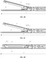
- the knife holder 1 When the knife holder 1 is in the first position, the knife holder 1 restricts the closure of the jaws 3, as shown in FIG. 3B .
- the jaws 3 are configured to be closed by external force; the first elastic member 2 is configured to drive the knife holder 1 to move from the first position to the second position.
- the first elastic member 2 when the knife holder 1 is in the first position, the first elastic member 2 is in a compressed state; when the knife holder 1 is in the second position, the first elastic member 2 is in a natural state. Therefore, the first elastic member 2 can drive the knife holder 1 to move from the first position to the second position. Meanwhile, since the first elastic member 2 is in the natural state when the knife holder 1 is in the second position, the first elastic member 2 at this time does not restrict the knife holder 1 from moving back from the second position to the first position.
- the knife holder 1 includes a main knife holder 110 and at least one limiting protrusion 120 disposed adjacent to the distal end of the main knife holder 110 and extending vertically outward from the main knife holder body 110 in a direction away from the main knife holder body 110.
- the abutment surface 121 of the limiting protrusion 120 of the knife holder 1 abuts against the contact part 330 of the staple cartridge assembly 33 to stop the staple cartridge assembly 33, making the jaws 3 unable to continue to close, as shown in FIG. 3B .
- the limiting protrusion 120 of the knife holder 1 disengages from the staple cartridge assembly 33.
- the limiting protrusion 120 can no longer limit the rotation of the staple cartridge assembly 33 so that the jaws 3 can be closed, specifically as shown in FIG. 3C , where the abutment surface 121 is the top surface of the limiting protrusion 120.
- the jaws 3 include an anvil 32 and a staple cartridge assembly 33, and the proximal end of the anvil 32 is rotatably connected to the proximal end of the staple cartridge assembly 33.
- the jaws 3 When the jaws 3 are open, the distal end of the anvil 32 and the distal end of the staple cartridge assembly 33 are far away from each other; when the jaws 3 are closed, the distal end of the anvil 32 and the distal end of the staple cartridge assembly 33 are close to each other.
- the staple cartridge assembly 33 begins to rotate relative to the anvil 32, the contact part 330 presses against the limiting protrusion 120 of the knife holder 1 in the first position to limit the relative rotation of the staple cartridge assembly 33 and the anvil 32.
- the limiting protrusion 120 of the knife holder 1 can no longer abut against the contact part 330 of the staple cartridge assembly 33. Therefore, at this time, the staple cartridge assembly 33 can rotate relative to the anvil 32, and the jaws 3 can be closed.
- the principle of the knife holder limiting the jaws may refer to the Chinese Patent Application Number CN202011004778.1 .
- the first direction A is marked in FIG. 1 and FIGS. 3B to FIG. 3D , and the first direction A is from the proximal end to the distal end.
- the staple cartridge assembly 33 and the anvil 32 are used to clamp the tissue
- a staple cartridge is provided in the staple cartridge assembly 33
- staples may be provided in the staple cartridge.
- the knife holder 1 moves between the first position and the second position, the cutting knife on the knife holder 1 does not cut the tissue inside the jaws 3 or cannot completely sever the tissue inside the jaws 3.
- the knife holder 1 needs to continue moving distally to completely sever the tissue inside the jaws 3. More specifically, the knife holder 1 has a cutting edge, and the knife holder is movable back and forth among the first position, the second position, and a third position; the first position, the second position, and the third position are arranged sequentially from near to far, and when the knife holder 1 moves from the second position to the third position, the cutting edge on the knife holder 1 cuts the tissue located inside the jaws 3.
- the housing assembly 4 of the surgical stapler includes an outer sleeve 41 and an inner sleeve, the outer sleeve 41 is sleeved over the inner sleeve, the proximal end of the outer sleeve 41 and the proximal end of the inner sleeve are separately connected to the distal end of the surgical stapler's handle, and the distal end of the outer sleeve 41 and the distal end of the inner sleeve are separately connected to the jaws 3. More specifically, as shown in FIGS.
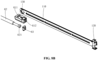
- the surgical stapler includes a first connection block 61 and a central rod 62; the proximal end of the central rod 62 is connected to the rack 52, the distal end of the central rod 62 is connected to the proximal end of the first connection block 61, and the distal end of the first connection block 61 is connected to the knife holder 1 through a second connection block 63; the proximal end of the first elastic member 2 abuts against the inner sleeve, and the distal end of the first elastic member 2 abuts against the first connection block 61.
- the first connection block 61 cooperates with the inner sleeve to compress the first elastic member 2.
- the first elastic member 2 applies force to the first connection block 61, the central rod 62, and the knife holder 1 to drive the knife holder 1 to move to the second position.
- the distance that the first elastic member 2 drives the knife holder to move may be 1.3 mm or may range from 1 mm to 3 mm.
- the proximal end of the central rod 62 is disposed in the handle 7 and is connected to the rack 52, and the distal end of the central rod 62 is disposed in the inner sleeve and is connected to the knife holder 1.
- a limiting part 621 of the central rod 62 is embedded in the first mounting slot 611 of the first connection block 61, and a knife rod mounting slot 130 of the knife holder 1 is embedded in a second mounting slot 612 of the first connection block 61 through the second connection block 63 so that when the central rod 62 moves, the first connection block 61 and the knife holder 1 are also driven to move.
- the limiting part 621 of the central rod 62 may be inserted into the first mounting slot 611 from bottom to top; the second connection block 63 is first placed in the knife rod mounting slot 130 and then embedded into the second mounting slot 612 together with the proximal end of the knife holder 1, thereby connecting the central rod 62 to the knife holder 1.
- connection between the central rod 62 and the first connection block 61 may be either a fixed connection or a detachable connection and is not limited to the preceding connection methods.
- connection between the first connection block 61 and the knife holder 1 may be either a fixed connection or a detachable connection and is not limited to the preceding connection methods.
- the inner sleeve is mainly divided into a first part 421 and a second part 422.
- the structures of the outer sleeve 41 and the inner sleeve may vary and are not limited to the structures described above.
- the outer sleeve 41 and the inner sleeve are an integral structure and cannot be separated.
- the surgical stapler includes a clutch mechanism (not shown in the figures) that drives the first gear 54 from the engaged position to the disengaged position by force, causing the first gear 54 to disengage from the rack 52.
- a clutch mechanism (not shown in the figures) that drives the first gear 54 from the engaged position to the disengaged position by force, causing the first gear 54 to disengage from the rack 52.
- the surgical stapler includes a driving device 51, a rack 52, and a first gear 54; the first gear 54 is connected to the driving device 51, the rack 52 is connected to the knife holder 1, and the first gear 54 is movable between an engaged position and a disengaged position; when the first gear 54 is in the engaged position, the first gear 54 engages with the rack 52, as shown in FIG. 6 , and the driving device 51 can then drive the central rod 62 and the first connection block 61 to move axially through the first gear 54 and the rack 52, thus further driving the movement of the knife holder 1.
- the first gear 54 is in the disengaged position, as shown in FIG.
- the first gear 54 disengages from the rack 52, allowing the first elastic member 2 to drive the knife holder 1 from the first position to the second position. It should be additionally noted that when the first gear 54 is in the engaged position, due to the engagement between the first gear 54 and the rack 52, both the rack 52 and the knife holder 1 connected to the rack 52 are locked by the driving device 51 connected to the first gear 54. At this time, the knife holder 1 in the first position does not move to the second position.
- the driving device 51 since the driving device 51 performs transmission through the first gear 54 and the rack 52, the rack 52 and the knife holder 1 fixedly connected to the rack 52 cannot move when the driving device 51 is stopped and the first gear 54 and rack 52 are in the engaged position. Once the first gear 54 disengages from the rack 52, the driving device 51 no longer affects the rack 52 and cannot lock the movement of the rack 52. Thus, the locking of the rack 52 and knife holder 1 by the driving device 51 can be effectively released.
- the output end of the driving device 51 is provided with a second gear 55, the second gear 55 is engaged with the first gear 54, and the first gear 54 can engage with the rack 52. Therefore, when the output end of the driving device 51 rotates, the second gear 55 and the first gear 54 are driven to rotate, causing the rack 52, the central rod 62, the first connection block 61, and the knife holder 1 to move.
- the driving device 51 fails, the output end of the driving device 51 is locked and unable to rotate, and the first gear 54 and the second gear 55 are also unable to rotate. Moreover, the movement of the rack 52, the central rod 62, the first connection block 61, and the knife holder 1 are locked.
- this solution is also provided with a clutch mechanism, through which the first gear 54 is pressed downwardly so that the first gear 54 disengages from the rack 52.
- the driving device 51 can no longer restrict the movement of the rack 52, the central rod 62, the first connection block 61, and the knife holder 1.
- the compressed first elastic member 2 drives the knife holder 1 to move from the first position to the second position.
- the surgical stapler includes a second elastic member 56 configured to drive the first gear to move to a position engaged with the rack 52.
- the second elastic member 56 is also compressed under force.
- the second elastic member 56 provides an upward force to the first gear 54 to return the first gear 54 to the position engaged with the rack 52. At this time, the first gear 54, the second gear 55, and the rack 52 resume transmission connection.
- a guide shaft is formed inside the handle 7 to guide the movement of the first gear 54.
- the guide shaft extends in the up-down direction, and the first gear 54 is sleeved outside the guide shaft to guide the first gear 54 to move only in the up-down direction.
- the driving device 51 is a motor.
- the first elastic member 2 and the second elastic member 56 are springs.
- the surgical stapler in the preceding embodiment when a user drives the first gear 54 to move from the engaged position to the disengaged position, the locking of the rack 52 and knife holder 1 by the driving device 51 can be released. At this time, if the knife holder 1 is in the first position, the first elastic member 2 in the compressed state drives the knife holder 1 to move from the first position to the second position so that the limiting protrusion 120 on the knife holder 1 no longer restricts the closing of the jaws 3.
- the benefit of this solution is that the user only needs to move the first gear 54 to the disengaged position, and subsequently, the surgical stapler automatically moves the knife holder 1, without the need for manual operation by the user to drive the knife holder 1 to the second position. This solution greatly improves the convenience of the surgical stapler.
- the surgical stapler in the present disclosure is particularly suitable for electric laparoscopic surgical staplers. Moreover, the surgical stapler has a simple structure and more convenient operation.
Landscapes
- Health & Medical Sciences (AREA)
- Life Sciences & Earth Sciences (AREA)
- Surgery (AREA)
- Heart & Thoracic Surgery (AREA)
- Engineering & Computer Science (AREA)
- Biomedical Technology (AREA)
- Nuclear Medicine, Radiotherapy & Molecular Imaging (AREA)
- Medical Informatics (AREA)
- Molecular Biology (AREA)
- Animal Behavior & Ethology (AREA)
- General Health & Medical Sciences (AREA)
- Public Health (AREA)
- Veterinary Medicine (AREA)
- Surgical Instruments (AREA)
Applications Claiming Priority (1)
| Application Number | Priority Date | Filing Date | Title |
|---|---|---|---|
| CN202311147289.5A CN116869590B (zh) | 2023-09-07 | 2023-09-07 | 一种吻合器 |
Publications (2)
| Publication Number | Publication Date |
|---|---|
| EP4520274A1 true EP4520274A1 (de) | 2025-03-12 |
| EP4520274B1 EP4520274B1 (de) | 2026-04-29 |
Family
ID=88262546
Family Applications (1)
| Application Number | Title | Priority Date | Filing Date |
|---|---|---|---|
| EP24198816.1A Active EP4520274B1 (de) | 2023-09-07 | 2024-09-06 | Chirurgisches klammergerät |
Country Status (3)
| Country | Link |
|---|---|
| US (1) | US12544071B2 (de) |
| EP (1) | EP4520274B1 (de) |
| CN (1) | CN116869590B (de) |
Families Citing this family (1)
| Publication number | Priority date | Publication date | Assignee | Title |
|---|---|---|---|---|
| US20260102178A1 (en) * | 2024-10-15 | 2026-04-16 | Cilag Gmbh International | End effector knife with retention plateau |
Citations (5)
| Publication number | Priority date | Publication date | Assignee | Title |
|---|---|---|---|---|
| WO2003079909A2 (en) * | 2002-03-19 | 2003-10-02 | Tyco Healthcare Group, Lp | Surgical fastener applying apparatus |
| EP3875040A1 (de) * | 2018-11-02 | 2021-09-08 | Ezisurg (Suzhou) Medical Co., Ltd. | Sicherstellungsmechanismus zur sicherstellung, dass eine vorrichtung nur einmal verwendet werden kann |
| WO2022110250A1 (zh) * | 2020-11-30 | 2022-06-02 | 苏州英途康医疗科技有限公司 | 吻合器 |
| US20220378417A1 (en) * | 2021-05-25 | 2022-12-01 | Covidien Lp | Powered stapling device with manual retraction |
| EP4218611A1 (de) * | 2020-09-22 | 2023-08-02 | Ezisurg Medical Co., Ltd. | Endeffektor für anastomat |
Family Cites Families (29)
| Publication number | Priority date | Publication date | Assignee | Title |
|---|---|---|---|---|
| DE9418094U1 (de) * | 1994-11-15 | 1995-01-12 | Tontarra Medizintechnik GmbH, 78573 Wurmlingen | Chirurgisches Rohrschaftinstrument |
| US5653721A (en) * | 1995-10-19 | 1997-08-05 | Ethicon Endo-Surgery, Inc. | Override mechanism for an actuator on a surgical instrument |
| US6582451B1 (en) * | 1999-03-16 | 2003-06-24 | The University Of Sydney | Device for use in surgery |
| ITSS20000003A1 (it) | 2000-05-10 | 2001-11-10 | Giuseppe Pilo | Bisturi chirurgico monouso sicuro |
| US8806973B2 (en) * | 2009-12-02 | 2014-08-19 | Covidien Lp | Adapters for use between surgical handle assembly and surgical end effector |
| US7357287B2 (en) * | 2005-09-29 | 2008-04-15 | Ethicon Endo-Surgery, Inc. | Surgical stapling instrument having preloaded firing assistance mechanism |
| WO2008045394A2 (en) * | 2006-10-05 | 2008-04-17 | Tyco Healthcare Group Lp | Flexible endoscopic stitching devices |
| US20090206137A1 (en) * | 2008-02-15 | 2009-08-20 | Ethicon Endo-Surgery, Inc. | Disposable loading units for a surgical cutting and stapling instrument |
| AU2011308701B2 (en) * | 2010-09-30 | 2013-11-14 | Ethicon Endo-Surgery, Inc. | Fastener system comprising a retention matrix and an alignment matrix |
| RU2581715C2 (ru) * | 2010-10-01 | 2016-04-20 | Этикон Эндо-Серджери, Инк. | Хирургический инструмент с элементом бранши |
| US9161807B2 (en) * | 2011-05-23 | 2015-10-20 | Covidien Lp | Apparatus for performing an electrosurgical procedure |
| US8764769B1 (en) * | 2013-03-12 | 2014-07-01 | Levita Magnetics International Corp. | Grasper with magnetically-controlled positioning |
| US9289211B2 (en) * | 2013-03-13 | 2016-03-22 | Covidien Lp | Surgical stapling apparatus |
| US9681870B2 (en) * | 2013-12-23 | 2017-06-20 | Ethicon Llc | Articulatable surgical instruments with separate and distinct closing and firing systems |
| US9839428B2 (en) * | 2013-12-23 | 2017-12-12 | Ethicon Llc | Surgical cutting and stapling instruments with independent jaw control features |
| US9801679B2 (en) * | 2014-01-28 | 2017-10-31 | Ethicon Llc | Methods and devices for controlling motorized surgical devices |
| CN203776973U (zh) * | 2014-04-04 | 2014-08-20 | 苏州天臣国际医疗科技有限公司 | 钉仓组件及具有该钉仓组件的吻合器 |
| US9795380B2 (en) * | 2014-09-02 | 2017-10-24 | Ethicon Llc | Devices and methods for facilitating closing and clamping of an end effector of a surgical device |
| CN106913362B (zh) * | 2015-12-28 | 2019-06-14 | 天津瑞奇外科器械股份有限公司 | 末端执行器及其钉匣部分、外科手术器械 |
| DK3464285T3 (da) | 2016-06-01 | 2022-12-19 | Biosplice Therapeutics Inc | Fremgangsmåde til fremstilling af n-(5-(3-(7-(3-fluorphenyl)-3h-imidazo[4,5-c]pyridin-2-yl)-1h-indazol-5-yl)pyridin-3-yl)-3-methylbutanamid |
| CN105919641B (zh) * | 2016-06-08 | 2019-07-12 | 宁波维尔凯迪医疗器械有限公司 | 一种电动腔镜吻合器 |
| US10537324B2 (en) * | 2016-12-21 | 2020-01-21 | Ethicon Llc | Stepped staple cartridge with asymmetrical staples |
| US10765442B2 (en) * | 2017-04-14 | 2020-09-08 | Ethicon Llc | Surgical devices and methods for biasing an end effector to a closed configuration |
| AU2019232836A1 (en) * | 2018-10-12 | 2020-04-30 | Covidien Lp | Apparatus for endoscopic procedures |
| CN111466981B (zh) * | 2019-01-24 | 2021-05-28 | 苏州英途康医疗科技有限公司 | 钉仓组件及外科手术器械 |
| US11464510B2 (en) * | 2019-07-26 | 2022-10-11 | Covidien Lp | Reload assembly with knife carrier lockout |
| US11382704B2 (en) * | 2019-08-28 | 2022-07-12 | Cilag Gmbh International | Closure mechanism for surgical tool |
| US11701119B2 (en) * | 2021-05-26 | 2023-07-18 | Covidien Lp | Powered stapling device with rack release |
| US11576671B1 (en) * | 2021-08-20 | 2023-02-14 | Covidien Lp | Small diameter linear surgical stapling apparatus |
-
2023
- 2023-09-07 CN CN202311147289.5A patent/CN116869590B/zh active Active
-
2024
- 2024-09-06 EP EP24198816.1A patent/EP4520274B1/de active Active
- 2024-09-06 US US18/827,491 patent/US12544071B2/en active Active
Patent Citations (5)
| Publication number | Priority date | Publication date | Assignee | Title |
|---|---|---|---|---|
| WO2003079909A2 (en) * | 2002-03-19 | 2003-10-02 | Tyco Healthcare Group, Lp | Surgical fastener applying apparatus |
| EP3875040A1 (de) * | 2018-11-02 | 2021-09-08 | Ezisurg (Suzhou) Medical Co., Ltd. | Sicherstellungsmechanismus zur sicherstellung, dass eine vorrichtung nur einmal verwendet werden kann |
| EP4218611A1 (de) * | 2020-09-22 | 2023-08-02 | Ezisurg Medical Co., Ltd. | Endeffektor für anastomat |
| WO2022110250A1 (zh) * | 2020-11-30 | 2022-06-02 | 苏州英途康医疗科技有限公司 | 吻合器 |
| US20220378417A1 (en) * | 2021-05-25 | 2022-12-01 | Covidien Lp | Powered stapling device with manual retraction |
Also Published As
| Publication number | Publication date |
|---|---|
| US12544071B2 (en) | 2026-02-10 |
| CN116869590A (zh) | 2023-10-13 |
| EP4520274B1 (de) | 2026-04-29 |
| US20250082326A1 (en) | 2025-03-13 |
| CN116869590B (zh) | 2023-12-29 |
Similar Documents
| Publication | Publication Date | Title |
|---|---|---|
| US12605155B2 (en) | Jaw opening feature for surgical stapler | |
| US20250352207A1 (en) | Clamping assembly for linear surgical stapler | |
| JP6219380B2 (ja) | 発射駆動部を備えた関節屈曲式手術器具 | |
| US9192381B2 (en) | Surgical stapling apparatus with powered articulation | |
| AU2018382026B2 (en) | Staple cartridge assembly and medical stapler using the staple cartridge assembly | |
| CN105682576B (zh) | 用于电动外科缝合器械的控制特征 | |
| CN109199488B (zh) | 外科器械 | |
| CN217488731U (zh) | 手动吻合器 | |
| EP2772202A2 (de) | Integrierte Gewebepositionierung und Backenausrichtungsfunktionen für chirurgisches Klammergerät | |
| EP2772192A1 (de) | Chirurgisches Instrument mit einem Schloss mit rastender binärer Feder | |
| WO2021120448A1 (zh) | 外科器械 | |
| CN110801256B (zh) | 一种双动力腔内切割吻合器 | |
| CA2902483A1 (en) | Lockout feature for movable cutting member of surgical instrument | |
| CN109199487B (zh) | 外科器械 | |
| JP7441842B2 (ja) | 触発機構及びステープラー | |
| CN115707431B (zh) | 外科器械 | |
| CN117100342B (zh) | 外科器械 | |
| US12544071B2 (en) | Surgical stapler | |
| CN112472175B (zh) | 外科器械 | |
| CN117100343A (zh) | 外科器械 | |
| CN219147689U (zh) | 一种外科器械及其装载单元 | |
| CN115607210B (zh) | 吻合器 | |
| CN214907505U (zh) | 外科缝切装置 | |
| CN109199490B (zh) | 一种电动传动机构的手动控制装置 | |
| CN109199489B (zh) | 一种传动机构的控制装置 |
Legal Events
| Date | Code | Title | Description |
|---|---|---|---|
| PUAI | Public reference made under article 153(3) epc to a published international application that has entered the european phase |
Free format text: ORIGINAL CODE: 0009012 |
|
| STAA | Information on the status of an ep patent application or granted ep patent |
Free format text: STATUS: REQUEST FOR EXAMINATION WAS MADE |
|
| 17P | Request for examination filed |
Effective date: 20240906 |
|
| AK | Designated contracting states |
Kind code of ref document: A1 Designated state(s): AL AT BE BG CH CY CZ DE DK EE ES FI FR GB GR HR HU IE IS IT LI LT LU LV MC ME MK MT NL NO PL PT RO RS SE SI SK SM TR |
|
| GRAP | Despatch of communication of intention to grant a patent |
Free format text: ORIGINAL CODE: EPIDOSNIGR1 |
|
| STAA | Information on the status of an ep patent application or granted ep patent |
Free format text: STATUS: GRANT OF PATENT IS INTENDED |
|
| RIC1 | Information provided on ipc code assigned before grant |
Ipc: A61B 17/072 20060101AFI20251111BHEP |
|
| INTG | Intention to grant announced |
Effective date: 20251125 |
|
| GRAS | Grant fee paid |
Free format text: ORIGINAL CODE: EPIDOSNIGR3 |
|
| GRAA | (expected) grant |
Free format text: ORIGINAL CODE: 0009210 |
|
| STAA | Information on the status of an ep patent application or granted ep patent |
Free format text: STATUS: THE PATENT HAS BEEN GRANTED |
|
| AK | Designated contracting states |
Kind code of ref document: B1 Designated state(s): AL AT BE BG CH CY CZ DE DK EE ES FI FR GB GR HR HU IE IS IT LI LT LU LV MC ME MK MT NL NO PL PT RO RS SE SI SK SM TR |
|
| REG | Reference to a national code |
Ref country code: CH Ref legal event code: F10 Free format text: ST27 STATUS EVENT CODE: U-0-0-F10-F00 (AS PROVIDED BY THE NATIONAL OFFICE) Effective date: 20260429 Ref country code: GB Ref legal event code: FG4D |