EP4517229A2 - Kühlschrank mit am boden des kühlschrankkörpers angeordnetem verdampfer - Google Patents
Kühlschrank mit am boden des kühlschrankkörpers angeordnetem verdampfer Download PDFInfo
- Publication number
- EP4517229A2 EP4517229A2 EP25151389.1A EP25151389A EP4517229A2 EP 4517229 A2 EP4517229 A2 EP 4517229A2 EP 25151389 A EP25151389 A EP 25151389A EP 4517229 A2 EP4517229 A2 EP 4517229A2
- Authority
- EP
- European Patent Office
- Prior art keywords
- evaporator
- refrigerator
- disposed
- storage space
- inclination
- Prior art date
- Legal status (The legal status is an assumption and is not a legal conclusion. Google has not performed a legal analysis and makes no representation as to the accuracy of the status listed.)
- Granted
Links
Images


Classifications
-
- F—MECHANICAL ENGINEERING; LIGHTING; HEATING; WEAPONS; BLASTING
- F25—REFRIGERATION OR COOLING; COMBINED HEATING AND REFRIGERATION SYSTEMS; HEAT PUMP SYSTEMS; MANUFACTURE OR STORAGE OF ICE; LIQUEFACTION SOLIDIFICATION OF GASES
- F25D—REFRIGERATORS; COLD ROOMS; ICE-BOXES; COOLING OR FREEZING APPARATUS NOT OTHERWISE PROVIDED FOR
- F25D11/00—Self-contained movable devices, e.g. domestic refrigerators
- F25D11/02—Self-contained movable devices, e.g. domestic refrigerators with cooling compartments at different temperatures
-
- F—MECHANICAL ENGINEERING; LIGHTING; HEATING; WEAPONS; BLASTING
- F25—REFRIGERATION OR COOLING; COMBINED HEATING AND REFRIGERATION SYSTEMS; HEAT PUMP SYSTEMS; MANUFACTURE OR STORAGE OF ICE; LIQUEFACTION SOLIDIFICATION OF GASES
- F25D—REFRIGERATORS; COLD ROOMS; ICE-BOXES; COOLING OR FREEZING APPARATUS NOT OTHERWISE PROVIDED FOR
- F25D17/00—Arrangements for circulating cooling fluids; Arrangements for circulating gas, e.g. air, within refrigerated spaces
- F25D17/04—Arrangements for circulating cooling fluids; Arrangements for circulating gas, e.g. air, within refrigerated spaces for circulating air, e.g. by convection
- F25D17/06—Arrangements for circulating cooling fluids; Arrangements for circulating gas, e.g. air, within refrigerated spaces for circulating air, e.g. by convection by forced circulation
- F25D17/062—Arrangements for circulating cooling fluids; Arrangements for circulating gas, e.g. air, within refrigerated spaces for circulating air, e.g. by convection by forced circulation in household refrigerators
-
- F—MECHANICAL ENGINEERING; LIGHTING; HEATING; WEAPONS; BLASTING
- F25—REFRIGERATION OR COOLING; COMBINED HEATING AND REFRIGERATION SYSTEMS; HEAT PUMP SYSTEMS; MANUFACTURE OR STORAGE OF ICE; LIQUEFACTION SOLIDIFICATION OF GASES
- F25B—REFRIGERATION MACHINES, PLANTS OR SYSTEMS; COMBINED HEATING AND REFRIGERATION SYSTEMS; HEAT PUMP SYSTEMS
- F25B39/00—Evaporators; Condensers
- F25B39/02—Evaporators
-
- F—MECHANICAL ENGINEERING; LIGHTING; HEATING; WEAPONS; BLASTING
- F25—REFRIGERATION OR COOLING; COMBINED HEATING AND REFRIGERATION SYSTEMS; HEAT PUMP SYSTEMS; MANUFACTURE OR STORAGE OF ICE; LIQUEFACTION SOLIDIFICATION OF GASES
- F25D—REFRIGERATORS; COLD ROOMS; ICE-BOXES; COOLING OR FREEZING APPARATUS NOT OTHERWISE PROVIDED FOR
- F25D17/00—Arrangements for circulating cooling fluids; Arrangements for circulating gas, e.g. air, within refrigerated spaces
- F25D17/04—Arrangements for circulating cooling fluids; Arrangements for circulating gas, e.g. air, within refrigerated spaces for circulating air, e.g. by convection
- F25D17/06—Arrangements for circulating cooling fluids; Arrangements for circulating gas, e.g. air, within refrigerated spaces for circulating air, e.g. by convection by forced circulation
- F25D17/062—Arrangements for circulating cooling fluids; Arrangements for circulating gas, e.g. air, within refrigerated spaces for circulating air, e.g. by convection by forced circulation in household refrigerators
- F25D17/065—Arrangements for circulating cooling fluids; Arrangements for circulating gas, e.g. air, within refrigerated spaces for circulating air, e.g. by convection by forced circulation in household refrigerators with compartments at different temperatures
-
- F—MECHANICAL ENGINEERING; LIGHTING; HEATING; WEAPONS; BLASTING
- F25—REFRIGERATION OR COOLING; COMBINED HEATING AND REFRIGERATION SYSTEMS; HEAT PUMP SYSTEMS; MANUFACTURE OR STORAGE OF ICE; LIQUEFACTION SOLIDIFICATION OF GASES
- F25D—REFRIGERATORS; COLD ROOMS; ICE-BOXES; COOLING OR FREEZING APPARATUS NOT OTHERWISE PROVIDED FOR
- F25D17/00—Arrangements for circulating cooling fluids; Arrangements for circulating gas, e.g. air, within refrigerated spaces
- F25D17/04—Arrangements for circulating cooling fluids; Arrangements for circulating gas, e.g. air, within refrigerated spaces for circulating air, e.g. by convection
- F25D17/06—Arrangements for circulating cooling fluids; Arrangements for circulating gas, e.g. air, within refrigerated spaces for circulating air, e.g. by convection by forced circulation
- F25D17/067—Evaporator fan units
-
- F—MECHANICAL ENGINEERING; LIGHTING; HEATING; WEAPONS; BLASTING
- F25—REFRIGERATION OR COOLING; COMBINED HEATING AND REFRIGERATION SYSTEMS; HEAT PUMP SYSTEMS; MANUFACTURE OR STORAGE OF ICE; LIQUEFACTION SOLIDIFICATION OF GASES
- F25D—REFRIGERATORS; COLD ROOMS; ICE-BOXES; COOLING OR FREEZING APPARATUS NOT OTHERWISE PROVIDED FOR
- F25D21/00—Defrosting; Preventing frosting; Removing condensed or defrost water
- F25D21/06—Removing frost
- F25D21/08—Removing frost by electric heating
-
- F—MECHANICAL ENGINEERING; LIGHTING; HEATING; WEAPONS; BLASTING
- F25—REFRIGERATION OR COOLING; COMBINED HEATING AND REFRIGERATION SYSTEMS; HEAT PUMP SYSTEMS; MANUFACTURE OR STORAGE OF ICE; LIQUEFACTION SOLIDIFICATION OF GASES
- F25D—REFRIGERATORS; COLD ROOMS; ICE-BOXES; COOLING OR FREEZING APPARATUS NOT OTHERWISE PROVIDED FOR
- F25D21/00—Defrosting; Preventing frosting; Removing condensed or defrost water
- F25D21/14—Collecting or removing condensed and defrost water; Drip trays
-
- F—MECHANICAL ENGINEERING; LIGHTING; HEATING; WEAPONS; BLASTING
- F25—REFRIGERATION OR COOLING; COMBINED HEATING AND REFRIGERATION SYSTEMS; HEAT PUMP SYSTEMS; MANUFACTURE OR STORAGE OF ICE; LIQUEFACTION SOLIDIFICATION OF GASES
- F25D—REFRIGERATORS; COLD ROOMS; ICE-BOXES; COOLING OR FREEZING APPARATUS NOT OTHERWISE PROVIDED FOR
- F25D23/00—General constructional features
- F25D23/006—General constructional features for mounting refrigerating machinery components
-
- F—MECHANICAL ENGINEERING; LIGHTING; HEATING; WEAPONS; BLASTING
- F25—REFRIGERATION OR COOLING; COMBINED HEATING AND REFRIGERATION SYSTEMS; HEAT PUMP SYSTEMS; MANUFACTURE OR STORAGE OF ICE; LIQUEFACTION SOLIDIFICATION OF GASES
- F25D—REFRIGERATORS; COLD ROOMS; ICE-BOXES; COOLING OR FREEZING APPARATUS NOT OTHERWISE PROVIDED FOR
- F25D2317/00—Details or arrangements for circulating cooling fluids; Details or arrangements for circulating gas, e.g. air, within refrigerated spaces, not provided for in other groups of this subclass
- F25D2317/06—Details or arrangements for circulating cooling fluids; Details or arrangements for circulating gas, e.g. air, within refrigerated spaces, not provided for in other groups of this subclass with forced air circulation
- F25D2317/065—Details or arrangements for circulating cooling fluids; Details or arrangements for circulating gas, e.g. air, within refrigerated spaces, not provided for in other groups of this subclass with forced air circulation characterised by the air return
- F25D2317/0651—Details or arrangements for circulating cooling fluids; Details or arrangements for circulating gas, e.g. air, within refrigerated spaces, not provided for in other groups of this subclass with forced air circulation characterised by the air return through the bottom
-
- F—MECHANICAL ENGINEERING; LIGHTING; HEATING; WEAPONS; BLASTING
- F25—REFRIGERATION OR COOLING; COMBINED HEATING AND REFRIGERATION SYSTEMS; HEAT PUMP SYSTEMS; MANUFACTURE OR STORAGE OF ICE; LIQUEFACTION SOLIDIFICATION OF GASES
- F25D—REFRIGERATORS; COLD ROOMS; ICE-BOXES; COOLING OR FREEZING APPARATUS NOT OTHERWISE PROVIDED FOR
- F25D2317/00—Details or arrangements for circulating cooling fluids; Details or arrangements for circulating gas, e.g. air, within refrigerated spaces, not provided for in other groups of this subclass
- F25D2317/06—Details or arrangements for circulating cooling fluids; Details or arrangements for circulating gas, e.g. air, within refrigerated spaces, not provided for in other groups of this subclass with forced air circulation
- F25D2317/066—Details or arrangements for circulating cooling fluids; Details or arrangements for circulating gas, e.g. air, within refrigerated spaces, not provided for in other groups of this subclass with forced air circulation characterised by the air supply
- F25D2317/0665—Details or arrangements for circulating cooling fluids; Details or arrangements for circulating gas, e.g. air, within refrigerated spaces, not provided for in other groups of this subclass with forced air circulation characterised by the air supply from the top
-
- F—MECHANICAL ENGINEERING; LIGHTING; HEATING; WEAPONS; BLASTING
- F25—REFRIGERATION OR COOLING; COMBINED HEATING AND REFRIGERATION SYSTEMS; HEAT PUMP SYSTEMS; MANUFACTURE OR STORAGE OF ICE; LIQUEFACTION SOLIDIFICATION OF GASES
- F25D—REFRIGERATORS; COLD ROOMS; ICE-BOXES; COOLING OR FREEZING APPARATUS NOT OTHERWISE PROVIDED FOR
- F25D2317/00—Details or arrangements for circulating cooling fluids; Details or arrangements for circulating gas, e.g. air, within refrigerated spaces, not provided for in other groups of this subclass
- F25D2317/06—Details or arrangements for circulating cooling fluids; Details or arrangements for circulating gas, e.g. air, within refrigerated spaces, not provided for in other groups of this subclass with forced air circulation
- F25D2317/068—Details or arrangements for circulating cooling fluids; Details or arrangements for circulating gas, e.g. air, within refrigerated spaces, not provided for in other groups of this subclass with forced air circulation characterised by the fans
- F25D2317/0683—Details or arrangements for circulating cooling fluids; Details or arrangements for circulating gas, e.g. air, within refrigerated spaces, not provided for in other groups of this subclass with forced air circulation characterised by the fans the fans not of the axial type
Definitions
- the present invention relates to the technical field of household appliances, and particularly relates to a refrigerator having an evaporator disposed at the bottom of a refrigerator body.
- Refrigerators need to provide an available volume as large as possible while occupying less space.
- an evaporator is disposed at a back portion of the refrigerator and occupies a large depth space, so it cannot meet the requirements of an ultra-thin refrigerator body.
- a refrigerator having an evaporator at the bottom appears in the prior art.
- the evaporator is horizontally placed, which has various defects. Since the evaporator is transversely disposed at the bottom of the refrigerator, most of the bottom space of the refrigerator is occupied, the space utilization of the refrigerator is reduced. A horizontal arrangement method causes vortex to exist around the evaporator, leading to poor circulative performance of an air path. Defrosting water of the evaporator may also be easily accumulated on the surface of the evaporator, causing evaporator frosting or even freezing.
- An objective of the present invention is to provide a refrigerator having an evaporator disposed at the bottom of a refrigerator body capable of at least solving any one of the above problems.
- a further objective of the present invention is to improve the space utilization of the refrigerator.
- Another further objective of the present invention is to improve an air path.
- the present invention provides a refrigerator having an evaporator disposed at the bottom of a refrigerator body, including: the refrigerator body having a bottom inner liner, the bottom inner liner defining a cooling compartment and a storage space, and the cooling compartment being disposed below the storage space; and the evaporator arranged in the cooling component and placed inclinedly along the depth direction of the refrigerator with respect to the horizontal direction, with the direction of inclination being upward from front to back.
- the evaporator is generally in the shape of a flat cuboid, and a proportion of a distance between a front side surface and a rear side surface of the evaporator to a distance between a top surface and a bottom surface of the evaporator ranges from 1.9 to 2.1.
- the distance between the front side surface and the rear side surface of the evaporator ranges from 150 mm to 155 mm; and the distance between the top surface and the bottom surface of the evaporator ranges from 73 mm to 78 mm.
- a bottom wall of the bottom inner liner includes: a first inclination portion disposed inclinedly downward from a front end of the bottom wall of the bottom inner liner from front to back; a recessed portion disposed at a rear side of the first inclination portion and configured to be inclined upward from a transverse middle to two sides to form a drain hole in the transverse middle, the drain hole being configured to drain water from the cooling compartment; and a second inclination portion disposed inclinedly upward from a rear end of the lower recessed portion from front to back and configured to support the evaporator, a front end of the evaporator abutting against the first inclination portion so that water on the evaporator is gathered at the recessed portion, and a position of the drain hole along the front and rear direction of the refrigerator body is at a front portion of the evaporator.
- the bottom wall of the bottom inner liner further includes: a third inclination portion disposed inclinedly upward from a rear end of the second inclination portion from front to back and having an inclination angle greater than that of the second inclination portion.
- the refrigerator further includes: a refrigeration fan disposed on the third inclination portion and configured to promote formation of a refrigeration airflow sent to the storage space via the evaporator; and an air supply duct disposed at a downstream of an air supply direction of the refrigeration fan and configured to convey the refrigeration airflow to the storage space.
- the refrigeration fan is a centrifugal fan
- the centrifugal fan includes a volute and an impeller disposed in the volute, the volute is fixed to the third inclination portion, and a suction inlet of the volute faces a front upper side to suck air undergone heat exchange through the evaporator by utilizing the impeller; and an exhaust outlet of the volute is located at a rear side, and the air supply duct is connected with the exhaust outlet, extends upward and is configured to upward guide the refrigeration airflow to the storage space.
- the refrigerator body further includes: an evaporator upper cover transversely disposed in the bottom inner liner and used to separate the cooling compartment from the storage space.
- the evaporator upper cover includes: a first upper cover portion located at the top of the evaporator and basically horizontally disposed; and a second upper cover portion extending inclinedly upward from a rear end of the first upper cover portion and disposed in a manner of being parallel to the centrifugal fan and forming a set distance from the centrifugal fan. Air sucked by the centrifugal fan enters the suction inlet through a gap between the centrifugal fan and the second upper cover portion.
- a space between the centrifugal fan and the second upper cover portion is smaller than or equal to 30 mm.
- an inclination angle of the third inclination portion with respect to the horizontal direction ranges from 36.0° to 37.0°.
- the evaporator of the refrigerator of the present invention is inclinedly disposed along the depth direction of the refrigerator with respect to the horizontal direction, which breaks through the technical constraint that an evaporator needs to be horizontally placed to reduce a depth size in the prior art, and improves the space utilization.
- a length in the front and rear direction may be increased due to inclined placement of the evaporator in the shape of a flat cuboid, the arrangement of other components in the cooling compartment is more reasonable through the inclined placement of the evaporator.
- practical airflow flow field analysis it is proved that the air path is improved, the airflow can flow more smoothly and uniformly throughout an air return process, and the air circulation efficiency is higher.
- the evaporator is in inclined arrangement, so that defrosting water of the evaporator can more easily flow to the drain hole, and the water drainage is smoother.
- orientations or position relationships indicated by the terms “longitudinal”, “transverse”, “length”, “width”, “thickness”, “upper”, “lower”, “front”, “rear”, “left”, “right”, “vertical”, “horizontal”, “top”, “bottom”, “depth”, etc. are based on the orientation of the refrigerator in the normal use state as a reference, and may be determined with reference to the orientations or position relationships shown in the drawings, for example, "front” indicating the orientation refers to a side of the refrigerator facing a user.
- Figure 1 is a schematic front view of a refrigerator body 100 in a refrigerator according to an embodiment of the present invention.
- Figure 2 is a schematic stereogram of the refrigerator body 100 shown in Figure 1.
- Figure 1 and Figure 2 mainly show a structure of a bottom of the refrigerator body 100.
- the refrigerator generally may include the refrigerator body 100.
- the refrigerator body 100 may include a casing, an inner liner, a heat insulation layer and other accessories.
- the casing is an outer layer structure of the refrigerator, and protects the whole refrigerator.
- the heat insulation layer is added between the casing and the inner liner of the refrigerator body 100, and the heat insulation layer is generally formed through a foaming process.
- the inner liner may be divided into a refrigerating inner liner, a variable-temperature inner liner, a freezing inner liner, etc.
- a plurality of inner liners may be vertically arranged and disposed.
- a bottom inner liner 101 defines a cooling compartment 110 and a storage space 120, and the cooling compartment 110 is disposed below the storage space 120.
- the storage space 120 may be a space for storage at the very bottom of the refrigerator.
- the bottom inner liner 101 is a freezing inner liner, and the storage space 120 forms a freezing compartment.
- a variable-temperature compartment defined in the variable-temperature inner liner, a refrigerating compartment defined in the refrigerating inner liner, etc. may be disposed above the freezing compartment according to requirements.
- the quantities and functions of specific storage compartments may be set according to the requirements of the refrigerator.
- a door body is also disposed at the front side of the refrigerator body 100, to open or close the storage compartments. In order to show an inside structure of the refrigerator body 100, the door body is not shown in the figures.
- a ratio of a volume of the storage space 120 to an integral volume of the refrigerator body 100 is set to be greater than or equal to 17.9%, for example, is set to be 17.9% to improve the space utilization efficiency of the storage space 120.
- the volume of the refrigerator body 100 may be set to be 992.2 dm3, the volume of the storage space 120 is 178 L, and the ratio of the volume of the storage space 120 to the integral volume of the refrigerator body 100 is 17.9%.
- the ratio of the volume of the storage space 120 to the integral volume of the refrigerator body 100 is set through structure optimization made according to space requirements and refrigeration performance requirements, and the effect is verified through trail products. Under the condition of reducing the size of the refrigerator body, the volume of the storage space 120 can be enabled not to change, and the volume requirements of the freezing compartment are met.
- An evaporator upper cover 130 and a longitudinal separation plate 140 may be disposed in the bottom inner liner 101.
- the evaporator upper cover 130 is transversely disposed in the bottom inner liner 101 and configured to separate the cooling compartment from the storage space 120.
- the evaporator upper cover 130 is used as a bottom wall of the storage space 120 and the top of the cooling compartment at the same time, and the storage space 120 above the evaporator upper cover is used for article storage.
- a compressor compartment 150 is formed under the cooling compartment 110, and is configured to install a compressor and a condenser of the refrigerator.
- a front portion of a compressor compartment top cover 151 is parallel to a third inclination portion 1013, and the flowability of a foaming layer is improved. Additionally, the compressor compartment top cover 151 is disposed with an interval from the bottom wall of the bottom inner liner 101.
- the parallel space from the front portion of the compressor compartment top cover 151 to the third inclination portion 1013 may be set to be smaller than or equal to 45 mm, for example, may be set to be 45 mm.
- the parallel space from the front portion of the compressor compartment top cover 151 to the third inclination portion 1013 is set through structure optimization made according to space performance requirements, and the effect is verified through trail products.
- a foaming layer is disposed at the outer side of the bottom inner liner 101.
- a thickness of the foaming layer at two sides of the bottom inner liner 101 is set to be smaller than or equal to 65 mm.
- An integral width of the refrigerator body 100 is 905 mm. After the thickness of the foaming layer is reduced, the volume of the storage space 120 may be increased. There is a conflict between the thickness of the foaming layer and the heat insulation performance. The reduction of the thickness of the foaming layer to 65 mm is set through structure optimization made according to space requirements and heat insulation performance requirements, and the effect is verified through trail products.
- a foaming layer may also be disposed between the compressor compartment top cover 151 and the bottom inner liner 101, to prevent heat of the compressor compartment 150 from affecting the freezing of the storage space 120. Due to the limitation of the space between the compressor compartment top cover 151 and the third inclination portion 1013, the thickness of the foaming layer at two sides of the bottom inner liner 101 is smaller than or equal to 45 mm. This is set through structure optimization made according to space requirements and heat insulation performance requirements, and the effect is verified through trail products.
- the longitudinal separation plate 140 is disposed in the middle of the storage space 120, and separates the storage space 120 into two transversely arranged storage cavities. That is, the storage space 120 is provided with a left storage cavity and a right storage cavity, and each of the two storage cavities may be respectively provided with a door body to form a double-door structure.
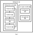
- FIG. 3 is a schematic block diagram of a refrigerator according to an embodiment of the present invention.
- a refrigeration system 300 may be a refrigeration circulation system composed of a compressor 310, a condenser 320, a throttling device 330, an evaporator 340, etc.
- the evaporator 340 is configured to provide cold directly or indirectly into the storage space 120.
- the refrigerator realizes circulation of a refrigeration airflow between the evaporator 340 and the storage compartment through an air duct system. Since a circulation structure and a working principle of the refrigeration system are well known and can be easily realized by those skilled in the art, the refrigeration system is not illustrated in detail below in order not to obscure the inventive aspects of the present application.
- An air supply assembly 400 is configured to form airflow circulation between the cooling compartment and the storage space 120, and may specifically include a refrigeration fan 410 and an air supply duct 420.
- a rated refrigeration power or a maximum refrigeration power of the refrigeration system according to the present embodiment is set to be not lower than 150 W. That is, the refrigeration capacity of the refrigeration system is not lower than 150 W.
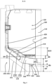
- Figure 4 is a schematic section view along a cutting plane line A-A in Figure 1 , and shows a longitudinal size of each component.
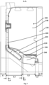
- Figure 5 is also a schematic section view along a cutting plane line A-A in Figure 1 , and shows a depth size of each component in a front and rear direction.
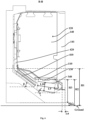
- Figure 6 is a schematic section view along a cutting plane line B-B in Figure 1 .
- Figure 7 is a schematic diagram of a longitudinal section at a lower portion of a refrigerator body in a refrigerator according to an embodiment of the present invention.
- cutting plane lines are omitted in Figure 4 , Figure 5 and Figure 6 , and only component profiles are remained.
- the cooling compartment 110 is disposed below the storage space 120, and is configured to install the evaporator 340 and a part of air supply assembly 400.
- the refrigerator according to the present embodiment has the evaporator 340 disposed in the cooling compartment 110.
- the depth size (a distance in the front and rear direction) of the refrigerator body 100 is reduced, and the depth size is possibly used for the storage space 120; and on the other hand, the bottom of the storage space 120 is heightened, so that the use inconvenience caused by the article taking and placement operation performed with the need of large bending or squatting of a user is avoided.
- the depth size of the refrigerator body 100 of the refrigerator according to the present embodiment along the front and rear direction is set to be smaller than or equal to 510 mm.
- the refrigerator according to the present embodiment realizes the arrangement of the evaporator 340 of the refrigeration system with the rated refrigeration power or maximum refrigeration power not lower than 150 W in the cooling compartment 110 under the condition that the depth size is smaller than or equal to 510 mm, and thus the normal operation and energy consumption standard requirements of the refrigerator are met.
- the evaporator 340 is generally in the shape of a flat cuboid. That is, a thickness size of the evaporator 340 vertical to a support surface is obviously smaller than a length size of the evaporator 340.
- the evaporator 340 may be a finned evaporator, and an arrangement direction of fins is parallel to the front and rear depth direction to facilitate an airflow to pass from front to back. In the present embodiment, the evaporator 340 may also be set to present other shapes according to requirements under the condition of meeting space requirements.
- the evaporator 340 in the shape of a flat cuboid is an implementation with a relatively compact and simple structure.
- the evaporator According to a refrigerator having an evaporator disposed at the bottom in the prior art, the evaporator is horizontally placed, and when an airflow enters a cooling compartment, it is easily gathered at a front end of the evaporator and cannot smoothly enter the evaporator to realize heat exchange. Additionally, an air suction space at an upper portion of a centrifugal fan is small, the airflow after the heat exchange cannot sufficiently enter the fan, and thus the air return efficiency is reduced. Airflow gathering also easily occurs under the condition that a connecting portion of an exhaust direction of the centrifugal fan and the air duct is too narrow, the airflow cannot be sufficiently blown into the air duct, and the air return and refrigeration efficiency is reduced.
- the evaporator 340 is generally in the shape of a flat cuboid, and is inclinedly disposed in the cooling compartment 110, which breaks through the technical constraint that the evaporator 340 needs to be horizontally placed to reduce a depth size in the prior art.
- An inclination angle ⁇ of the evaporator 340 with respect to the horizontal direction ranges from 7.0° to 8.0°, for example, may be set to be 7.2°, 7.5° or 7.8°, and is preferably set to be 7.5°.
- a layout of inclined placement of the evaporator 340 is one of main technical improvements of the present embodiment.
- a distance between a front side surface and a rear side surface of the evaporator 340 ranges from 150 mm to 155 mm, for example, may be set to be 152 mm, 153 mm or 154 mm, and is preferably set to be 152 mm.
- a distance between a top surface and a bottom surface of the evaporator 340 ranges from 73 mm to 78 mm, for example, may be set to be 74 mm, 75 mm or 76 mm, and may be preferably set to be 75 mm.
- a proportion of the distance between the front side surface and the rear side surface of the evaporator 340 to the distance between the top surface and the bottom surface of the evaporator 340 ranges from 1.9 to 2.1, for example, may be set to be 1.95, 2.0 or 2.05, and is preferably set to be 2.0. Due to inclined placement of the evaporator 340, a hollow groove 104 configured to collect condensed water is formed under the evaporator 340.
- the airflow may enter the evaporator 340 from the front side surface of the evaporator 340 to perform heat exchange, and a part of the airflow may also enter the evaporator 340 through two parts including the upper portion of the evaporator 340 and the bottom hollow groove 104 to perform heat exchange, so that the heat exchange is more uniform. Then, the airflow is sent to the air supply duct 420 through the refrigeration fan 410 to refrigerate the storage space 120 at the upper portion.
- the positions and sizes of each component in the cooling compartment 110 of the refrigerator of the present embodiment in the front and rear direction are strictly set.
- a proportion of a length of the horizontal direction projection of the evaporator 340 along the front and rear direction to a depth size of the refrigerator body 100 along the front and rear direction is lower than 30%, and for example, may be set to be 29.8%.
- the depth size of the refrigerator body 100 along the front and rear direction refers to a whole horizontal length from a front end to a rear end.
- the size and arrangement manner of the evaporator 340 are set through structure optimization made according to space requirements and refrigeration performance requirements, and the effect is verified through trail products.
- the bottom wall of the bottom inner liner 101 further includes a first inclination portion 1011, a second inclination portion 1012, the third inclination portion 1013 and a recessed portion 1014.
- the first inclination portion 1011 is disposed inclinedly downward from a front end of the bottom wall of the bottom inner liner 101 from front to back.
- the recessed portion 1014 is disposed at a rear side of the first inclination portion 1011 and is configured to be inclined upward from a transverse middle to two sides to form a drain hole 103 in the transverse middle.
- the drain hole 103 is configured to drain water from the cooling compartment 110.
- the position of the drain hole 103 is generally in a region of the transverse middle portion, but is not strictly required to be in a region of a transverse center. In some embodiments, the drain hole 103 may be located in a position properly near one side in the transverse middle portion.
- the second inclination portion 1012 is disposed inclinedly upward from a rear end of the recessed portion 1014 from front to back and is configured to support the evaporator 340. Additionally, a front end of the evaporator 340 abuts against the first inclination portion 1011. The evaporator 340 is disposed on the second inclination portion 1012, so that water on the evaporator 340 is gathered at the recessed portion 1014, and a position of the drain hole 103 along the front and rear direction of the refrigerator body is at a front portion of the evaporator 340.
- An inclination angle of the evaporator 340 keeps consistent with an inclination angle of the second inclination portion 1012 with respect to the horizontal plane
- the inclination angle ⁇ ranges from 7.0° to 8.0°, for example, may be set to be 7.2°, 7.5° or 7.8°, and may be preferably set to be 7.5°. That is, the recessed portion 1014 provided with the drain hole 103 is formed in a connecting position of the first inclination portion 1011 and the second inclination portion 1012, so that the drain hole 103 is used to drain condensed water of the evaporator 340.
- a height of the drain hole 103 with respect to the bottom surface of the refrigerator body 100 may be set to be smaller than or equal to 66 mm, and for example, may be set to be 66 mm.
- a height from the position of the evaporator 340 abutted against the first inclination portion 1011 to the drain hole 103 may be set to be smaller than or equal to 22 mm, and for example, may be set to be 22 mm.
- the height of the drain hole 103 is reduced to the lowest on the premise of ensuring a water drainage angle.
- the setting of the height of the drain hole 103 with respect to the bottom surface of the refrigerator body 100 and the height from the position of the evaporator 340 abutted against the first inclination portion 1011 to the drain hole 103 is performed through structure optimization made according to water drain performance requirements and space requirements, and the effect is verified through trail products.
- the third inclination portion 1013 is disposed inclinedly upward from the second inclination portion 1012 from front to back and has an inclination angle greater than that of the second inclination portion 1012.
- the inclination angle of the third inclination portion 1013 with respect to the horizontal direction ranges from 36.0° to 37.0°, for example, may be set to be 36.5°, 37.6° or 36.9°, and is preferably 36.7°.
- An inclination angle of the recessed portion 1014 is greater than or equal to 3°, and further, may be greater than or equal to 6°, for example.
- the inclination angle of the second inclination portion 1012 and the inclination angle of the third inclination portion 1013 are also respectively the inclination angle of the evaporator 340 and the inclination angle of the refrigeration fan 410.
- the inclination angle of the recessed portion 1014 can ensure that water is gathered to the drain hole 103.
- the inclination angle of two sides of the recessed portion 1014 may be greater than or equal to 3° (preferably 7°), so that the water at the two sides is gathered to the drain hole 103.
- the space from the evaporator 340 to the bottom wall of the bottom inner liner 101 may be reduced as much as possible, so that heat can be transferred to the recessed portion 1014 through a heating wire (not shown in the figures) of the evaporator 340, to enable defrosting water to effectively flow to the drain hole 103.
- the heat of the heating wire of the evaporator 340 is used for defrosting, the blockage of the drain hole 103 by an ice block is avoided, and additional addition of a heating wire at the drain hole 103 is not needed.
- parts of regions of the inclined evaporator 340 may be suspended to facilitate defrosting and water drainage. Since the evaporator 340 is inclinedly disposed, the distance between the evaporator 340 and the drain hole 103 may be reduced, which not only improves the space utilization of the refrigerator, but also ensures that the heating wire on the evaporator 340 can heat the region at the drain hole 103, so that the frosting risk at the drain hole 103 can be reduced.
- the inclination angle of the second inclination portion 1012 can also facilitate gathering of water to the drain hole 103, thus improving the water drainage smoothness.
- a proportion of a portion of the evaporator 340 attached to the second inclination portion 1012 to the bottom surface of the evaporator 340 is greater than or equal to 0.6, and for example, may be set to be 2/3, 3/4, etc., so that the drain hole 103 is located below the front portion of the evaporator 340. That is, the position of the drain hole 103 along the front and rear direction of the refrigerator body 100 is located at the front portion of the evaporator 340, for example, the drain hole 103 may be located below a 1/3 (or 1/4) position of the integral depth size of the evaporator 340.
- the refrigerator of the present embodiment by ensuring the attaching length of the bottom surface of the evaporator 340 to the second inclination portion 1012, the condition that air does not flow into the evaporator 340 but flows through a space between the bottom surface of the evaporator 340 and the drain hole 103 is avoided, a length of a flowing path of the air through the evaporator 340 is increased, and the heat exchange efficiency of the evaporator 340 is further improved.
- the air supply assembly 400 of the refrigerator of the present embodiment is disposed behind the evaporator 340.
- the air supply assembly 400 may include the refrigeration fan 410 and the air supply duct 420.
- the refrigeration fan 410 is inclinedly disposed behind the evaporator 340, a suction inlet of the refrigeration fan 410 faces a front upper side, and the refrigeration fan is configured to form a refrigeration airflow sent to the storage space 120 via the evaporator 340.
- the refrigeration fan 410 may be a centrifugal fan.
- the refrigeration fan 410 is disposed inclinedly upward behind the evaporator 340 from front to back, and includes a volute and an impeller disposed in the volute. The volute is fixed to the upper side of the third inclination portion 1013.
- a suction inlet of the volute faces the front upper side to suck air undergone heat exchange through the evaporator 340 by utilizing the impeller.
- An exhaust outlet of the volute is located at a rear side.
- the air supply duct 420 is connected with the exhaust outlet, extends upward, and is configured to upward guide the refrigeration airflow to the storage space 120.
- the suction inlet of the refrigeration fan 410 is generally located in the center of the volute, and the height of the suction inlet may be higher than the top end of the evaporator 340.
- the refrigeration fan 410 is disposed on the third inclination portion 1013, and keeps an inclination angle consistent with that of the third inclination portion 1013 with respect to the horizontal plane.
- the inclination angle ⁇ of the refrigeration fan 410 may also ranges from 36.0° to 37.0°, for example, may be set to be 36.5°, 36.7° or 36.9°, and is preferably 36.7°.
- the volute is formed by a lower case body and an upper cover body through buckling, which facilitates the disassembly and assembly of the volute.
- the exhaust outlet of the refrigeration fan 410 is located at the rear side, and is configured to supply air to an inclined rear side.
- the air supply duct 420 communicates with the exhaust outlet of the refrigeration fan 410, extends upward, and is configured to convey the refrigeration airflow to the storage space 120.
- An air supply port 421 communicating with the air supply duct 420 is formed in a rear wall of the storage space 120, to exhaust the refrigeration airflow into the storage space 120.
- a proportion of a thickness of an upward extending vertical section of the air supply duct 420 along the front and rear direction to the depth size of the refrigerator body 100 along the front and rear direction is smaller than 5.0%, and for example, may be 4.9%.
- a foaming layer of the refrigerator body 100 is disposed at the outer side of the cooling compartment 110 and the storage space 120, that is, located at the outer side of the bottom inner liner 101, and surrounds the bottom inner liner 101. Additionally, a proportion of the thickness of the foaming layer at the back portion of the storage space 120 to the depth size of the refrigerator body 100 along the front and rear direction is smaller than 11.2%, and for example, may be set to be 11%. There is a conflict between the thickness of the foaming layer and the heat insulation performance. The thickness of the foaming layer is set through structure optimization made according to space requirements and heat insulation requirements, and the effect is verified through trail products.
- the evaporator upper cover 130 is transversely disposed in the bottom inner liner 101, and is configured to separate the cooling compartment 110 from the storage space 120.
- An air return cover 131 is disposed at a front end of the evaporator upper cover 130, and is used as a front wall of the cooling compartment 110.
- a proportion of a horizontal distance from a front end of the air return cover 131 to the front end of the refrigerator body 100 to the depth size of the refrigerator body 100 along the front and rear direction is smaller than 4.9%, and for example, may be set to be 4.7%.
- the air return cover 131 is provided with a front air return inlet 132 communicating with the storage space 120 at the front side of the cooling compartment 110, so that an air return airflow of the storage space 120 enters the cooling compartment 110 through the front air return inlet 132 to perform heat exchange with the evaporator 340 and complete airflow circulation between the cooling compartment 110 and the storage space 120.
- the distance from the front end of the air return cover 131 to the front end of the refrigerator body 100 is set through structure optimization made according to space requirements and air return performance requirements, and the effect is verified through trail products.
- the evaporator upper cover 130 includes a first upper cover portion 1301, the first upper cover portion 1301 is located at a top portion of the evaporator 340 and is basically horizontally disposed, and the height of the first upper cover portion 1301 with respect to the bottom surface of the refrigerator body 100 may be set to be smaller than or equal to 200 mm, and for example, is 199 mm.
- the volume of the storage space 120 is enabled not to change under the condition of reducing the depth size of the cooling compartment 110, and the utilization rate of the storage space 120 is improved.
- the setting of the height of the first upper cover portion 1301 with respect to the bottom surface of the refrigerator body 100 is set through structure optimization made according to space requirements, and the effect is verified through trail products.
- the height of the first upper cover portion 1301 with respect to the ground is reduced to 223.5 mm, which also increases the effective utilization rate of the storage space 120.
- a gap space between the first upper cover portion 1301 and the evaporator 340 is filled with a heat insulation material.
- a space between the top of the front end of the evaporator 340 to the first upper cover portion 1301 may be set to be smaller than or equal to 36 mm, and for example, is 36 mm.
- a minimum space from the evaporator 340 to the first upper cover portion 1301 may be set to be smaller than or equal to 15 mm, and for example, is 15 mm.
- a thickest portion of the heat insulation material may be 36 mm, and a thinnest portion thereof may be 15 mm. On the premise of ensuring the heat insulation and thermal preservation performance, the thickness of the heat insulation material is compressed to the thinnest.
- the distance from the evaporator 340 to the first upper cover portion 1301 and the space from the front end of the evaporator 340 to the first upper cover portion 1301 are set through structure optimization made according to space requirements and heat insulation and thermal preservation performance requirements, and the effect is verified through trail products.
- the evaporator upper cover 130 further includes a second upper cover portion 1302 formed by extending inclinedly upward from a rear end of the first upper cover portion 1301.
- the second upper cover portion 1302 is located above the refrigeration fan 410, and an inclination angle thereof may be set to be consistent with the inclination angle of the refrigeration fan 410.
- a space between the refrigeration fan 410 and the second upper cover portion 1302 is set to be smaller than or equal to 30 mm, and for example, may be set to be 30 mm.
- the height of the second upper cover portion 1302 may be set to be smaller than or equal to 93 mm, and for example, set to be 93 mm, so that the refrigeration performance of the refrigerator is not influenced while an air suction space of the refrigeration fan 410 is ensured.
- the setting of the space between the refrigeration fan 410 and the second upper cover portion 1302 and the setting of the height of the second upper cover portion 1302 are set through structure optimization made according to space requirements and refrigeration performance requirements, and the effect is verified through trail products.
- the two front air return inlets 132 in vertical distribution are formed at the front side of the air return cover 131, the appearance is attractive, and children's fingers or foreign articles can be effectively prevented from entering a cooling space. Additionally, through two vertically distributed air return regions, return air more uniformly flows through the evaporator 340 after entering the cooling space, the problem of easy frosting at the front end surface of the evaporator 340 can be avoided to a certain degree, the heat exchange efficiency can be improved, the defrosting period can be prolonged, the energy is saved, and the efficiency is high.
- each inclination section of the air return cover 131 condensed water formed on the air return cover 131 can be guided to facilitate water drainage, the water dripping sound that can be sensed by human ears can be avoided, and the use experience of users is improved.
- the longitudinal separation plate 140 is disposed in the middle portion of the storage space 120 and separates the storage space 120 into two transversely arranged storage cavities. Each storage cavity is provided with one air return cover 131.
- a heat insulation vertical beam 141 is disposed in front of the longitudinal separation plate 140. The heat insulation vertical beam 141 is configured to cooperate with the door body of the storage cavity for avoiding the cold from being leaked from the edge of the door body.
- a proportion of the thickness of a heat insulation layer of the heat insulation vertical beam 141 along the front and rear direction to the depth size of the refrigerator body 100 along the front and rear direction is smaller than 8.4%, and a proportion of a horizontal distance from the front end of the evaporator 340 to the heat insulation vertical beam 141 to the depth size of the refrigerator body 100 in the front and rear direction is smaller than 7.7%.
- the thickness of the heat insulation layer of the heat insulation vertical beam 141 and the position of the heat insulation vertical beam with respect to the evaporator 340 are set through structure optimization made according to space requirements and heat insulation performance requirements, and the effect is verified through trail products.
- the thickness of the door body may be set to be smaller than or equal to 62 mm.
- Figure 8 is a schematic structure diagram after a door body 200 of a refrigerator 10 according to an embodiment of the present invention is closed. After the door body 200 is closed to seal the storage space 120, the integral depth size (integral thickness of the front and rear direction) of the refrigerator 10 may be smaller than or equal to 572 mm, so that the size requirement matched with a cupboard is met.
- a specific embodiment of a refrigerator with the depth size of a refrigerator body 100 being 510 mm will be illustrated in conjunction with the sizes provided in Figures 1 , 4 , 5 , 6 and 8 hereafter.
- the volume of the refrigerator body of the refrigerator 10 may be the same as that of a conventional 550 mm refrigerator body, and the space utilization efficiency is sufficiently achieved.
- the integral depth size L12 of the refrigerator body 100 is 510 mm, and a thickness L11 of a door body 200 is set to be 62 mm. Therefore, the integral thickness of the refrigerator is only 572 mm.
- a bottom-mounted refrigeration module includes an evaporator upper cover 130, an evaporator 340, a refrigeration fan 410, a compressor compartment 150 and apparatuses in a compartment body of the compressor compartment 150.
- a height H1 of the whole of the bottom-mounted refrigeration module with respect to the ground is 316.1 mm, and a height H4 of the bottom surface of the refrigerator body 100 with respect to the ground is 24.5 mm, so that the integral height of the bottom-mounted refrigeration module is only 291.6 mm.
- a depth size L9 of the evaporator 340 in the refrigerator 10 is 152 mm, a longitudinal size L10 thereof is 75 mm, a left and right transverse size (not shown) thereof is 470 mm, and a longitudinal height H7 thereof is 75 mm.
- An inclination angle ⁇ of the evaporator 340 with respect to the horizontal plane may be 7.5°.
- An inclination angle of a bottom wall portion of a bottom inner liner 101 for supporting the evaporator 340 with respect to the horizontal plane is correspondingly set to be 7.5°.
- the length L3 of the horizontal direction projection of the evaporator along the front and rear direction is 162 mm.
- the arrangement of other components in the cooling compartment 110 is more reasonable.
- the inclined arrangement of the evaporator 340 can also prevent the blockage of an air return port due to frosting caused by too short distance from the evaporator 340 to a heat insulation vertical beam 141.
- the refrigeration fan 410 is also inclinedly disposed.
- An inclination angle ⁇ of the refrigeration fan 410 with respect to the horizontal plane may be 36.7°, and an inclination angle of a bottom wall portion of the bottom inner liner 101 for supporting the refrigeration fan 410 with respect to the horizontal plane is also correspondingly set to be 36.7°.
- each component in the cooling compartment 110 and a storage space 120 is as follows: a horizontal distance L8 from a front end of an air return cover 131 to a front end of the refrigerator body 100 is 24 mm. A thickness L1 of a heat insulation layer of the heat insulation vertical beam 141 along the front and rear direction is set to be 42 mm. A distance L9 from a front side surface to a rear side surface of the evaporator 340 is 152 mm, and a distance L10 from a top surface to a bottom surface of the evaporator is 75 mm.
- a horizontal distance L4 from the front end of the refrigeration fan 410 to the evaporator 340 is 22 mm to reduce a depth distance between the evaporator 340 and the fan 410 to a maximum degree under the condition of ensuring no frosting of blades of the refrigeration fan 410.
- a thickness L6 of an upward extending vertical section of the air supply duct 420 along the front and rear direction is 25 mm, and therefore, a length L5 of a horizontal direction projection of an air supply assembly along the front and rear direction may be ensured to be 200 mm.
- a thickness L7 of the foaming layer at the back portion of the storage space 120 is 56 mm.
- a thickness L13 of the foaming layer at two sides of the storage space 120 is 65 mm.
- L8 is 4.7% of L12
- L6 is 4.9% of L12
- L1 is 8.2% of L12
- L2 is 7.5% of L12
- L3 is 29.8% of L12
- L4 is 4.3% of L12
- L5 is 39.2% of L12
- L7 is 11% of L12
- L9 is 49.3% of L10.
- a height H1 of the whole of the bottom-mounted refrigeration module with respect to the ground is 316.1 mm.
- a height H10 of the second upper cover portion 1302 of the evaporator upper cover 130 is 93 mm.
- a height H2 of the first upper cover portion 1301 with respect to the ground is 233.5 mm.
- the space H8 from the first upper cover portion 1301 to the top of the front end of the evaporator 340 is 36 mm.
- a height H3 of the first upper cover portion 1301 with respect to the bottom surface of the refrigerator body 100 is 199 mm.
- the minimum space H9 between the evaporator 340 and the evaporator upper cover 130 is 15 mm.
- a height H6 from the position of the evaporator 340 abutted against the first inclination portion 1011 to the drain hole 103 is 22 mm.
- a height H5 of the drain hole 103 with respect to the bottom surface of the refrigerator body 100 is 66 mm.
Landscapes
- Engineering & Computer Science (AREA)
- Physics & Mathematics (AREA)
- Mechanical Engineering (AREA)
- Thermal Sciences (AREA)
- General Engineering & Computer Science (AREA)
- Chemical & Material Sciences (AREA)
- Combustion & Propulsion (AREA)
- Cold Air Circulating Systems And Constructional Details In Refrigerators (AREA)
- Removal Of Water From Condensation And Defrosting (AREA)
- Devices That Are Associated With Refrigeration Equipment (AREA)
Applications Claiming Priority (3)
| Application Number | Priority Date | Filing Date | Title |
|---|---|---|---|
| CN202010833967.3A CN114076468A (zh) | 2020-08-18 | 2020-08-18 | 蒸发器设置于箱体底部的冰箱 |
| PCT/CN2021/110593 WO2022037411A1 (zh) | 2020-08-18 | 2021-08-04 | 蒸发器设置于箱体底部的冰箱 |
| EP21857506.6A EP4174412B1 (de) | 2020-08-18 | 2021-08-04 | Kühlschrank mit am boden des kühlschrankkörpers angeordnetem verdampfer |
Related Parent Applications (1)
| Application Number | Title | Priority Date | Filing Date |
|---|---|---|---|
| EP21857506.6A Division EP4174412B1 (de) | 2020-08-18 | 2021-08-04 | Kühlschrank mit am boden des kühlschrankkörpers angeordnetem verdampfer |
Publications (3)
| Publication Number | Publication Date |
|---|---|
| EP4517229A2 true EP4517229A2 (de) | 2025-03-05 |
| EP4517229A3 EP4517229A3 (de) | 2025-04-23 |
| EP4517229B1 EP4517229B1 (de) | 2025-12-17 |
Family
ID=80281433
Family Applications (2)
| Application Number | Title | Priority Date | Filing Date |
|---|---|---|---|
| EP25151389.1A Active EP4517229B1 (de) | 2020-08-18 | 2021-08-04 | Kühlschrank mit am boden des kühlschrankkörpers angeordnetem verdampfer |
| EP21857506.6A Active EP4174412B1 (de) | 2020-08-18 | 2021-08-04 | Kühlschrank mit am boden des kühlschrankkörpers angeordnetem verdampfer |
Family Applications After (1)
| Application Number | Title | Priority Date | Filing Date |
|---|---|---|---|
| EP21857506.6A Active EP4174412B1 (de) | 2020-08-18 | 2021-08-04 | Kühlschrank mit am boden des kühlschrankkörpers angeordnetem verdampfer |
Country Status (7)
| Country | Link |
|---|---|
| US (1) | US12704310B2 (de) |
| EP (2) | EP4517229B1 (de) |
| JP (1) | JP7496031B2 (de) |
| CN (1) | CN114076468A (de) |
| AU (1) | AU2021326859B2 (de) |
| ES (2) | ES3015476T3 (de) |
| WO (1) | WO2022037411A1 (de) |
Families Citing this family (3)
| Publication number | Priority date | Publication date | Assignee | Title |
|---|---|---|---|---|
| CN114076464B (zh) * | 2020-08-18 | 2023-04-18 | 青岛海尔电冰箱有限公司 | 风冷冰箱 |
| CN114812051B (zh) * | 2022-05-25 | 2023-04-25 | 珠海格力电器股份有限公司 | 冰箱及其蒸发器化霜控制方法 |
| CN115682579B (zh) * | 2022-11-04 | 2025-07-25 | 长虹美菱股份有限公司 | 一种侧部回风结构及基于其的冰箱 |
Family Cites Families (20)
| Publication number | Priority date | Publication date | Assignee | Title |
|---|---|---|---|---|
| US2767558A (en) * | 1955-03-30 | 1956-10-23 | Whirlpool Seeger Corp | Air blast refrigerated cabinet |
| US2994207A (en) * | 1959-02-25 | 1961-08-01 | Gen Motors Corp | Refrigerating apparatus with defrosting controls |
| US4513586A (en) * | 1982-12-16 | 1985-04-30 | Carrier Corporation | Combination compressor support and drain pan |
| CN100359266C (zh) | 2003-10-30 | 2008-01-02 | 乐金电子(天津)电器有限公司 | 冰箱 |
| DE102004058197A1 (de) * | 2004-12-02 | 2006-06-08 | BSH Bosch und Siemens Hausgeräte GmbH | Kältegerät |
| JP2007064598A (ja) * | 2005-09-02 | 2007-03-15 | Matsushita Electric Ind Co Ltd | 冷蔵庫 |
| KR20110021923A (ko) * | 2008-05-23 | 2011-03-04 | 악티에볼라겟 엘렉트로룩스 | 냉각 기기 |
| JP2010117038A (ja) * | 2008-11-11 | 2010-05-27 | Panasonic Corp | 冷蔵庫 |
| TWI577953B (zh) * | 2011-11-30 | 2017-04-11 | 強生控制科技公司 | 用以降低冷凍系統中噪音之系統及方法 |
| US20190142185A1 (en) * | 2017-11-10 | 2019-05-16 | Hill Phoenix, Inc. | Configuration for a heat exchanger in a temperature controlled case |
| CN110375504B (zh) * | 2018-04-13 | 2024-03-22 | 海尔智家股份有限公司 | 具有排水机构的冰箱 |
| CN209893732U (zh) * | 2018-04-13 | 2020-01-03 | 青岛海尔电冰箱有限公司 | 最下方储物间室与箱体底壁具有特定距离的冰箱 |
| CN208688080U (zh) * | 2018-04-13 | 2019-04-02 | 青岛海尔股份有限公司 | 冰箱 |
| CN208817806U (zh) | 2018-04-13 | 2019-05-03 | 青岛海尔股份有限公司 | 优化蒸发器安装结构的冰箱 |
| CN208688069U (zh) * | 2018-04-13 | 2019-04-02 | 青岛海尔股份有限公司 | 冰箱 |
| CN110285629B (zh) | 2018-04-13 | 2024-06-11 | 海尔智家股份有限公司 | 冷却室位于冷冻内胆内侧下部的冰箱 |
| CN110375474B (zh) * | 2018-04-13 | 2025-02-25 | 海尔智家股份有限公司 | 冷却室位于冷冻内胆内侧下部的冰箱 |
| CN208312835U (zh) * | 2018-04-25 | 2019-01-01 | 青岛海尔股份有限公司 | 双系统风冷冰箱 |
| CN211147012U (zh) * | 2019-08-23 | 2020-07-31 | 青岛海尔特种电冰柜有限公司 | 风冷卧式冷柜 |
| CN210832690U (zh) * | 2019-09-12 | 2020-06-23 | 青岛海尔电冰箱有限公司 | 冰箱 |
-
2020
- 2020-08-18 CN CN202010833967.3A patent/CN114076468A/zh active Pending
-
2021
- 2021-08-04 WO PCT/CN2021/110593 patent/WO2022037411A1/zh not_active Ceased
- 2021-08-04 US US18/019,886 patent/US12704310B2/en active Active
- 2021-08-04 EP EP25151389.1A patent/EP4517229B1/de active Active
- 2021-08-04 AU AU2021326859A patent/AU2021326859B2/en active Active
- 2021-08-04 EP EP21857506.6A patent/EP4174412B1/de active Active
- 2021-08-04 ES ES21857506T patent/ES3015476T3/es active Active
- 2021-08-04 ES ES25151389T patent/ES3060007T3/es active Active
- 2021-08-04 JP JP2023511899A patent/JP7496031B2/ja active Active
Also Published As
| Publication number | Publication date |
|---|---|
| EP4174412A4 (de) | 2023-11-29 |
| US20230272964A1 (en) | 2023-08-31 |
| ES3015476T3 (en) | 2025-05-05 |
| NZ796919A (en) | 2025-08-29 |
| WO2022037411A1 (zh) | 2022-02-24 |
| US12704310B2 (en) | 2026-08-11 |
| ES3060007T3 (en) | 2026-03-24 |
| EP4517229A3 (de) | 2025-04-23 |
| CN114076468A (zh) | 2022-02-22 |
| EP4174412C0 (de) | 2025-02-12 |
| EP4517229B1 (de) | 2025-12-17 |
| AU2021326859B2 (en) | 2024-05-23 |
| AU2021326859A1 (en) | 2023-03-02 |
| JP2023538062A (ja) | 2023-09-06 |
| EP4174412A1 (de) | 2023-05-03 |
| EP4174412B1 (de) | 2025-02-12 |
| JP7496031B2 (ja) | 2024-06-05 |
Similar Documents
| Publication | Publication Date | Title |
|---|---|---|
| CN209893730U (zh) | 冷冻室在冷却室前侧回风的冰箱 | |
| EP4517229B1 (de) | Kühlschrank mit am boden des kühlschrankkörpers angeordnetem verdampfer | |
| CN213040841U (zh) | 一种增大底部储物空间容积的冰箱 | |
| CN213040840U (zh) | 蒸发器底置式冰箱 | |
| CN210832691U (zh) | 冰箱 | |
| WO2022037721A1 (zh) | 一种增大底部储物空间容积的冰箱 | |
| EP3926263B1 (de) | Kühlschrank mit in zwei seitenwänden des kühlschrankkörpers geformten rücklufteinlässen | |
| CN111609620A (zh) | 具有两段式蒸发器的冰箱 | |
| WO2022037720A1 (zh) | 蒸发器底置式冰箱 | |
| CN111609643A (zh) | 一种用于防止冰箱排水管堵塞的漏斗及冰箱 | |
| CN209893737U (zh) | 变温室在冷却室侧壁回风的冰箱 | |
| CN113091364A (zh) | 商用立式冷柜 | |
| CN114076452A (zh) | 一种改进冷却室前端回风结构的冰箱 | |
| EP3929513A1 (de) | Kühlschrank mit luftgebläse vor der seite des verdampfers | |
| CN209893744U (zh) | 大容积冰箱 | |
| CN209893739U (zh) | 冷凝器与底进风口具有间隙的冰箱 | |
| CN209893735U (zh) | 排水口设置有过滤板的冰箱 | |
| CN111609628A (zh) | 排水口设置有过滤板的冰箱 | |
| CN111609626A (zh) | 变温室在冷却室侧壁回风的冰箱 | |
| CN111609623A (zh) | 具有l型冷凝器的冰箱 | |
| EP3926266B1 (de) | Kühlschrank mit einem quer neben und stromabwärts des verdampfers angeordneten gebläse | |
| CN210035945U (zh) | 蒸发器具有弯折结构的冰箱 | |
| CN210625065U (zh) | 回风口形成于箱体侧壁的冰箱 | |
| CN219037235U (zh) | 用于冷冻冷藏设备的制冷模块和冷冻冷藏设备 | |
| CN219037237U (zh) | 制冷模块的壳体、制冷模块和冰箱 |
Legal Events
| Date | Code | Title | Description |
|---|---|---|---|
| PUAI | Public reference made under article 153(3) epc to a published international application that has entered the european phase |
Free format text: ORIGINAL CODE: 0009012 |
|
| STAA | Information on the status of an ep patent application or granted ep patent |
Free format text: STATUS: THE APPLICATION HAS BEEN PUBLISHED |
|
| AC | Divisional application: reference to earlier application |
Ref document number: 4174412 Country of ref document: EP Kind code of ref document: P |
|
| AK | Designated contracting states |
Kind code of ref document: A2 Designated state(s): AL AT BE BG CH CY CZ DE DK EE ES FI FR GB GR HR HU IE IS IT LI LT LU LV MC MK MT NL NO PL PT RO RS SE SI SK SM TR |
|
| REG | Reference to a national code |
Ref country code: DE Ref legal event code: R079 Ipc: F25D0019000000 Ref country code: DE Ref legal event code: R079 Ref document number: 602021044822 Country of ref document: DE Free format text: PREVIOUS MAIN CLASS: F25D0023000000 Ipc: F25D0019000000 |
|
| PUAL | Search report despatched |
Free format text: ORIGINAL CODE: 0009013 |
|
| AK | Designated contracting states |
Kind code of ref document: A3 Designated state(s): AL AT BE BG CH CY CZ DE DK EE ES FI FR GB GR HR HU IE IS IT LI LT LU LV MC MK MT NL NO PL PT RO RS SE SI SK SM TR |
|
| RIC1 | Information provided on ipc code assigned before grant |
Ipc: F25D 23/00 20060101ALI20250320BHEP Ipc: F25D 11/02 20060101ALI20250320BHEP Ipc: F25D 19/00 20060101AFI20250320BHEP |
|
| STAA | Information on the status of an ep patent application or granted ep patent |
Free format text: STATUS: REQUEST FOR EXAMINATION WAS MADE |
|
| 17P | Request for examination filed |
Effective date: 20250515 |
|
| GRAP | Despatch of communication of intention to grant a patent |
Free format text: ORIGINAL CODE: EPIDOSNIGR1 |
|
| STAA | Information on the status of an ep patent application or granted ep patent |
Free format text: STATUS: GRANT OF PATENT IS INTENDED |
|
| RIC1 | Information provided on ipc code assigned before grant |
Ipc: F25D 23/00 20060101ALI20250630BHEP Ipc: F25D 19/00 20060101AFI20250630BHEP Ipc: F25D 11/02 20060101ALI20250630BHEP |
|
| INTG | Intention to grant announced |
Effective date: 20250715 |
|
| GRAS | Grant fee paid |
Free format text: ORIGINAL CODE: EPIDOSNIGR3 |
|
| GRAA | (expected) grant |
Free format text: ORIGINAL CODE: 0009210 |
|
| STAA | Information on the status of an ep patent application or granted ep patent |
Free format text: STATUS: THE PATENT HAS BEEN GRANTED |
|
| AC | Divisional application: reference to earlier application |
Ref document number: 4174412 Country of ref document: EP Kind code of ref document: P |
|
| AK | Designated contracting states |
Kind code of ref document: B1 Designated state(s): AL AT BE BG CH CY CZ DE DK EE ES FI FR GB GR HR HU IE IS IT LI LT LU LV MC MK MT NL NO PL PT RO RS SE SI SK SM TR |
|
| REG | Reference to a national code |
Ref country code: CH Ref legal event code: F10 Free format text: ST27 STATUS EVENT CODE: U-0-0-F10-F00 (AS PROVIDED BY THE NATIONAL OFFICE) Effective date: 20251217 Ref country code: GB Ref legal event code: FG4D |
|
| REG | Reference to a national code |
Ref country code: DE Ref legal event code: R096 Ref document number: 602021044822 Country of ref document: DE |
|
| REG | Reference to a national code |
Ref country code: ES Ref legal event code: FG2A Ref document number: 3060007 Country of ref document: ES Kind code of ref document: T3 Effective date: 20260324 |
|
| REG | Reference to a national code |
Ref country code: LT Ref legal event code: MG9D |
|
| PG25 | Lapsed in a contracting state [announced via postgrant information from national office to epo] |
Ref country code: NO Free format text: LAPSE BECAUSE OF FAILURE TO SUBMIT A TRANSLATION OF THE DESCRIPTION OR TO PAY THE FEE WITHIN THE PRESCRIBED TIME-LIMIT Effective date: 20260317 |
|
| PG25 | Lapsed in a contracting state [announced via postgrant information from national office to epo] |
Ref country code: FI Free format text: LAPSE BECAUSE OF FAILURE TO SUBMIT A TRANSLATION OF THE DESCRIPTION OR TO PAY THE FEE WITHIN THE PRESCRIBED TIME-LIMIT Effective date: 20251217 Ref country code: HR Free format text: LAPSE BECAUSE OF FAILURE TO SUBMIT A TRANSLATION OF THE DESCRIPTION OR TO PAY THE FEE WITHIN THE PRESCRIBED TIME-LIMIT Effective date: 20251217 |
|
| PG25 | Lapsed in a contracting state [announced via postgrant information from national office to epo] |
Ref country code: RS Free format text: LAPSE BECAUSE OF FAILURE TO SUBMIT A TRANSLATION OF THE DESCRIPTION OR TO PAY THE FEE WITHIN THE PRESCRIBED TIME-LIMIT Effective date: 20260317 |
|
| REG | Reference to a national code |
Ref country code: NL Ref legal event code: MP Effective date: 20251217 |
|
| PG25 | Lapsed in a contracting state [announced via postgrant information from national office to epo] |
Ref country code: LV Free format text: LAPSE BECAUSE OF FAILURE TO SUBMIT A TRANSLATION OF THE DESCRIPTION OR TO PAY THE FEE WITHIN THE PRESCRIBED TIME-LIMIT Effective date: 20251217 |
|
| PG25 | Lapsed in a contracting state [announced via postgrant information from national office to epo] |
Ref country code: BG Free format text: LAPSE BECAUSE OF FAILURE TO SUBMIT A TRANSLATION OF THE DESCRIPTION OR TO PAY THE FEE WITHIN THE PRESCRIBED TIME-LIMIT Effective date: 20251217 |
|
| REG | Reference to a national code |
Ref country code: AT Ref legal event code: MK05 Ref document number: 1868805 Country of ref document: AT Kind code of ref document: T Effective date: 20251217 |
|
| PG25 | Lapsed in a contracting state [announced via postgrant information from national office to epo] |
Ref country code: NL Free format text: LAPSE BECAUSE OF FAILURE TO SUBMIT A TRANSLATION OF THE DESCRIPTION OR TO PAY THE FEE WITHIN THE PRESCRIBED TIME-LIMIT Effective date: 20251217 |
|
| PG25 | Lapsed in a contracting state [announced via postgrant information from national office to epo] |
Ref country code: LT Free format text: LAPSE BECAUSE OF FAILURE TO SUBMIT A TRANSLATION OF THE DESCRIPTION OR TO PAY THE FEE WITHIN THE PRESCRIBED TIME-LIMIT Effective date: 20251217 |
|
| PG25 | Lapsed in a contracting state [announced via postgrant information from national office to epo] |
Ref country code: SM Free format text: LAPSE BECAUSE OF FAILURE TO SUBMIT A TRANSLATION OF THE DESCRIPTION OR TO PAY THE FEE WITHIN THE PRESCRIBED TIME-LIMIT Effective date: 20251217 |
|
| PG25 | Lapsed in a contracting state [announced via postgrant information from national office to epo] |
Ref country code: PL Free format text: LAPSE BECAUSE OF FAILURE TO SUBMIT A TRANSLATION OF THE DESCRIPTION OR TO PAY THE FEE WITHIN THE PRESCRIBED TIME-LIMIT Effective date: 20251217 |
|
| PG25 | Lapsed in a contracting state [announced via postgrant information from national office to epo] |
Ref country code: AT Free format text: LAPSE BECAUSE OF FAILURE TO SUBMIT A TRANSLATION OF THE DESCRIPTION OR TO PAY THE FEE WITHIN THE PRESCRIBED TIME-LIMIT Effective date: 20251217 |
|
| PG25 | Lapsed in a contracting state [announced via postgrant information from national office to epo] |
Ref country code: EE Free format text: LAPSE BECAUSE OF FAILURE TO SUBMIT A TRANSLATION OF THE DESCRIPTION OR TO PAY THE FEE WITHIN THE PRESCRIBED TIME-LIMIT Effective date: 20251217 |
|
| PG25 | Lapsed in a contracting state [announced via postgrant information from national office to epo] |
Ref country code: PT Free format text: LAPSE BECAUSE OF FAILURE TO SUBMIT A TRANSLATION OF THE DESCRIPTION OR TO PAY THE FEE WITHIN THE PRESCRIBED TIME-LIMIT Effective date: 20260417 Ref country code: IS Free format text: LAPSE BECAUSE OF FAILURE TO SUBMIT A TRANSLATION OF THE DESCRIPTION OR TO PAY THE FEE WITHIN THE PRESCRIBED TIME-LIMIT Effective date: 20260417 |
|
| PG25 | Lapsed in a contracting state [announced via postgrant information from national office to epo] |
Ref country code: CZ Free format text: LAPSE BECAUSE OF FAILURE TO SUBMIT A TRANSLATION OF THE DESCRIPTION OR TO PAY THE FEE WITHIN THE PRESCRIBED TIME-LIMIT Effective date: 20251217 |
|
| PG25 | Lapsed in a contracting state [announced via postgrant information from national office to epo] |
Ref country code: SK Free format text: LAPSE BECAUSE OF FAILURE TO SUBMIT A TRANSLATION OF THE DESCRIPTION OR TO PAY THE FEE WITHIN THE PRESCRIBED TIME-LIMIT Effective date: 20251217 |
|
| PG25 | Lapsed in a contracting state [announced via postgrant information from national office to epo] |
Ref country code: SE Free format text: LAPSE BECAUSE OF FAILURE TO SUBMIT A TRANSLATION OF THE DESCRIPTION OR TO PAY THE FEE WITHIN THE PRESCRIBED TIME-LIMIT Effective date: 20251217 |