EP4509686A1 - Zweiflügelige tür, zweiflügeliges fenster oder zweiflügelige fenstertür - Google Patents
Zweiflügelige tür, zweiflügeliges fenster oder zweiflügelige fenstertür Download PDFInfo
- Publication number
- EP4509686A1 EP4509686A1 EP24190265.9A EP24190265A EP4509686A1 EP 4509686 A1 EP4509686 A1 EP 4509686A1 EP 24190265 A EP24190265 A EP 24190265A EP 4509686 A1 EP4509686 A1 EP 4509686A1
- Authority
- EP
- European Patent Office
- Prior art keywords
- leaf
- door
- window
- active
- rebate
- Prior art date
- Legal status (The legal status is an assumption and is not a legal conclusion. Google has not performed a legal analysis and makes no representation as to the accuracy of the status listed.)
- Granted
Links
Images




Classifications
-
- E—FIXED CONSTRUCTIONS
- E06—DOORS, WINDOWS, SHUTTERS, OR ROLLER BLINDS IN GENERAL; LADDERS
- E06B—FIXED OR MOVABLE CLOSURES FOR OPENINGS IN BUILDINGS, VEHICLES, FENCES OR LIKE ENCLOSURES IN GENERAL, e.g. DOORS, WINDOWS, BLINDS, GATES
- E06B3/00—Window sashes, door leaves, or like elements for closing wall or like openings; Layout of fixed or moving closures, e.g. windows in wall or like openings; Features of rigidly-mounted outer frames relating to the mounting of wing frames
- E06B3/32—Arrangements of wings characterised by the manner of movement; Arrangements of movable wings in openings; Features of wings or frames relating solely to the manner of movement of the wing
- E06B3/34—Arrangements of wings characterised by the manner of movement; Arrangements of movable wings in openings; Features of wings or frames relating solely to the manner of movement of the wing with only one kind of movement
- E06B3/36—Arrangements of wings characterised by the manner of movement; Arrangements of movable wings in openings; Features of wings or frames relating solely to the manner of movement of the wing with only one kind of movement with a single vertical axis of rotation at one side of the opening, or swinging through the opening
- E06B3/362—Double winged doors or windows
-
- E—FIXED CONSTRUCTIONS
- E06—DOORS, WINDOWS, SHUTTERS, OR ROLLER BLINDS IN GENERAL; LADDERS
- E06B—FIXED OR MOVABLE CLOSURES FOR OPENINGS IN BUILDINGS, VEHICLES, FENCES OR LIKE ENCLOSURES IN GENERAL, e.g. DOORS, WINDOWS, BLINDS, GATES
- E06B5/00—Doors, windows, or like closures for special purposes; Border constructions therefor
- E06B5/10—Doors, windows, or like closures for special purposes; Border constructions therefor for protection against air-raid or other war-like action; for other protective purposes
- E06B5/16—Fireproof doors or similar closures; Adaptations of fixed constructions therefor
- E06B5/164—Sealing arrangements between the door or window and its frame, e.g. intumescent seals specially adapted therefor
-
- E—FIXED CONSTRUCTIONS
- E06—DOORS, WINDOWS, SHUTTERS, OR ROLLER BLINDS IN GENERAL; LADDERS
- E06B—FIXED OR MOVABLE CLOSURES FOR OPENINGS IN BUILDINGS, VEHICLES, FENCES OR LIKE ENCLOSURES IN GENERAL, e.g. DOORS, WINDOWS, BLINDS, GATES
- E06B5/00—Doors, windows, or like closures for special purposes; Border constructions therefor
- E06B5/10—Doors, windows, or like closures for special purposes; Border constructions therefor for protection against air-raid or other war-like action; for other protective purposes
- E06B5/16—Fireproof doors or similar closures; Adaptations of fixed constructions therefor
- E06B5/168—Shape of edges of wing and/or its frame specially adapted therefor
-
- E—FIXED CONSTRUCTIONS
- E06—DOORS, WINDOWS, SHUTTERS, OR ROLLER BLINDS IN GENERAL; LADDERS
- E06B—FIXED OR MOVABLE CLOSURES FOR OPENINGS IN BUILDINGS, VEHICLES, FENCES OR LIKE ENCLOSURES IN GENERAL, e.g. DOORS, WINDOWS, BLINDS, GATES
- E06B5/00—Doors, windows, or like closures for special purposes; Border constructions therefor
- E06B5/10—Doors, windows, or like closures for special purposes; Border constructions therefor for protection against air-raid or other war-like action; for other protective purposes
- E06B5/16—Fireproof doors or similar closures; Adaptations of fixed constructions therefor
- E06B5/162—Fireproof doors having windows or other openings, e.g. for permitting ventilation or escape
Definitions
- the present invention relates to a double-leaf door, a double-leaf window or a double-leaf French window, with a standing or inactive leaf with a narrow surface connecting the side edges of the side surfaces of the door leaf or window leaf of the inactive leaf, wherein the side edges of the side surfaces of the door leaf or window leaf of the inactive leaf are spaced apart from one another by a distance in the horizontal extension direction of the door leaf or window leaf of the inactive leaf, and a walking or aisle leaf with a narrow surface connecting the side edges of the side surfaces of the door leaf or window leaf of the inactive leaf, wherein the side edges of the side surfaces of the door leaf or window leaf of the inactive leaf are spaced apart from one another by a distance in the horizontal extension direction of the door leaf or window leaf of the inactive leaf, wherein in the closed state of the door or window the narrow surface of the inactive leaf and the narrow surface of the inactive leaf face one another.
- Doors and windows for closing an opening are known in the state of the art in numerous designs and for a wide variety of applications. Doors and windows serve as access and closure in buildings and must also fulfil other functions and properties depending on the application, especially in the case of doors and windows that close tightly in accordance with building regulations, such as those intended in particular for fire protection and/or smoke protection purposes.
- fire protection doors and/or smoke protection doors are designed, depending on their fire resistance duration, not only to prevent the spread of fire and/or smoke, but also sometimes to prevent an impermissible transfer of heat.
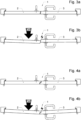
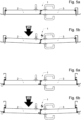
- Figures 1a and 1b, 2a and 2b , 3a and 3b, 4a and 4b , 5a and 5b , as well as 6a and 6b Examples of designs for double-leaf doors that are already known from the state of the art are shown, in which the inactive leaf and the active leaf jam in the area of the central stop when the door is opened over the inactive leaf and therefore cannot be opened. The same applies to double-leaf windows or double-leaf French doors.
- follower flaps In order to avoid jamming or forcing the passive leaf and active leaf of a double-leaf door when the door is opened via the passive leaf, the state of the art has so far provided, for example, so-called follower flaps.
- a follower flap generally causes the active leaf to be pushed in front of the passive leaf when a double-leaf door is opened via the passive leaf, i.e. in the case of a panic, in order to avoid jamming or forcing.
- the active leaf is often carried by the follower flap at least until the beginning of the effective range of a closing sequence controller.
- Such follower flaps are not very visually appealing and are often undesirable from an architectural point of view, particularly for historical and/or design reasons.
- Fig. 7a to 7f an embodiment of a double-leaf door with a carrier flap which is already known in the prior art is shown.
- the present invention is based on the object of preventing the inactive leaf and active leaf of a two-leaf door or a two-leaf window from jamming or forcing, in particular when the door is opened in a so-called panic situation, i.e. when the door is opened via the inactive leaf.
- the use of a so-called driver flap should be avoided.
- sealing problems should be avoided, in particular in the area of the so-called central stop of the two leaves, in particular with regard to fire, smoke and/or noise, so that fire protection or smoke protection purposes in particular can be met in accordance with the requirements of DIN 4102 or DIN EN 13501, DIN EN 16034 or DIN 18095 or DIN EN 1364-1+3.
- a clean seal that is sufficient for fire protection and/or smoke protection purposes should be achieved.
- a combination of a slanted rebate on the side of the inactive leaf and a round rebate on the side of the active leaf of a double-leaf door, a double-leaf window or a double-leaf French window is provided.
- the slope of the slanted rebate of the inactive leaf rests on the curve of the round rebate of the active leaf.
- the curve of the round rebate of the active leaf ensures that the slope of the slanted rebate of the inactive leaf pushes or moves the curve or the active leaf forwards, i.e. in front of the inactive leaf, and no clamping or forcing occurs.
- the curve of the round rebate slides through the slope or ramp of the slanted rebate, so that the double-leaf door or the double-leaf window can be opened further.
- the diagonal rebate of the passive leaf can be used as a so-called sliding ramp for the active leaf.
- the invention is based in particular on the finding that the narrower and thicker the leaves of the door or window are and the further the respective pivot point of the leaves is outside the door or window surface or the door or window axis of the respective leaf, the more likely the passive leaf and active leaf will jam or forcing in the area of the central stop. Furthermore, the distance or gap between the two leaves in the area of the central stop has a major influence on the jamming or forcing of the leaves. The less gap there is in the area of the center stop of the two leaves, the greater the tendency for the two leaves to jam or be forced together when the door or window is opened via the passive leaf.
- the slope of the sloped rebate of the passive leaf and the curve of the round rebate of the active leaf are coordinated in such a way that the door or window can be opened without jamming or strain. via the passive leaf.
- the inventive coordination of the slope of the sloped rebate of the passive leaf and the curvature of the round rebate of the active leaf with one another is advantageously carried out depending on or taking into account the width and thickness of the two leaves of the door or window, the position or location of the respective pivot points of the leaves, and/or the distance or gap between the two leaves in the area of the central stop thereof.
- the curvature of the round rebate of the active leaf is almost completely concealed or covered by the slope of the sloped rebate of the passive leaf when the double-leaf door or double-leaf window is closed. From the outside, the sloped rebate of the passive leaf and the round rebate of the active leaf are therefore not or almost not visible when the door or window is closed.
- a further advantageous embodiment of the invention provides that the narrow surface of the passive leaf further has or forms a step rebate, to which the diagonal rebate of the passive leaf is connected, and the narrow surface of the active leaf further has or forms a step rebate, to which the round rebate of the active leaf is connected, wherein the step rebate of the narrow surface of the passive leaf and the step rebate of the narrow surface of the active leaf are preferably designed to complement each other.
- a combination of step rebate and diagonal rebate on the part of the passive leaf and a combination of step rebate and round rebate on the part of the active leaf provided according to the invention allows a further improvement of the design with regard to fire, smoke and/or noise, in particular for fire protection purposes or smoke protection purposes in accordance with the requirements of DIN 4102 or DIN EN 13501, DIN EN 16034 or DIN 18095 or DIN EN 1364-1+3.
- a further advantageous embodiment of the invention provides that the narrow surface of the inactive leaf is at least partially provided with at least one sliding element, at least in the area of the oblique fold, and/or the narrow surface of the active leaf is at least partially provided with at least one sliding element, at least in the area of the round fold.
- the sliding element of the narrow surface of the inactive leaf and/or the sliding element of the narrow surface of the active leaf is a sliding surface made of an element with a smooth surface, preferably made of steel, non-ferrous metals (non-ferrous metals: all metals in the periodic table except iron, such as in particular copper, aluminum, zinc, nickel, lead, magnesium, gold and/or silver), ceramic, PTFE fabric, or PTFE-FRP fabric or thermosetting plastics, or a sliding roller.
- non-ferrous metals all metals in the periodic table except iron, such as in particular copper, aluminum, zinc, nickel, lead, magnesium, gold and/or silver
- ceramic such as in particular copper, aluminum, zinc, nickel, lead, magnesium, gold and/or silver
- PTFE fabric such as in particular copper, aluminum, zinc, nickel, lead, magnesium, gold and/or silver
- thermosetting plastics such as in particular thermosetting plastics
- the side surfaces of the door leaf or window sash of the inactive leaf are spaced apart from one another by a distance, preferably in a range of about 30 mm to about 120 mm, and the side surfaces of the door leaf or window sash of the active leaf are spaced apart from one another by a distance, preferably in a range of about 30 mm to about 120 mm.
- the door leaf or window sash of the inactive leaf and/or the active leaf advantageously has the following dimensions: a height h in a range of 1700 mm to 5000 mm, preferably in a range of 1900 mm to 4200 mm, a width b in a range of 400 mm to 3200 mm, preferably in a range of 400 mm to 2800 mm.
- a further advantageous embodiment of the invention is characterized by a horizontal distance of the side edges of the side surfaces of the door leaf or window sash of the passive leaf in a range from approximately 10 mm to approximately 70 mm, and/or by a horizontal distance of the side edges of the side surfaces of the door leaf or window sash of the active leaf in a range from approximately 10 mm to approximately 60 mm.
- the narrow surface of the passive leaf preferably in the area of the rebate, is or can be provided with a sealing arrangement or sealing element running in the vertical direction of extension of the door leaf or window leaf of the passive leaf
- the narrow surface of the active leaf preferably in the area of the rebate
- the sealing arrangement or the sealing element of the narrow surface of the passive leaf and the sealing arrangement or the sealing element of the narrow surface of the active leaf are preferably designed to complement each other.
- the sealing arrangement or the sealing element meets the requirements of DIN EN 1634-1+3 or DIN 18095.
- a particularly advantageous embodiment of the invention provides that the sealing arrangement or the sealing element of the narrow surface of the passive leaf and/or the sealing arrangement or the sealing element of the narrow surface of the active leaf are equipped with a heat-absorbing material and/or with a material that intumescent in the event of fire.
- the heat-absorbing material and/or the material that intumescent in the event of fire meets the requirements of DIN EN 1634-1+3.
- the door or window according to the invention is designed for the purposes of fire and/or smoke protection, and is preferably a fire protection door and/or a smoke protection door or a fire protection window and/or a smoke protection window, in particular according to DIN 4102 or DIN EN 13501, DIN EN 16034 or DIN 18095 or DIN EN 1634-1+3.
- the door leaf or window sash of the passive leaf and/or the door leaf or window sash of the active leaf has at least one fire protection pane or is made of a fire protection pane, the fire protection pane preferably consisting of a composite of at least two glass panes arranged parallel to one another, between which at least one fire protection layer is arranged, preferably made of a material that is intumescent in the event of fire.
- the fire protection pane is advantageously designed in such a way that it satisfies or meets DIN 4102 or DIN EN 13501.
- Such a fire protection pane suitable for smoke and/or fire protection purposes advantageously prevents the passage of fire and/or smoke from one fire compartment or room into another fire compartment or room.
- the fire protection layer between the parallel glass panes is activated, whereby the heat radiation is absorbed and a highly effective insulating layer is formed.
- the fire protection pane is designed according to the so-called water glass technology or according to the so-called gel technology.
- materials are used as a fire protection layer between a large number of glass panes, in particular materials containing an alkali silicate mass, which act as a foaming agent and foam up in the event of a fire.
- the layer between two The fire protection layer arranged between the glass panes, which is activated in the event of a fire is made of gel-like materials, in particular organic polymers.
- a further advantageous embodiment of the invention provides that the at least two glass panes of the fire protection pane arranged parallel to one another are spaced apart from one another by means of a profile-like spacer which forms an edge bond and which is preferably arranged between the at least two glass panes of the fire protection pane arranged parallel to one another and particularly preferably extends along the side edges of the fire protection pane.
- the edge bond of a fire protection pane according to the invention therefore has a spacer running around the edge. Such spacers are used in particular - but not exclusively - in fire protection panes using gel technology.
- the pivot point or axis of rotation for the door leaf or window sash of the passive leaf and/or the door leaf or window sash of the active leaf is usually located outside the respective door leaf level or window sash level, for which attached door or window hinges, in particular so-called construction hinges, are used, and/or within the door leaf level or window sash level, for which pivot hinges or concealed hinges are also used.
- a further advantageous embodiment of the invention is characterized by a door leaf or a window sash of the inactive leaf and/or the active leaf made of solid wood and/or wood material.
- a further embodiment of the invention is characterized by a door leaf or a window sash of the inactive leaf and/or the active leaf made of steel, aluminum and/or plastic.
- the combination of oblique rebate and round rebate according to the invention can advantageously be used on a wide variety of door constructions such as panel doors made of wood and/or wood materials, steel doors, steel frame doors or aluminum profile doors or also plastic profile doors with and/or without steel reinforcement.
- the profile geometry according to the invention of combined oblique rebate and round rebate can advantageously also be used on double-leaf window systems made of a wide variety of materials.
- a further advantageous embodiment of the invention is characterized by a combination of different door leaves or window sashes for the inactive leaf and the active leaf of the double-leaf door according to the invention or the double-leaf window, in particular a combination of solid wood, wood-based material, steel and/or glass, in particular fire-resistant glass.
- the door leaves or window leaves can advantageously be constructed as a wooden or wood-based material door leaf or window leaf with or without at least one pane, preferably a fire-resistant pane, in particular in accordance with DIN 4102 or DIN EN 13501.
- the side surfaces of the door leaves or window sashes of the passive leaf and the active leaf are or run flush with each other when the double-leaf door or the double-leaf window is closed, preferably flush with the surface.
- an improved, in particular flush, appearance is achieved, particularly when the double-leaf door or the double-leaf window is closed, and in particular no offset occurs.
- Fig. 1a shows a schematic plan view of an embodiment of a double-leaf door 1 according to the prior art in the closed state.
- the door leaves of the inactive leaf 2 and the active leaf 3 are made of solid wood and/or wood material.
- the narrow surfaces connecting the side edges of the side surfaces of the door leaf of the inactive leaf 2 and the side edges of the side surfaces of the door leaf of the active leaf 3 are provided with a single rebate, in this case a simple step rebate.
- Fig. 2a shows a schematic plan view of an embodiment of a double-leaf door 1 according to the prior art in the closed state.
- the door leaves of the inactive leaf 2 and the active leaf 3 are made of solid wood and/or wood material.
- the narrow surfaces connecting the side edges of the side surfaces of the door leaf of the inactive leaf 2 and the side edges of the side surfaces of the door leaf of the active leaf 3 are provided with a double rebate, in this case a double step rebate.
- Fig. 3a shows a schematic plan view of an embodiment of a double-leaf door 1 according to the prior art in the closed state.
- the door leaves of the inactive leaf 2 and the active leaf 3 are made of solid wood and/or wood material.
- the narrow surfaces connecting the side edges of the side surfaces of the door leaf of the inactive leaf 2 and the side edges of the side surfaces of the door leaf of the active leaf 3 are provided with a diagonal rebate.
- Fig. 4a shows a schematic plan view of an embodiment of a double-leaf door 1 according to the prior art in the closed state.
- the door leaves of the inactive leaf 2 and the active leaf 3 are made of solid wood and/or wood material.
- the narrow surfaces connecting the side edges of the side surfaces of the door leaf of the inactive leaf 2 and the side edges of the side surfaces of the door leaf of the active leaf 3 are provided with a double oblique fold.
- Fig. 5a shows a schematic plan view of an embodiment of a double-leaf door 1 according to the prior art in the closed state.
- the door leaves of the inactive leaf 2 and the active leaf 3 are made of steel.
- the narrow surfaces connecting the side edges of the side surfaces of the door leaf of the inactive leaf 2 and the side edges of the side surfaces of the door leaf of the active leaf 3 are provided with a double rebate, in this case a double step rebate.
- Fig. 6a shows a schematic plan view of an embodiment of a double-leaf door 1 according to the prior art in the closed state.
- the door leaves of the inactive leaf 2 and the active leaf 3 are made of steel.
- the narrow surfaces connecting the side edges of the side surfaces of the door leaf of the inactive leaf 2 and the side edges of the side surfaces of the door leaf of the active leaf 3 are provided with a double oblique fold.
- Fig. 7a shows a schematic plan view of an embodiment of a double-leaf door 1 with a driver flap 12 according to the prior art in the closed state.
- the door leaves of the inactive leaf 2 and the active leaf 3 are made of solid wood and/or wood-based material.
- the narrow surfaces connecting the side edges of the side surfaces of the door leaf of the inactive leaf 2 and the side edges of the side surfaces of the door leaf of the active leaf 3 are provided with a double rebate, in this case a double step rebate.
- the driver flap 12 ensures that when the door 1 is opened via the inactive leaf 2, i.e.
- Fig. 7b to 7f each show a schematic plan view of the double-leaf door 1 according to Fig. 7a with a successive opening of door 1.
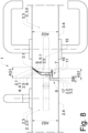
- Fig. 8 and Fig. 9a show a schematic plan view of an embodiment of a two-leaf door 1 according to the invention or a two-leaf window according to the invention, with a standing or inactive leaf 2 and a walking or active leaf 3 in the closed state.
- the inactive leaf 2 has a narrow surface 2.5 connecting the side edges 2.1 and 2.2 of the side surfaces 2.3 and 2.4 of the door leaf or window leaf 2.0 of the inactive leaf 2.
- the side edges 2.1 and 2.2 of the side surfaces 2.3 and 2.4 of the door leaf or window leaf 2.0 of the inactive leaf 2 are spaced apart from one another by a distance AS1 in the horizontal extension direction of the door leaf or window leaf 2.0 of the inactive leaf 2.
- the active leaf 3 has a narrow surface 3.5 connecting the side edges 3.1 and 3.2 of the side surfaces 3.3 and 3.4 of the door leaf or window leaf 3.0 of the active leaf 3.
- the side edges 3.1 and 3.2 of the side surfaces 3.3 and 3.4 of the door leaf or window leaf 3.0 of the active leaf 3 are spaced apart from one another by a distance AG1 in the horizontal extension direction of the door leaf or window leaf 3.0 of the active leaf 3.
- the narrow surface 2.5 of the passive leaf 2 and the narrow surface 3.5 of the active leaf 3 face one another, i.e. in the area of the central stop or central gap.
- the inactive leaf 2 and the active leaf 3 of the double-leaf door 1 are each mounted or hinged with hinges 14 on a frame 13, in this case for example a block frame 13 made of wood, preferably solid wood, in such a way that it can rotate or pivot.
- hinges 14 on a frame 13, in this case for example a block frame 13 made of wood, preferably solid wood, in such a way that it can rotate or pivot.
- the active leaf 3 in this case has a lock case 15 with latch 16 and the inactive leaf 2 has a counter lock case 17.
- the narrow surface 2.5 of the inactive leaf 2 has a slanted fold 4 and an adjoining stepped fold 6.
- the narrow surface 3.5 of the active leaf 3 has a round fold 5 and an adjoining stepped fold 7.
- the stepped fold 6 of the narrow surface 2.5 of the inactive leaf 2 and the stepped fold 7 of the narrow surface 3.5 of the active leaf 3 are designed to complement each other.
- the narrow surface 2.5 of the inactive leaf 2 is at least partially provided with at least one sliding element 8 at least in the area of the slanted fold 4.
- the narrow surface 3.5 of the active leaf 3 is at least partially provided with at least one sliding element 8 at least in the area the round fold 5 is at least partially provided with at least one sliding element 9.
- the slanted fold 4 of the passive leaf 2 rests at least partially on the round fold 5 of the active leaf 3.
- the curve 5.1 of the round fold 5 of the active leaf 3 and the slope 4.1 of the slanted fold 4 of the passive leaf 2 are designed to match each other in such a way that the active leaf 3 can be moved or is moved in the opening direction of the active leaf 3 when the door 1 is opened via the passive leaf 2 via the slope 4.1 of the slanted fold 4 of the passive leaf 2.
- the Figures 9b to 9e successively show the opening of door 1.
- the coordinated formation of the slope 4.1 of the sloped rebate 4 of the passive leaf 2 and the curve 5.1 of the round rebate 5 of the active leaf 3 is advantageously carried out depending on or taking into account the width and thickness (AS2, AG2) of the two leaves 2 and 3 of the door 1 or the window, the position or location of the respective pivot points of the leaves 2 and 3 of the door axis or rotation axis of the respective leaf 2 or 3, and/or the distance or gap SM between the two leaves 2 and 3 in the area of the central stop thereof.
- the curve 5.1 of the round rebate 5 of the active leaf 3 is almost completely concealed or covered by the slope 4.1 of the sloped rebate 4 of the passive leaf 2 when the double-leaf door 1 or the double-leaf window is closed. From the outside, the inclined rebate 4 of the passive leaf 2 and the round rebate 5 of the active leaf 3 are therefore not or almost not visible when the door 1 is closed.
- the door leaves or window sashes of the passive leaf and/or the active leaf have at least one fire protection pane or are made from a fire protection pane in an embodiment variant of the present invention not explicitly shown here.
- the fire protection pane preferably consists of a composite of at least two glass panes arranged parallel to one another, between each of which at least one fire protection layer is arranged, preferably made of a material that is intumescent in the event of fire.
- the fire protection pane complies with DIN 4102 or DIN EN 13501.
Landscapes
- Engineering & Computer Science (AREA)
- Civil Engineering (AREA)
- Structural Engineering (AREA)
- Special Wing (AREA)
Abstract
Description
- Die vorliegende Erfindung betrifft eine zweiflügelige Tür, ein zweiflügeliges Fenster oder eine zweiflügelige Fenstertür, mit einem Steh- bzw. Standflügel mit einer die Seitenkanten der Seitenflächen des Türblatts bzw. Fensterflügels des Standflügels verbindenden Schmalfläche, wobei die Seitenkanten der Seitenflächen des Türblatts bzw. Fensterflügels des Standflügels in horizontaler Erstreckungsrichtung des Türblatts bzw. Fensterflügels des Standflügels voneinander um einen Abstand beabstandet sind, und einem Geh- bzw. Gangflügel mit einer die Seitenkanten der Seitenflächen des Türblatts bzw. Fensterflügels des Gangflügels verbindenden Schmalfläche, wobei die Seitenkanten der Seitenflächen des Türblatts bzw. Fensterflügels des Gangflügels in horizontaler Erstreckungsrichtung des Türblatts bzw. Fensterflügels des Gangflügels voneinander um einen Abstand beabstandet sind, wobei im Schließzustand der Tür bzw. des Fensters die Schmalfläche des Standflügels und die Schmalfläche des Gangflügels einander zugewandt sind.
- Türen und Fenster zum Schließen einer Öffnung sind im Stand der Technik in zahlreichen Ausgestaltungen und für unterschiedlichste Anwendungen bekannt. Türen bzw. Fenster dienen als Zugang und Abschluss bei Gebäuden und müssen darüber hinaus je nach Anwendung weitere Funktionen bzw. Eigenschaften erfüllen, insbesondere bei nach baurechtlichen Bestimmungen dichtschließenden Türen bzw. Fenstern, wie sie insbesondere zu Zwecken des Brandschutzes und/oder Rauchschutzes vorgesehenen sind. So sind insbesondere Brandschutztüren und/oder Rauchschutztüren dazu bestimmt, entsprechend ihrer Feuerwiderstandsdauer nicht nur die Ausbreitung von Feuer und/oder Rauch, sondern mitunter auch zusätzlich einen unzulässigen Übergang von Wärme zu verhindern.
- In vielen öffentlichen Gebäuden, wie Schulen, Theater, Museen und/oder dergleichen Versammlungsstätten werden oft zweiflügelige Türen benötigt, einerseits um größere Menschmengen durch die Türen verbringen zu können und andererseits insbesondere auch aus historischen und/oder gestalterischen Gründen. Oftmals befinden sich derartige Türen auch in notwendigen und insbesondere zur Menschenrettung im Gefahrenfall vorgesehenen Fluchtwegen. Beispielsweise in der deutschen Bauordnung wird hierzu dann gefordert, dass diese Türen dann, also im Gefahrenfall beispielsweise bei Feuer und/oder Rauch, leicht einhändisch zu Öffnen sein müssen.
- Bei zweiflügeligen Türen, insbesondere bei schmalen zweiflügeligen Türen, ist problematisch, dass ein Öffnen der Tür im Gefahrenfall zu einer Verklemmung bzw. Zwängung der beiden Flügel (Standflügel und Gangflügel) im Bereich des Mittelanschlags führt, wenn versucht wird, die Tür über den Standflügel zu öffnen (sogenannter Panikfall). Die Tür selbst kann dann aufgrund der Verklemmung bzw. Zwängung von Standflügel und Gangflügel im Bereich des Mittelanschlags der beiden Flügel nicht weiter geöffnet werden. In den
Figuren 1a und 1b, 2a und 2b ,3a und 3b, 4a und 4b ,5a und 5b , sowie6a und 6b sind jeweils aus dem Stand der Technik vorbekannte Ausführungsbeispiele für zweiflügelige Türen gezeigt, bei denen Standflügel und Gangflügel im Bereich des Mittelanschlags beim Öffnen der Tür über den Standflügel verklemmen und sich dementsprechend nicht öffnen lassen. Gleiches gilt entsprechend für zweiflügelige Fenster oder zweiflügelige Fenstertüren. - Um eine Verklemmung bzw. Zwängung von Standflügel und Gangflügel einer zweiflügeligen Tür bei einem Öffnen der Tür über den Standflügel vermeiden zu können, sind im Stand der Technik bisher beispielsweise sogenannte Mitnehmerklappen vorgesehen. Eine Mitnehmerklappe bewirkt in der Regel, dass beim Öffnen einer zweiflügeligen Tür über den Standflügel, also im sogenannten Panikfall, der Gangflügel vor den Standflügel geschoben wird, um die Verklemmung bzw. Zwängung zu vermeiden. Oftmals wird der Gangflügel dabei von der Mitnehmerklappe mindestens bis zum Beginn des Wirksamkeitsbereiches eines Schließfolgereglers mitgenommen. Derartige Mitnehmerklappen sind optisch wenig ansprechend und oftmals unter architektonischen Gesichtspunkten unerwünscht, insbesondere aus historischen und/oder gestalterischen Gründen. In
Fig. 7a bis 7f ist ein im Stand der Technik vorbekanntes Ausführungsbeispiel für eine zweiflügelige Tür mit Mitnehmerklappe gezeigt. - Ein weiterer im Stand der Technik vorgesehener Lösungsansatz zur Vermeidung einer Verklemmung bzw. Zwängung von Standflügel und Gangflügel einer zweiflügeligen Tür bei einem Öffnen der Tür über den Standflügel, also im sogenannten Panikfall, sieht vor, den als Mittelspalt bezeichneten horizontalen Abstand zwischen den die Seitenkanten der Seitenflächen des Türblatts des Standflügels und des Gangflügels verbindenden Schmalflächen zu vergrößern. Eine solche Vergrößerung des Mittelspalts ist in der Regel ebenfalls optisch wenig ansprechend und oftmals unter architektonischen Gesichtspunkten unerwünscht. Darüber hinaus führt eine Vergrößerung des Mittelspalts in der Regel zu Abdichtungsproblemen, was insbesondere bei sogenannten Brand- und/oder Rauchschutztüren äußerst nachteilig ist und mitunter deren Funktionsweise einschränkt bzw. unbrauchbar macht.
- Auch früher im Stand der Technik insbesondere für Fluchtwegzwecke eingesetzte zweiflügelige Pendeltüren bzw. Schwingtüren sind problematisch. Neben den in der Regel bei zweiflügeligen Pendeltüren bzw. Schwingtüren gegebenen Abdichtungsproblemen ist nachteilig, dass geöffnete Türen automatisch wieder zu gehen und dabei beim Zuschlagen dazu neigen, dass die Flügel der Tür auf die andere Öffnungsseite durchschlagen. Mit einem solchen Durchschlagen der Flügel der Tür auf die andere Öffnungsseite der Tür ist ein erhebliches Verletzungsrisiko gegeben.
- Vor diesem Hintergrund liegt der vorliegenden Erfindung die Aufgabe zugrunde, eine Verklemmung bzw. Zwängung von Standflügel und Gangflügel einer zweiflügeligen Tür bzw. eines zweiflügeligen Fensters, insbesondere bei einem Öffnen der Tür im sogenannten Panikfall, also bei einem Öffnen der Tür über den Standflügel, zu vermeiden. Dabei soll insbesondere die Verwendung einer sogenannten Mitnehmerklappe vermieden werden. Ferner sollen Abdichtungsprobleme insbesondere im Bereich des sogenannten Mittelanschlags der beiden Flügel vermieden werden, insbesondere im Hinblick auf Feuer, Rauch und/oder Schall, so dass insbesondere Brandschutzzwecken bzw. Rauchschutzzwecken entsprechend den Anforderungen gemäß DIN 4102 bzw. DIN EN 13501, DIN EN 16034 oder DIN 18095 bzw. DIN EN 1364-1+3 nachgekommen werden kann. Dabei soll insbesondere eine saubere und Brandschutzzwecken und/oder Rauchschutzzwecken genügende Abdichtung erzielt werden.
- Zur technischen Lösung dieser Aufgabe wird mit der vorliegenden Erfindung eine zweiflügelige Tür, ein zweiflügeliges Fenster oder eine zweiflügelige Fenstertür,
mit - einem Steh- bzw. Standflügel
mit- einer die Seitenkanten der Seitenflächen des Türblatts bzw. Fensterflügels des Standflügels verbindenden Schmalfläche,
- wobei die Seitenkanten der Seitenflächen des Türblatts bzw. Fensterflügels des Standflügels in horizontaler Erstreckungsrichtung des Türblatts bzw. Fensterflügels des Standflügels voneinander um einen Abstand beabstandet sind,
- einem Geh- bzw. Gangflügel
mit- einer die Seitenkanten der Seitenflächen des Türblatts bzw. Fensterflügels des Gangflügels verbindenden Schmalfläche,
- wobei die Seitenkanten der Seitenflächen des Türblatts bzw. Fensterflügels des Gangflügels in horizontaler Erstreckungsrichtung des Türblatts bzw. Fensterflügels des Gangflügels voneinander um einen Abstand beabstandet sind,
- im Schließzustand der Tür bzw. des Fensters
- die Schmalfläche des Standflügels und die Schmalfläche des Gangflügels einander zugewandt sind,
vorgeschlagen, welche bzw. welches - dadurch gekennzeichnet ist, dass
- die Schmalfläche des Standflügels einen Schrägfalz aufweist bzw. ausbildet und
- die Schmalfläche des Gangflügels einen Rundfalz aufweist bzw. ausbildet, wobei
- der Schrägfalz des Standflügels beim Öffnen der Tür bzw. des Fensters über den Standflügel auf dem Rundfalz des Gangflügels wenigstens teilweise aufliegt
und - die Rundung des Rundfalzes des Gangflügels und die Schräge des Schrägfalzes des Standflügels derart ausgebildet sind, dass der Gangflügel beim Öffnen der Tür bzw. des Fensters über den Standflügel über die Schräge des Schrägfalzes des Standflügels in Öffnungsrichtung des Gangflügels bewegbar ist bzw. bewegt wird.
- Erfindungsgemäß ist eine Kombination aus Schrägfalz seitens des Standflügels und Rundfalz seitens des Gangflügels einer zweiflügeligen Tür, eines zweiflügeligen Fensters oder einer zweiflügeligen Fenstertür vorgesehen. Beim Öffnen der zweiflügeligen Tür bzw. des zweiflügeligen Fensters über den Standflügel liegt die Schräge des Schrägfalzes des Standflügels auf der Rundung des Rundfalzes des Gangflügels auf. Die Rundung des Rundfalzes des Gangflügels sorgt dafür, dass die Schräge des Schrägfalzes des Standflügels die Rundung bzw. den Gangflügel nach vorne, also vor den Standflügel schiebt bzw. bewegt und keine Klemmung bzw. Zwängung entsteht. Durch die erfindungsgemäßen Falzgeometrien seitens der beiden Flügel der zweiflügeligen Tür bzw. des zweiflügeligen Fensters rutscht die Rundung des Rundfalzes durch die Schräge bzw. Rampe des Schrägfalzes, so dass die zweiflügelige Tür bzw. das zweiflügelige Fenster weiter geöffnet werden kann. Erfindungsgemäß ist bzw. wird insofern der Schrägfalz des Standflügels quasi als sogenannte Schieberampe für den Gangflügel verwendbar bzw. verwendet. Die vorliegende Erfindung stützt sich dabei insbesondere auf durch empirische Versuche erlangte Erkenntnisse, die gezeigt haben, dass der Verklemmung bzw. Zwängung eine insbesondere geometrische Besonderheit zweiflügeliger Türen bzw. Fenster zugrunde liegt. Der Erfindung liegt dabei insbesondere die Erkenntnis zugrunde, dass eine Verklemmung bzw. Zwängung von Standflügel und Gangflügel im Bereich des Mittelanschlags umso häufiger gegeben ist, je schmaler und dicker die Flügel der Tür bzw. des Fensters sind und je weiter der jeweilige Drehpunkt der Flügel außerhalb der Tür- bzw. Fensterfläche oder der Tür- bzw. Fensterachse des jeweiligen Flügels liegt. Ferner nimmt der Abstand bzw. Spalt zwischen den beiden Flügeln im Bereich des Mittelanschlags derselben großen Einfluss auf die Verklemmung bzw. Zwängung der Flügel. Je weniger Spaltluft im Bereich des Mittelanschlags der beiden Flügel gegeben ist, desto größer ist die Neigung zur Verklemmung bzw. Zwängung der beiden Flügel bei einem Öffnen der Tür bzw. des Fensters über den Standflügel.
- Vorteilhafterweise sind die Schräge des Schrägfalzes des Standflügels und die Rundung des Rundfalzes des Gangflügels derart aufeinander abgestimmt, dass ein verklemmungsfreies bzw. zwängungsfreies Öffnen der Tür bzw. des Fensters über den Standflügel erfolgt. Die erfindungsgemäße Abstimmung der Schräge des Schrägfalz des Standflügels und der Rundung des Rundfalz des Gangflügels aufeinander erfolgt vorteilhafterweise in Abhängigkeit bzw. unter Berücksichtigung von der Breite und Dicke der beiden Flügel der Tür bzw. des Fensters, der Position bzw. Lage der jeweiligen Drehpunkte der Flügel, und/oder dem Abstand bzw. Spalt zwischen den beiden Flügeln im Bereich des Mittelanschlags derselben. Vorteilhafterweise wird die Rundung des Rundfalzes des Gangflügels von der Schräge des Schrägfalz des Standflügels im geschlossenen Zustand der zweiflügeligen Tür bzw. des zweiflügeligen Fensters bis nahezu vollständig verdeckt bzw. abgedeckt. Von außen sind der Schrägfalz des Standflügels und der Rundfalz des Gangflügels im geschlossenen Zustand der Tür bzw. des Fensters somit nicht bzw. nahezu nicht sichtbar.
- Eine weitere vorteilhafte Ausgestaltung der Erfindung sieht vor, dass die Schmalfläche des Standflügels ferner einen Stufenfalz aufweist bzw. ausbildet, an welchen sich der Schrägfalz des Standflügels anschließt, und die Schmalfläche des Gangflügels ferner einen Stufenfalz aufweist bzw. ausbildet, an welchen sich der Rundfalz des Gangflügels anschließt, wobei der Stufenfalz der Schmalfläche des Standflügels und der Stufenfalz der Schmalfläche des Gangflügels vorzugsweise einander komplementär ergänzend ausgebildet sind. Eine erfindungsgemäß vorgesehene Kombination von Stufenfalz und Schrägfalz seitens des Standflügels und Kombination von Stufenfalz und Rundfalz seitens des Gangflügels erlaubt eine weitere Verbesserung der Ausgestaltung im Hinblick auf Feuer, Rauch und/oder Schall, insbesondere zu Brandschutzzwecken bzw. Rauchschutzzwecken entsprechend den Anforderungen gemäß DIN 4102 bzw. DIN EN 13501, DIN EN 16034 oder DIN 18095 bzw. DIN EN 1364-1+3.
- Eine weitere vorteilhafte Ausgestaltung der Erfindung sieht vor, dass die Schmalfläche des Standflügels zumindest in dem Bereich des Schrägfalzes zumindest teilweise mit wenigstens einem Gleitelement versehen ist, und/oder die Schmalfläche des Gangflügels zumindest in dem Bereich des Rundfalzes zumindest teilweise mit wenigstens einem Gleitelement versehen ist. Vorteilhafterweise ist das Gleitelement der Schmalfläche des Standflügels und/oder das Gleitelement der Schmalfläche des Gangflügels eine Gleitfläche aus einem Element mit einer glatten Oberfläche, vorzugsweise aus Stahl, NE-Metallen (NE-Metalle: alle Metalle im Periodensystem außer Eisen, wie insbesondere Kupfer, Aluminium, Zink, Nickel, Blei, Magnesium, Gold und/oder Silber), Keramik, PTFE-Gewebe, oder PTFE-FRP-Gewebe oder Duroplasten, oder eine Gleitrolle ist. Erfindungsgemäß wird so die Funktionsweise der zweiflügeligen Tür bzw. eines zweiflügeligen Fensters insbesondere im Hinblick auf eine Verklemmung bzw. Zwängung weiter verbessert und insbesondere ein etwaiger Abrieb an der Schmalfläche von Standflügel und Gangflügel vermieden bzw. reduziert.
- Gemäß einer weiteren vorteilhaften Ausgestaltung der Erfindung sind die Seitenflächen des Türblatts bzw. Fensterflügels des Standflügels voneinander um einen Abstand, vorzugsweise in einem Bereich von etwa 30 mm bis etwa 120 mm, beabstandet, und die Seitenflächen des Türblatts bzw. Fensterflügels des Gangflügels voneinander um einen Abstand, vorzugsweise in einem Bereich von etwa 30 mm bis etwa 120 mm, beabstandet. Das Türblatt bzw. der Fensterflügel des Standflügels und/oder des Gangflügels weist vorteilhafterweise folgende Dimensionen auf: eine Höhe h in einem Bereich von 1700 mm bis 5.000 mm, vorzugsweise in einem Bereich von 1900 mm bis 4.200 mm, eine Breite b in einem Bereich von 400 mm bis 3.200 mm, vorzugsweise in einem Bereich von 400 mm bis 2.800 mm. Eine weitere vorteilhafte Ausgestaltung der Erfindung ist gekennzeichnet durch einen horizontalen Abstand der Seitenkanten der Seitenflächen des Türblatts bzw. Fensterflügels des Standflügels in einem Bereich von etwa 10 mm bis etwa 70 mm, und/oder durch einen horizontalen Abstand der Seitenkanten der Seitenflächen des Türblatts bzw. Fensterflügels des Gangflügels in einem Bereich von etwa 10 mm bis etwa 60 mm.
- Vorteilhafterweise ist die Schmalfläche des Standflügels, vorzugsweise im Bereich des Stufenfalz, zumindest teilweise mit einem in vertikaler Erstreckungsrichtung des Türblatts bzw. Fensterflügels des Standflügels verlaufenden Dichtungsanordnung oder Dichtungselement versehen bzw. versehbar, und/oder die Schmalfläche des Gangflügels, vorzugsweise im Bereich des Stufenfalz, zumindest teilweise mit einem in vertikaler Erstreckungsrichtung des Türblatts bzw. Fensterflügels des Gangflügels verlaufenden Dichtungsanordnung oder Dichtungselement versehen bzw. versehbar, wobei die Dichtungsanordnung bzw. das Dichtungselement der Schmalfläche des Standflügels und die Dichtungsanordnung bzw. das Dichtungselement der Schmalfläche des Gangflügels vorzugsweise einander komplementär ergänzend ausgebildet sind. Vorteilhafterweise genügt die Dichtungsanordnung bzw. das Dichtungselement den Anforderungen gemäß DIN EN 1634-1+3 bzw. DIN 18095.
- Eine besonders vorteilhafte Ausgestaltung der Erfindung sieht dabei vor, dass die Dichtungsanordnung bzw. das Dichtungselement der Schmalfläche des Standflügels und/oder die Dichtungsanordnung bzw. das Dichtungselement der Schmalfläche des Gangflügels mit einem hitzeabsorbierenden Material und/oder mit einem im Brandfall intumeszierendem Material ausgerüstet sind. Vorteilhafterweise genügt das hitzeabsorbierende Material und/oder das im Brandfall intumeszierende Material den Anforderungen nach DIN EN 1634-1+3.
- Vorteilhafterweise ist die erfindungsgemäße Tür bzw. das erfindungsgemäße Fenster zu Zwecken des Brand- und/oder Rauchschutzes ausgebildet, und ist vorzugsweise eine Brandschutztür und/oder eine Rauchschutztür bzw. ein Brandschutzfenster und/oder ein Rauchschutzfenster, insbesondere gemäß DIN 4102 bzw. DIN EN 13501, DIN EN 16034 oder DIN 18095 bzw. DIN EN 1634-1+3.
- Eine weitere besonders vorteilhafte Ausgestaltung der Erfindung ist dadurch gekennzeichnet, dass das Türblatt bzw. der Fensterflügel des Standflügels und/oder das Türblatt bzw. der Fensterflügel des Gangflügels wenigstens eine Brandschutzscheibe aufweist oder aus einer Brandschutzscheibe gefertigt ist, wobei die Brandschutzscheibe vorzugsweise aus einem Verbund von wenigstens zwei parallel zueinander angeordneten Glasscheiben besteht, zwischen denen jeweils wenigstens eine Brandschutzschicht angeordnet ist, vorzugsweise aus einem im Brandfall intumeszierendem Material. Vorteilhafterweise ist die Brandschutzscheibe derart ausgebildet, dass diese der DIN 4102 beziehungsweise DIN EN 13501 genügt bzw. diese erfüllt. Eine solche für Rauch- und/oder Brandschutzzwecke geeignete Brandschutzscheibe verhindert vorteilhafterweise den Durchgang von Feuer und/oder Rauch von einem Brandabschnitt bzw. Raum in einen anderen Brandabschnitt bzw. Raum. Im Brandfall wird die Brandschutzschicht zwischen den parallelen Glasscheiben aktiviert, wodurch die Wärmestrahlung absorbiert wird und eine hochwirksame Dämmschicht gebildet wird. Vorteilhafterweise ist vorgesehen, dass die Brandschutzscheibe gemäß der sogenannten Wasserglas-Technologie oder gemäß der sogenannten Gel-Technologie ausgebildet ist. Bei einer Brandschutzscheibe nach der Wasserglas-Technologie finden als Brandschutzschicht jeweils zwischen einer Vielzahl von Glasscheiben angeordnete, insbesondere eine Alkalisilikatmasse enthaltende Materialien Verwendung, welche im Brandfall als Schaumbildner wirken und aufschäumen. Bei einer Brandschutzscheibe nach der Gel-Technologie ist die zwischen zwei Glasscheiben angeordnete Brandschutzschicht, welche im Brandfall aktiviert wird, aus gelartigen Materialien gebildet, insbesondere aus organischen Polymeren. Eine weitere vorteilhafte Ausgestaltung der Erfindung sieht vor, dass die wenigstens zwei parallel zueinander angeordneten Glasscheiben der Brandschutzscheibe mittels eines einen Randverbund ausbildenden profilartigen Abstandhalters, welcher vorzugsweise zwischen den wenigstens zwei parallel zueinander angeordneten Glasscheiben der Brandschutzscheibe angeordnet ist und sich besonders bevorzugt entlang der Seitenränder der Brandschutzscheibe erstreckt, voneinander beabstandet angeordnet sind. Der Randverbund einer erfindungsgemäßen Brandschutzscheibe weist insofern einen randseitig umlaufenden Abstandhalter auf. Derartige Abstandhalter finden insbesondere - aber nicht ausschließlich - bei Brandschutzscheiben der Gel-Technologie Verwendung.
- Der Drehpunkt bzw. die Drehachse für das Türblatt bzw. den Fensterflügel des Standflügels und/oder das Türblatt bzw. der Fensterflügel des Gangflügels liegt üblicherweise außerhalb der jeweiligen Türblattebene bzw. Fensterflügelebene, wozu aufgesetzte Tür- bzw. Fensterbänder, insbesondere sogenannte Konstruktionsbänder Verwendung finden, und/oder innerhalb der Türblattebene bzw. Fensterflügelebene, wozu auch Zapfenbänder oder verdeckt liegende Bänder Verwendung finden.
- Eine weitere vorteilhafte Ausgestaltung der Erfindung ist gekennzeichnet durch ein Türblatt bzw. einen Fensterflügel des Standflügels und/oder des Gangflügels aus Massivholz und/oder Holzwerkstoff. Eine weitere Ausgestaltung der Erfindung ist gekennzeichnet durch ein Türblatt bzw. einen Fensterflügel des Standflügels und/oder des Gangflügels aus Stahl, Aluminium und/oder Kunststoff. Die erfindungsgemäße Kombination aus Schrägfalz und Rundfalz ist vorteilhafterweise auf verschiedenste Türkonstruktionen wie Plattentüren aus Holz und/oder Holzwerkstoffen, Stahltüren, Stahlrahmentüren oder Aluminium-Profiltüren oder auch Kunststoffprofiltüren mit und/oder ohne Stahlverstärkung anwendbar. Vorteilhafterweise ist die erfindungsgemäße Profilgeometrie aus kombiniertem Schrägfalz und Rundfalz auch auf zweiflügelige Fenstersysteme aus verschiedensten Werkstoffen anwendbar. Eine weitere vorteilhafte Ausgestaltung der Erfindung ist gekennzeichnet durch eine Kombination unterschiedlicher Türblätter bzw. Fensterflügel für den Standflügel und den Gangflügel der erfindungsgemäßen zweiflügeligen Tür bzw. des erfindungsgemäßen zweiflügeligen Fensters, insbesondere einer Kombination von Massivholz, Holzwerkstoff, Stahl und/oder Glas, insbesondere Brandschutzglas. Die Türblätter bzw. Fensterflügel können dabei vorteilhafterweise als Holz- bzw. Holzwerkstoff-Türblatt bzw. -Fensterflügel ohne oder mit wenigstens einer Scheibe, vorzugsweise einer Brandschutzscheibe, aufgebaut sein, insbesondere gemäß DIN 4102 bzw. DIN EN 13501.
- Vorteilhafterweise sind bzw. verlaufen die Seitenflächen der Türblätter bzw. Fensterflügel des Standflügels und des Gangflügels im geschlossenen Zustand der zweiflügeligen Tür bzw. des zweiflügeligen Fensters bündig zueinander, vorzugsweise flächenbündig. Erfindungsgemäß wird so insbesondere im geschlossenen Zustand der zweiflügeligen Tür bzw. des zweiflügeligen Fensters eine verbesserte, insbesondere flächenbündige Optik erzielt und es entsteht insbesondere kein Versatz.
- Weitere Einzelheiten, Merkmale und/oder Vorteile des Gegenstandes der Erfindung werden nachfolgend anhand der in den Figuren der Zeichnung dargestellten Ausführungsbeispiele näher erläutert. Dabei zeigt:
- Fig. 1a
- eine schematische Draufsicht auf ein Ausführungsbeispiel einer zweiflügeligen Tür gemäß Stand der Technik im geschlossenen Zustand, mit Türblättern aus Massivholz und/oder Holzwerkstoff und mit Einfachfalz im Bereich des Mittelanschlags seitens des Standflügels und des Gangflügels;
- Fig. 1b
- eine schematische Draufsicht auf die zweiflügelige Tür nach
Fig. 1a im verklemmten Zustand; - Fig. 2a
- eine schematische Draufsicht auf ein weiteres Ausführungsbeispiel einer zweiflügelige Tür gemäß Stand der Technik im geschlossenen Zustand, mit Türblättern aus Massivholz und/oder Holzwerkstoff und mit Doppelfalz im Bereich des Mittelanschlags seitens des Standflügels und des Gangflügels;
- Fig. 2b
- eine schematische Draufsicht auf die zweiflügelige Tür nach
Fig. 2a im verklemmten Zustand; - Fig. 3a
- eine schematische Draufsicht auf ein weiteres Ausführungsbeispiel einer zweiflügelige Tür gemäß Stand der Technik im geschlossenen Zustand, mit Türblättern aus Massivholz und/oder Holzwerkstoff und mit Schrägfalz im Bereich des Mittelanschlags seitens des Standflügels und des Gangflügels;
- Fig. 3b
- eine schematische Draufsicht auf die zweiflügelige Tür nach
Fig. 3a im verklemmten Zustand; - Fig. 4a
- eine schematische Draufsicht auf ein weiteres Ausführungsbeispiel einer zweiflügelige Tür gemäß Stand der Technik im geschlossenen Zustand, mit Türblättern aus Massivholz und/oder Holzwerkstoff und mit Doppelschrägfalz im Bereich des Mittelanschlags seitens des Standflügels und des Gangflügels;
- Fig. 4b
- eine schematische Draufsicht auf die zweiflügelige Tür nach
Fig. 2a im verklemmten Zustand; - Fig. 5a
- eine schematische Draufsicht auf ein weiteres Ausführungsbeispiel einer zweiflügelige Tür gemäß Stand der Technik im geschlossenen Zustand, mit Türblättern aus Stahl und mit Doppelfalz im Bereich des Mittelanschlags seitens des Standflügels und des Gangflügels;
- Fig. 5b
- eine schematische Draufsicht auf die zweiflügelige Tür nach
Fig. 5a im verklemmten Zustand; - Fig. 6a
- eine schematische Draufsicht auf ein weiteres Ausführungsbeispiel einer zweiflügelige Tür gemäß Stand der Technik im geschlossenen Zustand, mit Türblättern aus Stahl und mit Doppel-/Schrägfalz im Bereich des Mittelanschlags seitens des Standflügels und des Gangflügels;
- Fig. 6b
- eine schematische Draufsicht auf die zweiflügelige Tür nach
Fig. 6a im verklemmten Zustand; - Fig. 7a
- eine schematische Draufsicht auf ein weiteres Ausführungsbeispiel einer zweiflügelige Tür gemäß Stand der Technik im geschlossenen Zustand, mit Mitnehmerklappe, Türblättern aus Massivholz und/oder Holzwerkstoff und Doppelfalz im Bereich des Mittelanschlags seitens des Standflügels und des Gangflügels;
- Fig. 7b bis 7f
- jeweils eine schematische Draufsicht auf die zweiflügelige Tür nach
Fig. 7a bei einem sukzessiven Öffnen der Tür; - Fig. 8
- eine schematische Ansicht eines Ausführungsbeispiels einer erfindungsgemäßen zweiflügeligen Tür bzw. eines erfindungsgemäßen zweiflügeligen Fensters im geschlossenen Zustand;
- Fig. 8a
- den Standflügel gemäß
Fig. 8 ; - Fig. 8b
- den Gangflügel gemäß
Fig. 8 ; - Fig. 9a
- eine schematische Ansicht eines weiteren Ausführungsbeispiels einer erfindungsgemäßen zweiflügeligen Tür bzw. eines erfindungsgemäßen zweiflügeligen Fensters im geschlossenen Zustand; und
- Fig. 9b bis 9e
- jeweils eine schematische Ansicht der erfindungsgemäßen zweiflügeligen Tür bzw. des erfindungsgemäßen zweiflügeligen Fensters nach
Fig. 9a bei einem sukzessiven Öffnen der Tür bzw. des Fensters. -
Fig. 1a zeigt eine schematische Draufsicht auf ein Ausführungsbeispiel einer zweiflügeligen Tür 1 gemäß Stand der Technik im geschlossenen Zustand. Bei der Tür 1 sind die Türblätter des Standflügels 2 und des Gangflügels 3 aus Massivholz und/oder Holzwerkstoff ausgebildet. Im Bereich des Mittelanschlags sind die die Seitenkanten der Seitenflächen des Türblatts des Standflügels 2 und die die Seitenkanten der Seitenflächen des Türblatts des Gangflügels 3 verbindenden Schmalflächen mit einem Einfachfalz, vorliegend ein einfacher Stufenfalz, versehen. Beim Öffnen der Tür 1 über den Standflügel 2 in Öffnungsrichtung ÖR kommt es, wie inFig. 1b dargestellt, zur Klemmung bzw. Zwängung von Standflügel 2 und Gangflügel 3 im Bereich des Mittelanschlags und die Tür 1 lässt sich nicht öffnen. -
Fig. 2a zeigt eine schematische Draufsicht auf ein Ausführungsbeispiel einer zweiflügeligen Tür 1 gemäß Stand der Technik im geschlossenen Zustand. Bei der Tür 1 sind die Türblätter des Standflügels 2 und des Gangflügels 3 aus Massivholz und/oder Holzwerkstoff ausgebildet. Im Bereich des Mittelanschlags sind die die Seitenkanten der Seitenflächen des Türblatts des Standflügels 2 und die die Seitenkanten der Seitenflächen des Türblatts des Gangflügels 3 verbindenden Schmalflächen mit einem Doppelfalz, vorliegend einem doppelten Stufenfalz, versehen. Beim Öffnen der Tür 1 über den Standflügel 2 in Öffnungsrichtung ÖR kommt es, wie inFig. 2b dargestellt, zur Klemmung bzw. Zwängung von Standflügel 2 und Gangflügel 3 im Bereich des Mittelanschlags und die Tür 1 lässt sich nicht öffnen. -
Fig. 3a zeigt eine schematische Draufsicht auf ein Ausführungsbeispiel einer zweiflügeligen Tür 1 gemäß Stand der Technik im geschlossenen Zustand. Bei der Tür 1 sind die Türblätter des Standflügels 2 und des Gangflügels 3 aus Massivholz und/oder Holzwerkstoff ausgebildet. Im Bereich des Mittelanschlags sind die die Seitenkanten der Seitenflächen des Türblatts des Standflügels 2 und die die Seitenkanten der Seitenflächen des Türblatts des Gangflügels 3 verbindenden Schmalflächen mit einem Schrägfalz versehen. Beim Öffnen der Tür 1 über den Standflügel 2 in Öffnungsrichtung ÖR kommt es, wie inFig. 3b dargestellt, zur Klemmung bzw. Zwängung von Standflügel 2 und Gangflügel 3 im Bereich des Mittelanschlags und die Tür 1 lässt sich nicht öffnen. -
Fig. 4a zeigt eine schematische Draufsicht auf ein Ausführungsbeispiel einer zweiflügeligen Tür 1 gemäß Stand der Technik im geschlossenen Zustand. Bei der Tür 1 sind die Türblätter des Standflügels 2 und des Gangflügels 3 aus Massivholz und/oder Holzwerkstoff ausgebildet. Im Bereich des Mittelanschlags sind die die Seitenkanten der Seitenflächen des Türblatts des Standflügels 2 und die die Seitenkanten der Seitenflächen des Türblatts des Gangflügels 3 verbindenden Schmalflächen mit einem Doppel-Schrägfalz versehen. Beim Öffnen der Tür 1 über den Standflügel 2 in Öffnungsrichtung ÖR kommt es, wie inFig. 4b dargestellt, zur Klemmung bzw. Zwängung von Standflügel 2 und Gangflügel 3 im Bereich des Mittelanschlags und die Tür 1 lässt sich nicht öffnen. -
Fig. 5a zeigt eine schematische Draufsicht auf ein Ausführungsbeispiel einer zweiflügeligen Tür 1 gemäß Stand der Technik im geschlossenen Zustand. Bei der Tür 1 sind die Türblätter des Standflügels 2 und des Gangflügels 3 aus Stahl ausgebildet. Im Bereich des Mittelanschlags sind die die Seitenkanten der Seitenflächen des Türblatts des Standflügels 2 und die die Seitenkanten der Seitenflächen des Türblatts des Gangflügels 3 verbindenden Schmalflächen mit einem Doppelfalz, vorliegend einem doppelten Stufenfalz, versehen. Beim Öffnen der Tür 1 über den Standflügel 2 in Öffnungsrichtung ÖR kommt es, wie inFig. 5b dargestellt, zur Klemmung bzw. Zwängung von Standflügel 2 und Gangflügel 3 im Bereich des Mittelanschlags und die Tür 1 lässt sich nicht öffnen. -
Fig. 6a zeigt eine schematische Draufsicht auf ein Ausführungsbeispiel einer zweiflügeligen Tür 1 gemäß Stand der Technik im geschlossenen Zustand. Bei der Tür 1 sind die Türblätter des Standflügels 2 und des Gangflügels 3 aus Stahl ausgebildet. Im Bereich des Mittelanschlags sind die die Seitenkanten der Seitenflächen des Türblatts des Standflügels 2 und die die Seitenkanten der Seitenflächen des Türblatts des Gangflügels 3 verbindenden Schmalflächen mit einem Doppel-Schrägfalz versehen. Beim Öffnen der Tür 1 über den Standflügel 2 in Öffnungsrichtung ÖR kommt es, wie inFig. 6b dargestellt, zur Klemmung bzw. Zwängung von Standflügel 2 und Gangflügel 3 im Bereich des Mittelanschlags und die Tür 1 lässt sich nicht öffnen. -
Fig. 7a zeigt eine schematische Draufsicht auf ein Ausführungsbeispiel einer zweiflügeligen Tür 1 mit Mitnehmerklappe 12 gemäß Stand der Technik im geschlossenen Zustand. Bei der Tür 1 sind die Türblätter des Standflügels 2 und des Gangflügels 3 aus Massivholz und/oder Holzwerkstoff ausgebildet. Im Bereich des Mittelanschlags sind die die Seitenkanten der Seitenflächen des Türblatts des Standflügels 2 und die die Seitenkanten der Seitenflächen des Türblatts des Gangflügels 3 verbindenden Schmalflächen mit einem Doppelfalz, vorliegend einem doppelten Stufenfalz, versehen. Die Mitnehmerklappe 12 bewirkt, dass beim Öffnen der Tür 1 über den Standflügel 2, also im sogenannten Panikfall, der Gangflügel 3 mindestens bis zum Beginn des Wirksamkeitsbereiches eines sogenannten Schließfolgereglers mitgenommen wird, so dass sich die Tür 1 öffnen lässt.Fig. 7b bis 7f zeigen jeweils eine schematische Draufsicht auf die zweiflügelige Tür 1 nachFig. 7a bei einem sukzessiven Öffnen der Tür 1. -
Fig. 8 undFig. 9a zeigen eine schematische Draufsicht auf ein Ausführungsbeispiel einer erfindungsgemäßen zweiflügeligen Tür 1 bzw. eines erfindungsgemäßen zweiflügeligen Fensters, mit einem Steh- bzw. Standflügel 2 und einem Geh- bzw. Gangflügel 3 im geschlossenen Zustand. Der Standflügel 2 weist eine die Seitenkanten 2.1 und 2.2 der Seitenflächen 2.3 und 2.4 des Türblatts bzw. Fensterflügels 2.0 des Standflügels 2 verbindende Schmalfläche 2.5 auf. Die Seitenkanten 2.1 und 2.2 der Seitenflächen 2.3 und 2.4 des Türblatts bzw. Fensterflügels 2.0 des Standflügels 2 sind in horizontaler Erstreckungsrichtung des Türblatts bzw. Fensterflügels 2.0 des Standflügels 2 voneinander um einen Abstand AS1 beabstandet. Der Gangflügel 3 weist eine die Seitenkanten 3.1 und 3.2 der Seitenflächen 3.3 und 3.4 des Türblatts bzw. Fensterflügels 3.0 des Gangflügels 3 verbindende Schmalfläche 3.5 auf. Die Seitenkanten 3.1 und 3.2 der Seitenflächen 3.3 und 3.4 des Türblatts bzw. Fensterflügels 3.0 des Gangflügels 3 sind in horizontaler Erstreckungsrichtung des Türblatts bzw. Fensterflügels 3.0 des Gangflügels 3 voneinander um einen Abstand AG1 beabstandet. Im Schließzustand der Tür 1 sind die Schmalfläche 2.5 des Standflügels 2 und die Schmalfläche 3.5 des Gangflügels 3 einander zugewandt, also im Bereich des Mittelanschlags bzw. Mittelspalts. - Der Standflügel 2 und der Gangflügel 3 der zweiflügeligen Tür 1 sind jeweils mit Bändern 14 an einem Rahmen 13, vorliegend beispielsweise einem Blockrahmen 13 aus Holz, vorzugsweise Massivholz, dreh- bzw. verschwenkbar gelagert bzw. angeschlagen. Neben Türbeschlägen, wie Bänder 14, Türklinken, Schlösser und Schlosszubehör seitens des Standflügels 2 bzw. Gangflügels 3, weist der Gangflügel 3 vorliegend einen Schlosskasten 15 mit Falle 16 und der Standflügel 2 einen Gegenschlosskasten 17 auf.
- Die Schmalfläche 2.5 des Standflügels 2 weist vorliegend einen Schrägfalz 4 und einen sich daran anschließenden Stufenfalz 6 auf. Die Schmalfläche 3.5 des Gangflügels 3 weist vorliegend einen Rundfalz 5 und einen sich daran anschließenden Stufenfalz 7 auf. Der Stufenfalz 6 der Schmalfläche 2.5 des Standflügels 2 und der Stufenfalz 7 der Schmalfläche 3.5 des Gangflügels 3 sind einander komplementär ergänzend ausgebildet. Die Schmalfläche 2.5 des Standflügels 2 ist zumindest in dem Bereich des Schrägfalzes 4 zumindest teilweise mit wenigstens einem Gleitelement 8 versehen. Alternativ und/oder ergänzend ist die Schmalfläche 3.5 des Gangflügels 3 zumindest in dem Bereich des Rundfalzes 5 zumindest teilweise mit wenigstens einem Gleitelement 9 versehen.
- Beim Öffnen der zweiflügeligen Tür 1 über den Standflügel 2, also im sogenannten Panikfall, liegt der Schrägfalz 4 des Standflügels 2 auf dem Rundfalz 5 des Gangflügels 3 wenigstens teilweise auf. Die Rundung 5.1 des Rundfalz 5 des Gangflügels 3 und die Schräge 4.1 des Schrägfalz 4 des Standflügels 2 sind derart aufeinander abgestimmt ausgebildet, dass der Gangflügel 3 beim Öffnen der Tür 1 über den Standflügel 2 über die Schräge 4.1 des Schrägfalz 4 des Standflügels 2 in Öffnungsrichtung des Gangflügels 3 bewegbar ist bzw. bewegt wird. Die
Figuren 9b bis 9e zeigen sukzessive das Öffnen der Tür 1. - Die aufeinander abgestimmte Ausbildung der Schräge 4.1 des Schrägfalz 4 des Standflügels 2 und der Rundung 5.1 des Rundfalz 5 des Gangflügels 3 erfolgt vorteilhafterweise in Abhängigkeit bzw. unter Berücksichtigung von der Breite und Dicke (AS2, AG2) der beiden Flügel 2 und 3 der Tür 1 bzw. des Fensters, der Position bzw. Lage der jeweiligen Drehpunkte der Flügel 2 und 3 der Türachse bzw. Drehachse des jeweiligen Flügels 2 bzw. 3, und/oder dem Abstand bzw. Spalt SM zwischen den beiden Flügeln 2 und 3 im Bereich des Mittelanschlags derselben. Die Rundung 5.1 des Rundfalz 5 des Gangflügels 3 wird von der Schräge 4.1 des Schrägfalz 4 des Standflügels 2 im geschlossenen Zustand der zweiflügeligen Tür 1 bzw. des zweiflügeligen Fensters bis nahezu vollständig verdeckt bzw. abgedeckt. Von außen sind der Schrägfalz 4 des Standflügels 2 und der Rundfalz 5 des Gangflügels 3 im geschlossenen Zustand der Tür 1 somit nicht bzw. nahezu nicht sichtbar.
- Die in den
Figuren 8 ,8a ,8b sowie 9a bis 9e dargestellten Türblätter bzw. Fensterflügel des Standflügels und/oder des Gangflügels weisen in einer hier nicht explizit dargestellten Ausführungsvariante der vorliegenden Erfindung wenigstens eine Brandschutzscheibe auf oder sind aus einer Brandschutzscheibe gefertigt. Die Brandschutzscheibe besteht vorzugsweise aus einem Verbund von wenigstens zwei parallel zueinander angeordneten Glasscheiben, zwischen denen jeweils wenigstens eine Brandschutzschicht angeordnet ist, vorzugsweise aus einem im Brandfall intumeszierendem Material. Die Brandschutzscheibe erfüllt die DIN 4102 beziehungsweise die DIN EN 13501. - Die in den Figuren der Zeichnung dargestellten und im Zusammenhang mit diesen erläuterten Ausführungsbeispiele der Erfindung dienen lediglich der Erläuterung der Erfindung und sind für diese nicht beschränkend.
-
- 1
- zweiflügelige Tür/zweiflügeliges Fenster
- 2
- Steh- bzw. Standflügel (Tür/Fenster (1))
- 2.0
- Türblatt bzw. Fensterflügel (Standflügel (2))
- 2.1
- Seitenkante (Türblatt bzw. Fensterflügel (2.0) (Standflügel (2))
- 2.2
- Seitenkante (Türblatt bzw. Fensterflügel (2.0) (Standflügel (2))
- 2.3
- Seitenfläche (Türblatt bzw. Fensterflügel (2.0) (Standflügel (2))
- 2.4
- Seitenfläche (Türblatt bzw. Fensterflügel (2.0) (Standflügel (2))
- 2.5
- Schmalfläche (Türblatt bzw. Fensterflügel (2.0) (Standflügel (2))
- 3
- Geh- bzw. Gangflügel (Tür /Fenster(1))
- 3.0
- Türblatt bzw. Fensterflügel (Gangflügel (3))
- 3.1
- Seitenkante (Türblatt bzw. Fensterflügel (3.0) (Gangflügel (3))
- 3.2
- Seitenkante (Türblatt bzw. Fensterflügel (3.0) (Gangflügel (3))
- 3.3
- Seitenfläche (Türblatt bzw. Fensterflügel (3.0) (Gangflügel (3))
- 3.4
- Seitenfläche (Türblatt bzw. Fensterflügel (3.0) (Gangflügel (3))
- 3.5
- Schmalfläche (Türblatt bzw. Fensterflügel (3.0) (Gangflügel (3))
- 4
- Schrägfalz (Standflügel (2))
- 4.1
- Schräge (Schrägfalz (4))
- 5
- Rundfalz (Gangflügel (3))
- 5.1
- Rundung (Rundfalz (5))
- 6
- Stufenfalz (Standflügel (2))
- 7
- Stufenfalz (Gangflügel (3))
- 8
- Gleitelement (Schmalfläche (2.5) Standflügel (2))
- 9
- Gleitelement (Schmalfläche (3.5) Gangflügel (3))
- 10
- Dichtungsanordnung/Dichtungselement (Schmalfläche (2.5) Standflügel (2))
- 11
- Dichtungsanordnung/Dichtungselement (Schmalfläche (3.5) Gangflügel (3))
- 12
- Mitnehmerklappe
- 13
- Rahmen/Blockrahmen
- 14
- Band
- 15
- Schlosskasten
- 16
- Falle
- 17
- Gegenschlosskasten
- AS1
- horizontaler Abstand (Seitenkanten (2.1, 2.2) Seitenflächen (2.3, 2.4) Türblatt bzw. Fensterflügel (2.0) Standflügel (2))
- AS2
- Abstand (Seitenkanten (2.1, 2.2) Seitenflächen (2.3, 2.4) T Türblatt bzw. Fensterflügel (2.0) Standflügel (2))
- AG1
- horizontaler Abstand (Seitenkanten (3.1, 3.2) Seitenflächen (3.3, 3.4) Türblatt bzw. Fensterflügel (3.0) Gangflügel (3))
- AG2
- Abstand (Seitenkanten (3.1, 3.2) Seitenflächen (3.3, 3.4) Türblatt bzw. Fensterflügel (3.0) Gangflügel (3))
- ÖR
- Öffnungsrichtung
- SM
- Spalt Mittelanschlag
Claims (11)
- Zweiflügelige Tür (1), zweiflügeliges Fenster oder zweiflügelige Fenstertür miteinem Steh- bzw. Standflügel (2)
miteiner die Seitenkanten (2.1, 2.2) der Seitenflächen (2.3, 2.4) des Türblatts bzw. Fensterflügels (2.0) des Standflügels (2) verbindenden Schmalfläche (2.5),wobei die Seitenkanten (2.1, 2.2) der Seitenflächen (2.3, 2.4) des Türblatts bzw. Fensterflügels (2.0) des Standflügels (2) in horizontaler Erstreckungsrichtung des Türblatts bzw. Fensterflügels (2.0) des Standflügels (2) voneinander um einen Abstand (AS1) beabstandet sind,
undeinem Geh- bzw. Gangflügel (3)
miteiner die Seitenkanten (3.1, 3.2) der Seitenflächen (3.3, 3.4) des Türblatts bzw. Fensterflügels (3.0) des Gangflügels (3) verbindenden Schmalfläche (3.5),wobei die Seitenkanten (3.1, 3.2) der Seitenflächen (3.3, 3.4) des Türblatts bzw. Fensterflügels (3.0) des Gangflügels (3) in horizontaler Erstreckungsrichtung des Türblatts bzw. Fensterflügels (3.0) des Gangflügels (3) voneinander um einen Abstand (AG1) beabstandet sind,
wobeiim Schließzustand der Tür bzw. des Fensters (1)die Schmalfläche (2.5) des Standflügels (2) und die Schmalfläche (3.5) des Gangflügels (3)einander zugewandt sind,dadurch gekennzeichnet, dassdie Schmalfläche (2.5) des Standflügels (2) einen Schrägfalz (4) aufweist bzw. ausbildet
unddie Schmalfläche (3.5) des Gangflügels (3) einen Rundfalz (5) aufweist bzw. ausbildet,
wobeider Schrägfalz (4) des Standflügels (2) beim Öffnen der Tür bzw. des Fensters (1) über den Standflügel (2) auf dem Rundfalz (5) des Gangflügels (3) wenigstens teilweise aufliegt
unddie Rundung (5.1) des Rundfalz (5) des Gangflügels (3) und die Schräge (4.1) des Schrägfalz (4) des Standflügels (2) derart ausgebildet sind, dass der Gangflügel (3) beim Öffnen der Tür bzw. des Fensters (1) über den Standflügel (2) über die Schräge (4.1) des Schrägfalz (4) des Standflügels (2) in Öffnungsrichtung (ÖR) des Gangflügels (3) bewegbar ist bzw. bewegt wird. - Tür oder Fenster (1) nach Anspruch 1, dadurch gekennzeichnet, dass die Schräge (4.1) des Schrägfalz (4) des Standflügels (2) und die Rundung (5.1) des Rundfalz (5) des Gangflügels (3) derart aufeinander abgestimmt sind, dass ein verklemmungsfreies bzw. zwängungsfreies Öffnen der Tür bzw. des Fensters (1) über den Standflügel (2) erfolgt.
- Tür oder Fenster (1) nach Anspruch 1 oder Anspruch 2, dadurch gekennzeichnet, dassdie Schmalfläche (2.5) des Standflügels (2) ferner einen Stufenfalz (6) aufweist bzw. ausbildet, an welchen sich der Schrägfalz (4) des Standflügels (2) anschließt,
unddie Schmalfläche (3.5) des Gangflügels (3) ferner einen Stufenfalz (7) aufweist bzw. ausbildet, an welchen sich der Rundfalz (5) des Gangflügels (3) anschließt,wobei der Stufenfalz (6) der Schmalfläche (2.5) des Standflügels (2) und der Stufenfalz (7) der Schmalfläche (3.5) des Gangflügels (3) vorzugsweise einander komplementär ergänzend ausgebildet sind. - Tür oder Fenster (1) nach einem der Ansprüche 1 bis 3, dadurch gekennzeichnet, dassdie Schmalfläche (2.5) des Standflügels (2) zumindest in dem Bereich des Schrägfalzes (4) zumindest teilweise mit wenigstens einem Gleitelement (8) versehen ist,
und/oderdie Schmalfläche (3.5) des Gangflügels (3) zumindest in dem Bereich des Rundfalzes (5) zumindest teilweise mit wenigstens einem Gleitelement (9) versehen ist. - Tür oder Fenster (1) nach Anspruch 4, dadurch gekennzeichnet, dass das Gleitelement (8) der Schmalfläche (2.5) des Standflügels (2) und/oder das Gleitelement (9) der Schmalfläche (3.5) des Gangflügels (3) eine Gleitfläche aus einem Element mit einer glatten Oberfläche, vorzugsweise aus Stahl, NE-Metallen, Keramik, PTFE-Gewebe, oder PTFE-FRP-Gewebe, oder eine Gleitrolle ist.
- Tür oder Fenster (1) nach einem der Ansprüche 1 bis 5, dadurch gekennzeichnet, dass die Seitenflächen (2.3, 2.4) des Türblatts bzw. Fensterflügels (2.0) des Standflügels (2) voneinander um einen Abstand (AS2), vorzugsweise in einem Bereich von etwa 30 mm bis etwa 120 mm, beabstandet sind, und die Seitenflächen (3.3, 3.4) des Türblatts bzw. Fensterflügels (3.0) des Gangflügels (3) voneinander um einen Abstand (AG2), vorzugsweise in einem Bereich von etwa 30 mm bis etwa 120 mm, beabstandet sind.
- Tür oder Fenster (1) nach einem der Ansprüche 1 bis 6, gekennzeichnet durch einen horizontalen Abstand (AS1) der Seitenkanten (2.1, 2.2) der Seitenflächen (2.3, 2.4) des Türblatts bzw. Fensterflügels (2.0) des Standflügels (2) in einem Bereich von etwa 10 mm bis etwa 70 mm, und/oder durch einen horizontalen Abstand (AG1) der Seitenkanten (3.1, 3.2) der Seitenflächen (3.3, 3.4) des Türblatts bzw. Fensterflügels (3.0) des Gangflügels (3) in einem Bereich von etwa 10 mm bis etwa 60 mm.
- Tür oder Fenster (1) nach einem der Ansprüche 1 bis 7, dadurch gekennzeichnet, dassdie Schmalfläche (2.5) des Standflügels (2), vorzugsweise im Bereich des Stufenfalz (6), zumindest teilweise mit einem in vertikaler Erstreckungsrichtung des Türblatts bzw. Fensterflügels (2.0) des Standflügels (2) verlaufenden Dichtungsanordnung oder Dichtungselement (10) versehen bzw. versehbar ist,
und/oderdie Schmalfläche (3.5) des Gangflügels (3), vorzugsweise im Bereich des Stufenfalz (7), zumindest teilweise mit einem in vertikaler Erstreckungsrichtung des Türblatts bzw. Fensterflügels (3.0) des Gangflügels (3) verlaufenden Dichtungsanordnung oder Dichtungselement (11) versehen bzw. versehbar ist,wobei die Dichtungsanordnung bzw. das Dichtungselement (10) der Schmalfläche (2.5) des Standflügels (2) und die Dichtungsanordnung bzw. das Dichtungselement (11) der Schmalfläche (3.5) des Gangflügels (3) vorzugsweise einander komplementär ergänzend ausgebildet sind. - Tür oder Fenster (1) nach Anspruch 8, dadurch gekennzeichnet, dass die Dichtungsanordnung bzw. das Dichtungselement (10) der Schmalfläche (2.5) des Standflügels (2) und/oder die Dichtungsanordnung bzw. das Dichtungselement (11) der Schmalfläche (3.5) des Gangflügels (3) mit einem hitzeabsorbierenden Material und/oder mit einem im Brandfall intumeszierendem Material ausgerüstet sind.
- Tür oder Fenster (1) nach einem der Ansprüche 1 bis 9, dadurch gekennzeichnet, dass diese bzw. dieses zu Zwecken des Brand- und/oder Rauchschutzes ausgebildet ist, vorzugsweise eine Brandschutztür und/oder eine Rauchschutztür bzw. ein Brandschutzfenster oder ein Rauchschutzfenster ist, insbesondere gemäß DIN 4102 bzw. DIN EN 13501, DIN EN 16034 oder DIN 18095 bzw. DIN EN 1364-1+3.
- Tür oder Fenster (1) nach einem der Ansprüche 1 bis 10, dadurch gekennzeichnet, dass das Türblatt bzw. der Fensterflügel (2.0) des Standflügels (2) und/oder das Türblatt bzw. der Fensterflügel (3.0) des Gangflügels (3) wenigstens eine Brandschutzscheibe aufweist oder aus einer Brandschutzscheibe gefertigt ist, wobei die Brandschutzscheibe vorzugsweise aus einem Verbund von wenigstens zwei parallel zueinander angeordneten Glasscheiben besteht, zwischen denen jeweils wenigstens eine Brandschutzschicht angeordnet ist.
Applications Claiming Priority (1)
| Application Number | Priority Date | Filing Date | Title |
|---|---|---|---|
| DE202023104692.4U DE202023104692U1 (de) | 2023-08-18 | 2023-08-18 | Zweiflügelige Tür, zweiflügeliges Fenster oder zweiflügelige Fenstertür |
Publications (3)
| Publication Number | Publication Date |
|---|---|
| EP4509686A1 true EP4509686A1 (de) | 2025-02-19 |
| EP4509686C0 EP4509686C0 (de) | 2025-08-27 |
| EP4509686B1 EP4509686B1 (de) | 2025-08-27 |
Family
ID=91966364
Family Applications (1)
| Application Number | Title | Priority Date | Filing Date |
|---|---|---|---|
| EP24190265.9A Active EP4509686B1 (de) | 2023-08-18 | 2024-07-23 | Zweiflügelige tür, zweiflügeliges fenster oder zweiflügelige fenstertür |
Country Status (2)
| Country | Link |
|---|---|
| EP (1) | EP4509686B1 (de) |
| DE (1) | DE202023104692U1 (de) |
Citations (3)
| Publication number | Priority date | Publication date | Assignee | Title |
|---|---|---|---|---|
| DE666349C (de) * | 1933-04-22 | 1938-10-17 | Alois Hauck Ing | Zweifluegeliges Fenster |
| EP0633382A1 (de) * | 1993-02-04 | 1995-01-11 | Ecker, B., Dipl.-Ing. | Innenseitig flächenbündiges Fensterprofilsystem |
| EP2535496A2 (de) * | 2011-06-17 | 2012-12-19 | Holzbau Schmid GmbH & Co. KG | Verdeckter Mitnehmer |
Family Cites Families (2)
| Publication number | Priority date | Publication date | Assignee | Title |
|---|---|---|---|---|
| FR2540928B1 (fr) * | 1983-02-10 | 1985-08-30 | Croisees & Profils Sa | Element de menuiserie, notamment de bati dormant ou de chassis mobile, plus particulierement destine a une fenetre ou a une porte-fenetre |
| DE8335576U1 (de) * | 1983-12-12 | 1985-05-15 | Dorma-Baubeschlag Gmbh & Co Kg, 5828 Ennepetal | Einrichtung zur uebertragung der schwenkbewegung eines standfluegels auf die oeffnungs-schwenkbewegung eines gangfluegels |
-
2023
- 2023-08-18 DE DE202023104692.4U patent/DE202023104692U1/de active Active
-
2024
- 2024-07-23 EP EP24190265.9A patent/EP4509686B1/de active Active
Patent Citations (3)
| Publication number | Priority date | Publication date | Assignee | Title |
|---|---|---|---|---|
| DE666349C (de) * | 1933-04-22 | 1938-10-17 | Alois Hauck Ing | Zweifluegeliges Fenster |
| EP0633382A1 (de) * | 1993-02-04 | 1995-01-11 | Ecker, B., Dipl.-Ing. | Innenseitig flächenbündiges Fensterprofilsystem |
| EP2535496A2 (de) * | 2011-06-17 | 2012-12-19 | Holzbau Schmid GmbH & Co. KG | Verdeckter Mitnehmer |
Also Published As
| Publication number | Publication date |
|---|---|
| DE202023104692U1 (de) | 2024-11-20 |
| EP4509686C0 (de) | 2025-08-27 |
| EP4509686B1 (de) | 2025-08-27 |
Similar Documents
| Publication | Publication Date | Title |
|---|---|---|
| EP0882169B1 (de) | Brandschutztür | |
| EP2581515B1 (de) | Profillose Brandschutzverglasung mit Tür | |
| EP2581538A1 (de) | Profillose Brandschutzverglasung mit Anschlagtür | |
| EP2857626B1 (de) | Einbruchhemmende Tür oder einbruchhemmendes Fenster | |
| EP1566514A2 (de) | Brandschutzverglasung | |
| EP2657012B1 (de) | Zargenfreie Brandschutz-Ganzglastür | |
| EP4509686B1 (de) | Zweiflügelige tür, zweiflügeliges fenster oder zweiflügelige fenstertür | |
| EP0798441A2 (de) | Brandschutzschiebetüranlage | |
| EP2581534B1 (de) | Klemmhalter | |
| EP1637687A2 (de) | Schiebefenster für Brandschutzzwecke | |
| DE10001425B4 (de) | Tür, vorzugsweise Brandschutztür | |
| DE102014100370A1 (de) | Profillose Brandschutzverglasung | |
| EP2302154B1 (de) | Schliessfolgeregelung für eine schiebe-drehtür, insbesondere für brandschutzzwecke | |
| DE102018006108B4 (de) | System zum Einbau in eine Gebäudeöffnung | |
| DE102005044311B3 (de) | Torblatt für ein Sektionaltor mit einer Schlupftür | |
| EP3604726B1 (de) | Türumrahmung bzw. tür | |
| EP3002404A1 (de) | Brandschutztür und betriebsverfahren hierfür | |
| DE102005025373B3 (de) | Vorrichtung zum Sichern von Fenstern und Türen | |
| EP0828913B1 (de) | Einbruchssicherung | |
| EP2204525A2 (de) | Schiebe-Drehtür für Brandschutzzwecke | |
| WO2004015232A1 (de) | Beschlag zur einbruchsicherung für ein mehrflügeliges fenster oder tür | |
| DE2725159A1 (de) | Pendeltueranlage | |
| AT501601B1 (de) | Zarge mit an dieser angelenktem/n flügel/n | |
| DE202017103556U1 (de) | Einrichtung zum Schließen einer Öffnung, insbesondere eine Tür oder ein Fenster | |
| EP4341524A1 (de) | Tür sowie türflügel für eine tür |
Legal Events
| Date | Code | Title | Description |
|---|---|---|---|
| PUAI | Public reference made under article 153(3) epc to a published international application that has entered the european phase |
Free format text: ORIGINAL CODE: 0009012 |
|
| STAA | Information on the status of an ep patent application or granted ep patent |
Free format text: STATUS: THE APPLICATION HAS BEEN PUBLISHED |
|
| AK | Designated contracting states |
Kind code of ref document: A1 Designated state(s): AL AT BE BG CH CY CZ DE DK EE ES FI FR GB GR HR HU IE IS IT LI LT LU LV MC ME MK MT NL NO PL PT RO RS SE SI SK SM TR |
|
| STAA | Information on the status of an ep patent application or granted ep patent |
Free format text: STATUS: REQUEST FOR EXAMINATION WAS MADE |
|
| 17P | Request for examination filed |
Effective date: 20250228 |
|
| GRAP | Despatch of communication of intention to grant a patent |
Free format text: ORIGINAL CODE: EPIDOSNIGR1 |
|
| STAA | Information on the status of an ep patent application or granted ep patent |
Free format text: STATUS: GRANT OF PATENT IS INTENDED |
|
| GRAS | Grant fee paid |
Free format text: ORIGINAL CODE: EPIDOSNIGR3 |
|
| GRAA | (expected) grant |
Free format text: ORIGINAL CODE: 0009210 |
|
| STAA | Information on the status of an ep patent application or granted ep patent |
Free format text: STATUS: THE PATENT HAS BEEN GRANTED |
|
| INTG | Intention to grant announced |
Effective date: 20250704 |
|
| AK | Designated contracting states |
Kind code of ref document: B1 Designated state(s): AL AT BE BG CH CY CZ DE DK EE ES FI FR GB GR HR HU IE IS IT LI LT LU LV MC ME MK MT NL NO PL PT RO RS SE SI SK SM TR |
|
| REG | Reference to a national code |
Ref country code: CH Ref legal event code: EP |
|
| REG | Reference to a national code |
Ref country code: DE Ref legal event code: R096 Ref document number: 502024000195 Country of ref document: DE |
|
| REG | Reference to a national code |
Ref country code: IE Ref legal event code: FG4D Free format text: LANGUAGE OF EP DOCUMENT: GERMAN |
|
| U01 | Request for unitary effect filed |
Effective date: 20250829 |
|
| U07 | Unitary effect registered |
Designated state(s): AT BE BG DE DK EE FI FR IT LT LU LV MT NL PT RO SE SI Effective date: 20250904 |
|
| PG25 | Lapsed in a contracting state [announced via postgrant information from national office to epo] |
Ref country code: IS Free format text: LAPSE BECAUSE OF FAILURE TO SUBMIT A TRANSLATION OF THE DESCRIPTION OR TO PAY THE FEE WITHIN THE PRESCRIBED TIME-LIMIT Effective date: 20251227 |
|
| PG25 | Lapsed in a contracting state [announced via postgrant information from national office to epo] |
Ref country code: NO Free format text: LAPSE BECAUSE OF FAILURE TO SUBMIT A TRANSLATION OF THE DESCRIPTION OR TO PAY THE FEE WITHIN THE PRESCRIBED TIME-LIMIT Effective date: 20251127 |
|
| PG25 | Lapsed in a contracting state [announced via postgrant information from national office to epo] |
Ref country code: HR Free format text: LAPSE BECAUSE OF FAILURE TO SUBMIT A TRANSLATION OF THE DESCRIPTION OR TO PAY THE FEE WITHIN THE PRESCRIBED TIME-LIMIT Effective date: 20250827 |
|
| PG25 | Lapsed in a contracting state [announced via postgrant information from national office to epo] |
Ref country code: GR Free format text: LAPSE BECAUSE OF FAILURE TO SUBMIT A TRANSLATION OF THE DESCRIPTION OR TO PAY THE FEE WITHIN THE PRESCRIBED TIME-LIMIT Effective date: 20251128 |
|
| PG25 | Lapsed in a contracting state [announced via postgrant information from national office to epo] |
Ref country code: PL Free format text: LAPSE BECAUSE OF FAILURE TO SUBMIT A TRANSLATION OF THE DESCRIPTION OR TO PAY THE FEE WITHIN THE PRESCRIBED TIME-LIMIT Effective date: 20250827 |
|
| PG25 | Lapsed in a contracting state [announced via postgrant information from national office to epo] |
Ref country code: RS Free format text: LAPSE BECAUSE OF FAILURE TO SUBMIT A TRANSLATION OF THE DESCRIPTION OR TO PAY THE FEE WITHIN THE PRESCRIBED TIME-LIMIT Effective date: 20251127 |
|
| PG25 | Lapsed in a contracting state [announced via postgrant information from national office to epo] |
Ref country code: ES Free format text: LAPSE BECAUSE OF FAILURE TO SUBMIT A TRANSLATION OF THE DESCRIPTION OR TO PAY THE FEE WITHIN THE PRESCRIBED TIME-LIMIT Effective date: 20250827 |
|
| PG25 | Lapsed in a contracting state [announced via postgrant information from national office to epo] |
Ref country code: SM Free format text: LAPSE BECAUSE OF FAILURE TO SUBMIT A TRANSLATION OF THE DESCRIPTION OR TO PAY THE FEE WITHIN THE PRESCRIBED TIME-LIMIT Effective date: 20250827 |
|
| PG25 | Lapsed in a contracting state [announced via postgrant information from national office to epo] |
Ref country code: CZ Free format text: LAPSE BECAUSE OF FAILURE TO SUBMIT A TRANSLATION OF THE DESCRIPTION OR TO PAY THE FEE WITHIN THE PRESCRIBED TIME-LIMIT Effective date: 20250827 |
|
| PG25 | Lapsed in a contracting state [announced via postgrant information from national office to epo] |
Ref country code: SK Free format text: LAPSE BECAUSE OF FAILURE TO SUBMIT A TRANSLATION OF THE DESCRIPTION OR TO PAY THE FEE WITHIN THE PRESCRIBED TIME-LIMIT Effective date: 20250827 |
|
| PLBE | No opposition filed within time limit |
Free format text: ORIGINAL CODE: 0009261 |
|
| STAA | Information on the status of an ep patent application or granted ep patent |
Free format text: STATUS: NO OPPOSITION FILED WITHIN TIME LIMIT |
|
| REG | Reference to a national code |
Ref country code: CH Ref legal event code: L10 Free format text: ST27 STATUS EVENT CODE: U-0-0-L10-L00 (AS PROVIDED BY THE NATIONAL OFFICE) Effective date: 20260708 |
|
| 26N | No opposition filed |
Effective date: 20260528 |