EP4506484A1 - Vorrichtung zur filmherstellung - Google Patents
Vorrichtung zur filmherstellung Download PDFInfo
- Publication number
- EP4506484A1 EP4506484A1 EP22936458.3A EP22936458A EP4506484A1 EP 4506484 A1 EP4506484 A1 EP 4506484A1 EP 22936458 A EP22936458 A EP 22936458A EP 4506484 A1 EP4506484 A1 EP 4506484A1
- Authority
- EP
- European Patent Office
- Prior art keywords
- magnetic field
- field generator
- protection member
- cathode
- film
- Prior art date
- Legal status (The legal status is an assumption and is not a legal conclusion. Google has not performed a legal analysis and makes no representation as to the accuracy of the status listed.)
- Pending
Links
Images


Classifications
-
- C—CHEMISTRY; METALLURGY
- C23—COATING METALLIC MATERIAL; COATING MATERIAL WITH METALLIC MATERIAL; CHEMICAL SURFACE TREATMENT; DIFFUSION TREATMENT OF METALLIC MATERIAL; COATING BY VACUUM EVAPORATION, BY SPUTTERING, BY ION IMPLANTATION OR BY CHEMICAL VAPOUR DEPOSITION, IN GENERAL; INHIBITING CORROSION OF METALLIC MATERIAL OR INCRUSTATION IN GENERAL
- C23C—COATING METALLIC MATERIAL; COATING MATERIAL WITH METALLIC MATERIAL; SURFACE TREATMENT OF METALLIC MATERIAL BY DIFFUSION INTO THE SURFACE, BY CHEMICAL CONVERSION OR SUBSTITUTION; COATING BY VACUUM EVAPORATION, BY SPUTTERING, BY ION IMPLANTATION OR BY CHEMICAL VAPOUR DEPOSITION, IN GENERAL
- C23C14/00—Coating by vacuum evaporation, by sputtering or by ion implantation of the coating forming material
- C23C14/22—Coating by vacuum evaporation, by sputtering or by ion implantation of the coating forming material characterised by the process of coating
- C23C14/24—Vacuum evaporation
- C23C14/32—Vacuum evaporation by explosion; by evaporation and subsequent ionisation of the vapours, e.g. ion-plating
-
- H—ELECTRICITY
- H01—ELECTRIC ELEMENTS
- H01J—ELECTRIC DISCHARGE TUBES OR DISCHARGE LAMPS
- H01J37/00—Discharge tubes with provision for introducing objects or material to be exposed to the discharge, e.g. for the purpose of examination or processing thereof
- H01J37/32—Gas-filled discharge tubes
- H01J37/32431—Constructional details of the reactor
- H01J37/3266—Magnetic control means
- H01J37/32669—Particular magnets or magnet arrangements for controlling the discharge
-
- C—CHEMISTRY; METALLURGY
- C23—COATING METALLIC MATERIAL; COATING MATERIAL WITH METALLIC MATERIAL; CHEMICAL SURFACE TREATMENT; DIFFUSION TREATMENT OF METALLIC MATERIAL; COATING BY VACUUM EVAPORATION, BY SPUTTERING, BY ION IMPLANTATION OR BY CHEMICAL VAPOUR DEPOSITION, IN GENERAL; INHIBITING CORROSION OF METALLIC MATERIAL OR INCRUSTATION IN GENERAL
- C23C—COATING METALLIC MATERIAL; COATING MATERIAL WITH METALLIC MATERIAL; SURFACE TREATMENT OF METALLIC MATERIAL BY DIFFUSION INTO THE SURFACE, BY CHEMICAL CONVERSION OR SUBSTITUTION; COATING BY VACUUM EVAPORATION, BY SPUTTERING, BY ION IMPLANTATION OR BY CHEMICAL VAPOUR DEPOSITION, IN GENERAL
- C23C14/00—Coating by vacuum evaporation, by sputtering or by ion implantation of the coating forming material
- C23C14/22—Coating by vacuum evaporation, by sputtering or by ion implantation of the coating forming material characterised by the process of coating
- C23C14/24—Vacuum evaporation
- C23C14/32—Vacuum evaporation by explosion; by evaporation and subsequent ionisation of the vapours, e.g. ion-plating
- C23C14/325—Electric arc evaporation
-
- H—ELECTRICITY
- H01—ELECTRIC ELEMENTS
- H01J—ELECTRIC DISCHARGE TUBES OR DISCHARGE LAMPS
- H01J37/00—Discharge tubes with provision for introducing objects or material to be exposed to the discharge, e.g. for the purpose of examination or processing thereof
- H01J37/32—Gas-filled discharge tubes
- H01J37/32009—Arrangements for generation of plasma specially adapted for examination or treatment of objects, e.g. plasma sources
- H01J37/32055—Arc discharge
-
- H—ELECTRICITY
- H01—ELECTRIC ELEMENTS
- H01J—ELECTRIC DISCHARGE TUBES OR DISCHARGE LAMPS
- H01J37/00—Discharge tubes with provision for introducing objects or material to be exposed to the discharge, e.g. for the purpose of examination or processing thereof
- H01J37/32—Gas-filled discharge tubes
- H01J37/32431—Constructional details of the reactor
- H01J37/32532—Electrodes
- H01J37/32559—Protection means, e.g. coatings
-
- H—ELECTRICITY
- H01—ELECTRIC ELEMENTS
- H01J—ELECTRIC DISCHARGE TUBES OR DISCHARGE LAMPS
- H01J37/00—Discharge tubes with provision for introducing objects or material to be exposed to the discharge, e.g. for the purpose of examination or processing thereof
- H01J37/32—Gas-filled discharge tubes
- H01J37/32431—Constructional details of the reactor
- H01J37/3266—Magnetic control means
-
- H—ELECTRICITY
- H05—ELECTRIC TECHNIQUES NOT OTHERWISE PROVIDED FOR
- H05H—PLASMA TECHNIQUE; PRODUCTION OF ACCELERATED ELECTRICALLY-CHARGED PARTICLES OR OF NEUTRONS; PRODUCTION OR ACCELERATION OF NEUTRAL MOLECULAR OR ATOMIC BEAMS
- H05H1/00—Generating plasma; Handling plasma
- H05H1/24—Generating plasma
- H05H1/26—Plasma torches
- H05H1/32—Plasma torches using an arc
- H05H1/34—Details, e.g. electrodes, nozzles
- H05H1/40—Details, e.g. electrodes, nozzles using applied magnetic fields, e.g. for focusing or rotating the arc
-
- H—ELECTRICITY
- H01—ELECTRIC ELEMENTS
- H01J—ELECTRIC DISCHARGE TUBES OR DISCHARGE LAMPS
- H01J2237/00—Discharge tubes exposing object to beam, e.g. for analysis treatment, etching, imaging
- H01J2237/32—Processing objects by plasma generation
- H01J2237/33—Processing objects by plasma generation characterised by the type of processing
- H01J2237/332—Coating
- H01J2237/3322—Problems associated with coating
- H01J2237/3323—Problems associated with coating uniformity
-
- H—ELECTRICITY
- H05—ELECTRIC TECHNIQUES NOT OTHERWISE PROVIDED FOR
- H05H—PLASMA TECHNIQUE; PRODUCTION OF ACCELERATED ELECTRICALLY-CHARGED PARTICLES OR OF NEUTRONS; PRODUCTION OR ACCELERATION OF NEUTRAL MOLECULAR OR ATOMIC BEAMS
- H05H2242/00—Auxiliary systems
- H05H2242/10—Cooling arrangements
Definitions
- the present invention relates to a film-forming device, and particularly to a device which generates plasma by an arc discharge in a vacuum (e.g., 0.0001-50 Pa) to vaporize a cathode material and forms a film by vapor deposition on a surface of an object to be treated.
- a vacuum e.g., 0.0001-50 Pa
- a film formed by using plasma containing metal ions and/or non-metal ions is useful as a protection film because the film increases abrasion and corrosion resistance of a surface of a solid material.
- a carbon film formed by using carbon plasma is highly useful as a diamond-like carbon film (a DLC film) comprising an amorphous mixture of the diamond structure and the graphite structure.
- a metal nitride film such as a titanium nitride film and a titanium aluminum nitride film formed by introducing nitrogen gas into an atmosphere and vaporizing a metal such as titanium (Ti) or an alloy such as titanium aluminum (TiAl) can be used for a variety of applications, e.g., as protective coatings for tools and component parts and as decorative coatings for component members.
- These types of techniques are referred to as vacuum arc vapor deposition, arc ion plating, arc PVD, cathodic arc vapor deposition, etc.
- typical vacuum arc vapor deposition devices often employ a vacuum chamber serving as an anode, an anode in the present invention is independent of a vacuum chamber and arranged in a vacuum chamber.
- plasma containing metal ions and/or non-metal ions is generated by a vacuum arc discharge.
- the vacuum arc discharge occurs between a cathode and an anode.
- On a surface of the cathode there are high-temperature cathode spots where the vacuum arc discharge starts, and a cathode material evaporates from the cathode spots and the evaporated cathode material forms vacuum arc plasma.
- a reactive gas nitrogen, oxygen, hydrogen, hydrocarbons, fluorine, silicon, etc.
- an inert gas noble gas
- surface treatment such as thin film formation and ion implantation is applied to a surface of a solid material. Liquid containing a material to be reacted can be vaporized and introduced to a process chamber.
- constituent particles such as electrons and evaporated cathode material particles (atoms (or molecules)) are emitted from cathode spots.
- submicron to several hundreds of microns (0.01-1,000 ⁇ m) of droplets also referred to as macroparticles
- the electrons emitted from the cathode spots collide with the evaporated cathode material particles and these particles are ionized into metal ions and/or non-metal ions.
- the evaporated cathode material particles collide with the electrons and get ionized mostly immediately after emitted from the cathode spots (in a very close range from a surface of a cathode to about several millimeters from the surface).
- Unionized evaporated cathode material particles except those to be ionized later, introduced gas particles (molecules or atoms), reacted particles (molecules), etc. are neutral particles (hereinafter sometimes collectively and simply referred to as neutral particles) and move straight in original emitted directions as particles which are not affected by a magnetic field or an electric field.
- droplets by-product fine particles are emitted by explosive boiling at a cathode part.
- the droplets Having no charge, the droplets also move straight without affected by a magnetic field or an electric field.
- attachment of the droplets (by-product fine particles) onto a substrate surface causes a problem. That is to say, if the droplets (by-product fine particles) are attached onto the surface of the solid material, the surface becomes uneven, so a thin film lacks uniformity and a resultant product is sometimes regarded as a low-quality or defected product.
- part of the present inventors proposed a plasma generating device in which a flow of plasma emitted from a plasma generator (a flow of vacuum arc plasma generated at cathode spots and moving toward an anode and/or an object to be treated; hereinafter sometimes referred to as a plasma flow) is guided in a direction not to face the plasma generator by being bent by a curved magnetic field, and at the same time by-product fine particles are guided to face the plasma generator, thereby separating the plasma flow from the droplets (by-product fine particles) (See PTL 1).
- a plasma generator a flow of vacuum arc plasma generated at cathode spots and moving toward an anode and/or an object to be treated
- the technique disclosed in PTL 1 employs a roughly T-shaped branch structure so as to move droplets (by-product fine particles) straight and bend a plasma flow into a perpendicular direction.
- the droplets (by-product fine particles) are separated from the plasma flow and only the plasma flow can reach a solid material.
- the droplets (by-product fine particles) emitted from a plasma generator sometimes collide with side walls of a plasma path along which plasma moves, and some droplets (by-product fine particles) are reflected by the collision and enter the plasma flow.
- the droplets (by-product fine particles) which have entered the plasma flow are attached to a surface of the solid material after all and harm smoothness of the surface.
- part of the present inventors invented a structure in which a restriction plate for restricting a flow of droplets (by-product fine particles) and an oblique wall for reflecting droplets (by-product fine particles) which have passed the restriction plate are arranged inside a plasma path (See PTL 2).
- the restriction plate arranged near a plasma generator restricts a flow direction of the droplets (by-product fine particles)
- the oblique wall reflects droplets (by-product fine particles) which have passed the restriction plate and move in a predetermined direction
- a collector arranged in a desired position collects the droplets (by-product fine particles).
- This structure prevents the droplets (by-product fine particles) from mixing in the plasma flow.
- a distance from the plasma generator (a cathode part) to the solid material (the object to be treated) need to be 500 mm or more and is generally set within the range of about from 500 mm to 1,000 mm.
- the reason for the range is that bending of the plasma flow requires to secure a space in which the plasma flow can move and at the same time arrange a plurality of magnetic field generators, and as a result increases plasma flow path length.
- a plasma flow path serving also as a magnetic field generating coil is given an S shape (See NPL 1). In this case, too, substantial path length of the plasma flow is great after all.
- the present invention has been made in view of the foregoing aspects. It is an object of the present invention to provide a film-forming device capable of decreasing attachment of by-product fine particles onto an object to be treated, decreasing attachment of particles emitted from a cathode (including a product reacted with gas which has been introduced into an atmosphere) to a magnetic field generator, and forming a film by vapor deposition efficiently.
- a first structure of the present invention is a film-forming device, comprising plasma generating means for generating plasma by an arc discharge in vacuum between a cathode and an anode electrically connected to each other by way of a power source, and vaporizing a cathode material constituting the cathode and forming a film by vapor deposition on a surface of an object to be treated, the plasma generating means comprising a cathode part; an anode part arranged at an appropriate distance from the cathode part; a magnetic field generator constituted by the anode part or constituted integrally with or continuously from the anode part and generating a magnetic field by a self current of the arc discharge; and a protection member constituted by part of the anode part, or constituted independently from the anode part while electrically connected to the anode part, or substituted by part of the magnetic field generator, and arranged between the magnetic field generator and the plasma to protect part or a whole of the magnetic field generator from the cathode
- a magnetic field generator generates a magnetic field by an anode part (an anode part or a member constituted integrally with or continuously from the anode part) constituting plasma generating means by using an electric current of an arc discharge.
- the magnetic field generator can generate a magnetic field for guiding a plasma flow at a very close position to the plasma generating means.
- a protection member is arranged on an outside of the plasma flow guided by the magnetic field generator. Since the protection member is arranged between the cathode part and the magnetic field generator, the protection member can protect the magnetic field generator from particles emitted from the cathode (hereinafter sometimes referred to as emitted materials). Protection means to guard the magnetic field generator against attachment of the emitted materials.
- the emitted materials include not only electrons but also neutral particles (evaporated materials) having no electric charge and droplets (by-product fine particles). Part of the neutral particles, which are evaporated materials, are ionized by collision with the electrons. Charged particles such as electrons and ions are guided toward an object to be treated by a magnetic field generated by the magnetic field generator, but neutral particles and droplets are not affected by the magnetic field and move straight in radially emitted directions. Therefore, when a selected cathode material generates attachable droplets, the magnetic field generator can be protected by attaching the droplets together with the neutral particles to the protection member. Of course, some ions which have not been controlled by the magnetic field are also attached to the protection member, but this description will be omitted hereinafter.
- the magnetic field generator can be protected by making the droplets collide with the protection member, and the magnetic field generator can also be protected by attaching the neutral particles to the protection member. Note that since the droplets are unattachable (difficult to be attached), even if the degree of protection is insufficient, the magnetic field generator is not badly affected by the droplets. Bouncing back (reflecting) the droplets by the protection member after collision mainly aims to hinder the droplets from moving toward an object to be treated. That is to say, the number of droplets reaching the object to be treated can be decreased by controlling the droplets after reflection not to move toward the object to be treated by adjusting a reflection surface of the protection member.
- droplets which move toward the object to be treated originally from the time of emission from the cathode may be attached to a surface of the object to be treated, but, if the number of droplets thus attached is accepted, the number of droplets attached is decreased when compared to those when no preventive measure is taken.
- not only highly energetic ions but also neutral particles reach a surface of the object to be treated, and this contributes to effective film formation by vapor deposition.
- a second structure of the present invention is that in the first structure, the magnetic field generator is arranged in a roughly tubular shape surrounding a plasma flow region, and the protection member is a water-cooling ring member arranged at at least one of ends on a cathode side or its opposite side of the roughly tubular magnetic field generator, and having a surface with an appropriate area in a radial direction of the magnetic field generator and having a hollow inner part for introducing cooling water.
- the magnetic field generator has a roughly tubular shape and guides the plasma to flow on its inner side.
- a protection member having a ring shape (not necessarily a perfect circle and including a circle with a notch, preferably having a plane with an appropriate width in an approximately perpendicular direction to a plasma flow direction, of course a curved surface is all right, hereinafter this description will be omitted.) is arranged at one or both ends on a cathode side or its opposite side of the magnetic field generator. Therefore, the magnetic field generator can be protected by attaching the evaporated particles (these evaporated particles mean particles to be vapor deposits including a reacted product with introduced gas.
- the protection member can allow evaporated particles (neutral particles evaporated from a cathode and ionized particles after evaporated) and droplets to be attached to (or reflected by) itself before reaching the magnetic field generator.
- another protection member can decrease the number of droplets reaching the object to be treated by attaching or reflecting droplets moving toward the object to be treated.
- the protection member upon electrically connected to the anode serves as part of the anode and serves as part of plasma generating means.
- a rise in temperature of the anode can be decreased by introducing cooling water to a hollow inner part.
- a roughly tubular shape is assumed to be a shape of a coiled wire of an electromagnetic coil and means a concept including not only a shape of a circumferentially continuous coil but a shape of an electrically connected assembly of circumferentially discontinuous members.
- a third structure of the present invention is that in the first structure, the magnetic field generator is formed in a roughly tubular shape surrounding a plasma flow region, and the protection member is a tubular member arranged between the plasma flow region and the magnetic field generator.
- the protection member in a tubular shape is arranged inside the magnetic field generator in a roughly tubular shape. Therefore, the magnetic field generator is protected from a cathode material contained in the plasma flow by the protection member. At this time, upon electrically connected to the magnetic field generator, the tubular protection member substantially serves as the anode of the plasma generating means.
- a fourth structure of the present invention is that in the third structure, the protection member has a plurality of through holes.
- the above structure can prevent the droplets from bounced back (reflected) by the protection member and allow the droplets to pass through the through holes. Since the droplets are thrown outside the plasma flow region, the number of droplets at least reaching the object to be treated can be decreased. Since an area except the through holes receives attachment of evaporated particles (including neutral particles, ions, and reacted particles with introduced gas), the protective member can decrease the number of evaporated particles attached to the magnetic field generator.
- a fifth structure of the present invention is that in the third structure, at least an inner surface of the protection member is uneven.
- the protection member having the above structure decreases the number of droplets bouncing back toward the object to be treated by reflecting the droplets diffusely instead of passing the droplets through the through holes. That is to say, the inner surface of the protection member which is made not even but bumpy by intentional processing changes a bouncing back angle (a reflection angle) of the droplets and decreases the number of droplets moving toward the object to be treated. On the other hand, since evaporated materials are attached to the surface without bounced back, the protection member can protect the magnetic field generator.
- a sixth structure of the present invention is concrete embodiments of the fifth structure in which the inner surface of the protection member has a shape selected from a large number of standing parts formed by making a plurality of partial cuts in the protection member and bending parts of the protection member to stand, a large number of through holes formed by perforating appropriate parts of the protection member, a plurality of dents formed by denting the inner surface for an appropriate interval, a large number of projections formed by projecting the inner surface for an appropriate interval, and a plurality of annular projections continuously projecting in a circumferential direction of the roughly tubular shape.
- the above structure shows concrete examples of the uneven inner surface of the protection member.
- a large number of standing parts are formed by making a plurality of partial cuts in the protection member and bending parts of the protection member to stand, droplets collide with the standing parts formed by bending and are suppressed from bouncing forward.
- a large number of through holes are formed by perforating appropriate parts of the protection member, droplets can not only pass through the through holes but also be deviated from moving toward the object to be treated by the bouncing back directions when colliding with inner circumferential parts of the through holes.
- a seventh structure of the present invention is that in each of the above structures, the magnetic field generator is a coiled magnetic field generator constituted by a continuously and spirally winding conductive material or a continuously and spirally winding hollow conductive material.
- the magnetic field generator generates a magnetic field by serving as part of the anode of the plasma generating means or electrically connected to the protection member and spirally applying an electric current for generating an arc discharge.
- the magnetic field generated by this coiled magnetic field generator guides the plasma flow in a determined direction on its inner side.
- cooling water can be introduced in the hollow inner part.
- the introduced cooling water can lower a rise in temperature of the magnetic field generator serving as the anode.
- An eighth structure of the present invention is that in any of the above first to sixth structures, the magnetic field generator comprises a plurality of electrically conductive plate members arranged at appropriate intervals, and each of the plate members has a roughly horse-shoe shape in which part of a ring has a notch, and an end on one side of a notch of any one of the plate members is electrically connected with an end on the other side of a notch of an adjacent one to the one of the plate members so that an electric current of an arc discharge flows sequentially between each adjacent two of the plate members in a manner to flow in a roughly spiral shape.
- the magnetic field generator is a plurality of roughly horse-shoe-shaped plate members each arranged in a ring shape.
- An electric current can be passed in the plurality of plate members in the same circumferential direction by sequentially electrically connecting ends of notches of the roughly horse-shoe-shaped plate members.
- the plate members can generate a magnetic field.
- each of the plate members is arranged in a ring shape with respect to a plasma flow formed on an inner side. Therefore, surfaces of the plate members become surfaces to attach evaporated particles on and can also serve as surfaces to attach droplets on or reflect droplets by.
- some plate members located on a cathode side serve as the protection member and can protect the other plate members (part of the magnetic field generator) located after these plate members.
- all the plate members do not have to be the same size and some of them can have a smaller inner diameter.
- magnetic flux density of the bent part can be increased and loss of ions to be transported can be decreased.
- the protection member suppresses attachment of the evaporated particles and attachment or collision of the droplets to the plate members. At this time, evaporated particles and droplets which move past the protection member can be attached to (or reflected by) the plate members, thereby decreasing at least the number of droplets reaching the object to be treated.
- a ninth structure of the present invention is that in the eighth structure, the plate members are arranged so that center positions of the roughly horse-shoe shapes are sequentially displaced in an angular direction with respect to a plasma flow direction, thereby making the central holes of the magnetic field generator meander.
- Surfaces of the plate members project with respect to a direction from the cathode part toward the object to be treated and serve as surfaces to attach the evaporated particles on and surfaces to attach droplets on or reflect the droplets by. If the degree of meandering is great, any of the plate members is arranged in a straight line from the evaporated particles and droplets to the object to be treated and as a result, hinders at least droplets from reaching the object to be treated.
- a tenth structure of the present invention is that in the ninth structure, the magnetic field generator has a water-cooling ring member in a hollow annular shape at a given position from a starting end side to a finishing end side of the plate members.
- this structure can reduce a rise in temperature of the plate members.
- the magnetic field generator in each of the aforementioned structures of the present invention generates a magnetic field having a magnetic flux density within the range of 0.01 to 20 mT.
- the magnetic field can properly guide a plasma flow direction.
- the magnetic field generator for guiding the plasma flow generates a magnetic field by an electric current for generating an arc discharge by the plasma generating means. Therefore, a distance which plasma is guided to travel can be decreased.
- droplets are attached to the protection member or a direction in which the droplets is bounced back by a surface of the protection member is controlled and thereby the droplets are suppressed from reaching the object to be treated.
- the evaporated particles (and droplets to be attached) can be suppressed from attached to the magnetic field generator in itself and necessity of an operation to remove the attached materials of (or clean) the magnetic field generator can be reduced. Besides, since part of the neutral particles in addition to high energy ions reach the object to be treated, film formation can be performed with high efficiency.
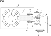
- FIG. 1 is a schematic diagram of a film-forming device.
- a film-forming device roughly comprises plasma generating means 1, a plasma duct 2 which is a transport route of evaporated particles formed by vaporizing a cathode material by the plasma generating means, and a film-forming chamber 3 for forming a film.
- the plasma generating means 1 includes a cathode part 11 and an anode part 12 arranged near the cathode part 11.
- the cathode part 11 and the anode part 12 are respectively connected to an external arc power source 13 by way of insulated feed-through terminals 4, thereby enabling an arc discharge.
- the cathode part 11 includes a cathode 11A formed of a film-forming material, and this cathode 11A corresponds to a target (a raw material of evaporated materials).
- a target a raw material of evaporated materials
- a film-forming material to be a target can be separately arranged on a surface of the cathode 11A.
- a constituent material of the cathode 11A serving also as a target can be any electrically conductive solid such as simple metals, alloys, simple inorganic substances, and inorganic compounds. These materials can be used singly or as a mixture of two or more.
- simple metals can be all of main group metals and transition metals.
- Typical examples of simple metals include Al, Ti, V, Cr, Fe, Co, Ni, Cu, Zn, Y, Zr, Nb, Ag, In, Sn, Sb, Hf, Pt, Au, Hg, Pb, Nd, Ta, W, and Mo.
- Examples of alloys and intermetallic compounds include TiAl, TiCr, TiSi, AlSi, AlCr, and NdFe.
- An example of simple inorganic substances is C(graphite).
- inorganic compounds examples include oxides such as TiO 2 , ZnO, SnO 2 , ITO (Indium Tin Oxide: tin-doped indium oxide), In 2 O 3 , Cd 2 SnO 4 , and CuO, carbides and nitrides such as TiN, TiAlC, TiC, CrN, and TiCN, and mixtures of two or more of them.
- Non-metal materials can be mixed in a range in which the cathode 11A keeps its electric conductivity (becomes semiconductive or metalloid), and are exemplified by B, C, Si, P, Ge, As, Se, Sb, Te, Bi, Po, At.
- an atmosphere gas examples include He, Ar, H 2 , N 2 , O 2 , fluoride gas, hydrocarbon gas, chloride gas, sulfide gas and a mixture thereof.
- Gas or vapor of liquid containing fluorine, hydrogen, carbon, chlorine, sulfur, boron, phosphorus, etc. can be introduced into an atmosphere.
- the anode part 12 can be any conductive material which withstands temperature of about 200° C such as simple metals, alloys, simple inorganic substances, and inorganic compounds.
- the material of the anode part 12 can be appropriately selected from the listed examples of the cathode material. These materials can be used singly or as a mixture of two or more.
- stainless steel, soft iron, steel, copper, copper alloys, aluminum, aluminum alloys, and graphite can be used as the anode part 12.
- a trigger electrode 14 is arranged near the aforementioned cathode 11A, and induces a vacuum arc between the cathode part 11 and the anode part 12. That is to say, when the trigger electrode 14 is temporarily contacted with a surface of the cathode 11A and then separated, an electric spark is generated between the cathode 11A and the trigger electrode 14. When the electric spark occurs, electric resistance decreases between the cathode part 11 and the anode part 12 and a vacuum arc is generated between the cathode part 11 and the anode part 12.
- An arc-stabilizing magnetic field generator 15 is arranged around the cathode part 11. The arc-stabilizing magnetic field generator 15 serves to stabilize cathode spots of the vacuum arc and plasma generated by the arc discharge.
- the arc-stabilizing magnetic field generator 15 can be located inside the chamber, or behind the cathode part. A plurality of arc-stabilizing magnetic field generators 15 can be arranged. The arc-stabilizing magnetic field generator 15 only need to apply a magnetic field, which stabilizes cathode spots and an arc discharge and efficiently transports a plasma flow, to a surface of the cathode and/or a front of the cathode.
- a region to be a transport route of evaporated particles is formed inside the anode part 12 having a roughly tubular shape.
- a magnetic field generator 21 comprising an electromagnet is arranged on an outer periphery of the roughly tubular anode part 12, and generates an induced magnetic field for guiding charged particles formed by evaporation of a film-forming material to move in a predetermined direction. This induced magnetic field is oriented along a central axis of the roughly tubular anode part 12.
- the charged particles in the region to be a transport route are guided along the central axis of the roughly tubular anode part 12 in a straight line direction from the cathode part 11.
- the charged particles are supplied to an object A to be treated in the film-forming chamber 3 through an opening 31 of the film-forming chamber 3 arranged in front. Since this transport route is straight line, a distance from the cathode part 11 to the object A to be treated can be small.
- the film-forming chamber 3 has the opening 31 on a side facing the plasma generating means 1, and also has object-holding means 32 for holding objects A, B, ..., H to be treated on an inside. Upon rotated intermittently, the object-holding means 32 can make the plurality of objects A to H to be treated sequentially face the plasma generating means 1 and be subjected to a film-forming process.
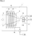
- FIG. 2 shows a structure of plasma generating means 1 of the present embodiment.
- a protection member 5 provided on an anode side constituting the plasma generating means 1 are a protection member 5, and an electromagnetic coil (an electric field generator) 21 electrically connected with the protection member 5.
- the electromagnetic coil 21 is connected to a positive electrode side of an arc power source and enables an arc discharge between the cathode part 11 and the protection member 5.
- the protection member 5 has a roughly tubular shape and is formed of an electrically conductive material such as non-magnetic stainless steel, copper or copper alloys.
- the electromagnetic coil 21 is arranged to wind around the roughly tubular protection member 5.
- the protection member 5 and the electromagnetic coil 21 are electrically connected to each other at ends on a far side from the cathode part 11 by a connector 51.
- An end of the electromagnetic coil 21 at a farthest position from the connector 51 is connected to the positive electrode side of the arc powder source.
- the protection member 5 and the electromagnetic coil 21 both formed of electrically conductive materials are not in contact with each other in order not to electrically connect each other.
- the anode part 12 is constituted by the whole of the protection member 5 and the electromagnetic coil 21, but an anode contributing to generation of an arc discharge is constituted by a local part of the protection member 5.
- the protection member 5 serves as an anode.
- the protection member 5 serves to protect the electromagnetic coil (magnetic field generator) 21. That is to say, the protection member 5 is arranged inside the electromagnetic coil 21 and arc plasma X flows inside the protection member 5. Thus, the protection member 5 is arranged between the plasma flow and the electromagnetic coil 21.
- evaporated particles and droplets contained in emitted materials are also emitted, unionized particles (neutral particles) and droplets among them are emitted in straight line directions without affected by a magnetic field of the electromagnetic coil 21. Therefore, the unionized particles and the droplets are emitted also at some angles (in directions of the arrows in the drawing) to the central axis of the electromagnetic coil 21 regardless of a plasma flow (a transport route of evaporated particles).
- the protection member 5 protects the electromagnetic coil 21 from the neutral particles and the droplets thus emitted.
- the electromagnetic coil 21 is located outside the protection member 5, so the electromagnetic coil 21 is protected from attachment of evaporated particles (reacted particles with introduced gas) other than neutral particles and ions which are not greatly affected by the magnetic field, etc.
- Neutral particles and droplets among cathode emitted materials which have reached an inner surface of the protection member 5 are attached to the inner surface of the protection member 5 just like attached to an object to be treated in forming a film. Therefore, emitted neutral particles and droplets except those moving along the central axis of the electromagnetic coil 21, that is to say, neutral particles and droplets emitted at some angles to the central axis can be removed by attached to the protection member 5. Therefore, the emitted neutral particles and the droplets can be prevented from attached to the magnetic field generator in itself. Moreover, since the droplets are attached to the protection member 5, the number of droplets reaching an object to be treated can be decreased. How to remove droplets generated in forming a DLC film (unattachable droplets) will be mentioned later.
- the entire anode is constituted by the protection member 5 and the electromagnetic coil 21, that is to say, the role of a local anode is played by the protection member 5 and at the same time, a magnetic field is generated by applying an electric current to the electromagnetic coil 21. Therefore, a distance from the cathode part 11 to the object to be treated can be greatly decreased, and this can reduce a decrease in density of the evaporated materials formed by an arc discharge and improve a rate of forming a film.
- an annular protection member 6 and a distal end annular member 7 each having an appropriate dimensional difference between an outer diameter and an inner diameter and having a predetermined thickness are arranged at both ends (an end on a cathode part side and an end on its opposite side) of an electromagnetic coil 21.
- the protection member 6 has a surface having a predetermined area in a radial direction of the electromagnetic coil 21 and a surface having a predetermined area in an inner circumferential direction.
- the inside of the annular protection member 6 have an inner diameter which arc plasma X barely passes through.
- the protection member 6 aims to protect the electromagnetic coils 21 by receiving attachment of evaporated particles and droplets and at the same time aims to suppress the droplets from reaching an object to be treated by these two surfaces, and therefore, enlargement of these two surfaces contributes to prevention of the evaporated particles and the droplets from attached to the electromagnetic coil 21.
- the protection member 6 arranged on a cathode part side has a surface facing the cathode part 11 and an inner circumferential surface which are located on a closer side to the cathode part 11 than the electromagnetic coil 21. Therefore, the evaporated particles and the droplets can be attached to these two surfaces before reaching the electromagnetic coil 21, thereby suppressed from reaching the electromagnetic coil 21.
- the distal end annular member 7 located at an opposite side to the cathode part side receives attachment of the evaporated particles and the droplets which have passed the electromagnetic coil 21. Since this distal end annular member 7 also has a surface facing the cathode part 11 and an inner circumferential surface (an inner circumferential surface in particular) and purposefully allows at least droplets to be attached to these surfaces, the distal end annular member 7 inhibits passage of the droplets emitted toward these surfaces and suppresses the droplets from reaching an object to be treated.
- the protection member 6 and the distal end annular member 7 are formed of electrically conductive materials.
- the distal end annular member 7 located on the opposite side to the cathode part side can serve as an anode at the time of an arc discharge.
- electrons generated at the cathode 11A mainly move to the protection member 6 formed of the electrically conductive material, as shown by the dashed arrows.
- connection to the positive electrode of the power source (a power source connector 16) is preferably located at a farthest position from the cathode part 11 of the electromagnetic coil 21.
- some evaporated particles (including reacted particles with introduced gas) and droplets may pass through someplace between the protection member 6 and the distal end annular member 7 (indicated by the arrow Y in Fig. 3(a) ).
- Some of this kind of evaporated particles and droplets are assumed to be attached to part of the electromagnetic coil 21. In order to prevent this, it is assumed to be effective to reduce an inner diameter of the protection member 6 on the cathode part side.
- a cathode material is graphite, etc. (a DLC film is to be formed)
- droplets are not attached to the protection member 6, the distal end annular member 7 or the electromagnetic coil 21 but bounded back (reflected) after collision.
- the protection member 6 and the distal end annular member 7 can be provided in order to control a transport direction of the droplets so that the droplets do not move toward an object to be treated. That is to say, the protection member 6 and the distal end annular member 7 reflect droplets containing a graphite material and guide the droplets to directions other than toward the object to be treated.
- droplets which have not collided with the protection member 6 but have passed through the protection member 6 are reflected by a surface of the electromagnetic coil 21 or are passed through gaps of the electromagnetic coil 21 and eventually guided in directions other than toward the object to be treated.
- the protection member 6 on the cathode part side can be omitted, though evaporated particles are attached to the electromagnetic coil 21.
- the distal end annular member 7 serving as an anode can have a hollow annular inner part 71, and cooling water can be introduced to the hollow annular inner part 71 to cool the anode side (the distal end annular member 7 can be a water-cooling ring member).
- This cooling structure helps to avoid a rise in temperature on the anode side at the time of an arc discharge.
- the protection member 6 on the cathode part side serves as an anode
- the protection member 6 can have a hollow annular inner part 61 and be similarly cooled.
- both the protection member 6 and the distal end annular member 7 can have hollow annular inner parts 61, 71, respectively, and be cooled with water.
- an annular protection member 6 (not necessarily a perfect circle and possibly a circle with a notch) can be continuously connected to one end (maybe both ends) of a roughly tubular protection member 5, and provided with a hollow annular inner part 61, thereby enabling water cooling.
- the roughly tubular protection member 5 serves as an anode, but its heat can be absorbed by the annular protection member 6 connected to the roughly tubular protection member 5.
- a distal end annular member 7 (See Fig. 3(a) ) having a roughly annular shape can be arranged on an opposite side to cool an anode side.
- the electromagnetic coil 21 can comprise a hollow member and water can be introduced into its hollow inner part.
- a roughly tubular protection member 5 is formed integrally with a protection member 6 and a distal end annular member 7 at both ends thereof.
- “Integrally” means not only a monolithically molded product but also a product formed by physically combining component parts. When employing such an integrally formed product, the roughly tubular protection member 5 and the protection member 6 on a cathode part side can protect an electromagnetic coil 21.
- connection to a positive electrode of an electric power source (a power source connector 16) is located at part of the electromagnetic coil 21 close to a cathode.
- a power source connector 16 connection to a positive electrode of an electric power source
- an anode side contributes to an arc discharge, and at the same time a rise in temperature of the anode (especially the protection member 6) by the arc discharge can be reduced. This contributes to efficient generation of arc plasma.
- a third embodiment according to the present invention is a magnetic field generator comprising plate members assembled in a roughly spiral shape instead of the aforementioned electromagnetic coil 21. That is to say, although the electromagnetic coil 21 is formed of an electrically conductive material in a coil (spiral) shape, a roughly spiral shape is formed by placing a plurality of electrically conductive plate members in parallel and sequentially connecting these members by an electrically conductive material.
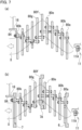
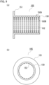
- Figs. 5 show the magnetic field generator of the present embodiment.
- Fig. 5(a) is an exploded perspective view
- Fig. 5(b) is a perspective view of the entire magnetic field generator.
- individual electrically conductive plate members 80a-80e constituting a magnetic field generator 8 have a roughly horse-shoe shape in which part of a ring is notched (expressed also as a C-shape), and two ends 82a-82e, 83a-83e are respectively formed on both sides of each notch 81a-81e.
- All of the plate members 80a-80e having the same shape are arranged in parallel to each other and each adjacent two of the plate members 80a-80e are electrically connected.
- Examples of an electrically conductive material of the plate members include stainless steel, copper, copper alloys, aluminum, aluminum alloys, and graphite.
- Positions of the notches 81a-81e of the parallel plate members 80a-80e are sequentially varied by a predetermined angle between each adjacent two of the plate members 80a-80e.
- This angle adjustment changes positions of the ends 82a-82e, 83a-83e on both sides of the notches 81a-81e.
- one end 82b of the second plate member 80b faces the other end 83a of the first plate member 80a.
- the two ends 83a, 82b on facing different sides are combined by a fastening member 9, whereby the adjacent two plate members 80a, 80b can be electrically connected to each other.
- the fastening member 9 comprises not only a typical bolt 91 and a typical nut 92 but also a tubular electrically conductive part 93 formed of an electrically conductive material.
- the electrically conductive part 93 When the electrically conductive part 93 is arranged between the adjacent two plate members 80a, 80b, the electrically conductive part 93 electrically connects the adjacent two plate members 80a, 80b, while keeping an appropriate distance between them.
- all the plate members 80a-80e as a whole form a roughly tubular magnetic field generator 8.
- a plasma flow can flow inside (through a central hole of) the roughly annular magnetic field generator 8.
- an electric current flows in the same direction as a circumferential direction of the respective plate members 80a-80e, and sequentially moves from one to a subsequent one of the plate members 80a-80e by way of facing adjacent two kinds of ends 82a-82e, 83a-83e, making a roughly spiral shape.
- the plate members 80a-80e can generate a magnetic field just like an electromagnetic coil, and can guide a plasma flow in a direction along a central axis of the magnetic field generator 8.
- a reference sign 51 designates a connector to the protection member and a reference sign 84 designates a connector to a positive electrode side of the arc power source.
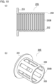
- the magnetic field generator 8 When the magnetic field generator 8 having the above structure is used, as shown in Figs. 6 , the magnetic field generator 8 can be protected by the aforementioned protection member 5 (see Fig. 6(a) ) or the annular protection member 6 (see Fig. 6(b) ). Note that in Figs. 6 , the number of plate members are increased to 80a-80k in order to show a shape of the magnetic field generator 8 and dimensional ratios of component parts are not considered.
- a connector 51 for connection to the protection member 5 is connected to a plate member 80k on one end, and a plate member 80a on the other end is connected to a positive electrode of an arc power source.
- annular protection member 6 such as that of the second embodiment
- the protection member 6 should be arranged on a cathode part side.
- a similar member (a distal end annular member) 7, and another similar member (an intermediate annular member) 7A can be respectively provided at a distal end (an opposite side to the cathode part) and an intermediate position of the magnetic field generator 8.
- the annular members 6, 7, and 7A can have hollow annular inner parts and allow cooling water to be introduced into the hollow annular inner parts.
- protection of the magnetic field generator 8 from evaporated particles and droplets by the annular protection member 6 is effected by a surface of the annular protection member 6, but it is easily predicted that some evaporated particles and droplets which have passed through the protection member 6 are also attached to the plate members 80a-80k. Any of the plate members 80a-80k can be provided with a cooling mechanism.
- the plate members 80a-80k can be easily separated by releasing the fastening members 9, and an operation to remove (or clean) attached materials from the separated individual plate members 80a-80k can be easily conducted.
- the removing operation can be done mechanically, for example, by lathing or shot blasting. Chemical removal using chemical agents is also easy.
- the tubular protection member 5 shown in Fig. 6(a) can be easily cleaned of the attached materials. Since each component part is small, the each component part can also be easily subjected to ultrasonic cleaning.
- a fourth embodiment uses roughly horse-shoe-shaped plate members 80a-80k such as mentioned above, and sequentially displaces positions of the plate members 80a-80k in a radial direction of a central hole.
- the displaced states are shown in Figs. 7 .
- all of the individual plate members 80a-80k have the same roughly horse-shoe shape, and similarly to the third embodiment, each adjacent two of the plate members 80a-80k are electrically connected by fastening members 9. Therefore, the plate member 80a-80k as a whole can pass an electric current in a roughly spiral shape. In addition to this, the individual plate members 80a-80k are sequentially displaced in a radial direction.
- a subsequent plate member 80b is radially elevated with respect to a first plate member 80a, and such displacement is repeated.
- a sixth plate member 80f in a middle is located at a highest position and then a seventh plate member 80g to a last plate member 80k are sequentially lowered.
- a generated magnetic field makes a flow of arc plasma X (plasma flow) meander.
- neutral particles and droplets move straight, and therefore the neutral particles and the droplets emitted from the cathode 11A collide with surfaces of the individual plate members 80a-80k.
- the plate members 80a-80k are formed of a material to which droplets are attachable, droplets are attached to the surfaces of the plate members 80a-80k.
- the plate members 80a-80k are formed of a material which bounces back (or reflects) droplets, the droplets are bounced back by the surfaces of the plate members 80a-80k and cannot move forward toward an object to be treated.
- the first plate member 80a receives collision of a greatest number of neutral particles and droplets, and neutral particles and droplets which have passed through the first plate member 80a collide with the second plate member 80b. Therefore, collision of the droplets is concentrated on part of the plate members 80a-80f on a first half of the entire magnetic field generator 8. Especially when a center hole of a plate member 80f in a middle position does not overlap that of the first plate member 80a due to individual displacement conditions, neutral particles and droplets do not reach a second half, i.e., the plate members 80g-80k.
- part of the magnetic field generator 8 (the first half 80a-80f) can protect other parts of the magnetic field generator 8 (the second half 80g-80k). Accordingly, attached neutral particles and droplets can be collected by regularly replacing the first half 80a-80f of the plate members with new ones.
- the aforementioned structure shown in Fig. 7(a) does not employ a protection member apart from the magnetic field generator 8
- part of the magnetic field generator 8 (the plate members 80a-80f arranged on the cathode side) serves as a protection member (substitutes a protection member).
- the first plate member 80a can serve as an anode.
- the magnetic field generator 8 can generate a magnetic field by a self current (an electron current) of an arc discharge.
- annular protection member 6 can be arranged on the cathode side, as shown in Fig. 7(b) .
- annular members with the same structure (a distal end annular member and a middle annular member) 7 and 7A can be additionally arranged at a distal end (an opposite side to a cathode part side) and at a middle position. Then cooling water can be introduced to their hollow annular inner parts. Since temperature remarkably increases at a bent part of a plasma flow, it is especially preferable to provide water-cooling annular members at these three bent parts (see Fig. 7(b) ).
- the magnetic field generator 8 is used as an anode part, and at the same time, part of the magnetic field generator 8 serves as a protection member. Moreover, a magnetic field generated by the magnetic field generator 8 makes a plasma flow meander. However, since an extra distance necessary for meandering is very small, a distance from the cathode part 11 to an object to be treated can be decreased eventually. This achieves reduction of a decrease in density of evaporated materials formed by an arc discharge and an improvement in film-forming rate.
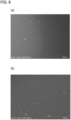
- a cathode material was titanium (Ti) and serving as an anode were 15 sheets of horse-shoe-shaped plate members formed of oxygen-free copper.
- the plate members had inner diameters within the range of 100 mm to 150 mm changing gradually from 100 mm around a center to 150 mm at both ends.
- the whole of the horse-shoe-shape magnetic field generator had a magnetic flux density of about 6 mT.
- An arc current was 110 A.
- An atmosphere gas was N 2 , which was introduced at a flow rate of 30 sccm.
- a chamber internal pressure (a film-forming pressure) was 0.3 Pa and thickness of a film to be formed was adjusted to about 1.8 ⁇ m.
- a distance between a cathode part and an object to be treated in a film-forming device was about 350 mm.
- FIG. 8(a) A surface of a TiN film formed under the above conditions was observed using a scanning electron microscope. Its result is shown in Fig. 8(a) .
- a film of the same thickness was formed by using a tubular anode which did not generate a magnetic field and a surface of the film was also observed using the scanning electron microscope. Its result is shown in Fig. 8(b) .
- a comparison of these SEM images in Figs. 8(a), and 8(b) clearly shows that attachment of droplets onto surfaces of films having the same film thickness is remarkably different between these two.
- Figs. 9 show a modification of the protection member 5 in the first embodiment.
- Fig. 9(a) is its longitudinal cross-sectional view and Fig. 9(b) is its side view.
- a plurality of projections 152 are formed on an inner surface 150B of a tubular main body 150 of a protection member 105 and thus make the inner surface 150B uneven. Uneven means that the inner surface 150B clearly become bumpy by providing the projections 152 when compared to an outer surface 150A.
- this protection member 105 is used to bounce back (or reflect) droplets emitted from a cathode without attached on a surface thereof. That is to say, when the inner surface 150B is even and smooth, it is predicted that droplets which have collided with the surface are reflected and move toward an object to be treated. However, when the inner surface 150B has a plurality of projections 152, there is a very high possibility that droplets collide with any of the projections 152. As a result, reflection angle of droplets which have collided with any of the projections 152 is greatly changed, so a ratio of droplets moving toward the object to be treated can be decreased. When droplets collide with any of the projections 152, collision with part of a surface on a cathode side is common and the droplets are supposed to be reflected backward.
- the inner surface 150B can be made uneven by forming dents in place of these projections 152.
- the protection member 105 can be provided with an outwardly extending part (a flange part) at one end of the main body 150 and the outwardly extending part can be used as a connector 151 to a magnetic field generator (an electromagnetic coil, etc.) surrounding the outer periphery of the main body 150.
- this outwardly extending part (the flange part) can be increased in ring thickness and have a hollow annular inner part for permitting cooling water to be introduced.
- FIG. 10(a) Another modification is a protection member 205 having a structure shown in Fig. 10(a) .
- projections 252 on an inner surface 250B of a main body 250 have an annular shape. This structure, too, can change directions to reflect droplets which have collided with the inner surface 250B.
- the annular projections shown in Fig. 10(a) can be replaced with spiral projections.
- the annular projections can be replaced with annular grooves.
- a flange part 251 can have the same structure as that of the above modification.
- a still another modification is a protection member 305 having a structure shown in Fig. 10(b) .
- a main body 350 has a plurality of through holes 353.
- these through holes 353 are formed long in a generating line direction of the tubular main body 350, these through holes can be short and have a circular or other shapes.
- the long through holes 353 are shown as an example.
- a flange 351 in this modification can also be used as a connector to an electromagnetic coil, etc. or can have a hollow annular inner part which permits cooling water to be introduced.
- the magnetic field generators 21 and 8 for guiding a plasma flow generates a magnetic field by an electric current of an arc discharge generated by plasma generating means. Therefore, a structure from the cathode part 11 to the film-forming chamber 3 can be reduced in size and distance when compared to a structure in which the magnetic field generator and plasma generating means are separately provided. In such a small distance, the droplets are attached to the protection member 5, 6 and/or the distal end annular member 7, or directions to bounce back the droplets are controlled by a surface of the protection member 5, 105, 205, or 305. Thus, at least droplets can be suppressed from reaching the film-forming chamber 3.
- Figs. 11 are longitudinal cross-sectional views.
- the annular protection member 6 and the distal end annular member 7 can have smaller inner diameters than the tubular protection member 5, thereby decreasing a ratio of droplets attached to an inner surface of the tubular protection member 5.
- collision of droplets, etc. with the tubular protection member 5 can be decreased ( Fig. 11(a) ) and droplets which have passed the tubular protection member 5 and move toward an object to be treated can be further decreased ( Figs. 11(a), 11(b) ).
- tubular protection members 5 can have projections 152 and 252 as in the aforementioned modifications. It should be noted that when the annular protection member 6 is used as shown in Fig. 11(a) but does not serve as an anode (or a power source connector 16), the annular protection member 6 is not electrically connected to the tubular protection member 5 or the electromagnetic coil 21. Specifically, the annular protection member 6 is separated from the tubular protection member 5 or the tubular electromagnetic coil 21, or is insulated. When the protection member 6 is formed of an electrically non-conductive material, the tubular protection member 5 and the annular protection member 6 can be physically connected to each other.
- vapor deposits can be easily removed.
- the vapor deposits can be mechanically removed by lathing or shot blasting.
- the vapor deposits can also be easily removed by chemicals.
- shapes of the coiled structures shown in Figs. 3 and 4 can be bent as shown in Figs. 7 .
- an anode screen can be provided between an anode and plasma. Since a structure of the anode screen is described in detail in Japanese Unexamined Patent Application Publication No. H05-247630 , drawings are omitted here. In this case, the anode screen has a great number of small-diameter holes. When the anode screen is thus provided, most of an electrically insulating film material in forming a film is deposited on the anode screen and only a small part leaked out from the small-diameter holes of the anode screen is deposited on the anode.
- the electrically insulating film material is not deposited on part of the anode shaded by the anode screen except the small-diameter holes, and thus the anode is avoided from covered with the electrically insulating film material.
- an arc current an electron current of a vacuum arc discharge
- An example of this type of anode screen is a punching metal formed of stainless steel, but others can be used.
Landscapes
- Chemical & Material Sciences (AREA)
- Engineering & Computer Science (AREA)
- Physics & Mathematics (AREA)
- Plasma & Fusion (AREA)
- Analytical Chemistry (AREA)
- Materials Engineering (AREA)
- Chemical Kinetics & Catalysis (AREA)
- Mechanical Engineering (AREA)
- Metallurgy (AREA)
- Organic Chemistry (AREA)
- Spectroscopy & Molecular Physics (AREA)
- Plasma Technology (AREA)
- Physical Vapour Deposition (AREA)
Applications Claiming Priority (1)
| Application Number | Priority Date | Filing Date | Title |
|---|---|---|---|
| PCT/JP2022/017073 WO2023195058A1 (ja) | 2022-04-04 | 2022-04-04 | 成膜装置 |
Publications (2)
| Publication Number | Publication Date |
|---|---|
| EP4506484A1 true EP4506484A1 (de) | 2025-02-12 |
| EP4506484A4 EP4506484A4 (de) | 2025-04-23 |
Family
ID=88242648
Family Applications (1)
| Application Number | Title | Priority Date | Filing Date |
|---|---|---|---|
| EP22936458.3A Pending EP4506484A4 (de) | 2022-04-04 | 2022-04-04 | Vorrichtung zur filmherstellung |
Country Status (6)
| Country | Link |
|---|---|
| US (1) | US20250210320A1 (de) |
| EP (1) | EP4506484A4 (de) |
| JP (1) | JPWO2023195058A1 (de) |
| KR (1) | KR20240152366A (de) |
| CN (1) | CN118786239A (de) |
| WO (1) | WO2023195058A1 (de) |
Families Citing this family (2)
| Publication number | Priority date | Publication date | Assignee | Title |
|---|---|---|---|---|
| WO2025187067A1 (ja) * | 2024-03-08 | 2025-09-12 | 国立大学法人豊橋技術科学大学 | 真空アーク蒸着用の蒸発源装置および真空アーク蒸着装置 |
| CN119811976B (zh) * | 2025-03-17 | 2025-06-27 | 温州职业技术学院 | 直管磁过滤径向电弧源 |
Family Cites Families (10)
| Publication number | Priority date | Publication date | Assignee | Title |
|---|---|---|---|---|
| JP3254721B2 (ja) | 1992-03-05 | 2002-02-12 | 日新電機株式会社 | 真空アーク蒸着装置 |
| DE19739527C2 (de) * | 1997-09-09 | 2003-10-16 | Rossendorf Forschzent | Vakuumbogen-Plasmaquelle mit Magnet-Partikelfilter |
| JP3865570B2 (ja) | 2000-06-16 | 2007-01-10 | 伊藤光学工業株式会社 | プラズマ加工法 |
| JP4000764B2 (ja) * | 2000-09-18 | 2007-10-31 | 日新電機株式会社 | 真空アーク蒸発装置 |
| US20020070647A1 (en) * | 2000-12-11 | 2002-06-13 | Andrey Ginovker | Nanostructure plasma source |
| JP4319556B2 (ja) | 2004-01-28 | 2009-08-26 | 浩史 滝川 | プラズマ生成装置 |
| JP4889957B2 (ja) * | 2005-03-25 | 2012-03-07 | 株式会社フェローテック | プラズマ生成装置におけるドロップレット除去装置及びドロップレット除去方法 |
| JP4660452B2 (ja) * | 2006-09-30 | 2011-03-30 | 株式会社フェローテック | 拡径管型プラズマ生成装置 |
| JP5189784B2 (ja) * | 2007-03-30 | 2013-04-24 | 株式会社フェローテック | プラズマガン周辺を電気的中性にしたプラズマ生成装置 |
| JP6121576B1 (ja) * | 2016-01-07 | 2017-04-26 | キヤノンアネルバ株式会社 | 成膜装置 |
-
2022
- 2022-04-04 US US18/849,892 patent/US20250210320A1/en active Pending
- 2022-04-04 JP JP2024513586A patent/JPWO2023195058A1/ja active Pending
- 2022-04-04 CN CN202280093473.3A patent/CN118786239A/zh active Pending
- 2022-04-04 KR KR1020247031127A patent/KR20240152366A/ko active Pending
- 2022-04-04 WO PCT/JP2022/017073 patent/WO2023195058A1/ja not_active Ceased
- 2022-04-04 EP EP22936458.3A patent/EP4506484A4/de active Pending
Also Published As
| Publication number | Publication date |
|---|---|
| EP4506484A4 (de) | 2025-04-23 |
| WO2023195058A1 (ja) | 2023-10-12 |
| CN118786239A (zh) | 2024-10-15 |
| JPWO2023195058A1 (de) | 2023-10-12 |
| KR20240152366A (ko) | 2024-10-21 |
| US20250210320A1 (en) | 2025-06-26 |
Similar Documents
| Publication | Publication Date | Title |
|---|---|---|
| CN104364416B (zh) | 过滤阴极电弧沉积设备和方法 | |
| EP1055013B1 (de) | Kathodenbogendampfphasenbeschichtung | |
| US5580429A (en) | Method for the deposition and modification of thin films using a combination of vacuum arcs and plasma immersion ion implantation | |
| JP6625793B2 (ja) | 減圧アークプラズマ浸漬皮膜蒸着及びイオン処理 | |
| EP0811236B1 (de) | Vorrichtung und Verfahren zu filtern von Makropartikeln aus einem Plasmastrahl | |
| EP4506484A1 (de) | Vorrichtung zur filmherstellung | |
| US7867366B1 (en) | Coaxial plasma arc vapor deposition apparatus and method | |
| US6635156B1 (en) | Producing electric arc plasma in a curvilinear plasmaguide and substrate coating | |
| CA2758137C (en) | Arc evaporation source and film forming method using the same | |
| EP0511153A1 (de) | Vorrichtung zur Plasmaanhebung und Verfahren zur physikalischen Dampfabscheidung | |
| US20070187229A1 (en) | Filtered cathodic-arc plasma source | |
| US8038858B1 (en) | Coaxial plasma arc vapor deposition apparatus and method | |
| US20020070647A1 (en) | Nanostructure plasma source | |
| JP2009543951A (ja) | 電気絶縁皮膜の堆積方法 | |
| EP1862565B1 (de) | Tröpfchenentfernungsvorrichtung und -verfahren in plasmagenerator | |
| CN102471869B (zh) | 阳极壁多分割型等离子发生装置及等离子处理装置 | |
| JP2851320B2 (ja) | 真空アーク蒸着装置及び方法 | |
| US20030193031A1 (en) | Filtered ion source | |
| US12503756B2 (en) | Apparatus and method for coating the inner surface of a hollow article | |
| US9624570B2 (en) | Compact, filtered ion source | |
| RU2173911C2 (ru) | Получение электродуговой плазмы в криволинейном плазмоводе и нанесение покрытия на подложку | |
| EP1081247A2 (de) | Vorrichtung zum Lichtbogenionenplattieren | |
| Beilis | Vacuum Arc Plasma Sources. Thin Film Deposition | |
| Anders | Cathodic arc sources | |
| Ensinger et al. | Homogeneous Coating of the Inner Walls of Metal Tubes by Ion Beam Sputter Deposition |
Legal Events
| Date | Code | Title | Description |
|---|---|---|---|
| STAA | Information on the status of an ep patent application or granted ep patent |
Free format text: STATUS: THE INTERNATIONAL PUBLICATION HAS BEEN MADE |
|
| PUAI | Public reference made under article 153(3) epc to a published international application that has entered the european phase |
Free format text: ORIGINAL CODE: 0009012 |
|
| STAA | Information on the status of an ep patent application or granted ep patent |
Free format text: STATUS: REQUEST FOR EXAMINATION WAS MADE |
|
| 17P | Request for examination filed |
Effective date: 20240912 |
|
| AK | Designated contracting states |
Kind code of ref document: A1 Designated state(s): AL AT BE BG CH CY CZ DE DK EE ES FI FR GB GR HR HU IE IS IT LI LT LU LV MC MK MT NL NO PL PT RO RS SE SI SK SM TR |
|
| A4 | Supplementary search report drawn up and despatched |
Effective date: 20250326 |
|
| RIC1 | Information provided on ipc code assigned before grant |
Ipc: H01J 37/32 20060101ALI20250320BHEP Ipc: C23C 14/32 20060101ALI20250320BHEP Ipc: C23C 14/24 20060101AFI20250320BHEP |
|
| DAV | Request for validation of the european patent (deleted) | ||
| DAX | Request for extension of the european patent (deleted) |