EP4502437A1 - Steuerventil und herstellungsverfahren dafür - Google Patents
Steuerventil und herstellungsverfahren dafür Download PDFInfo
- Publication number
- EP4502437A1 EP4502437A1 EP23778157.0A EP23778157A EP4502437A1 EP 4502437 A1 EP4502437 A1 EP 4502437A1 EP 23778157 A EP23778157 A EP 23778157A EP 4502437 A1 EP4502437 A1 EP 4502437A1
- Authority
- EP
- European Patent Office
- Prior art keywords
- connecting portion
- valve
- valve seat
- housing
- base
- Prior art date
- Legal status (The legal status is an assumption and is not a legal conclusion. Google has not performed a legal analysis and makes no representation as to the accuracy of the status listed.)
- Pending
Links
Images


Classifications
-
- F—MECHANICAL ENGINEERING; LIGHTING; HEATING; WEAPONS; BLASTING
- F16—ENGINEERING ELEMENTS AND UNITS; GENERAL MEASURES FOR PRODUCING AND MAINTAINING EFFECTIVE FUNCTIONING OF MACHINES OR INSTALLATIONS; THERMAL INSULATION IN GENERAL
- F16K—VALVES; TAPS; COCKS; ACTUATING-FLOATS; DEVICES FOR VENTING OR AERATING
- F16K27/00—Construction of housing; Use of materials therefor
- F16K27/06—Construction of housing; Use of materials therefor of taps or cocks
-
- F—MECHANICAL ENGINEERING; LIGHTING; HEATING; WEAPONS; BLASTING
- F16—ENGINEERING ELEMENTS AND UNITS; GENERAL MEASURES FOR PRODUCING AND MAINTAINING EFFECTIVE FUNCTIONING OF MACHINES OR INSTALLATIONS; THERMAL INSULATION IN GENERAL
- F16K—VALVES; TAPS; COCKS; ACTUATING-FLOATS; DEVICES FOR VENTING OR AERATING
- F16K5/00—Plug valves; Taps or cocks comprising only cut-off apparatus having at least one of the sealing faces shaped as a more or less complete surface of a solid of revolution, the opening and closing movement being predominantly rotary
- F16K5/08—Details
-
- B—PERFORMING OPERATIONS; TRANSPORTING
- B23—MACHINE TOOLS; METAL-WORKING NOT OTHERWISE PROVIDED FOR
- B23K—SOLDERING OR UNSOLDERING; WELDING; CLADDING OR PLATING BY SOLDERING OR WELDING; CUTTING BY APPLYING HEAT LOCALLY, e.g. FLAME CUTTING; WORKING BY LASER BEAM
- B23K31/00—Processes relevant to this subclass, specially adapted for particular articles or purposes, but not covered by any single one of main groups B23K1/00 - B23K28/00
- B23K31/02—Processes relevant to this subclass, specially adapted for particular articles or purposes, but not covered by any single one of main groups B23K1/00 - B23K28/00 relating to soldering or welding
-
- B—PERFORMING OPERATIONS; TRANSPORTING
- B23—MACHINE TOOLS; METAL-WORKING NOT OTHERWISE PROVIDED FOR
- B23P—METAL-WORKING NOT OTHERWISE PROVIDED FOR; COMBINED OPERATIONS; UNIVERSAL MACHINE TOOLS
- B23P19/00—Machines for simply fitting together or separating metal parts or objects, or metal and non-metal parts, whether or not involving some deformation; Tools or devices therefor so far as not provided for in other classes
- B23P19/04—Machines for simply fitting together or separating metal parts or objects, or metal and non-metal parts, whether or not involving some deformation; Tools or devices therefor so far as not provided for in other classes for assembling or disassembling parts
-
- F—MECHANICAL ENGINEERING; LIGHTING; HEATING; WEAPONS; BLASTING
- F16—ENGINEERING ELEMENTS AND UNITS; GENERAL MEASURES FOR PRODUCING AND MAINTAINING EFFECTIVE FUNCTIONING OF MACHINES OR INSTALLATIONS; THERMAL INSULATION IN GENERAL
- F16K—VALVES; TAPS; COCKS; ACTUATING-FLOATS; DEVICES FOR VENTING OR AERATING
- F16K27/00—Construction of housing; Use of materials therefor
- F16K27/06—Construction of housing; Use of materials therefor of taps or cocks
- F16K27/067—Construction of housing; Use of materials therefor of taps or cocks with spherical plugs
-
- F—MECHANICAL ENGINEERING; LIGHTING; HEATING; WEAPONS; BLASTING
- F16—ENGINEERING ELEMENTS AND UNITS; GENERAL MEASURES FOR PRODUCING AND MAINTAINING EFFECTIVE FUNCTIONING OF MACHINES OR INSTALLATIONS; THERMAL INSULATION IN GENERAL
- F16K—VALVES; TAPS; COCKS; ACTUATING-FLOATS; DEVICES FOR VENTING OR AERATING
- F16K27/00—Construction of housing; Use of materials therefor
- F16K27/10—Welded housings
- F16K27/107—Welded housings for taps or cocks
-
- F—MECHANICAL ENGINEERING; LIGHTING; HEATING; WEAPONS; BLASTING
- F16—ENGINEERING ELEMENTS AND UNITS; GENERAL MEASURES FOR PRODUCING AND MAINTAINING EFFECTIVE FUNCTIONING OF MACHINES OR INSTALLATIONS; THERMAL INSULATION IN GENERAL
- F16K—VALVES; TAPS; COCKS; ACTUATING-FLOATS; DEVICES FOR VENTING OR AERATING
- F16K5/00—Plug valves; Taps or cocks comprising only cut-off apparatus having at least one of the sealing faces shaped as a more or less complete surface of a solid of revolution, the opening and closing movement being predominantly rotary
- F16K5/06—Plug valves; Taps or cocks comprising only cut-off apparatus having at least one of the sealing faces shaped as a more or less complete surface of a solid of revolution, the opening and closing movement being predominantly rotary with plugs having spherical surfaces; Packings therefor
- F16K5/0663—Packings
- F16K5/0689—Packings between housing and plug
-
- B—PERFORMING OPERATIONS; TRANSPORTING
- B23—MACHINE TOOLS; METAL-WORKING NOT OTHERWISE PROVIDED FOR
- B23P—METAL-WORKING NOT OTHERWISE PROVIDED FOR; COMBINED OPERATIONS; UNIVERSAL MACHINE TOOLS
- B23P15/00—Making specific metal objects by operations not covered by a single other subclass or a group in this subclass
- B23P15/001—Making specific metal objects by operations not covered by a single other subclass or a group in this subclass valves or valve housings
Definitions
- the present application relates to technical field of fluid control, and in particular to a manufacturing method for a control valve.
- FIG. 1 shows a cross-sectional schematic diagram of a ball valve in conventional technology.
- the ball valve includes a valve body tube 01, a left valve body 02, a right valve body 03, a left pipe 04, a right pipe 05, a valve rod 06 and a valve core 07.
- the valve body tube 01 is welded to the left valve body 02 and the right valve body 03.
- the valve rod 06 is used to cooperate with the keyway of the valve core 07, and the valve rod 06 can drive the valve core 07 to rotate circumferentially.
- a left mounting groove 021 is machined on the left valve body 02
- a right mounting groove 031 is machined on the right valve body 03
- the left pipe 04 is welded to the left mounting groove 021 for positioning
- the right pipe 05 is welded to the right mounting groove 031 for positioning.
- the valve body structure is relatively complex and inconvenient to machine.
- the matching position relationships of the left valve body 02, the right valve body 03 and the valve body tube 01 are related to the pre-tightening force of the left valve body 02, the right valve body 03 applied on the valve core 07, which may affect the rotational torque of the valve rod 06 applied on the valve core 07.
- the purpose of the present application is to provide a control valve, which includes a housing, a first valve seat and a first connecting pipe.
- the first valve seat is formed by stamping or stretching a metal.
- the first valve seat includes a first base, a first connecting portion and a second connecting portion.
- the first base is annular, the first connecting portion is tubular, the first connecting portion extends from an outer edge of the first base toward the housing, the second connecting portion is tubular, the second connecting portion extends from the inner edge of the first base toward the first connecting pipe side, the housing is fixedly connected to the first connecting portion, and the first connecting pipe is fixedly connected to the second connecting portion.
- the control valve provided in the present application includes the housing, the first valve seat and the first connecting pipe.
- the first valve seat is formed by stamping or stretching a metal, including the first connecting portion and the second connecting portion.
- the housing is fixedly connected to the first connecting portion, and the first connecting pipe is fixedly connected to the second connecting portion.
- the first valve seat structure of the present application is simple.
- the purpose of the present invention is to provide a method for manufacturing a control valve, including:
- the manufacturing method of the control valve provided by the present invention welds and fixes the first connecting portion to the first connecting pipe as the first valve seat connecting pipe assembly, welds and fixes the third connecting portion to the second connecting pipe as the second valve seat connecting pipe assembly, and assembles the housing, the first valve seat connecting pipe assembly, and the second valve seat connecting pipe. This solution facilitates the control of the matching position of the first valve seat, the second valve seat, and the housing during welding.
- FIG. 2 is a cross-sectional schematic diagram of a control valve provided by the application;
- FIG. 3A is a partial enlarged schematic diagram of I1 in FIG. 2 ;
- FIG. 4 is a three-dimensional diagram of a first valve seat in FIG. 2 .
- the control valve includes a housing 1, a first valve seat 2, a connector 3, a first pipe 4, and a valve rod 5.
- the first valve seat 2 is formed by stamping or stretching a metal.
- the first valve seat 2 is specifically made by stamping or stretching a metal plate.
- the first valve seat 2 includes a first base 21, a first connecting portion 22, and a second connecting portion 23.
- the first base 21 is of an annular shape
- the first connecting portion 22 is of a tubular shape
- the first connecting portion 22 is formed by an outer edge of the first base 21 extending towards the housing 1.
- the second connecting portion 23 is of a tubular shape, and the second connecting portion 23 is formed by an inner edge of the first base 21 extending towards the first connecting pipe 4, that is, the first connecting portion 22 and the second connecting portion 23 are located on different sides of the first base 21. Further, the first connecting portion 22 and the second connecting portion 23 are coaxially arranged, that is, a central axis of the first connecting portion 22 coincides with a central axis of the second connecting portion 23, and an inner diameter of the first connecting portion 22 is larger than an outer diameter of the second connecting portion 23.
- the housing 1 is fixedly connected to the first connecting portion 22 by welding or threading, and the first connecting pipe 4 is fixedly connected to the second connecting portion 23 by welding or threading. Specifically, the housing 1 is fixed to the first connecting portion 22 by laser welding, and the first pipe 4 is fixed to the second connecting portion 23 by furnace welding.
- the first valve seat 2 is made by stamping or stretching of a metal plate.
- the first valve seat 2 includes a first connecting portion 22 and a second connecting portion 23, the housing 1 is fixedly connected to the first connecting portion 22, and the first pipe 4 is fixedly connected to the second connecting portion 23.
- the valve seat structure of this embodiment is simple, does not require machining, and is easy to process.
- the control valve also includes a valve core 6 and a first sealing gasket 7.
- the valve core 6 is roughly of a spherical shape and is located in the valve cavity 10 of the control valve.
- the first valve seat 2 includes an inner step portion 24 with a step surface facing the valve core 6, and the inner step portion 24 includes a first base 21 and a first connecting portion 22.
- the first sealing gasket 7 is placed on the inner step portion 24, and the first sealing gasket 7 abuts against the valve core 6 to support the valve core 6.
- the inner step portion 24 formed by stamping or stretching of the first valve seat 2 supports the first sealing gasket 7 and the valve core 6, and has a simple structure.
- the inner step portion 24 has a groove 20, which is located at a connection between the first base 21 and the first connecting portion 22 and is formed by stamping.
- the groove 20 has an inclined angle, so that the first sealing gasket 7 can reliably match with the first valve seat 2, thereby improving the matching accuracy of the first sealing gasket 7 and the first valve seat 2.
- the first sealing gasket 7 includes a chamfered portion 71, the chamfered surface of the chamfered portion 71 faces the connection between the first base 21 and the first connecting portion 22, and the chamfered portion 71 can also enable the first sealing gasket 7 to reliably match with the first valve seat 2.
- the first sealing gasket 7 also includes a first accommodating groove 70, the opening of which faces the first base 21.
- the control valve also includes a first sealing ring 9, which is made of a rubber material and has elasticity.
- the first sealing ring 9 is located in the first accommodating groove 70, and the first sealing ring 9 abuts against the groove wall forming the first accommodating groove 70, and the first sealing ring 9 abuts against the first base 21, that is, the first sealing ring 9 is elastically located between the groove wall of the first accommodating groove 70 and the first base 21.
- the first connecting pipe 4 includes a first matching section 41, and the first matching section 41 is mounted outside the second connecting portion 23.
- the second connecting portion 23 includes a convex portion 231, which is formed by a wire drawing process, and the convex portion 231 is located on an outer peripheral surface of the second connecting portion 23.
- the first matching section 41 is welded and fixed to the convex portion 231 after matching.
- the housing 1 is formed by stamping or stretching of a stainless steel pipe, and includes a main body 11 and a protrusion 12.
- the protrusion 12 protrudes from a circumferential outer wall of the main body 11.
- the main body 11 is of a cylindrical shape, and the protrusion 12 is of an annular shape.
- the first connecting portion 22 is at least partially located in the inner cavity 110 of the main body.
- An outer peripheral wall of the first connecting portion 22 is in clearance fit with an inner wall of the housing 1.
- the main body 11 and the first connecting portion 22 are welded and fixed.
- a joint 3 includes an outer step part 33 with a step surface facing downward (toward the valve core 3).
- the protrusion 12 is contacted and positioned with the step surface of the outer step part 33.
- the step wall of the outer step part 33 is located in the inner cavity 120 of the protrusion.
- the protrusion 12 is welded and fixed with the outer step part 33.
- the protrusion 12 is contacted with the step surface of the outer step part 33 to achieve positioning, thereby improving the positioning accuracy of the joint 3 and the housing 1, and facilitating the welding of the joint 3 and the housing 1.
- the joint 3 is roughly of an annular shape and is formed by lathe machining of stainless steel profiles.
- the connector 3 includes a through hole 30, the valve rod 5 is inserted into the through hole 30, the lower section of the valve rod 5 extends into the valve cavity 10 of the control valve and is connected to a keyway of the valve core 6, and the valve rod 5 can drive the valve core 6 to rotate to open or close the control valve or adjust the flow of the control valve.
- the connector 3 includes a lower step portion 32 which is integrally formed, and the valve rod 5 includes a valve rod step portion 54 with the step surface facing upward, and the valve rod step portion 54 can abut against the lower step portion 32 to limit the valve rod 5 from moving upward along a longitudinal direction of the control valve.
- the valve rod 5 is an inverted structure, and the lower step portion 32 can reliably limit the valve rod 5; and the lower step portion 32 is arranged on the connector 3, and the valve rod 5 can achieve a reliable limiting without providing a flange portion protruding outward, which can reduce a material cost of the valve rod 5.
- the housing 1, the first valve seat 2 and the first connecting pipe 4 are made of stainless steel.
- the housing 1 and the joint 3 are fixed by laser welding, the first valve seat 2 and the first connecting pipe 4 are fixed into an assembly by furnace welding, and then the first valve seat 2 is fixed to the housing 1 by laser welding.
- FIG. 5 is a three-dimensional view of the second valve seat in FIG. 2 .
- the control valve also includes a second valve seat 2', a second connecting pipe 4' and a second sealing gasket 7'.
- the second valve seat 2' has the same structure as the first valve seat 2, is made of a metal sheet by stamping or stretching, and is symmetrically arranged relative to the central axis of the protrusion 12 of the housing 1.
- the second valve seat 2' includes a second base 21', a third connecting portion 22' and a fourth connecting portion 23', the second base 21' is of an annular shape, the third connecting portion 22' is of a tubular shape, the third connecting portion 22' extends from the outer edge of the second base 21' toward the housing 1, and the fourth connecting portion 23' is of a tubular shape, and the fourth connecting portion 23' extends from the inner edge of the second base 21' toward the second pipe 4'.
- the housing 1 is connected to the third connecting portion 22' by welding or threading, and the second pipe 4' is connected to the fourth connecting portion 23' by welding or threading. With this arrangement, the structure of the second valve seat 2' is simple.
- the second pipe 4' includes a second matching section 41', the second matching section 41' is mounted outside the fourth connecting portion 23', and the second matching section 41' is welded and fixed to the fourth connecting portion 23'.
- the second sealing gasket 7' has the same structure as the first sealing gasket 7 and is symmetrically arranged relative to the central axis of the protrusion 12.
- the valve core 6 is located between the first sealing gasket 7 and the second sealing gasket 7', the second valve seat 2' supports the second sealing gasket 7', and the second sealing gasket 7' supports the valve core 6.
- FIG. 3B is a partial enlarged schematic diagram of I2 in FIG. 2 ;
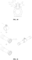
- FIG. 6 is an assembly schematic diagram of the first valve seat connecting pipe assembly A;
- FIG. 7 is an assembly schematic diagram of the first assembly part D;
- FIG. 8 is an assembly schematic diagram of the stop ring, the joint and the housing;
- FIG. 9 is an assembly schematic diagram of the third assembly part C;
- FIG. 10 is a cross-sectional schematic diagram of the third assembly part C;
- FIG. 11 is an assembly schematic diagram of the third assembly part C with the first assembly part D and the second assembly part E.
- the housing 1 includes a body 11 and a protruding portion 12.
- the stainless steel pipe is cut into a housing blank, and then the housing blank is stamped and flanged to produce the protruding portion 12.
- the housing blank is stamped and flanged to produce the protruding portion 12.
- it can also be made of stainless steel sheet.
- the stainless steel sheet needs to be rolled into a tube, and the subsequent process is the same as the tube.
- the first valve seat 2 and the second valve seat 2' are made of stainless steel sheet by stamping, and the first valve seat 2 and the second valve seat 2' have the same structure. Specifically, the stainless steel sheet is punched out of a "Z"-shaped structure as the first valve seat 2.
- the first valve seat 2 includes the first base 21, the first connecting portion 22 and the second connecting portion 23.
- the first base 21 is of an annular shape
- the first connecting portion 22 is of a tubular shape
- the first connecting portion 22 extends from the outer edge of the first base 21 to one side.
- the second connecting portion 23 is of a tubular shape, and the second connecting portion 23 extends from the inner edge of the first base 21 to the other side, that is, the first connecting portion 22 and the second connecting portion 23 are located on different sides of the first base 21, and the inner diameter of the first connecting portion 22 is larger than the outer diameter of the second connecting portion 23.
- the first base 21 and the first connecting portion 22 form an inner step 24.
- a "Z"-shaped structure is punched out of a stainless steel plate as the second valve seat 2'.
- the second valve seat 2' includes the second base portion 21', the third connecting portion 22' and the fourth connecting portion 23'.
- the second base portion 21' is of an annular shape
- the third connecting portion 22' is of a tubular shape
- the third connecting portion 22' extends from the outer edge of the second base portion 21' toward one side
- the fourth connecting portion 23' is of a tubular shape
- the fourth connecting portion 23' extends from the inner edge of the second base portion 21' toward the other side, that is, the third connecting portion 22' and the fourth connecting portion 23' are located on different sides of the second base portion 21'
- the inner diameter of the third connecting portion 22' is larger than the outer diameter of the fourth connecting portion 23'.
- the first valve seat 2 and the second valve seat 2' do not need to be machined after stamping, which can reduce a processing cost of the first valve seat 2 and the second valve seat 2'.
- the first pipe 4 and the second pipe 4' are specifically made of stainless steel pipes.
- One end of the specific first pipe 4 forms a first matching section 41 through a flaring process.
- the other end of the first pipe 4 is used to weld a copper bushing, which can be covered or embedded in the other end of the first pipe 4.
- the second pipe 4' has the same structure as the first pipe 4 and is not repeated.
- a first sealing gasket 7 and a second sealing gasket 7' are provided, and the first sealing gasket 7 and the second sealing gasket 7' are made of PTFE, PEK, high-temperature nylon and other materials.
- the joint 3 is roughly hollow cylindrical and includes a through hole 30.
- the joint 3 includes an upper step portion 31 with a step surface facing upward, a lower step portion 32 with a step surface facing downward, and an outer step portion 33 with a step surface facing downward located on periphery.
- the outer step portion 33 is located in a lower section of the joint 3, and an outer peripheral wall of an upper section of the joint 3 is processed with an external thread portion 33.
- a stop ring 8 is provided, and the stop ring 8 is stamped from a stainless steel plate and includes a matching hole 80.
- the valve rod 5 includes a cylindrical portion 51, a first key portion 52 and a second key portion 53, the first key portion 52 is located on an upper portion of the cylindrical portion 51, and the second key portion 53 is located on a lower portion of the cylindrical portion 51.
- the cylindrical portion 51 includes a valve rod step portion 54 with a step surface facing upward.
- valve bonnet 100 is specifically made of stainless steel, and an inner circumferential wall of the valve bonnet 100 is machined with an internal threaded portion 101.
- the first valve seat 2, the first connecting pipe 4 and the first copper bushing 200 are fixedly connected by furnace brazing as a first valve seat connecting pipe assembly A.
- the first connecting portion 22 of the first valve seat 2 at least partially extends into the first matching section 41 of the first connecting pipe 4, and the first copper bushing 200 is covered or embedded in the other end of the first connecting pipe 4, and the first valve seat 2, the first connecting pipe 4 and the first copper bushing 200 are fixed by furnace brazing.
- the second valve seat 2', the second connecting pipe 4' and the second copper bushing 200' are fixedly connected by furnace brazing as a second valve seat connecting pipe assembly B.
- the third connecting portion 22' of the second valve seat 2' at least partially extends into the second matching section 41' of the second connecting pipe 4', and the second copper bushing 200' is covered or embedded in the other end of the second connecting pipe 4', and the three are fixed by furnace brazing.
- the first valve seat connecting pipe assembly A and the second valve seat connecting pipe assembly B can be interchanged.
- the lower section of the joint 3 is extended into the inner cavity 120 of the protruding portion, so that a step surface 331 of the outer step portion 33 contacts the protruding portion 12, and the step wall 332 of the outer step portion 33 is located in the inner cavity 120 of the protruding portion, and the joint 3 is fixedly connected to the housing 1 by laser welding; the stop ring 8 is placed on the upper step portion 31 of the joint 3, and the stop ring 8 is fixedly connected to the joint 3 by laser welding.
- the valve rod 5 is assembled, specifically, the valve rod 5 is installed from an opening end of the housing 1 at one side, so that the valve rod 5 passes through the through hole 30 of the joint 3, and the valve rod step portion 54 can abut against the lower step portion 32 of the joint 3 to limit the valve rod 5 from moving longitudinally upward and coming out.
- the first key portion 52 extends out of the connector 3, which is convenient for external tool wrenches to rotate.
- a valve core 6 is provided, which is made of stainless steel.
- the valve rod 5 is rotated until an extension direction of the second key portion 53 is consistent with an axial direction of the main body 11, and then the valve core 6 is installed from the opening end of the housing 1 at one side, so that the second key portion 53 and the groove 60 of the valve core 6 are embedded to form a third assembly part C, that is, the third assembly part C includes the housing 1, the connector 3, the stop ring 8, the valve rod 5 and the valve core 6.
- the housing 1, the first valve seat connecting pipe assembly A, and the second valve seat connecting pipe assembly B are assembled. Specifically, the second connecting portion 23 of the first valve seat 2 at least partially extends into the housing 1, and the second connecting portion 23 is welded and fixed to the housing 1; the fourth connecting portion 23' of the second valve seat 2' at least partially extends into the housing 1, and the fourth connecting portion 23' is welded and fixed to the housing 1.
- this solution is convenient for controlling the matching position accuracy of the first valve seat, the second valve seat and the housing during the welding process, so that the valve core is subjected to the same pre-tightening force of the first valve seat and the second valve seat, thereby improving the consistency of the rotation torque of the valve rod on the valve core.
- control valve also includes a first sealing ring 9 and a second sealing ring 9', the first sealing ring 9 and the second sealing ring 9' are made of rubber material, the first sealing gasket 7 is provided with a first accommodating groove 70, an opening of the first accommodating groove 70 faces the first base 21, and before the second connecting portion 23 of the first valve seat 2 is welded to the housing 1, the first sealing ring 9 is placed in the first accommodating groove 70 and assembled as a component with the first valve seat connecting pipe assembly A to form a first assembly part D. Specifically, the first sealing gasket 7 is placed in the inner step portion 24 of the first valve seat 2, so that the outer peripheral wall of the first sealing gasket 7 is tightly matched with the inner peripheral wall of the second connecting portion 23.
- the second sealing gasket 7' has the same structure as the first sealing gasket 7, and the second sealing gasket 7' is provided with a second accommodating groove 70'.
- the second sealing ring 9' is placed in the second accommodating groove 70' and assembled with the second valve seat connecting pipe assembly B as a component to form a second assembly part E, so that the outer peripheral wall of the second sealing gasket 7' is tightly matched with the inner peripheral wall of the fourth connecting portion 23'.
- the specific assembly method is the same as the assembly method of the first assembly part D.
- the joint 3 of the third assembly part C is positioned by the tooling, and the first assembly part D and the second assembly part E are clamped by a synchronous actuating mechanism (such as a servo, etc.).
- the first assembly part D is clamped with the outer wall 211 of the first base 21 of the first valve seat 2 as a positioning surface
- the second assembly part E is clamped with the outer wall 211' of the second base 21' of the second valve seat 2' as a positioning surface.
- the first assembly part D and the second assembly part E are simultaneously moved towards the valve core 6 by a preset distance.
- the first valve seat 2 partially extends into the inner cavity 110 of the main body, the first sealing gasket 7 abuts against the valve core 6, and the second valve seat 2' partially extends into the inner cavity 110 of the main body, so that the second sealing gasket 7' abuts against the valve core 6 to achieve pre-positioning.
- the first valve seat 2 is fixedly connected to the housing 1 by laser welding
- the second valve seat 2' is fixedly connected to the housing 1 by laser welding. It is conceivable that the first valve seat 2 and the second valve seat 2' can also be welded to the housing 1 at the same time by laser. In this way, the assembly accuracy of the control valve can be improved, the consistency of the rotation torque of the valve rod on the valve core can be improved, and the internal leakage performance of the control valve can be improved.
- housing 1 and the first valve seat 2 and the second valve seat 2' can also be fixed by welding methods such as argon arc welding and gas shielded welding.
- valve bonnet 100 is screwed into the joint 3 to form the control valve, and the valve bonnet 100 is fixedly connected to the joint 3 by screwing the external threaded portion 34 with the internal threaded portion 101.
- the first connecting portion 22 is formed into the convex portion 231 by a wire drawing process, and the first matching section 41 is matched with the convex portion 231 for welding.
- the convex portion 231 in this solution is conducive to the flow of solder, which can improve the welding reliability of the first valve seat 2 and the first connecting pipe 4.
- connection structure of the second valve seat 2' and the second connecting pipe 4' can also adopt the connection structure of the first valve seat 2 and the first connecting pipe 4, which also has the corresponding technical effect, and is not repeated here.
- the first sealing gasket 7 includes a chamfered portion 71, and the chamfered portion 71 faces the connection between the first base 21 and the second connecting portion 23, so that the R angle at the connection between the first base 21 and the second connecting portion 23 can be avoided, and the matching reliability between the first valve seat 2 and the first sealing gasket 7 can be ensured.
- the first valve seat 2 is formed with a groove 20 by stamping, and the groove 20 is located at the connection between the first base 21 and the second connecting portion 23, which can also ensure the matching reliability between the first valve seat 2 and the first sealing gasket 7.
- the matching structure of the second valve seat 2' and the second sealing gasket 7' can also adopt the matching structure of the first valve seat 2 and the first sealing gasket 7, which also has the corresponding technical effect, and is not repeated here.
- each component is basically made of stainless steel material, which meets the requirements of the lead content of control products in today's society; the first copper bushing, the first connecting pipe and the first valve seat are fixed by one-time welding, the process is simple, and the processing is convenient; the connection is fixed by furnace brazing and laser welding, and no pickling is required, and the production process is clean and environmentally friendly.
Landscapes
- Engineering & Computer Science (AREA)
- General Engineering & Computer Science (AREA)
- Mechanical Engineering (AREA)
- Valve Housings (AREA)
Applications Claiming Priority (5)
| Application Number | Priority Date | Filing Date | Title |
|---|---|---|---|
| CN202220733494 | 2022-03-31 | ||
| CN202210333693 | 2022-03-31 | ||
| CN202221573072.1U CN217784267U (zh) | 2022-03-31 | 2022-06-21 | 一种控制阀 |
| CN202210704038.1A CN116921995A (zh) | 2022-03-31 | 2022-06-21 | 一种控制阀的制造方法 |
| PCT/CN2023/084264 WO2023185792A1 (zh) | 2022-03-31 | 2023-03-28 | 一种控制阀及其制造方法 |
Publications (2)
| Publication Number | Publication Date |
|---|---|
| EP4502437A1 true EP4502437A1 (de) | 2025-02-05 |
| EP4502437A4 EP4502437A4 (de) | 2026-04-08 |
Family
ID=88199141
Family Applications (1)
| Application Number | Title | Priority Date | Filing Date |
|---|---|---|---|
| EP23778157.0A Pending EP4502437A4 (de) | 2022-03-31 | 2023-03-28 | Steuerventil und herstellungsverfahren dafür |
Country Status (5)
| Country | Link |
|---|---|
| US (1) | US20250224039A1 (de) |
| EP (1) | EP4502437A4 (de) |
| JP (1) | JP7842242B2 (de) |
| KR (1) | KR20240167915A (de) |
| WO (1) | WO2023185792A1 (de) |
Families Citing this family (2)
| Publication number | Priority date | Publication date | Assignee | Title |
|---|---|---|---|---|
| JP2025107004A (ja) * | 2024-01-05 | 2025-07-17 | 東京エレクトロン株式会社 | ガスボックス及び半導体製造装置 |
| CN119870947B (zh) * | 2025-03-26 | 2025-06-03 | 江苏江沅机械有限公司 | 一种截止阀阀杆与阀芯同步装配机 |
Family Cites Families (23)
| Publication number | Priority date | Publication date | Assignee | Title |
|---|---|---|---|---|
| GB1038614A (en) * | 1963-02-19 | 1966-08-10 | Shafer Homer John | Ball valve construction |
| US3348804A (en) * | 1964-06-10 | 1967-10-24 | Grove Valve & Regulator Co | Valve construction |
| US3841601A (en) * | 1971-04-19 | 1974-10-15 | M & J Valve Co | Fabricated ball valve |
| JPS50108024U (de) * | 1974-02-12 | 1975-09-04 | ||
| JPS5462529A (en) * | 1977-10-28 | 1979-05-19 | Nippon Carbon Co Ltd | Valve seat |
| JPS57121460U (de) * | 1981-01-23 | 1982-07-28 | ||
| JPS601323Y2 (ja) * | 1982-02-13 | 1985-01-16 | 株式会社クボタ | 弁のシ−ル構造 |
| US6643929B2 (en) * | 2000-11-16 | 2003-11-11 | Tix Corporation | Method of producing ball valve |
| JP4194527B2 (ja) | 2004-05-18 | 2008-12-10 | 株式会社勇鉄工所 | チタン製ボールバルブ |
| US20080203723A1 (en) | 2007-02-22 | 2008-08-28 | Conbraco Industries, Inc. | Detachable pipe joint and joining method |
| CN201258978Y (zh) * | 2008-09-08 | 2009-06-17 | 诸暨市恒森冷热器材有限公司 | 制冷球阀 |
| CN101672379B (zh) * | 2008-09-08 | 2012-11-21 | 何永水 | 制冷球阀及其制作工艺 |
| CN202327194U (zh) * | 2011-11-22 | 2012-07-11 | 金荣伟 | 密封调节球阀 |
| CN104033616A (zh) * | 2013-03-05 | 2014-09-10 | 浙江三花股份有限公司 | 一种球阀及其组合方法 |
| CN203335984U (zh) * | 2013-05-06 | 2013-12-11 | 浙江盾安禾田金属有限公司 | 一种常闭型电磁阀 |
| CN204061974U (zh) * | 2014-09-12 | 2014-12-31 | 重庆特通阀门有限公司 | 对焊软密封球阀 |
| EP3470713B1 (de) * | 2016-06-08 | 2024-05-01 | Zhejiang Sanhua Intelligent Controls Co., Ltd. | Flussregelungsvorrichtung und verfahren zur herstellung davon |
| RU2680533C1 (ru) * | 2018-03-01 | 2019-02-22 | Дмитрий Олегович Левин | Шаровой кран и способ его изготовления |
| CN110725985B (zh) | 2018-07-17 | 2021-11-12 | 浙江三花制冷集团有限公司 | 一种电动球阀及其制造方法 |
| CN214036968U (zh) * | 2020-08-28 | 2021-08-24 | 浙江三花制冷集团有限公司 | 一种控制阀 |
| CN112161081A (zh) * | 2020-10-20 | 2021-01-01 | 符鹏 | 一种防冲刷球阀 |
| CN217784267U (zh) * | 2022-03-31 | 2022-11-11 | 浙江三花商用制冷有限公司 | 一种控制阀 |
| CN217784266U (zh) * | 2022-03-31 | 2022-11-11 | 浙江三花商用制冷有限公司 | 一种控制阀 |
-
2023
- 2023-03-28 WO PCT/CN2023/084264 patent/WO2023185792A1/zh not_active Ceased
- 2023-03-28 EP EP23778157.0A patent/EP4502437A4/de active Pending
- 2023-03-28 US US18/852,486 patent/US20250224039A1/en active Pending
- 2023-03-28 JP JP2024557120A patent/JP7842242B2/ja active Active
- 2023-03-28 KR KR1020247036339A patent/KR20240167915A/ko active Pending
Also Published As
| Publication number | Publication date |
|---|---|
| WO2023185792A1 (zh) | 2023-10-05 |
| EP4502437A4 (de) | 2026-04-08 |
| WO2023185792A9 (zh) | 2024-10-24 |
| JP2025510890A (ja) | 2025-04-15 |
| JP7842242B2 (ja) | 2026-04-07 |
| US20250224039A1 (en) | 2025-07-10 |
| KR20240167915A (ko) | 2024-11-28 |
Similar Documents
| Publication | Publication Date | Title |
|---|---|---|
| EP4502437A1 (de) | Steuerventil und herstellungsverfahren dafür | |
| JP4615175B2 (ja) | ボールバルブとその製造方法 | |
| JP7349514B2 (ja) | 電子膨張弁 | |
| JPWO2001057423A1 (ja) | ボールバルブとその製造方法 | |
| TWI451919B (zh) | Pinch device | |
| CN110735941A (zh) | 一种控制阀及其制造方法 | |
| CN112621164B (zh) | 压装方法、阀芯组件及电子膨胀阀 | |
| EP3044488B1 (de) | Ventilgehäuse mit einer spindelführung und verfahren zur herstellung davon | |
| CN116921995A (zh) | 一种控制阀的制造方法 | |
| JP2025518924A (ja) | 弁装置及びその製造方法 | |
| CN211588637U (zh) | 轴类零件径向孔加工用钻模 | |
| CN116251880A (zh) | 管件加工部件及管件加工设备 | |
| CN115807856A (zh) | 一种阀装置及其制造方法 | |
| CN223648601U (zh) | 球阀 | |
| JP4200158B2 (ja) | ガス器具 | |
| CN216201478U (zh) | 管件连接组件 | |
| CN100446920C (zh) | 一种管端封口方法 | |
| CN120502832B (zh) | 一种用于波纹管和阀杆的焊接工装及焊接设备 | |
| CN221610700U (zh) | 球阀 | |
| CN111702358A (zh) | 一种ct管钛窗螺钉焊接方法及焊接设备 | |
| CN219673440U (zh) | 一种新型结构的方体阀 | |
| CN120212260A (zh) | 一种控制阀和控制阀的制造方法 | |
| CN218269548U (zh) | 一种容器 | |
| CN215509490U (zh) | 用于加工具有深窄环形槽的组装式零件的工装 | |
| CN223359963U (zh) | 球阀 |
Legal Events
| Date | Code | Title | Description |
|---|---|---|---|
| STAA | Information on the status of an ep patent application or granted ep patent |
Free format text: STATUS: THE INTERNATIONAL PUBLICATION HAS BEEN MADE |
|
| PUAI | Public reference made under article 153(3) epc to a published international application that has entered the european phase |
Free format text: ORIGINAL CODE: 0009012 |
|
| STAA | Information on the status of an ep patent application or granted ep patent |
Free format text: STATUS: REQUEST FOR EXAMINATION WAS MADE |
|
| 17P | Request for examination filed |
Effective date: 20241010 |
|
| AK | Designated contracting states |
Kind code of ref document: A1 Designated state(s): AL AT BE BG CH CY CZ DE DK EE ES FI FR GB GR HR HU IE IS IT LI LT LU LV MC ME MK MT NL NO PL PT RO RS SE SI SK SM TR |
|
| DAV | Request for validation of the european patent (deleted) | ||
| DAX | Request for extension of the european patent (deleted) | ||
| A4 | Supplementary search report drawn up and despatched |
Effective date: 20260305 |
|
| RIC1 | Information provided on ipc code assigned before grant |
Ipc: F16K 27/06 20060101AFI20260227BHEP Ipc: F16K 5/06 20060101ALI20260227BHEP Ipc: F16K 27/10 20060101ALI20260227BHEP Ipc: B23P 15/00 20060101ALI20260227BHEP |