EP4501183A1 - Mikrowellen-popcornmaschine mit heizeinsatz - Google Patents
Mikrowellen-popcornmaschine mit heizeinsatz Download PDFInfo
- Publication number
- EP4501183A1 EP4501183A1 EP24179239.9A EP24179239A EP4501183A1 EP 4501183 A1 EP4501183 A1 EP 4501183A1 EP 24179239 A EP24179239 A EP 24179239A EP 4501183 A1 EP4501183 A1 EP 4501183A1
- Authority
- EP
- European Patent Office
- Prior art keywords
- heating insert
- heating
- main body
- base
- cover
- Prior art date
- Legal status (The legal status is an assumption and is not a legal conclusion. Google has not performed a legal analysis and makes no representation as to the accuracy of the status listed.)
- Pending
Links
Images


Classifications
-
- A—HUMAN NECESSITIES
- A47—FURNITURE; DOMESTIC ARTICLES OR APPLIANCES; COFFEE MILLS; SPICE MILLS; SUCTION CLEANERS IN GENERAL
- A47J—KITCHEN EQUIPMENT; COFFEE MILLS; SPICE MILLS; APPARATUS FOR MAKING BEVERAGES
- A47J36/00—Parts, details or accessories of cooking-vessels
- A47J36/02—Selection of specific materials, e.g. heavy bottoms with copper inlay or with insulating inlay
- A47J36/027—Cooking- or baking-vessels specially adapted for use in microwave ovens; Accessories therefor
-
- A—HUMAN NECESSITIES
- A23—FOODS OR FOODSTUFFS; TREATMENT THEREOF, NOT COVERED BY OTHER CLASSES
- A23L—FOODS, FOODSTUFFS OR NON-ALCOHOLIC BEVERAGES, NOT OTHERWISE PROVIDED FOR; PREPARATION OR TREATMENT THEREOF
- A23L7/00—Cereal-derived products; Malt products; Preparation or treatment thereof
- A23L7/10—Cereal-derived products
- A23L7/161—Puffed cereals, e.g. popcorn or puffed rice
- A23L7/174—Preparation of puffed cereals from wholegrain or grain pieces without preparation of meal or dough
- A23L7/183—Preparation of puffed cereals from wholegrain or grain pieces without preparation of meal or dough by heating without using a pressure release device
- A23L7/187—Discontinuously-working apparatus
-
- A—HUMAN NECESSITIES
- A23—FOODS OR FOODSTUFFS; TREATMENT THEREOF, NOT COVERED BY OTHER CLASSES
- A23L—FOODS, FOODSTUFFS OR NON-ALCOHOLIC BEVERAGES, NOT OTHERWISE PROVIDED FOR; PREPARATION OR TREATMENT THEREOF
- A23L5/00—Preparation or treatment of foods or foodstuffs, in general; Food or foodstuffs obtained thereby; Materials therefor
- A23L5/30—Physical treatment, e.g. electrical or magnetic means, wave energy or irradiation
- A23L5/34—Physical treatment, e.g. electrical or magnetic means, wave energy or irradiation using microwaves
-
- A—HUMAN NECESSITIES
- A23—FOODS OR FOODSTUFFS; TREATMENT THEREOF, NOT COVERED BY OTHER CLASSES
- A23P—SHAPING OR WORKING OF FOODSTUFFS, NOT FULLY COVERED BY A SINGLE OTHER SUBCLASS
- A23P30/00—Shaping or working of foodstuffs characterised by the process or apparatus
- A23P30/30—Puffing or expanding
- A23P30/38—Puffing or expanding by heating
-
- A—HUMAN NECESSITIES
- A47—FURNITURE; DOMESTIC ARTICLES OR APPLIANCES; COFFEE MILLS; SPICE MILLS; SUCTION CLEANERS IN GENERAL
- A47J—KITCHEN EQUIPMENT; COFFEE MILLS; SPICE MILLS; APPARATUS FOR MAKING BEVERAGES
- A47J36/00—Parts, details or accessories of cooking-vessels
- A47J36/02—Selection of specific materials, e.g. heavy bottoms with copper inlay or with insulating inlay
- A47J36/04—Selection of specific materials, e.g. heavy bottoms with copper inlay or with insulating inlay the materials being non-metallic
-
- A—HUMAN NECESSITIES
- A47—FURNITURE; DOMESTIC ARTICLES OR APPLIANCES; COFFEE MILLS; SPICE MILLS; SUCTION CLEANERS IN GENERAL
- A47J—KITCHEN EQUIPMENT; COFFEE MILLS; SPICE MILLS; APPARATUS FOR MAKING BEVERAGES
- A47J36/00—Parts, details or accessories of cooking-vessels
- A47J36/06—Lids or covers for cooking-vessels
-
- B—PERFORMING OPERATIONS; TRANSPORTING
- B65—CONVEYING; PACKING; STORING; HANDLING THIN OR FILAMENTARY MATERIAL
- B65D—CONTAINERS FOR STORAGE OR TRANSPORT OF ARTICLES OR MATERIALS, e.g. BAGS, BARRELS, BOTTLES, BOXES, CANS, CARTONS, CRATES, DRUMS, JARS, TANKS, HOPPERS, FORWARDING CONTAINERS; ACCESSORIES, CLOSURES, OR FITTINGS THEREFOR; PACKAGING ELEMENTS; PACKAGES
- B65D81/00—Containers, packaging elements, or packages, for contents presenting particular transport or storage problems, or adapted to be used for non-packaging purposes after removal of contents
- B65D81/34—Containers, packaging elements, or packages, for contents presenting particular transport or storage problems, or adapted to be used for non-packaging purposes after removal of contents for packaging foodstuffs or other articles intended to be cooked or heated within the package
- B65D81/3446—Containers, packaging elements, or packages, for contents presenting particular transport or storage problems, or adapted to be used for non-packaging purposes after removal of contents for packaging foodstuffs or other articles intended to be cooked or heated within the package specially adapted to be heated by microwaves
- B65D81/3453—Rigid containers, e.g. trays, bottles, boxes, cups
Definitions
- the present invention relates in general to devices for making popcorn in the home, and in particular those devices for use in microwave ovens.
- the reusable devices have taken one of two forms.
- the first is a glass container which is generally spherical but with a flat bottom for stability and an open top with removable cover.
- the second is a silicone receptacle in the general form of a cup, again with a removable cover. In both forms the user inserts kernels into the device, and then heats in the microwave to cause the popcorn to pop.
- An object of the present invention is to provide a microwave popcorn maker.
- Another object of the present invention is to provide a popcorn maker with improved performance.
- a further object of the present invention is to provide a popcorn maker including a heating insert for improved heating.
- a microwave popcorn maker with heating insert includes a main body in the form of a silicone cup. A removable plastic cover may close the open top end of the cup. A heating insert is located within the main body adjacent the base. The heating insert is formed of a material which absorbs microwave energy to heat faster than the material of the main body. The kernels for popping will rest upon the heating insert during heating in the microwave, and the increase heat absorption will result in improved popping performance. According to the present invention, there is provided a popcorn maker, comprising:
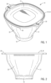
- a popcorn maker according to the present invention is generally designated by reference numeral 10.
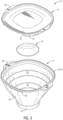
- the popcorn maker 10 generally includes a main body 12, a cover 14, and a heating insert 16. These will be described more fully below.
- the main body 12 takes the general form of a cup, with a base 18 having an outer periphery and one or more sidewalls 20 extending upward from the base 18 to an upper rim 22.
- the base is circular with a single side wall, but the base 18 may take a other geometric shapes having three or more sides, with a corresponding or similar number of sidewalls. These shapes may also be combined: in the embodiment shown the base 18 is round while the rim 22 is a rounded-corner square. It is also preferred that the sidewalls angle outward from the base such that the rim 22 is larger than base 18. This increases the volume of the main body (and thus the amount of food it may hold) and also makes the main body 12 easier to manually hold and carry.
- the upper rim 22 may include a radially extending flange 24 for additional structural strength. Upper rim 22 may further include a pair of peripherally opposed grip handles 24 extending radially outward such as from flange 24. These grip handles 24 may be seen to also make it easier to manually carry the main body 12, but serve other purposes as described below.
- the upper rim 22 preferably includes a depression which is sized and shaped to receive the peripheral edge of the cover 16.
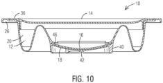
- the main body 12 is preferably formed of one or more elastomeric materials. In the preferred form, it is a monolithic body of silicone. This is similar to prior art devices, and provides high resistance to heat, impermeability to water (from condensed steam), butter, oils, and the like. Silicone is also easy to clean, and is relatively insulative to heat. The flexibility of silicone require sufficient thickness to ensure structural stability (a self-supporting structure even while hot). However, the flexibility of silicone allows the main body to be vertically collapsible from an operative configuration shown in Figs. 1-7 , and a collapsed configuration shown in Fig. 10 . The collapsed configuration will allow easier storage, as is known in the prior art.
- the sidewall 20 may include one or more peripherally extending flex bands 28, each having reduced thickness (and therefore reduced structural strength and increased flexibility) to allow and guide the movement of main body 12 into and out of the collapsed configuration. While a relatively abrupt transition step for the reduced thickness flex bands 28 are shown for clarity, in practice it is preferred to have a smoother transition of place the step on the exterior of sidewall 20 for easier cleaning.
- the cover 14 may be mounted upon the main body 12 by resting the cover 14 on the upper rim 22. When mounted to the main body 12, the cover 14 will close the opening in the main body 12 formed by upper rim 22 and help create an inner chamber for holding the food (for example unpopped kernels or popped corn). As illustrated in Fig. 3 , the cover 14 may be manually removed to access this inner chamber.
- the cover may be formed of a variety of materials, but a thermoplastic such as polypropylene is preferred.
- the cover 14 be in place during the heating of the popcorn maker 10, so as to prevent popping corn from exiting the main body 12. During this popping process, steam will be produced. To allow this steam to escape, it is preferred that one of the main body 12 or cover 14 include one or more apertures 30. It is also possible that each of the upper rim 22 and cover 14 include depressions which once aligned combine to form the apertures 30. In the preferred embodiment, the apertures 30 are located in the main body 12 just below the upper rim 22. As steam will exit the apertures, it is important to place the apertures 30 between the grip handles 26 to avoid steam contacting the user's hands.
- these apertures 30 it is preferred to allow these apertures 30 to be selectively closed.
- the apertures 30 should be open during the heating process, as noted, to allow steam to exit.
- the apertures 30 are preferably formed with a sufficiently small size or diameter that the popped corn will not freely exit the main body 12 via an aperture 30 during the heating process when the kernels are energetically popping. During this shaking process, the apertures 30 would again prevent the egress of the popcorn.
- the added ingredients may be of a size or form (such as a powder or a liquid) such that the apertures 30 would allow undesired egress during shaking.
- the cover 14 is formed with a partial skirt 32 extending downward from the lower face of cover 14, at a radial position to be closely adjacent (or touching) the inner face of sidewall 20, and with a vertical length sufficient to extend below and therefore block said apertures 30 when cover 14 rests upon the rim 22. In this way, the cover 14 may be placed to rest upon the upper rim 22 with the partial skirt 32 occluding the apertures 30.
- the partial skirt 32 is not continuous about the entire periphery of cover 14. Instead, the partial skirt 32 include a cutout 34 formed by a section of reduced vertical height, a section of reduced radial placement, or both. In the preferred embodiment, both are employed and it may be seen that cutout 34 is spaced radially inward relative to the remainder of partial skirt 32, and that cutout 34 has a reduced length compared to the remainder of partial skirt 32.
- the cutout 34 is of a length to correspond with the apertures 30 such that when cutout 34 overlies the apertures 30 then the apertures 30 are not occluded.
- the cutout 34 may be selective enabled or disabled by appropriate clocking placement of the cover 14 on main body 12.
- This selective clocking may be achieved in a variety of ways, such as indicia on the cover to indicate the position of the cutout 34; a geometric shape of the upper rim and partial skirt 32 which force only two cover clocking positions, etc.
- the upper rim 22 has the squared shape, and to achieve the desired close fit the partial skirt 32 has a similar squared shape. This would force clocking to one of four orientations.
- the cover 14 includes two opposed and radially extending cover handles 36 intended to overlie the grip handles 26. When used accordingly, this limits the clocking orientations of cover 14 to two: apertures closed; and apertures open.
- Figures 3 and 7 illustrate the apertures open position of cover 14.
- the cover 14 includes the indicia 38 noted above to illustrate the location of cutout 34. The user would thus orient the indicia 38 to overlie the apertures 30 when ready for heating. In the normal process, after heating the user would remove the cover after heating. If flavorings or additional ingredients are added to the food within the inner chamber, then the user would place the cover 14 back on the upper rim 22. This time, however, the cover would be oriented with the indicia 38 opposite (not overlying) the apertures 30. This would ensure the partial skirt 32 would occlude the apertures 30 during shaking.
- apertures 30 and skirt 32 may be further improved. It is known in the art that not all kernels will pop during heating. The un-popped kernels are undesirable in that they are unpalatable yet are sometimes consumed due to being present with the popped popcorn. This may be solved or alleviated by forming the apertures 30 of a sufficiently small size to prevent egress of typical popped popcorn, but of a sufficiently large size to allow egress of un-popped kernels. An individual aperture diameter of approximately 10mm has been found acceptable for this. In this way the cover 14 may be placed in the aperture-open position during heating to allow steam venting. Then immediately after heating the entire popcorn maker 10 may be inverted and manually shaken. During this process the overlying positions of the grip handles 26 and cover handles 36 allow the cover to remain easily in place. With this inverted shaking the un-popped kernels will fall towards and then through the apertures 30. The popcorn maker 10 would then be un-inverted.
- the cover 14 may be manually removed and set aside allowing the user to access the inner chamber.
- the food could then be seasoned and further shaken (apertures-closed) as described above.
- the cover 14 is then once again manually removed and set aside.
- the main body 12 could then be inverted to transfer the popped corn to a bowl for consumption. It is preferred, however, that the main body 12 be available for use as a serving bowl itself.
- the base 18 is preferably includes a base skirt 40 which serves to space the base 18 from any support upon which the base skirt 40 rests (including the user's body).
- the base skirt 40 may include one or more notches 42 at the free end thereof. These notches 42 allow air to enter and thus preclude any reduced pressure from forming below the base 18 and within base skirt 40 (which could occur as the popcorn maker 10 cools in the microwave after heating).
- One or more apertures (not shown) extending through the base skirt 42 would serve equally well to equalize pressure.
- the base 18 may further include one or more base ribs extending downward from base 18 and radially outward to base skirt 42. These ribs work with base skirt 42 to prevent direct contact of the user with base 18.
- a further aspect of the present invention is its most important. This improvement is the addition of the heating insert 16. While cup-shaped silicone receptacles with plastic covers are known in the prior art, the addition of the heating insert is believed a significant improvement.
- the heating insert 16 is received within main body 12, adjacent base 18, to define the inner chamber together with sidewalls 20 and cover 14.
- the heating insert 16 rests directly upon the base 18. This may be by full contact, or the base 18 may include one or more vent channels 44 ( Fig. 4 ) in its upper surface to allow steam to pass from beneath the heating insert 16.
- the heating insert 16 cover the inner face of the base 18 such that the periphery of the heating insert 16 coincides with the beginning of sidewall 20. For the preferred embodiment shown, this results in the heating insert 16 having a circular periphery.
- the heating insert 16 since the heating insert 16 overlies the base 18, the kernels intended to be heated will by gravity initially rest upon the heating insert 16 during heating.
- the heating insert 16 is formed of a substance providing greater microwave heat absorption compared to the material of which the main body 12 is formed.
- the heating insert 16 may take a variety of forms.
- One option is a microwave-safe ceramic, possibly coated with enamel or other similar material.
- a further option for heating insert 16 is a block containing susceptor powder similar to that shown in US10,244,586B2 to Barea (with an appropriate food-contact-safe coating).
- the preferred material is glass, and in particular borosilicate glass.
- the heating insert 16 is passive, but will absorb microwave energy during heating, thus serving to heat the kernels resting thereon. This is believe to increase the speed of popping, the percentage of kernels popped, and the repeatability of popping.
- the heating insert 16 will absorb more microwave energy, and heat faster and hotter, compared to the material of the main body 12. As such, the present invention adding the heating insert 16 will heat faster, hotter, and thus pop faster, pop a greater percentage of kernels, and with greater repeatability of popping, compared to a prior art device with kernels resting directly upon the silicone base.
- the presence alone of the heating insert 16 may improve performance; the shape of the heating insert 16 may further improve performance. While the heating insert 16 could be flat, it is preferred that it have a dished shape as shown in Figs. 6 and 7 .
- the dished shape (concave upwards) is believed to operate in several ways. The dished shape forces the kernels toward the center of the heating element 16, and away from the sidewalls 20; thus more kernels are in contact with the heating insert 16 versus sidewall 20.
- the dished shape also focuses radiant heat inward (toward the massed kernels) more effectively than a flat shape.
- the popcorn maker 10 include means for securing the heating insert 16 to the base 18. This may take a variety of forms.
- the upper face of the base 18 could have a suction cup (not shown) integrally and monolithically formed thereon to engage the lower face of the heating insert 16.
- the heating insert 16 could be glued (not shown) to the base 18.
- the sidewall 18 includes one or more locking ribs 46 extending radially inward to overlie the peripheral edge of the heating insert 16.
- the locking ribs 46 could also be monolithically formed, as shown in Figs. 6 and 7 . While a plurality of discrete fingers could be used, the embodiment shown uses a single locking rib 46 extending about and overlying the entire periphery of the heating insert 16. As may be envisioned, the locking rib 46 will serve to elastically retain the heating insert 16 in place upon the base 18. The elastic nature of the silicone will, however, allow the user to remove the heating insert 16 for washing and replace it thereafter.
Landscapes
- Engineering & Computer Science (AREA)
- Food Science & Technology (AREA)
- Life Sciences & Earth Sciences (AREA)
- Chemical & Material Sciences (AREA)
- Polymers & Plastics (AREA)
- Health & Medical Sciences (AREA)
- Nutrition Science (AREA)
- Mechanical Engineering (AREA)
- Cookers (AREA)
- Grain Derivatives (AREA)
- Electric Ovens (AREA)
Applications Claiming Priority (1)
| Application Number | Priority Date | Filing Date | Title |
|---|---|---|---|
| US18/227,954 US20250031901A1 (en) | 2023-07-30 | 2023-07-30 | Microwave popcorn maker with heating insert |
Publications (1)
| Publication Number | Publication Date |
|---|---|
| EP4501183A1 true EP4501183A1 (de) | 2025-02-05 |
Family
ID=91375008
Family Applications (1)
| Application Number | Title | Priority Date | Filing Date |
|---|---|---|---|
| EP24179239.9A Pending EP4501183A1 (de) | 2023-07-30 | 2024-05-31 | Mikrowellen-popcornmaschine mit heizeinsatz |
Country Status (7)
| Country | Link |
|---|---|
| US (1) | US20250031901A1 (de) |
| EP (1) | EP4501183A1 (de) |
| KR (1) | KR20250018454A (de) |
| CN (1) | CN119423255A (de) |
| AR (1) | AR132809A1 (de) |
| AU (1) | AU2024203619A1 (de) |
| MX (1) | MX2024007153A (de) |
Citations (2)
| Publication number | Priority date | Publication date | Assignee | Title |
|---|---|---|---|---|
| EP0022577A1 (de) * | 1979-07-13 | 1981-01-21 | Kabushiki Kaisha Toshiba | Kochgefäss für Mikrowellenofen |
| US8269154B2 (en) * | 2002-07-26 | 2012-09-18 | Ticona Llc | Ovenware for microwave oven |
-
2023
- 2023-07-30 US US18/227,954 patent/US20250031901A1/en active Pending
-
2024
- 2024-05-30 AR ARP240101365A patent/AR132809A1/es unknown
- 2024-05-30 AU AU2024203619A patent/AU2024203619A1/en active Pending
- 2024-05-31 EP EP24179239.9A patent/EP4501183A1/de active Pending
- 2024-06-11 MX MX2024007153A patent/MX2024007153A/es unknown
- 2024-07-24 KR KR1020240097650A patent/KR20250018454A/ko active Pending
- 2024-07-26 CN CN202411013331.9A patent/CN119423255A/zh active Pending
Patent Citations (2)
| Publication number | Priority date | Publication date | Assignee | Title |
|---|---|---|---|---|
| EP0022577A1 (de) * | 1979-07-13 | 1981-01-21 | Kabushiki Kaisha Toshiba | Kochgefäss für Mikrowellenofen |
| US8269154B2 (en) * | 2002-07-26 | 2012-09-18 | Ticona Llc | Ovenware for microwave oven |
Non-Patent Citations (1)
| Title |
|---|
| ANONYMOUS ZUM ET AL: "Amazon.de: Collapsible Silicone Microwave Hot Air Popcorn Popper Bowl with Lid and Handles (Red)", 25 January 2017 (2017-01-25), pages 1 - 10, XP093216873, Retrieved from the Internet <URL:https://www.amazon.de/Collapsible-Silicone-Microwave-Popcorn-Handles/dp/B01M6ZKZPN/ref=asc_df_B01M6ZKZPN/?tag=googshopde-21&linkCode=df0&hvadid=696918612864&hvpos=&hvnetw=g&hvrand=12949989467328340098&hvpone=&hvptwo=&hvqmt=&hvdev=c&hvdvcmdl=&hvlocint=&hvlocphy=9044792&hvtargid=pla-311348829001&mcid=> [retrieved on 20241021] * |
Also Published As
| Publication number | Publication date |
|---|---|
| MX2024007153A (es) | 2025-02-10 |
| US20250031901A1 (en) | 2025-01-30 |
| CN119423255A (zh) | 2025-02-14 |
| AU2024203619A1 (en) | 2025-02-13 |
| KR20250018454A (ko) | 2025-02-06 |
| AR132809A1 (es) | 2025-07-30 |
Similar Documents
| Publication | Publication Date | Title |
|---|---|---|
| US4563561A (en) | Microwave ovenware assembly for popping grain | |
| US4853509A (en) | Rice cooker for microwave ranges | |
| US4532397A (en) | Ovenware receptacle system | |
| US4908487A (en) | Egg poacher for microwave oven | |
| CN100376460C (zh) | 喂食餐具 | |
| JPH04253818A (ja) | 通気孔を備えた蓋付き皿 | |
| JPH0673490B2 (ja) | 食品用パッケージ | |
| JP7304373B2 (ja) | 反転を含むマイクロ波加熱用装置及びマイクロ波加熱方法 | |
| US20250031901A1 (en) | Microwave popcorn maker with heating insert | |
| WO2006118668A1 (en) | Moisture adding microwave lid apparatus | |
| US5756976A (en) | Microwavable tortilla bowl making device | |
| JP5258858B2 (ja) | 調理器具 | |
| HK40122435A (zh) | 具有加热插件的微波爆米花制作机 | |
| KR20180070042A (ko) | 물배출 구조를 가지는 일회용 용기 | |
| JP3864166B2 (ja) | パスタの電子レンジ調理用システム容器 | |
| US20220257036A1 (en) | Reusable beverage container assembly | |
| BR102024011582A2 (pt) | Pipoqueira | |
| JP2004131147A (ja) | 調理麺容器およびカップ調理麺 | |
| JPH0738168Y2 (ja) | 食器用蓋 | |
| KR100448192B1 (ko) | 조리용기 | |
| JP3162971U (ja) | ポップコーンメーカー | |
| US6350974B1 (en) | Handled, microwave popcorn service apparatus | |
| JP2005067716A (ja) | 使い捨て蒸し容器 | |
| JP3084561U (ja) | ポップコーンメーカー | |
| JP2004008489A (ja) | 加熱調理容器 |
Legal Events
| Date | Code | Title | Description |
|---|---|---|---|
| PUAI | Public reference made under article 153(3) epc to a published international application that has entered the european phase |
Free format text: ORIGINAL CODE: 0009012 |
|
| STAA | Information on the status of an ep patent application or granted ep patent |
Free format text: STATUS: THE APPLICATION HAS BEEN PUBLISHED |
|
| AK | Designated contracting states |
Kind code of ref document: A1 Designated state(s): AL AT BE BG CH CY CZ DE DK EE ES FI FR GB GR HR HU IE IS IT LI LT LU LV MC ME MK MT NL NO PL PT RO RS SE SI SK SM TR |
|
| STAA | Information on the status of an ep patent application or granted ep patent |
Free format text: STATUS: REQUEST FOR EXAMINATION WAS MADE |
|
| 17P | Request for examination filed |
Effective date: 20250804 |