EP4497871A2 - Form zum formen eines einheitlichen artikels aus zellstoff - Google Patents
Form zum formen eines einheitlichen artikels aus zellstoff Download PDFInfo
- Publication number
- EP4497871A2 EP4497871A2 EP24204680.3A EP24204680A EP4497871A2 EP 4497871 A2 EP4497871 A2 EP 4497871A2 EP 24204680 A EP24204680 A EP 24204680A EP 4497871 A2 EP4497871 A2 EP 4497871A2
- Authority
- EP
- European Patent Office
- Prior art keywords
- mould
- article
- suspending liquid
- cavity
- porous
- Prior art date
- Legal status (The legal status is an assumption and is not a legal conclusion. Google has not performed a legal analysis and makes no representation as to the accuracy of the status listed.)
- Pending
Links
Images


Classifications
-
- B—PERFORMING OPERATIONS; TRANSPORTING
- B29—WORKING OF PLASTICS; WORKING OF SUBSTANCES IN A PLASTIC STATE IN GENERAL
- B29C—SHAPING OR JOINING OF PLASTICS; SHAPING OF MATERIAL IN A PLASTIC STATE, NOT OTHERWISE PROVIDED FOR; AFTER-TREATMENT OF THE SHAPED PRODUCTS, e.g. REPAIRING
- B29C33/00—Moulds or cores; Details thereof or accessories therefor
- B29C33/38—Moulds or cores; Details thereof or accessories therefor characterised by the material or the manufacturing process
- B29C33/3814—Porous moulds
-
- D—TEXTILES; PAPER
- D21—PAPER-MAKING; PRODUCTION OF CELLULOSE
- D21J—FIBREBOARD; MANUFACTURE OF ARTICLES FROM CELLULOSIC FIBROUS SUSPENSIONS OR FROM PAPIER-MACHE
- D21J3/00—Manufacture of articles by pressing wet fibre pulp, or papier-mâché, between moulds
- D21J3/10—Manufacture of articles by pressing wet fibre pulp, or papier-mâché, between moulds of hollow bodies
-
- D—TEXTILES; PAPER
- D21—PAPER-MAKING; PRODUCTION OF CELLULOSE
- D21J—FIBREBOARD; MANUFACTURE OF ARTICLES FROM CELLULOSIC FIBROUS SUSPENSIONS OR FROM PAPIER-MACHE
- D21J7/00—Manufacture of hollow articles from fibre suspensions or papier-mâché by deposition of fibres in or on a wire-net mould
Definitions
- the present invention relates to a mould for use in a system for forming a moulded article.
- the invention is concerned with forming containers from a fibre suspension, e.g. paper pulp.
- the articles/containers may be a consumer packaging useful for holding liquids.
- EP1081285A1 , EP1195466A1 , EP2198088A1 and WO2018020219A1 each describe forming an article from paper pulp in a mould.
- the mould features a negative image/impression of the article and has openings through it or is porous such that a suspending liquid introduced to the mould, with which the pulp is mixed, can be removed by applying suction.
- the pulp left behind after the liquid is removed conforms to the shape of mould.
- an inflatable member in a collapsed state is introduced into the mould and inflated to apply pressure against the internal walls of the article being formed, thereby distributing pulp to a more uniform wall thickness and expelling further suspending liquid from the article and mould.
- the formed article is released from the mould and dried to remove remaining liquid.
- the present invention is concerned with an evolution of the above-described technology to improve the specifications of the resultant article being formed or at least provide the public with an alternative.
- the invention is particularly suited to producing bottles for holding liquids such as cleaning products and beverages.
- a mould structure is defined according to claim 1.
- a corresponding system and method according to the invention is defined at claim 9.
- Other useful features are outlined in dependent claims.
- An aspect of the invention may also extend to a combination of a mould structure and a particular pulp slurry mixture.
- the invention will ultimately produce an improved pulp bottle construction, made in one piece. Accordingly, a novel bottle obtainable by the process is also envisaged.
- the process herein is primarily intended for forming a bottle shaped article, which also encompasses a jar or similarly shaped lid closable container.
- the mould of the invention features a substantive volume with at least two zones of porosity (e.g. and/or zones of variable permeability).
- a first porous (or permeable) zone located at an article facing surface of the mould may have a high density (i.e. less total free space and less permeability in its volume) and a second zone, in communication with the first zone but spaced from contact with the article, may have a lower density (i.e. greater free space than the first zone and greater permeability in its volume).
- Each zone has a generally continuous porosity through its volume.
- a third and subsequent zones may be in communication with the at least two porous zones.
- the invention is embodied by the first porous area located in contact with the article during moulding, and the second porous area distant from the first porous area, where the porosity changes over the volume of the mould.
- the mould defines a transitional volume between a first and second porosity.
- the invention is embodied by a mould for forming a bottle-shaped article from a fibre suspension, the mould comprising: a cavity in a negative shape of the bottle-shaped article to be formed; wherein the mould is configured to communicate a suspending fluid of the fibre suspension through at least two regions of different porosity about the cavity; wherein a first porous region, having a porosity less than or equal to 90% (or preferably less than or equal to 70%), is a first layer comprising the substantive article facing surface of the cavity, and a second porous region, having a porosity greater than the first porous region, is a second layer serving as a supporting structure for the first porous region.
- the mould is a 3D printed (or other form of additive manufacturing) removeable insert, that may be block-shaped, for insertion into a mould block.
- Continuous porosity in the context of the invention refers to a volume/surface area of consistent and evenly distributed pore structure, as distinct from a surface that has a relatively low number of intermittent "pores" or channels through the mould from an inlet side/article forming surface to an outlet side of the mould, e.g. of the type known from prior art EP1081285A1 .
- Porosity between zones may be continuous in the sense that it gradually transitions from one density to another or may abruptly change at the boundary thereof.
- the invention may be alternatively or additionally described in terms of permeability and/or an overall pressure drop through the mould.
- the invention is concerned with a "variable permeable mould" which is designed with flow characteristics therethrough in mind and, for example, in combination with a particular concentration of slurry.
- a practical unit for permeability is the darcy (d), or more commonly the millidarcy (md).
- a particular advantage of the moulding method is to allow multiple brand design options and surface features.
- a conventional square carton can only be decorated by changing ink colour.
- a method associated with the invention includes preparing a fibre suspension in a suspending liquid. Preparation may involve a pulp property refiner such as a valley beater and a tank for hydrating with a shear or paddle mixer. This step may be done continuously with the process or in batches. A concentrated form of the suspension may be prepared for dilution just prior to moulding. The concentration most effective for delivery to the mould is expected to be less than 1%, e.g. approximately 0.7% fibre.
- the suspending liquid is removed via pores of the porous mould, e.g. by vacuum pressure/pump, differential or positive pressure.
- the predetermined volume may be monitored by weighing suspending liquid removed from the mould.
- 10-50 Litres of process water may have been collected in a tank outside the porous mould, leaving behind the pulp fibres on the mould surface.
- a pressurising means e.g. an impermeable surface (such as an inflatable bladder in a collapsed state) may be applied to the moulded article to impart pressure to internal walls of the article (e.g. by inflation with pneumatic or hydraulic pressure; air, water or oil) and thereby expel further suspending liquid through pores of the porous mould.
- the moulded article is removed for drying.
- the walls of the porous/permeable mould are preferably cleaned after removal of the article, e.g. by reversing expelled suspending liquid back through the mould and/or use of a water jet against walls of the mould. Cleaning removes residual fibres from the porous surface and re-conditions the mould for repeated use. Particularly, permeability of the mould is restored, which is otherwise compromised after use.
- a drying stage of the method/system may utilise microwave energy, e.g. in a continuous or batch delivery system.
- the article may be dried at a stage either before or after the non-porous mould, or both.
- a coating stage may apply a protective layer to a surface of the moulded article.
- the coating step may comprise spraying a base and sides of the moulded article internally and/or externally.
- a closure element may be applied to an opening of the moulded article after coating/drying.
- the closure element may include a neck fitment with an annular feature to seal against the opening.
- the invention may be embodied by a system for forming a moulded article, comprising: a source of fibre suspension in a suspending liquid; a delivery line to deliver the fibre suspension to a porous mould according to the invention; a suction pump for removing the suspending liquid via pores of the porous mould; a pressurising means (e.g. an inflatable pressing member configured to be inserted into the mould in a collapsed state and then inflated) to apply pressure to internal walls of the article.
- a system for forming a moulded article comprising: a source of fibre suspension in a suspending liquid; a delivery line to deliver the fibre suspension to a porous mould according to the invention; a suction pump for removing the suspending liquid via pores of the porous mould; a pressurising means (e.g. an inflatable pressing member configured to be inserted into the mould in a collapsed state and then inflated) to apply pressure to internal walls of the article.
- a pressurising means e.g. an inflatable pressing
- the mould system devised to utilise the invention is particularly beneficial because a 3D printing process (in plastics) can be utilised to fabricate the mould's porous insert. In this way, rapid prototyping and development for process improvements can be achieved.
- the mould can also be made using other processes, e.g. other additive manufacturing techniques.
- Figure 1 outlines one example of a process for producing a pulp article, e.g. a bottle.
- the process comprises the steps of preparing a pulp suspension, introducing this to a porous mould, and expelling a suspending liquid therefrom.
- raw pulp fibres are rehydrated and passed between plates of a valley beater 11. This process encourages fibrillation, i.e. the partial delamination of the cell wall, resulting in a hairy appearance of the wetted fibre surfaces.
- the resultant "hairs”, also called fibrillations, increase the relative strength of the bond between fibres in the dry product.
- additives are used to change the structure, strength and moulding properties of the bottle and potentially reduce cost. Sizing, fillers and buffer additives can be evaluated as required.
- a concentrated form of the processed pulp can be stored in a vat 12 until required, which reduces the total amount of storage space.
- Dilution e.g. 0.1 to 5%, less than 1%, most preferably 0.7%, solid fibre of a water-based suspension
- a mixing station 13 just prior to moulding. Mixing at this step ensures the slurry is homogenised without changing the characteristics of the pulp. As shown, bubbles rise to the top, displacing the slurry above them and pulling the bottom level liquids upwards.
- the moulding step 14 features a tool 15 (e.g. 3D printed insert) where two or more cooperating pieces are clamped together using hydraulic rams to form a cavity in which the article will form.
- Slurry is top-filled into tool 15 (at an inlet tube described further below), which is in contrast to a moulding processes that submerges a mould in slurry.
- the pulp slurry is thereafter drawn via line 16 under a vacuum (or positive/differential pressure) through porous tool 15, similar to an injection moulding machine. Shot mass may be controlled by measuring (e.g. weighing) the mass/volume of water being drawn into the tank 17. Once the required mass is reached, the tool is opened to ambient air.
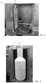
- a weight scale platform supporting tank 17 is visible in Figure 1 .
- the suspending liquid drawn with the fibre suspension in line 16 is water.
- Water drawn under vacuum through line 18 into tank 17 is substantially free of fibres since these are left behind against the walls of porous tool 15.
- suction of suspending liquid 18 through mould 15 is continuous until a predetermined volume (e.g. 10 litres) of water has been collected in tank 17.
- the "article" within tool 15 is, at this stage, a formed but wet shape held against the internal walls of the mould.
- a pressurising means is activated.
- a collapsible bladder 19 is inserted into mould 15 to act as an internal high-pressure core structure for the tool. As mentioned, this process strengthens the wet 'embryo' bottle so that it can be handled (or transported by mechanised means) before drying and displaces water in-between the cellulose fibres, thereby increasing the efficiency of the drying process.
- the bladder 19 is actuated using a hydraulic pump 20 with a cylinder that displaces a fluid in line 21 into bladder 19 to expand it and conform to the tool cavity. Fluid within line 21 is preferably non-compressible such as water. Use of water also has the advantage that any leaking or bursting of the bladder will not introduce a new substance to the system (since the suspending liquid is already water). Any bladder failures can be quickly cleaned up.
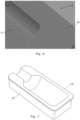
- Figures 2 and 3 show, pictorially, the appearance of a two-part mould block 14 that houses a porous mould 15 insert according to the invention. Channels through block 14 communicate with a rear side of the porous mould 15 to provide a path for suspending liquid drawn through the mould via line 18, and also reverse flow during the cleaning step (described below).
- Demoulding occurs at the step (and shown in Figure 3 ) where mould tool 15 opens for removal of a self-supporting article 22.
- a cleaning step 23 is performed to remove small fibres and maintain tool porosity/permeability.
- a high-pressure jet firing radially is inserted into the moulding chamber while the tool is open. This dislodges fibres on the surface.
- water from tank 17 is pressurised through the back of the tool 15 to dislodge entrapped fibres. Water may be drained for recycling back to an upstream step of the system. It is noteworthy that cleaning is an important step for conditioning the tool for re-use. The tool may appear visibly clean after removal of the article, but its performance will be compromised without a cleaning step.
- the self-supporting article 22 may be transported for further processing, drying etc, but such details are outside the scope of the present disclosure.
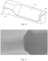
- FIG. 4 illustrates an upper portion of mould casing 14 and porous tool 15. It will be apparent that casing 14 includes a channel 24 for accommodating a seal and a fill tube 25 extends from a tool plug 26 to close off an opening into tool 15. The length of tube 25 is sufficient to extend into the substantive open volume of mould cavity 27, i.e. proximate a shoulder area of the article.
- Tube 25 overcomes issues with regard to deposition of pulp material around the neck; e.g. without this fill tube, the pulp neck may be ill-formed as it can wash away by incoming suspension. It will be apparent that tube 25 provides a hard external surface against which pulp can pack and form a neck region of the formed article. An internal surface of the bottle neck is pressed against the external surface of tube 25.
- Figure 5 shows internal detail of plug 26 and tube 25, which may include a thread for coupling to the fibre suspension delivery line 16.
- the surface structure of a tool 15, e.g. made by additive manufacturing, is illustrated by Figure 6 .
- the image shows application of a 3D printer software 'slicer' that creates holes in the tooling.
- the porous surface is comprised of a criss-cross structure resembling a relatively consistent mesh.
- the tool 15 includes a cut-away cavity 27 which provides a negative image against which the article walls take their shape. Porosity and permeability should be generally consistent across the cavity.
- the interior surface 28 of the mould tool 15 as shown, i.e. the surface in direct contact with the forming article has, according to the present embodiment, a relatively high density of pores.
- This high detail layer 28 serves as a first zone of tool 15 and, in the illustrated example, is 5mm thick around the entire outer body of the bottle.
- Figure 7 zooms out from the image of Figure 6 to show a second zone 29 that surrounds the first zone 28.
- the second zone 29 is a lower pore density support layer that prevents the structure immediately in contact with the article from breaking due to bladder inflation (19).
- the first/inner layer 28 is typically 40% - 70% porous and the second/outer layer 29 has a typical porosity of 80-90% so that suspension liquid can be quickly pumped out of the mould from the fibre deposited against cavity 27.
- the illustrated embodiment is preferred in order to achieve desirable results in the moulded article.
- the principles of providing an additive manufactured mould (insert 14) with different zones of porosity can be adapted.
- a mixture of high- and low-density areas may be in contact with the article during moulding to give different surface effects.
- Three or more zones may be found to optimise the process in some future embodiments.
- the porosity may transition from a first porosity at the cavity/inlet surface to a second porosity at the outlet surface.
- Figure 8 is a cross section view of the half-mould shown in Figure 7 .
- the high-density zone 28 is clearly seen as a layer against second zone 29 that forms the substantive volume of tool insert 15.
- Layer 28 includes a lip 30 that forms a flange at edges where two halves of tool 15 meet.
- alternative configurations are possible such as where layer 28 is contained wholly within cavity 27.
- Figure 9 shows, in greater detail, a 3D printed textured porous surface of a bottle neck.
- Tool 15 may include a neck insert associated with a closure of the moulded article.
- a neck insert associated with a closure of the moulded article.
- a ring structure may be separately formed from pulp fibre by a compression moulding process and inserted into the mould to serve as a finishing step for the mouth of a bottle 22, preferably providing a flat surface 39 onto which a heat-sealed film can be applied.
- such options are not illustrated.
- the invention can generally be considered a mould (14) for forming an article from a fibre suspension.
- the mould includes an porous insert with a cavity (27) in the negative shape of an article to be formed and two regions of different porosity (28, 29) about the cavity (27).
- the mould communicates a suspending fluid of the fibre suspension, e.g. by vacuum pump, through the at least two regions of different porosity about the cavity leaving behind a formed shape on the cavity.
Landscapes
- Engineering & Computer Science (AREA)
- Manufacturing & Machinery (AREA)
- Mechanical Engineering (AREA)
- Paper (AREA)
- Moulds For Moulding Plastics Or The Like (AREA)
- Telephone Function (AREA)
- Diaphragms For Electromechanical Transducers (AREA)
- Adornments (AREA)
- Containers Having Bodies Formed In One Piece (AREA)
- Food-Manufacturing Devices (AREA)
- Dry Formation Of Fiberboard And The Like (AREA)
- Details Of Rigid Or Semi-Rigid Containers (AREA)
- Application Of Or Painting With Fluid Materials (AREA)
- Containers And Packaging Bodies Having A Special Means To Remove Contents (AREA)
- General Preparation And Processing Of Foods (AREA)
- Casting Or Compression Moulding Of Plastics Or The Like (AREA)
- Moulding By Coating Moulds (AREA)
- Nonwoven Fabrics (AREA)
Applications Claiming Priority (4)
| Application Number | Priority Date | Filing Date | Title |
|---|---|---|---|
| GB2017432.2A GB2600700B (en) | 2020-11-04 | 2020-11-04 | A system and method for forming a moulded article |
| GB2019305.8A GB2600780B (en) | 2020-11-04 | 2020-12-08 | A mould for forming a unitary article from pulp |
| PCT/GB2021/052864 WO2022096888A1 (en) | 2020-11-04 | 2021-11-04 | A mould for forming a unitary article from pulp |
| EP21811433.8A EP4240908B1 (de) | 2020-11-04 | 2021-11-04 | Form zum herstellen eines einheitlichen artikels aus zellstoff |
Related Parent Applications (1)
| Application Number | Title | Priority Date | Filing Date |
|---|---|---|---|
| EP21811433.8A Division EP4240908B1 (de) | 2020-11-04 | 2021-11-04 | Form zum herstellen eines einheitlichen artikels aus zellstoff |
Publications (2)
| Publication Number | Publication Date |
|---|---|
| EP4497871A2 true EP4497871A2 (de) | 2025-01-29 |
| EP4497871A3 EP4497871A3 (de) | 2025-04-23 |
Family
ID=73776431
Family Applications (3)
| Application Number | Title | Priority Date | Filing Date |
|---|---|---|---|
| EP21811433.8A Active EP4240908B1 (de) | 2020-11-04 | 2021-11-04 | Form zum herstellen eines einheitlichen artikels aus zellstoff |
| EP24204680.3A Pending EP4497871A3 (de) | 2020-11-04 | 2021-11-04 | Form zum formen eines einheitlichen artikels aus zellstoff |
| EP21811119.3A Pending EP4240907A1 (de) | 2020-11-04 | 2021-11-04 | System und verfahren zur herstellung eines formartikels |
Family Applications Before (1)
| Application Number | Title | Priority Date | Filing Date |
|---|---|---|---|
| EP21811433.8A Active EP4240908B1 (de) | 2020-11-04 | 2021-11-04 | Form zum herstellen eines einheitlichen artikels aus zellstoff |
Family Applications After (1)
| Application Number | Title | Priority Date | Filing Date |
|---|---|---|---|
| EP21811119.3A Pending EP4240907A1 (de) | 2020-11-04 | 2021-11-04 | System und verfahren zur herstellung eines formartikels |
Country Status (20)
| Country | Link |
|---|---|
| US (2) | US12473695B2 (de) |
| EP (3) | EP4240908B1 (de) |
| JP (2) | JP7772063B2 (de) |
| KR (2) | KR20230112624A (de) |
| CN (2) | CN116802357A (de) |
| AU (2) | AU2021375390A1 (de) |
| CA (2) | CA3196803A1 (de) |
| CL (2) | CL2023001265A1 (de) |
| CO (2) | CO2023005667A2 (de) |
| DK (1) | DK4240908T3 (de) |
| ES (1) | ES2999544T3 (de) |
| FI (1) | FI4240908T3 (de) |
| GB (7) | GB2600700B (de) |
| HR (1) | HRP20241404T1 (de) |
| IL (2) | IL302417A (de) |
| MX (2) | MX2023004723A (de) |
| PE (2) | PE20240057A1 (de) |
| PL (1) | PL4240908T3 (de) |
| WO (2) | WO2022096888A1 (de) |
| ZA (1) | ZA202304914B (de) |
Cited By (1)
| Publication number | Priority date | Publication date | Assignee | Title |
|---|---|---|---|---|
| US20230340733A1 (en) * | 2020-11-04 | 2023-10-26 | Diageo Great Britain Limited | A Mould for Forming a Unitary Article From Pulp |
Families Citing this family (21)
| Publication number | Priority date | Publication date | Assignee | Title |
|---|---|---|---|---|
| SE543042C2 (en) * | 2019-01-03 | 2020-09-29 | Celwise Ab | Tool and method for producing a 3D molded pulp product |
| US20240218597A1 (en) * | 2019-10-14 | 2024-07-04 | Kiefel Gmbh | Mold body for a pre-pressing tool, and pre-pressing tool |
| US20240218606A1 (en) * | 2019-10-14 | 2024-07-04 | Kiefel Gmbh | Mold body with integrated connection unit for a pre-pressing tool, and pre-pressing tool |
| US20240218607A1 (en) * | 2019-10-14 | 2024-07-04 | Kiefel Gmbh | Mold body with varying thickness for a pre-pressing tool, and pre-pressing tool |
| GB2592452B (en) * | 2020-07-28 | 2023-05-24 | Frugalpac Ltd | Apparatus for manufacturing a container |
| GB2617200B (en) * | 2022-04-01 | 2024-06-12 | Pulpex Ltd | A receptacle mould and a method of manufacturing a receptacle mould |
| DE102022121491A1 (de) | 2022-08-25 | 2024-03-07 | Krones Aktiengesellschaft | Verfahren zum Herstellen eines Behälters und eine Vorrichtung zum Ausführen des Verfahrens |
| DE102022121462A1 (de) * | 2022-08-25 | 2024-03-07 | Krones Aktiengesellschaft | Verfahren zum Herstellen eines Fasern umfassenden Behälters und Vorrichtung zum Ausführen des Verfahrens |
| DE102022124327B4 (de) * | 2022-09-22 | 2025-12-18 | Kiefel Gmbh | Reinigungssystem und Reinigungsverfahren, sowie Herstellungsvorrichtung für Werkstücke |
| TW202438299A (zh) * | 2022-09-27 | 2024-10-01 | 瑞典商普勒帕克公司 | 乾式成型纖維素瓶的方法、纖維素瓶成型單元及纖維素瓶 |
| WO2024229236A2 (en) * | 2023-05-02 | 2024-11-07 | Koslow Technologies Corporation | Composition and method for making a water filter by accretion |
| GB2626623B (en) * | 2023-06-29 | 2025-08-06 | Pulpex Ltd | Mould system |
| GB2631423A (en) * | 2023-06-29 | 2025-01-08 | Pulpex Ltd | A hollow moulded fibre product transfer mechanism and associated method |
| GB2631417A (en) * | 2023-06-29 | 2025-01-08 | Pulpex Ltd | A station and method |
| GB2631419B (en) * | 2023-06-29 | 2025-08-06 | Pulpex Ltd | A station and method |
| GB2631421B (en) * | 2023-06-29 | 2025-09-03 | Pulpex Ltd | Transfer device |
| FR3158257A1 (fr) * | 2024-01-12 | 2025-07-18 | Centre Technique Industriel De La Plasturgie Et Des Composites | Moule poreux pour l’injection de fibres naturelles en suspension |
| US12146268B1 (en) * | 2024-02-02 | 2024-11-19 | PAPACKS SALES GmbH | Multipart molds and three-dimensional pulp articles molded therefrom |
| WO2025163045A1 (en) | 2024-02-02 | 2025-08-07 | PAPACKS SALES GmbH | Multipart molds and three-dimensional pulp articles molded therefrom |
| FI20245450A1 (en) * | 2024-04-10 | 2025-10-11 | Valmet Technologies Oy | Mold for producing a molded fiber product |
| GB2642330A (en) | 2024-07-03 | 2026-01-07 | Diageo Great Britain Ltd | A package |
Citations (4)
| Publication number | Priority date | Publication date | Assignee | Title |
|---|---|---|---|---|
| EP1081285A1 (de) | 1998-02-23 | 2001-03-07 | Kao Corporation | Verfahren zum fertigen von gegenständen aus papiermasse |
| EP1195466A1 (de) | 1999-01-29 | 2002-04-10 | Kao Corporation | Verfahren zur herstellung von einem faserformteil |
| EP2198088A2 (de) | 2007-09-14 | 2010-06-23 | Natural Resources (2000) Limited | Verfahren zum formen von erzeugnissen |
| WO2018020219A1 (en) | 2016-07-26 | 2018-02-01 | Natural Resources (2000) Limited | Moulding of articles |
Family Cites Families (63)
| Publication number | Priority date | Publication date | Assignee | Title |
|---|---|---|---|---|
| CA383536A (en) * | 1939-08-22 | O. Schur Milton | Moulded waterlaid fibre article manufacture | |
| GB326305A (en) * | 1928-11-24 | 1930-03-13 | Pulp Ind Ltd | Improvements in and relating to the manufacture of hollow bodies from fibrous pulp |
| US2390457A (en) * | 1942-05-07 | 1945-12-04 | Continental Can Co | Apparatus for spraying container parts |
| US2927044A (en) * | 1956-03-05 | 1960-03-01 | Minimax Ltd | Method and apparatus for spray coating the interior of hollow articles |
| US3235455A (en) * | 1962-02-09 | 1966-02-15 | Procter & Gamble | Synergistic antibacterial compositions |
| SU818663A1 (ru) * | 1979-05-11 | 1981-04-07 | Горьковский Автомобильный Завод(Производственное Объединение"Газ") | Устройство дл окраски внутрен-НЕй пОВЕРХНОСТи издЕлий |
| US4606942A (en) * | 1984-12-21 | 1986-08-19 | Adolph Coors Company | Spray coating apparatus |
| DE3735751A1 (de) * | 1987-10-22 | 1989-05-03 | Plansee Metallwerk | Heteroporoeses formwerkzeug zur herstellung von gussformen aus formsand und verfahren zu dessen herstellung |
| IT1238476B (it) * | 1990-02-06 | 1993-08-18 | Gaiotto Impianti Spa | Stampo per la colata di prodotti ceramici |
| US5232739A (en) * | 1990-10-15 | 1993-08-03 | Ball Corporation | Dual orifice nozzle and method for internally coating containers |
| JP2836801B2 (ja) * | 1992-03-06 | 1998-12-14 | 日本碍子株式会社 | 繊維成形物の抄造型、抄造方法及び抄造装置、並びに抄造された繊維成形物 |
| ES2132717T3 (es) * | 1994-11-02 | 1999-08-16 | Portec Ag | Dispositivo de circulacion de un fluido entre un volumen delimitado por una superficie solida y un canal, y procedimiento de fabricacion de este dispositivo. |
| JPH10212700A (ja) * | 1997-01-21 | 1998-08-11 | Kobayashi Seisakusho:Kk | パルプモールド抄造方法及び装置 |
| JPH11342550A (ja) * | 1998-05-29 | 1999-12-14 | Kao Corp | パルプモールド成形品の抄紙型 |
| DE69942248D1 (de) | 1998-02-23 | 2010-05-27 | Kao Corp | Verfahren zur herstellung eines formkörpers aus faserstoff |
| JP3122408B2 (ja) * | 1998-02-23 | 2001-01-09 | 花王株式会社 | パルプモールド成形品の製造方法 |
| WO1999042659A1 (en) | 1998-02-23 | 1999-08-26 | Kao Corporation | Method of manufacturing pulp molded product |
| JP2000027099A (ja) * | 1998-07-03 | 2000-01-25 | Oji Paper Co Ltd | 凹凸成形体の製造方法 |
| JP2001055697A (ja) * | 1999-08-06 | 2001-02-27 | Kao Corp | パルプモールド成形体の製造方法 |
| US7048975B1 (en) * | 1999-10-15 | 2006-05-23 | Kao Corporation | Pulp molded container |
| JP3960723B2 (ja) * | 1999-11-10 | 2007-08-15 | 花王株式会社 | パルプモールド成形体の製造方法 |
| JP2001140200A (ja) * | 1999-11-12 | 2001-05-22 | Kao Corp | パルプモールド成形体の製造方法 |
| JP2001137752A (ja) * | 1999-11-16 | 2001-05-22 | Tokyo Gas Co Ltd | 既設管路の更生修理工法 |
| EP1104822B1 (de) * | 1999-11-17 | 2007-02-14 | Kao Corporation | Verfahren zur Herstellung von faserigen Formteilen |
| JP3331211B2 (ja) * | 2000-03-01 | 2002-10-07 | 花王株式会社 | パルプモールド成形体 |
| WO2001068984A1 (fr) * | 2000-03-13 | 2001-09-20 | Kao Corporation | Moule de sechage pour corps moule a partir de pate |
| US6918997B2 (en) * | 2000-04-18 | 2005-07-19 | Kao Corporation | Method of producing pulp moldings |
| JP2002105899A (ja) * | 2000-09-29 | 2002-04-10 | Kao Corp | 抄造容器 |
| JP3415607B2 (ja) * | 2001-07-24 | 2003-06-09 | 花王株式会社 | 繊維成形体の製造方法 |
| KR20020028926A (ko) | 2002-01-10 | 2002-04-17 | 김휘주 | 펄프몰드 성형용기의 제조방법 |
| GB2416143A (en) * | 2004-07-15 | 2006-01-18 | Glory Team Ind Ltd | An apparatus and a method of producing pulp moulded products |
| DE102005038887A1 (de) * | 2005-08-17 | 2007-03-01 | Dorst Technologies Gmbh & Co. Kg | Gussform für ein Niederdruck-Gussverfahren, Verfahren zum Herstellen einer solchen Gussform und Verfahren zum Niederdruckgießen |
| SE529164C2 (sv) * | 2004-11-26 | 2007-05-22 | Pakit Int Trading Co Inc | Massaform och användning av massaform |
| SE528685C2 (sv) * | 2004-11-26 | 2007-01-23 | Pakit Int Trading Co Inc | Metod och maskin för att tillverka fiberprodukter av mäld |
| JP2007292304A (ja) * | 2006-03-27 | 2007-11-08 | Kurimoto Ltd | パイプ類の端面閉鎖キャップ |
| DE102008008968A1 (de) | 2008-02-13 | 2009-08-20 | Schlickenrieder, Klaus, Dr. Ing. | Form zum Herstellen von flüssigkeitshaltigen Teilen |
| CN103314156A (zh) | 2010-06-15 | 2013-09-18 | Pakit国际贸易股份有限公司 | 在模制纤维产品上应用薄膜的方法以及通过所述方法制造的产品 |
| FR2965491B1 (fr) * | 2010-10-05 | 2013-05-17 | Sgd Sa | Procede de revetement et machine de revetement correspondante |
| CN103874636B (zh) * | 2011-07-19 | 2016-04-13 | 李盖博有限责任公司 | 可生物降解的液体瓶 |
| EP3038936B1 (de) * | 2013-10-02 | 2024-08-07 | Eco.logic Brands Inc. | Behälter für partikelförmige materialien |
| CN106170347B (zh) * | 2014-04-21 | 2018-11-13 | 东洋制罐株式会社 | 涂布装置 |
| ES2772850T3 (es) * | 2014-05-07 | 2020-07-08 | Univ Maine System | Producción de alta eficiencia de celulosa nanofibrilada |
| PL3204556T3 (pl) | 2014-10-08 | 2019-05-31 | Ecoxpac As | Układ i sposób wytwarzania formowanego wyrobu, takiego jak butelka |
| US9932710B2 (en) * | 2014-12-12 | 2018-04-03 | Golden Arrow Printing Co., Ltd. | Porous metal mold for wet pulp molding process and method of using the same |
| BR112017013298B1 (pt) * | 2014-12-22 | 2021-12-21 | Celwise Ab | Ferramenta ou parte de ferramenta, método e sistema para moldar um produto |
| HUE036967T2 (hu) * | 2015-01-20 | 2018-08-28 | Sturm Maschinen & Anlagenbau Gmbh | Eljárás és bevonó berendezés üregek falainak bevonására |
| TWI610007B (zh) * | 2016-09-23 | 2018-01-01 | 紙塑蓋體及其成形裝置 | |
| DE102017214469A1 (de) * | 2017-08-18 | 2019-02-21 | Sig Technology Ag | Ein Verfahren zum Herstellen eines Behälters aus einem Behälterrohling, insbesondere mit einem Verringern einer Höhe des Behälterrohlings |
| SE543041C2 (en) * | 2018-07-19 | 2020-09-29 | Celwise Ab | Method of producing a pulp product |
| SE543042C2 (en) * | 2019-01-03 | 2020-09-29 | Celwise Ab | Tool and method for producing a 3D molded pulp product |
| EP3708709A1 (de) | 2019-03-14 | 2020-09-16 | Danmarks Tekniske Universitet | Verfahren zur herstellung eines geformten zellstoffprodukts und zellstoffformvorrichtung |
| WO2021016664A1 (en) * | 2019-07-30 | 2021-02-04 | Varden Process Pty Ltd | A moulded pulp fibre product, and method of forming same |
| CN210916808U (zh) * | 2019-09-25 | 2020-07-03 | 龙口市科利马工贸有限公司 | 一种用于瓶状制品纸浆模塑的模具和设备 |
| WO2021142505A1 (en) * | 2020-01-18 | 2021-07-22 | LIAO, Yun-Hsuan | Paper pulp cup lids with double lock structure and its forming method |
| EP3985170A1 (de) | 2020-10-19 | 2022-04-20 | Valmet Technologies Oy | Form zur herstellung eines faserformproduktes |
| GB2600700B (en) * | 2020-11-04 | 2023-07-12 | Diageo Great Britain Ltd | A system and method for forming a moulded article |
| CN112411264B (zh) | 2020-11-24 | 2023-01-13 | 天津茂创科技发展有限公司 | 一种模制纤维中空结构制品的定型装置及其制备方法 |
| SE2230069A1 (en) * | 2022-03-11 | 2023-09-12 | Stora Enso Oyj | A tool for molding a fiber-based product |
| GB2616479B (en) * | 2022-03-11 | 2024-10-16 | Pulpex Ltd | Method of and system for forming a receptacle |
| GB2617200B (en) * | 2022-04-01 | 2024-06-12 | Pulpex Ltd | A receptacle mould and a method of manufacturing a receptacle mould |
| US20240200274A1 (en) * | 2022-12-06 | 2024-06-20 | The Procter & Gamble Company | Multi-Region Pulp Article |
| WO2024144980A2 (en) * | 2022-12-06 | 2024-07-04 | The Procter & Gamble Company | Multi-region pulp article |
| GB2628131A (en) * | 2023-03-14 | 2024-09-18 | Pulpex Ltd | Moulding of hollow moulded fibre products |
-
2020
- 2020-11-04 GB GB2017432.2A patent/GB2600700B/en active Active
- 2020-12-08 GB GBGB2019307.4A patent/GB202019307D0/en not_active Ceased
- 2020-12-08 GB GB2210014.3A patent/GB2611848A/en not_active Withdrawn
- 2020-12-08 GB GB2019308.2A patent/GB2600781B/en active Active
- 2020-12-08 GB GB2019305.8A patent/GB2600780B/en active Active
- 2020-12-08 GB GB2210013.5A patent/GB2614773A/en not_active Withdrawn
- 2020-12-08 GB GB2112650.3A patent/GB2600809B/en active Active
-
2021
- 2021-11-04 EP EP21811433.8A patent/EP4240908B1/de active Active
- 2021-11-04 CA CA3196803A patent/CA3196803A1/en active Pending
- 2021-11-04 CN CN202180081349.0A patent/CN116802357A/zh active Pending
- 2021-11-04 DK DK21811433.8T patent/DK4240908T3/da active
- 2021-11-04 EP EP24204680.3A patent/EP4497871A3/de active Pending
- 2021-11-04 IL IL302417A patent/IL302417A/en unknown
- 2021-11-04 ES ES21811433T patent/ES2999544T3/es active Active
- 2021-11-04 EP EP21811119.3A patent/EP4240907A1/de active Pending
- 2021-11-04 US US18/033,406 patent/US12473695B2/en active Active
- 2021-11-04 JP JP2023524760A patent/JP7772063B2/ja active Active
- 2021-11-04 FI FIEP21811433.8T patent/FI4240908T3/fi active
- 2021-11-04 PE PE2023001545A patent/PE20240057A1/es unknown
- 2021-11-04 JP JP2023524979A patent/JP2024503777A/ja active Pending
- 2021-11-04 KR KR1020237017005A patent/KR20230112624A/ko active Pending
- 2021-11-04 PL PL21811433.8T patent/PL4240908T3/pl unknown
- 2021-11-04 HR HRP20241404TT patent/HRP20241404T1/hr unknown
- 2021-11-04 CN CN202180081911.XA patent/CN116583644A/zh active Pending
- 2021-11-04 PE PE2023001544A patent/PE20231807A1/es unknown
- 2021-11-04 AU AU2021375390A patent/AU2021375390A1/en active Pending
- 2021-11-04 US US18/033,238 patent/US20230340733A1/en active Pending
- 2021-11-04 KR KR1020237016919A patent/KR20230112623A/ko active Pending
- 2021-11-04 WO PCT/GB2021/052864 patent/WO2022096888A1/en not_active Ceased
- 2021-11-04 MX MX2023004723A patent/MX2023004723A/es unknown
- 2021-11-04 AU AU2021374875A patent/AU2021374875A1/en active Pending
- 2021-11-04 CA CA3196795A patent/CA3196795A1/en active Pending
- 2021-11-04 MX MX2023004753A patent/MX2023004753A/es unknown
- 2021-11-04 IL IL302418A patent/IL302418A/en unknown
- 2021-11-04 WO PCT/GB2021/052863 patent/WO2022096887A1/en not_active Ceased
-
2023
- 2023-05-02 CL CL2023001265A patent/CL2023001265A1/es unknown
- 2023-05-02 CL CL2023001264A patent/CL2023001264A1/es unknown
- 2023-05-02 ZA ZA2023/04914A patent/ZA202304914B/en unknown
- 2023-05-03 CO CONC2023/0005667A patent/CO2023005667A2/es unknown
- 2023-05-03 CO CONC2023/0005676A patent/CO2023005676A2/es unknown
Patent Citations (4)
| Publication number | Priority date | Publication date | Assignee | Title |
|---|---|---|---|---|
| EP1081285A1 (de) | 1998-02-23 | 2001-03-07 | Kao Corporation | Verfahren zum fertigen von gegenständen aus papiermasse |
| EP1195466A1 (de) | 1999-01-29 | 2002-04-10 | Kao Corporation | Verfahren zur herstellung von einem faserformteil |
| EP2198088A2 (de) | 2007-09-14 | 2010-06-23 | Natural Resources (2000) Limited | Verfahren zum formen von erzeugnissen |
| WO2018020219A1 (en) | 2016-07-26 | 2018-02-01 | Natural Resources (2000) Limited | Moulding of articles |
Cited By (1)
| Publication number | Priority date | Publication date | Assignee | Title |
|---|---|---|---|---|
| US20230340733A1 (en) * | 2020-11-04 | 2023-10-26 | Diageo Great Britain Limited | A Mould for Forming a Unitary Article From Pulp |
Also Published As
Similar Documents
| Publication | Publication Date | Title |
|---|---|---|
| EP4240908B1 (de) | Form zum herstellen eines einheitlichen artikels aus zellstoff | |
| AU2023232472B2 (en) | Method of and system for forming a receptacle | |
| US20250012016A1 (en) | Receptacle mould and a method of manufacturing a receptacle mould | |
| HK40074907A (en) | A mould for forming a unitary article from pulp | |
| AU2024237502A1 (en) | Moulding of hollow moulded fibre products | |
| HK40074094A (en) | A system and method for forming a moulded article | |
| US20260015801A1 (en) | Moulding of hollow moulded fibre products | |
| US20250137204A1 (en) | Method and system for forming a receptacle | |
| WO2024069163A1 (en) | System for and method of forming a receptacle | |
| EP4680535A1 (de) | Formen von geformten hohlfaserprodukten |
Legal Events
| Date | Code | Title | Description |
|---|---|---|---|
| PUAI | Public reference made under article 153(3) epc to a published international application that has entered the european phase |
Free format text: ORIGINAL CODE: 0009012 |
|
| STAA | Information on the status of an ep patent application or granted ep patent |
Free format text: STATUS: THE APPLICATION HAS BEEN PUBLISHED |
|
| AC | Divisional application: reference to earlier application |
Ref document number: 4240908 Country of ref document: EP Kind code of ref document: P |
|
| AK | Designated contracting states |
Kind code of ref document: A2 Designated state(s): AL AT BE BG CH CY CZ DE DK EE ES FI FR GB GR HR HU IE IS IT LI LT LU LV MC MK MT NL NO PL PT RO RS SE SI SK SM TR |
|
| REG | Reference to a national code |
Ref country code: DE Ref legal event code: R079 Free format text: PREVIOUS MAIN CLASS: D21J0003100000 Ipc: D21J0007000000 |
|
| PUAL | Search report despatched |
Free format text: ORIGINAL CODE: 0009013 |
|
| AK | Designated contracting states |
Kind code of ref document: A3 Designated state(s): AL AT BE BG CH CY CZ DE DK EE ES FI FR GB GR HR HU IE IS IT LI LT LU LV MC MK MT NL NO PL PT RO RS SE SI SK SM TR |
|
| RIC1 | Information provided on ipc code assigned before grant |
Ipc: D21J 3/10 20060101ALI20250319BHEP Ipc: D21J 7/00 20060101AFI20250319BHEP |
|
| STAA | Information on the status of an ep patent application or granted ep patent |
Free format text: STATUS: REQUEST FOR EXAMINATION WAS MADE |
|
| 17P | Request for examination filed |
Effective date: 20251022 |