EP4497579A1 - Integrierte geformte komponente und verfahren zur herstellung einer integrierten geformten komponente - Google Patents
Integrierte geformte komponente und verfahren zur herstellung einer integrierten geformten komponente Download PDFInfo
- Publication number
- EP4497579A1 EP4497579A1 EP23774754.8A EP23774754A EP4497579A1 EP 4497579 A1 EP4497579 A1 EP 4497579A1 EP 23774754 A EP23774754 A EP 23774754A EP 4497579 A1 EP4497579 A1 EP 4497579A1
- Authority
- EP
- European Patent Office
- Prior art keywords
- structural member
- resin
- molded component
- integrated molded
- thermoplastic resin
- Prior art date
- Legal status (The legal status is an assumption and is not a legal conclusion. Google has not performed a legal analysis and makes no representation as to the accuracy of the status listed.)
- Pending
Links
Images


Classifications
-
- B—PERFORMING OPERATIONS; TRANSPORTING
- B29—WORKING OF PLASTICS; WORKING OF SUBSTANCES IN A PLASTIC STATE IN GENERAL
- B29C—SHAPING OR JOINING OF PLASTICS; SHAPING OF MATERIAL IN A PLASTIC STATE, NOT OTHERWISE PROVIDED FOR; AFTER-TREATMENT OF THE SHAPED PRODUCTS, e.g. REPAIRING
- B29C65/00—Joining or sealing of preformed parts, e.g. welding of plastics materials; Apparatus therefor
- B29C65/70—Joining or sealing of preformed parts, e.g. welding of plastics materials; Apparatus therefor by moulding
-
- B—PERFORMING OPERATIONS; TRANSPORTING
- B29—WORKING OF PLASTICS; WORKING OF SUBSTANCES IN A PLASTIC STATE IN GENERAL
- B29C—SHAPING OR JOINING OF PLASTICS; SHAPING OF MATERIAL IN A PLASTIC STATE, NOT OTHERWISE PROVIDED FOR; AFTER-TREATMENT OF THE SHAPED PRODUCTS, e.g. REPAIRING
- B29C66/00—General aspects of processes or apparatus for joining preformed parts
- B29C66/70—General aspects of processes or apparatus for joining preformed parts characterised by the composition, physical properties or the structure of the material of the parts to be joined; Joining with non-plastics material
- B29C66/72—General aspects of processes or apparatus for joining preformed parts characterised by the composition, physical properties or the structure of the material of the parts to be joined; Joining with non-plastics material characterised by the structure of the material of the parts to be joined
- B29C66/721—Fibre-reinforced materials
-
- B—PERFORMING OPERATIONS; TRANSPORTING
- B29—WORKING OF PLASTICS; WORKING OF SUBSTANCES IN A PLASTIC STATE IN GENERAL
- B29C—SHAPING OR JOINING OF PLASTICS; SHAPING OF MATERIAL IN A PLASTIC STATE, NOT OTHERWISE PROVIDED FOR; AFTER-TREATMENT OF THE SHAPED PRODUCTS, e.g. REPAIRING
- B29C45/00—Injection moulding, i.e. forcing the required volume of moulding material through a nozzle into a closed mould; Apparatus therefor
- B29C45/14—Injection moulding, i.e. forcing the required volume of moulding material through a nozzle into a closed mould; Apparatus therefor incorporating preformed parts or layers, e.g. injection moulding around inserts or for coating articles
- B29C45/14467—Joining articles or parts of a single article
- B29C45/14491—Injecting material between coaxial articles, e.g. between a core and an outside sleeve for making a roll
-
- B—PERFORMING OPERATIONS; TRANSPORTING
- B29—WORKING OF PLASTICS; WORKING OF SUBSTANCES IN A PLASTIC STATE IN GENERAL
- B29C—SHAPING OR JOINING OF PLASTICS; SHAPING OF MATERIAL IN A PLASTIC STATE, NOT OTHERWISE PROVIDED FOR; AFTER-TREATMENT OF THE SHAPED PRODUCTS, e.g. REPAIRING
- B29C45/00—Injection moulding, i.e. forcing the required volume of moulding material through a nozzle into a closed mould; Apparatus therefor
- B29C45/16—Making multilayered or multicoloured articles
- B29C45/1642—Making multilayered or multicoloured articles having a "sandwich" structure
-
- B—PERFORMING OPERATIONS; TRANSPORTING
- B29—WORKING OF PLASTICS; WORKING OF SUBSTANCES IN A PLASTIC STATE IN GENERAL
- B29C—SHAPING OR JOINING OF PLASTICS; SHAPING OF MATERIAL IN A PLASTIC STATE, NOT OTHERWISE PROVIDED FOR; AFTER-TREATMENT OF THE SHAPED PRODUCTS, e.g. REPAIRING
- B29C45/00—Injection moulding, i.e. forcing the required volume of moulding material through a nozzle into a closed mould; Apparatus therefor
- B29C45/16—Making multilayered or multicoloured articles
- B29C45/1671—Making multilayered or multicoloured articles with an insert
-
- B—PERFORMING OPERATIONS; TRANSPORTING
- B29—WORKING OF PLASTICS; WORKING OF SUBSTANCES IN A PLASTIC STATE IN GENERAL
- B29C—SHAPING OR JOINING OF PLASTICS; SHAPING OF MATERIAL IN A PLASTIC STATE, NOT OTHERWISE PROVIDED FOR; AFTER-TREATMENT OF THE SHAPED PRODUCTS, e.g. REPAIRING
- B29C65/00—Joining or sealing of preformed parts, e.g. welding of plastics materials; Apparatus therefor
- B29C65/02—Joining or sealing of preformed parts, e.g. welding of plastics materials; Apparatus therefor by heating, with or without pressure
- B29C65/40—Applying molten plastics, e.g. hot melt
-
- B—PERFORMING OPERATIONS; TRANSPORTING
- B29—WORKING OF PLASTICS; WORKING OF SUBSTANCES IN A PLASTIC STATE IN GENERAL
- B29C—SHAPING OR JOINING OF PLASTICS; SHAPING OF MATERIAL IN A PLASTIC STATE, NOT OTHERWISE PROVIDED FOR; AFTER-TREATMENT OF THE SHAPED PRODUCTS, e.g. REPAIRING
- B29C65/00—Joining or sealing of preformed parts, e.g. welding of plastics materials; Apparatus therefor
- B29C65/48—Joining or sealing of preformed parts, e.g. welding of plastics materials; Apparatus therefor using adhesives, i.e. using supplementary joining material; solvent bonding
- B29C65/4805—Joining or sealing of preformed parts, e.g. welding of plastics materials; Apparatus therefor using adhesives, i.e. using supplementary joining material; solvent bonding characterised by the type of adhesives
- B29C65/481—Non-reactive adhesives, e.g. physically hardening adhesives
- B29C65/4815—Hot melt adhesives, e.g. thermoplastic adhesives
-
- B—PERFORMING OPERATIONS; TRANSPORTING
- B29—WORKING OF PLASTICS; WORKING OF SUBSTANCES IN A PLASTIC STATE IN GENERAL
- B29C—SHAPING OR JOINING OF PLASTICS; SHAPING OF MATERIAL IN A PLASTIC STATE, NOT OTHERWISE PROVIDED FOR; AFTER-TREATMENT OF THE SHAPED PRODUCTS, e.g. REPAIRING
- B29C65/00—Joining or sealing of preformed parts, e.g. welding of plastics materials; Apparatus therefor
- B29C65/48—Joining or sealing of preformed parts, e.g. welding of plastics materials; Apparatus therefor using adhesives, i.e. using supplementary joining material; solvent bonding
- B29C65/50—Joining or sealing of preformed parts, e.g. welding of plastics materials; Apparatus therefor using adhesives, i.e. using supplementary joining material; solvent bonding using adhesive tape, e.g. thermoplastic tape; using threads or the like
- B29C65/5057—Joining or sealing of preformed parts, e.g. welding of plastics materials; Apparatus therefor using adhesives, i.e. using supplementary joining material; solvent bonding using adhesive tape, e.g. thermoplastic tape; using threads or the like positioned between the surfaces to be joined
-
- B—PERFORMING OPERATIONS; TRANSPORTING
- B29—WORKING OF PLASTICS; WORKING OF SUBSTANCES IN A PLASTIC STATE IN GENERAL
- B29C—SHAPING OR JOINING OF PLASTICS; SHAPING OF MATERIAL IN A PLASTIC STATE, NOT OTHERWISE PROVIDED FOR; AFTER-TREATMENT OF THE SHAPED PRODUCTS, e.g. REPAIRING
- B29C66/00—General aspects of processes or apparatus for joining preformed parts
- B29C66/01—General aspects dealing with the joint area or with the area to be joined
- B29C66/05—Particular design of joint configurations
- B29C66/10—Particular design of joint configurations particular design of the joint cross-sections
- B29C66/11—Joint cross-sections comprising a single joint-segment, i.e. one of the parts to be joined comprising a single joint-segment in the joint cross-section
- B29C66/112—Single lapped joints
- B29C66/1122—Single lap to lap joints, i.e. overlap joints
-
- B—PERFORMING OPERATIONS; TRANSPORTING
- B29—WORKING OF PLASTICS; WORKING OF SUBSTANCES IN A PLASTIC STATE IN GENERAL
- B29C—SHAPING OR JOINING OF PLASTICS; SHAPING OF MATERIAL IN A PLASTIC STATE, NOT OTHERWISE PROVIDED FOR; AFTER-TREATMENT OF THE SHAPED PRODUCTS, e.g. REPAIRING
- B29C66/00—General aspects of processes or apparatus for joining preformed parts
- B29C66/50—General aspects of joining tubular articles; General aspects of joining long products, i.e. bars or profiled elements; General aspects of joining single elements to tubular articles, hollow articles or bars; General aspects of joining several hollow-preforms to form hollow or tubular articles
- B29C66/51—Joining tubular articles, profiled elements or bars; Joining single elements to tubular articles, hollow articles or bars; Joining several hollow-preforms to form hollow or tubular articles
- B29C66/52—Joining tubular articles, bars or profiled elements
- B29C66/522—Joining tubular articles
- B29C66/5221—Joining tubular articles for forming coaxial connections, i.e. the tubular articles to be joined forming a zero angle relative to each other
-
- B—PERFORMING OPERATIONS; TRANSPORTING
- B29—WORKING OF PLASTICS; WORKING OF SUBSTANCES IN A PLASTIC STATE IN GENERAL
- B29C—SHAPING OR JOINING OF PLASTICS; SHAPING OF MATERIAL IN A PLASTIC STATE, NOT OTHERWISE PROVIDED FOR; AFTER-TREATMENT OF THE SHAPED PRODUCTS, e.g. REPAIRING
- B29C66/00—General aspects of processes or apparatus for joining preformed parts
- B29C66/50—General aspects of joining tubular articles; General aspects of joining long products, i.e. bars or profiled elements; General aspects of joining single elements to tubular articles, hollow articles or bars; General aspects of joining several hollow-preforms to form hollow or tubular articles
- B29C66/51—Joining tubular articles, profiled elements or bars; Joining single elements to tubular articles, hollow articles or bars; Joining several hollow-preforms to form hollow or tubular articles
- B29C66/53—Joining single elements to tubular articles, hollow articles or bars
- B29C66/532—Joining single elements to the wall of tubular articles, hollow articles or bars
-
- B—PERFORMING OPERATIONS; TRANSPORTING
- B29—WORKING OF PLASTICS; WORKING OF SUBSTANCES IN A PLASTIC STATE IN GENERAL
- B29C—SHAPING OR JOINING OF PLASTICS; SHAPING OF MATERIAL IN A PLASTIC STATE, NOT OTHERWISE PROVIDED FOR; AFTER-TREATMENT OF THE SHAPED PRODUCTS, e.g. REPAIRING
- B29C66/00—General aspects of processes or apparatus for joining preformed parts
- B29C66/50—General aspects of joining tubular articles; General aspects of joining long products, i.e. bars or profiled elements; General aspects of joining single elements to tubular articles, hollow articles or bars; General aspects of joining several hollow-preforms to form hollow or tubular articles
- B29C66/51—Joining tubular articles, profiled elements or bars; Joining single elements to tubular articles, hollow articles or bars; Joining several hollow-preforms to form hollow or tubular articles
- B29C66/53—Joining single elements to tubular articles, hollow articles or bars
- B29C66/534—Joining single elements to open ends of tubular or hollow articles or to the ends of bars
- B29C66/5344—Joining single elements to open ends of tubular or hollow articles or to the ends of bars said single elements being substantially annular, i.e. of finite length, e.g. joining flanges to tube ends
-
- B—PERFORMING OPERATIONS; TRANSPORTING
- B29—WORKING OF PLASTICS; WORKING OF SUBSTANCES IN A PLASTIC STATE IN GENERAL
- B29C—SHAPING OR JOINING OF PLASTICS; SHAPING OF MATERIAL IN A PLASTIC STATE, NOT OTHERWISE PROVIDED FOR; AFTER-TREATMENT OF THE SHAPED PRODUCTS, e.g. REPAIRING
- B29C66/00—General aspects of processes or apparatus for joining preformed parts
- B29C66/50—General aspects of joining tubular articles; General aspects of joining long products, i.e. bars or profiled elements; General aspects of joining single elements to tubular articles, hollow articles or bars; General aspects of joining several hollow-preforms to form hollow or tubular articles
- B29C66/61—Joining from or joining on the inside
-
- B—PERFORMING OPERATIONS; TRANSPORTING
- B29—WORKING OF PLASTICS; WORKING OF SUBSTANCES IN A PLASTIC STATE IN GENERAL
- B29C—SHAPING OR JOINING OF PLASTICS; SHAPING OF MATERIAL IN A PLASTIC STATE, NOT OTHERWISE PROVIDED FOR; AFTER-TREATMENT OF THE SHAPED PRODUCTS, e.g. REPAIRING
- B29C66/00—General aspects of processes or apparatus for joining preformed parts
- B29C66/70—General aspects of processes or apparatus for joining preformed parts characterised by the composition, physical properties or the structure of the material of the parts to be joined; Joining with non-plastics material
- B29C66/73—General aspects of processes or apparatus for joining preformed parts characterised by the composition, physical properties or the structure of the material of the parts to be joined; Joining with non-plastics material characterised by the intensive physical properties of the material of the parts to be joined, by the optical properties of the material of the parts to be joined, by the extensive physical properties of the parts to be joined, by the state of the material of the parts to be joined or by the material of the parts to be joined being a thermoplastic or a thermoset
- B29C66/739—General aspects of processes or apparatus for joining preformed parts characterised by the composition, physical properties or the structure of the material of the parts to be joined; Joining with non-plastics material characterised by the intensive physical properties of the material of the parts to be joined, by the optical properties of the material of the parts to be joined, by the extensive physical properties of the parts to be joined, by the state of the material of the parts to be joined or by the material of the parts to be joined being a thermoplastic or a thermoset characterised by the material of the parts to be joined being a thermoplastic or a thermoset
- B29C66/7394—General aspects of processes or apparatus for joining preformed parts characterised by the composition, physical properties or the structure of the material of the parts to be joined; Joining with non-plastics material characterised by the intensive physical properties of the material of the parts to be joined, by the optical properties of the material of the parts to be joined, by the extensive physical properties of the parts to be joined, by the state of the material of the parts to be joined or by the material of the parts to be joined being a thermoplastic or a thermoset characterised by the material of the parts to be joined being a thermoplastic or a thermoset characterised by the material of at least one of the parts being a thermoset
- B29C66/73941—General aspects of processes or apparatus for joining preformed parts characterised by the composition, physical properties or the structure of the material of the parts to be joined; Joining with non-plastics material characterised by the intensive physical properties of the material of the parts to be joined, by the optical properties of the material of the parts to be joined, by the extensive physical properties of the parts to be joined, by the state of the material of the parts to be joined or by the material of the parts to be joined being a thermoplastic or a thermoset characterised by the material of the parts to be joined being a thermoplastic or a thermoset characterised by the material of at least one of the parts being a thermoset characterised by the materials of both parts being thermosets
-
- B—PERFORMING OPERATIONS; TRANSPORTING
- B29—WORKING OF PLASTICS; WORKING OF SUBSTANCES IN A PLASTIC STATE IN GENERAL
- B29C—SHAPING OR JOINING OF PLASTICS; SHAPING OF MATERIAL IN A PLASTIC STATE, NOT OTHERWISE PROVIDED FOR; AFTER-TREATMENT OF THE SHAPED PRODUCTS, e.g. REPAIRING
- B29C70/00—Shaping composites, i.e. plastics material comprising reinforcements, fillers or preformed parts, e.g. inserts
- B29C70/68—Shaping composites, i.e. plastics material comprising reinforcements, fillers or preformed parts, e.g. inserts by incorporating or moulding on preformed parts, e.g. inserts or layers, e.g. foam blocks
- B29C70/681—Component parts, details or accessories; Auxiliary operations
- B29C70/682—Preformed parts characterised by their structure, e.g. form
-
- B—PERFORMING OPERATIONS; TRANSPORTING
- B29—WORKING OF PLASTICS; WORKING OF SUBSTANCES IN A PLASTIC STATE IN GENERAL
- B29C—SHAPING OR JOINING OF PLASTICS; SHAPING OF MATERIAL IN A PLASTIC STATE, NOT OTHERWISE PROVIDED FOR; AFTER-TREATMENT OF THE SHAPED PRODUCTS, e.g. REPAIRING
- B29C70/00—Shaping composites, i.e. plastics material comprising reinforcements, fillers or preformed parts, e.g. inserts
- B29C70/68—Shaping composites, i.e. plastics material comprising reinforcements, fillers or preformed parts, e.g. inserts by incorporating or moulding on preformed parts, e.g. inserts or layers, e.g. foam blocks
- B29C70/72—Encapsulating inserts having non-encapsulated projections, e.g. extremities or terminal portions of electrical components
-
- B—PERFORMING OPERATIONS; TRANSPORTING
- B29—WORKING OF PLASTICS; WORKING OF SUBSTANCES IN A PLASTIC STATE IN GENERAL
- B29C—SHAPING OR JOINING OF PLASTICS; SHAPING OF MATERIAL IN A PLASTIC STATE, NOT OTHERWISE PROVIDED FOR; AFTER-TREATMENT OF THE SHAPED PRODUCTS, e.g. REPAIRING
- B29C70/00—Shaping composites, i.e. plastics material comprising reinforcements, fillers or preformed parts, e.g. inserts
- B29C70/68—Shaping composites, i.e. plastics material comprising reinforcements, fillers or preformed parts, e.g. inserts by incorporating or moulding on preformed parts, e.g. inserts or layers, e.g. foam blocks
- B29C70/74—Moulding material on a relatively small portion of the preformed part, e.g. outsert moulding
- B29C70/747—Applying material, e.g. foam, only in a limited number of places or in a pattern, e.g. to create a decorative effect
-
- B—PERFORMING OPERATIONS; TRANSPORTING
- B29—WORKING OF PLASTICS; WORKING OF SUBSTANCES IN A PLASTIC STATE IN GENERAL
- B29C—SHAPING OR JOINING OF PLASTICS; SHAPING OF MATERIAL IN A PLASTIC STATE, NOT OTHERWISE PROVIDED FOR; AFTER-TREATMENT OF THE SHAPED PRODUCTS, e.g. REPAIRING
- B29C70/00—Shaping composites, i.e. plastics material comprising reinforcements, fillers or preformed parts, e.g. inserts
- B29C70/68—Shaping composites, i.e. plastics material comprising reinforcements, fillers or preformed parts, e.g. inserts by incorporating or moulding on preformed parts, e.g. inserts or layers, e.g. foam blocks
- B29C70/74—Moulding material on a relatively small portion of the preformed part, e.g. outsert moulding
- B29C70/76—Moulding on edges or extremities of the preformed part
- B29C70/766—Moulding on edges or extremities of the preformed part on the end part of a tubular article
-
- B—PERFORMING OPERATIONS; TRANSPORTING
- B29—WORKING OF PLASTICS; WORKING OF SUBSTANCES IN A PLASTIC STATE IN GENERAL
- B29C—SHAPING OR JOINING OF PLASTICS; SHAPING OF MATERIAL IN A PLASTIC STATE, NOT OTHERWISE PROVIDED FOR; AFTER-TREATMENT OF THE SHAPED PRODUCTS, e.g. REPAIRING
- B29C65/00—Joining or sealing of preformed parts, e.g. welding of plastics materials; Apparatus therefor
- B29C65/02—Joining or sealing of preformed parts, e.g. welding of plastics materials; Apparatus therefor by heating, with or without pressure
- B29C65/14—Joining or sealing of preformed parts, e.g. welding of plastics materials; Apparatus therefor by heating, with or without pressure using wave energy, i.e. electromagnetic radiation, or particle radiation
- B29C65/1403—Joining or sealing of preformed parts, e.g. welding of plastics materials; Apparatus therefor by heating, with or without pressure using wave energy, i.e. electromagnetic radiation, or particle radiation characterised by the type of electromagnetic or particle radiation
- B29C65/1412—Infrared [IR] radiation
- B29C65/1422—Far-infrared radiation [FIR]
-
- B—PERFORMING OPERATIONS; TRANSPORTING
- B29—WORKING OF PLASTICS; WORKING OF SUBSTANCES IN A PLASTIC STATE IN GENERAL
- B29C—SHAPING OR JOINING OF PLASTICS; SHAPING OF MATERIAL IN A PLASTIC STATE, NOT OTHERWISE PROVIDED FOR; AFTER-TREATMENT OF THE SHAPED PRODUCTS, e.g. REPAIRING
- B29C66/00—General aspects of processes or apparatus for joining preformed parts
- B29C66/70—General aspects of processes or apparatus for joining preformed parts characterised by the composition, physical properties or the structure of the material of the parts to be joined; Joining with non-plastics material
- B29C66/72—General aspects of processes or apparatus for joining preformed parts characterised by the composition, physical properties or the structure of the material of the parts to be joined; Joining with non-plastics material characterised by the structure of the material of the parts to be joined
- B29C66/721—Fibre-reinforced materials
- B29C66/7214—Fibre-reinforced materials characterised by the length of the fibres
- B29C66/72141—Fibres of continuous length
-
- B—PERFORMING OPERATIONS; TRANSPORTING
- B29—WORKING OF PLASTICS; WORKING OF SUBSTANCES IN A PLASTIC STATE IN GENERAL
- B29C—SHAPING OR JOINING OF PLASTICS; SHAPING OF MATERIAL IN A PLASTIC STATE, NOT OTHERWISE PROVIDED FOR; AFTER-TREATMENT OF THE SHAPED PRODUCTS, e.g. REPAIRING
- B29C70/00—Shaping composites, i.e. plastics material comprising reinforcements, fillers or preformed parts, e.g. inserts
- B29C70/04—Shaping composites, i.e. plastics material comprising reinforcements, fillers or preformed parts, e.g. inserts comprising reinforcements only, e.g. self-reinforcing plastics
- B29C70/28—Shaping operations therefor
- B29C70/40—Shaping or impregnating by compression not applied
- B29C70/42—Shaping or impregnating by compression not applied for producing articles of definite length, i.e. discrete articles
- B29C70/44—Shaping or impregnating by compression not applied for producing articles of definite length, i.e. discrete articles using isostatic pressure, e.g. pressure difference-moulding, vacuum bag-moulding, autoclave-moulding or expanding rubber-moulding
- B29C70/446—Moulding structures having an axis of symmetry or at least one channel, e.g. tubular structures, frames
-
- B—PERFORMING OPERATIONS; TRANSPORTING
- B29—WORKING OF PLASTICS; WORKING OF SUBSTANCES IN A PLASTIC STATE IN GENERAL
- B29K—INDEXING SCHEME ASSOCIATED WITH SUBCLASSES B29B, B29C OR B29D, RELATING TO MOULDING MATERIALS OR TO MATERIALS FOR MOULDS, REINFORCEMENTS, FILLERS OR PREFORMED PARTS, e.g. INSERTS
- B29K2101/00—Use of unspecified macromolecular compounds as moulding material
- B29K2101/10—Thermosetting resins
-
- B—PERFORMING OPERATIONS; TRANSPORTING
- B29—WORKING OF PLASTICS; WORKING OF SUBSTANCES IN A PLASTIC STATE IN GENERAL
- B29K—INDEXING SCHEME ASSOCIATED WITH SUBCLASSES B29B, B29C OR B29D, RELATING TO MOULDING MATERIALS OR TO MATERIALS FOR MOULDS, REINFORCEMENTS, FILLERS OR PREFORMED PARTS, e.g. INSERTS
- B29K2101/00—Use of unspecified macromolecular compounds as moulding material
- B29K2101/12—Thermoplastic materials
-
- B—PERFORMING OPERATIONS; TRANSPORTING
- B29—WORKING OF PLASTICS; WORKING OF SUBSTANCES IN A PLASTIC STATE IN GENERAL
- B29K—INDEXING SCHEME ASSOCIATED WITH SUBCLASSES B29B, B29C OR B29D, RELATING TO MOULDING MATERIALS OR TO MATERIALS FOR MOULDS, REINFORCEMENTS, FILLERS OR PREFORMED PARTS, e.g. INSERTS
- B29K2105/00—Condition, form or state of moulded material or of the material to be shaped
- B29K2105/06—Condition, form or state of moulded material or of the material to be shaped containing reinforcements, fillers or inserts
- B29K2105/08—Condition, form or state of moulded material or of the material to be shaped containing reinforcements, fillers or inserts of continuous length, e.g. cords, rovings, mats, fabrics, strands or yarns
- B29K2105/0872—Prepregs
-
- B—PERFORMING OPERATIONS; TRANSPORTING
- B29—WORKING OF PLASTICS; WORKING OF SUBSTANCES IN A PLASTIC STATE IN GENERAL
- B29L—INDEXING SCHEME ASSOCIATED WITH SUBCLASS B29C, RELATING TO PARTICULAR ARTICLES
- B29L2012/00—Frames
-
- B—PERFORMING OPERATIONS; TRANSPORTING
- B29—WORKING OF PLASTICS; WORKING OF SUBSTANCES IN A PLASTIC STATE IN GENERAL
- B29L—INDEXING SCHEME ASSOCIATED WITH SUBCLASS B29C, RELATING TO PARTICULAR ARTICLES
- B29L2031/00—Other particular articles
- B29L2031/30—Vehicles, e.g. ships or aircraft, or body parts thereof
- B29L2031/3076—Aircrafts
Definitions
- the present invention relates to an integrated molded component formed by bonding a fiber-reinforced thermosetting resin structural member having a hollow or solid columnar portion and another resin structural member.
- Fiber-reinforced composite materials are materials excellent in mechanical characteristics and lightweight properties, and are widely used as members of aircraft, automobiles, industrial equipment, and the like.
- a frame structure having a fiber-reinforced composite material as a main skeleton may be adopted.
- Patent Document 1 discloses a method in which a bonded portion of a pipe made of a fiber-reinforced resin is bolted to be mechanically bonded to a bonding member.
- Patent Document 2 discloses a structure in which a pipe made of a carbon fiber-reinforced resin and a joint are bonded with an adhesive.
- An object of the present invention is to produce a lightweight and highly rigid integrated molded component with high productivity and in a strong bonded state.
- the present invention for solving the above-described problems is as follows.
- An integrated molded component formed by bonding a structural member (a) consisting essentially of a fiber-reinforced thermosetting resin and having a hollow or solid columnar portion and a resin structural member (b), in which the resin structural member (b) has an overlap region overlapping an outer peripheral surface and/or an inner peripheral surface of the hollow columnar portion or the solid columnar portion of the structural member (a), and is bonded to the structural member (a) via a thermoplastic resin in at least a portion of the overlap region.
- the integrated molded component according to the present invention is an integrated molded component formed by bonding a structural member (a) consisting essentially of a fiber-reinforced thermosetting resin and having a hollow or solid columnar portion at least in part to another resin structural member (b).
- a structural member consisting essentially of a fiber-reinforced thermosetting resin and having a hollow or solid columnar portion at least in part to another resin structural member (b).
- "consisting essentially of a certain material” means that a material is contained as a main component, and is typically formed only of the material, but may contain other components as long as the effect of the invention is not lost.
- fibers generally used as reinforcing fibers can be used.
- examples thereof include glass fibers, polyacrylonitrile-based, rayon-based, lignin-based, and pitch-based carbon fibers (including graphite fibers), potassium titanate whiskers, zinc oxide whiskers, calcium carbonate whiskers, wollastonite whiskers, aluminum borate whiskers, aramid fibers, alumina fibers, silicon carbide fibers, ceramic fibers, asbestos fibers, gypsum fibers, and metal fibers.
- glass fibers polyacrylonitrile-based and pitch-based carbon fibers are preferable, polyacrylonitrile-based and pitch-based carbon fibers are more preferable, and polyacrylonitrile-based carbon fibers are particularly preferable from the viewpoint of lightweight properties and mechanical characteristics.
- the fibers contained in the structural member (a) are preferably surface-treated with a sizing agent from the viewpoint of improving the mechanical characteristics.
- a sizing agent include polyfunctional epoxy resins, acrylic acid-based polymers, polyhydric alcohols, and polyethyleneimines.
- the sizing agent include polyglycidyl ethers of an aliphatic polyhydric alcohol such as glycerol triglycidyl ether, diglycerol polyglycidyl ether, polyglycerol polyglycidyl ether, sorbitol polyglycidyl ether, arabitol polyglycidyl ether, trimethylolpropane triglycidyl ether, and pentaerythritol polyglycidyl ether, polyacrylic acid, copolymers of acrylic acid and methacrylic acid, copolymers of acrylic acid and maleic acid, mixtures of two or more thereof, polyvinyl alcohol, glycerol, diglycerol, polyglycerol, sorbitol, arabitol, trimethylolpropane, pentaerythritol, and polyethyleneimine including more amino groups in one molecule.
- glycerol triglycidyl ether diglycerol polyglycidyl ether, and polyglycerol polyglycidyl ether are preferably used in the present invention because they include many highly reactive epoxy groups in one molecule, have high water solubility, and are easy to apply to the fibers.
- the sizing agent is preferably contained in an amount of 0.01 to 5 parts by mass and more preferably 0.1 to 2 parts by mass with respect to 100 parts by mass of the fibers.
- the fibers contained in the structural member (a) are preferably continuous fibers.
- the continuous fiber in the present specification means a fiber having a length of 10 mm or more, and as long as the fiber has this length, the fiber is not necessarily continuous over the entire member, and may be divided in the middle.
- Examples of the form of the continuous fiber include a cross woven fabric in which fiber bundles are woven, and a form in which filaments, braids, filament bundles, spun yarns, and the like are aligned in one direction.
- the structural member (a) may be formed by using two or more kinds of these reinforcing fibers in combination.
- the structural member (a) is preferably a molded body having a stacking structure obtained by stacking and molding prepreg sheets made of a fiber-reinforced thermosetting resin.
- the prepreg sheet has a form in which reinforcing fibers are aligned in one direction, it is preferable to adopt a stacking configuration in which the angles of reinforcing fibers are combined in a direction of about 0°, a direction of about ⁇ 45°, a direction of about 90°, and the like, and a layer configuration having an angle other than the above may be included.
- the mass content of fibers present in 100% by mass of the structural member (a) is preferably 20% to 70% by mass, more preferably 25% to 70% by mass, and particularly preferably 30% to 65% by mass. By setting the mass content of the fiber within the above range, the structural member (a) having high rigidity and good dimensional accuracy can be obtained.
- thermosetting resin constituting the fiber-reinforced thermosetting resin of the structural member (a) is not particularly limited, and examples thereof include an unsaturated polyester resin, a vinyl ester resin, an epoxy resin, a phenol (resol type) resin, a urea melamine resin, a polyimide resin, copolymers and modified products thereof, and resins obtained by blending at least two of these.
- the thermosetting resin containing an epoxy resin as a main component is more preferable from the viewpoint of mechanical characteristics of the molded component because of excellent rigidity and strength.
- the main component in the thermosetting resin means that the component ratio in the thermosetting resin is 60% by mass or more.
- the fiber-reinforced thermosetting resin may contain other fillers or additives depending on the use and the like.
- examples thereof include an elastomer or a rubber component, an inorganic filler, a flame retardant, a conductivity imparting agent, an antibacterial agent, an insect repellent, a deodorant, a coloring inhibitor, a mold release agent, an antistatic agent, a plasticizer, a coloring agent, a pigment, a dye, a foaming agent, an antifoaming agent, and a coupling agent.
- the structural member (a) is a member having a hollow or solid columnar portion in at least a portion thereof.
- the solid columnar shape means a solid shape in which no hollow exists in the hollow columnar portion.
- the structural member (a) may have a solid columnar or hollow columnar shape as a whole.
- the structural member (a) may have a hollow columnar or solid columnar portion and other shape portions.
- the hollow columnar portion may have an uneven thickness in which the thickness of the hollow columnar portion changes.
- the hollow columnar or solid columnar portion of the structural member (a) may be curved.
- the tubular portion has a longer length in a direction perpendicular to an opening surface than a diameter of a cross section (hereinafter, when a term "cross section" of the structural member (a) is used, it refers to a cross section parallel to the opening surface of the hollow columnar portion of the structural member (a)) parallel to the opening surface.
- the length of the tubular portion in a longitudinal direction is not particularly limited, and is preferably 0.05 m or more, more preferably 0.1 m or more, and particularly preferably 0.15 m or more.
- the thickness is preferably 3 m or less, more preferably 2 m or less, and particularly preferably 1 m or less when it is assumed to be used as a frame material constituting a frame structure of a drone or the like.
- the structural member (a) is a hollow columnar body having a hollow columnar shape as a whole, and it is a particularly preferable aspect of the present invention that the structural member (a) is a member having a tubular shape as a whole, that is, a pipe-shaped member.
- the cross-sectional shape of the hollow columnar portion or the solid columnar portion of the structural member (a) is not particularly limited, and is preferably circular or rectangular.
- a cross-sectional area of the hollow columnar portion or the solid columnar portion of the structural member (a) is preferably 20 mm 2 or more and more preferably 50 mm 2 or more. Further, it is preferably 300 mm 2 or less and more preferably 200 mm 2 or less.
- the structural member (a) consists essentially of a thermosetting resin. However, when at least a portion of an outer peripheral surface and/or an inner peripheral surface, typically a part to be bonded to the resin structural member (b), has the thermoplastic resin region exposed on the surface thereof, it is possible to easily form a state in which the structural member (a) and the resin structural member (b) are bonded to each other via the thermoplastic resin by thermal welding with the resin structural member (b), particularly, a state in which the thermoplastic resin is present on the surface of the structural member (a) positioned on the structural member (a) side from a bonding boundary surface as described later.
- Such a thermoplastic resin region is typically provided thinly on the surface of the structural member (a), and the thickness thereof is usually 1 to 300 ⁇ m and more preferably 50 to 150 ⁇ m.
- a distance La from a central axis of the hollow columnar portion or the solid columnar portion to an outermost layer and a distance Lb from the central axis of the hollow columnar portion or the solid columnar portion to an interface between the thermosetting resin and the thermoplastic resin region preferably satisfy the relationship of the following formula (1).
- thermoplastic resin region is not particularly limited as long as a region where the thermoplastic resin is exposed is formed on the surface of the inner peripheral surface or the outer peripheral surface of the hollow columnar portion or the solid columnar portion of the structural member (a), and examples thereof include a layered shape, a spot shape, a mesh shape, and a lattice shape.
- thermoplastic resin constituting such a thermoplastic resin region
- a polyolefin resin, a polyester resin, a polyamide resin, a polycarbonate resin, a polyphenylene sulfide resin, a polyimide resin, a polyamideimide resin, a polyetherimide resin, a polyetherketone resin, a polyetheretherketone resin, a polyetherketoneketone resin, a polyarylate resin, and the like are preferable.
- a linear expansion coefficient of the thermoplastic resin constituting the thermoplastic resin region is preferably 60 ppm/°C or more, more preferably 70 ppm/°C or more, and preferably 200 ppm/°C or less, more preferably 150 ppm or less from the viewpoint of obtaining high bonding strength in a measurement temperature range of 60°C to 150°C.
- the interface between the thermosetting resin and the thermoplastic resin region of the structural member (a) forms an irregularity shape from the viewpoint of obtaining high bonding strength.
- the fact that the interface forms an irregularity shape indicates that a boundary surface between the thermosetting resin and the thermoplastic resin region is not flat, and a boundary surface in which a form recessed toward the thermosetting resin side and a form recessed toward the thermoplastic resin region are mixed is formed.
- the depth of a dent is preferably 1 to 200 ⁇ m and more preferably 10 to 100 ⁇ m.
- the method for manufacturing the structural member (a) is not particularly limited.
- the manufacturing method include a method in which a prepreg or the like in which reinforcing fibers impregnated with a thermosetting resin are aligned by a filament winding method, a sheet winding method, or the like is wound around a mandrel to be shaped while applying a predetermined tension, and then cured, and a method in which a prepreg or the like is shaped by internal pressure molding using a shaping die or press molding and then cured.
- Examples of the method for forming the thermoplastic resin region on at least a portion of the outer peripheral surface or the inner peripheral surface of the structural member (a) include a method in which, in the above method, at least one layer of a film made of a thermoplastic resin is wound and cured integrally with a thermosetting resin.
- the resin structural member (b) in the present invention may be a member consisting essentially of a thermoplastic resin.
- the thermoplastic resin is not particularly limited, and examples thereof include a polyolefin resin such as polyethylene or polypropylene, a polyester resin such as polyethylene terephthalate, polybutylene terephthalate, polyethylene naphthalate (PEN), polybutylene naphthalate (PEN), or liquid crystal polyester, polycaproamide (nylon 6), polyhexamethylene adipamide (nylon 66), polypentamethylene adipamide (nylon 56), polyhexamethylene sebacamide (nylon 610), polyhexamethylene dodecamide (nylon 612), polyundecamide (nylon 11), polydodecanamide (nylon 12), a polycaproamide/polyhexamethylene adipamide copolymer (nylon 6/66), a polycaproamide/polyhexamethylene terephthalamide copolymer (nylon 6
- thermoplastic resin constituting the thermoplastic resin region and the thermoplastic resin present on the surface of the resin structural member (b) in a region to be bonded to the structural member (a) of the resin structural member (b), that is, in an overlap region to be described later are preferably the same kind.
- the resin structural member (b) is preferably any member of a joint, a pedestal, or a rib.
- the joint is a member for linking two hollow columnar portions or solid columnar portions, changing a direction, connecting hollow columnar portions or solid columnar portions having different thicknesses, or merging or branching three or more hollow columnar portions or solid columnar portions.
- the pedestal is a member for receiving and placing the hollow columnar portion or the solid columnar portion.
- the rib is a member for improving the strength and rigidity of the hollow columnar portion or the solid columnar portion by forming the plate-shaped protrusion.
- At least one of these hollow columnar portions is the structural member (a) having the above-described hollow columnar portion, and in a preferable aspect, all of them are the above-described hollow columnar portions.
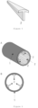
- Figs. 1A to 1D illustrate a typical joint
- Figs. 2A to 2D illustrate an integrated molded component in which the structural member (a) (hollow columnar body) and the joint are integrated
- Figs. 3A to 3B illustrate a typical pedestal
- Figs. 4A to 4B illustrate an integrated molded component in which the structural member (a) (hollow columnar body) and the pedestal are integrated
- Fig. 5 illustrates a typical rib
- Figs. 6A to 6B illustrate a schematic view of an integrated molded component in which the structural member (a) (hollow columnar body) and the rib are integrated, but the respective structures are not limited thereto.
- the resin structural member (b) may be a member consisting essentially of a thermosetting resin.
- the thermosetting resin is not particularly limited, and examples thereof include an unsaturated polyester resin, a vinyl ester resin, an epoxy resin, a phenol (resol type) resin, a urea melamine resin, a polyimide resin, copolymers and modified products thereof, and resins obtained by blending at least two of these, as with the structural member (a).
- the thermosetting resin containing an epoxy resin as a main component is more preferable from the viewpoint of mechanical characteristics of the molded component because of excellent rigidity and strength.
- other fillers and additives may be contained depending on the use and the like.
- Examples thereof include an elastomer or a rubber component, an inorganic filler, a flame retardant, a conductivity imparting agent, an antibacterial agent, an insect repellent, a deodorant, a coloring inhibitor, a mold release agent, an antistatic agent, a plasticizer, a coloring agent, a pigment, a dye, a foaming agent, an antifoaming agent, and a coupling agent.
- the resin structural member (b) when the resin structural member (b) consists essentially of a thermosetting resin, the resin structural member (b) may have a thermoplastic resin region in which the thermoplastic resin is exposed on at least a portion of the surface thereof.
- the structural member (a) and the resin structural member (b) can be bonded to each other by thermal welding with the thermoplastic resin region interposed therebetween.
- both the structural member (a) and the resin structural member (b) have such a thermoplastic resin region, and the thermoplastic resin region of the structural member (a) and the thermoplastic resin region of the resin structural member (b) are bonded by thermal welding.
- both the structural member (a) and the resin structural member (b) have a thermoplastic resin region
- both the structural member (a) and the resin structural member (b) have the same kind of thermoplastic resin region from the viewpoint of bonding strength between the structural member (a) and the resin structural member (b).
- thermoplastic resin region is typically provided thinly on the surface of the resin structural member (b), and the thickness thereof is usually 1 to 300 um and more preferably 50 to 150 um.
- the form of the thermoplastic resin region is not particularly limited as long as a region where the thermoplastic resin is exposed is formed on the surface of the resin structural member (b), and examples thereof include a layered shape, a spot shape, a mesh shape, and a lattice shape.
- the resin structural member (b) consists essentially of a thermosetting resin
- the resin structural member (b) is preferably a hollow columnar body.
- the hollow columnar body is a hollow columnar body having a length, a diameter, a thickness, and the like different from those of the hollow columnar portion or the solid columnar portion of the structural member (a).
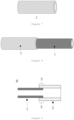
- Fig. 7 illustrates a schematic view of a representative hollow columnar body
- Fig. 8 illustrates a schematic view of an integrated molded component in which a structural member (a)1 (first hollow columnar body) and a resin structural members (b)2 (second hollow columnar body) are integrated, but the respective structures are not limited thereto.
- the resin structural member (b) consists essentially of a thermosetting resin
- the shape change of each member due to heat input at the time of bonding is extremely small, an integrated molded component with high dimensional accuracy is obtained, and the concentricity indicating the center deviation of the cross sections of the structural member (a) and the resin structural member (b) is preferably 0.25 mm or less.
- the concentricity can be measured by measuring positions of three outer diameter points of each of the structural member (a) and the resin structural member (b) using a CNC three-dimensional measuring machine and comparing center positions obtained from the positions.
- the resin structural member (b) may contain reinforcing fibers in order to improve the mechanical characteristics.
- the reinforcing fibers include fibers selected from the same options as those of the fiber-reinforced thermosetting resin constituting the structural member (a) described above, and carbon fibers are preferable from the viewpoint of the lightweight properties and the mechanical characteristics. These fibers may be subjected to a surface treatment such as a treatment with a coupling agent, a treatment with a sizing agent, or an additive adhesion treatment.
- the mass content of fibers present in 100% by mass of the resin structural member (b) is preferably 20% to 70% by mass, more preferably 25% to 70% by mass, and particularly preferably 30% to 65% by mass. By setting the mass content of the fiber within the above range, the resin structural member (b) having high rigidity and good dimensional accuracy can be obtained.
- the reinforcing fibers contained in the resin structural member (b) are preferably discontinuous reinforcing fibers from the viewpoint of molding processability.
- a mass average fiber length Lw of the reinforcing fibers is preferably 0.3 mm or more and more preferably 0.8 mm or more.
- the longer the mass average fiber length the higher the effect of improving strength and rigidity, and in particular, the effect of significantly improving impact strength can be obtained.
- the upper limit of the mass average fiber length Lw is preferably 3.0 mm or less, more preferably 1.5 mm or less, and particularly preferably 1.0 mm or less.
- the mass average fiber lengths of the resin structural member (b) of the present invention are not all the same, and may have a fiber length distribution.
- the resin structural member (b) has an overlap region overlapping the outer peripheral portion and/or the inner peripheral portion of the hollow columnar portion or the solid columnar portion of the structural member (a), and is bonded to the structural member (a) by thermal welding via a thermoplastic resin in at least a portion of the overlap region.
- the fact that the resin structural member (b) overlaps the outer peripheral surface and/or the inner peripheral surface of the hollow columnar portion of the structural member (a) means that the outer peripheral surface or the inner peripheral surface of the hollow columnar portion of the structural member (a), or both surfaces thereof, and at least a portion of the resin structural member (b) are in surface contact with each other.
- the fact that the resin structural member (b) overlaps the outer peripheral surface of the solid columnar portion of the structural member (a) means that the outer peripheral surface of the solid columnar portion of the structural member (a) and at least a portion of the resin structural member (b) are in surface contact with each other.
- the overlap region means a region in contact with the overlap region.
- Fig. 9 illustrates an embodiment in which a joint 2 is bonded to the outer peripheral surface of the structural member (a)1 as the resin structural member (b), but in this embodiment, the inner peripheral surface of the hollow columnar resin structural member (b) is in contact with the outer peripheral surface of the structural member (a) so as to surround the entire circumference of the outer peripheral surface of the structural member (a).
- the resin structural member (b) overlaps the structural member (a) on the entire circumference thereof.
- the resin structural member (b) may be in contact with only a portion of the outer peripheral surface or the inner peripheral surface of the structural member (a) instead of the entire periphery of the outer peripheral surface or the inner peripheral surface.
- the integrated molded component may include both the resin structural member (b) that is bonded to the outer peripheral surface in an overlapping manner and the resin structural member (b) that is bonded to the inner peripheral surface in an overlapping manner.
- the thermoplastic resin is preferably present on the surface of the structural member (a) positioned on the structural member (a) side from the bonding boundary surface.
- a state in which the thermoplastic resin is present on the surface of the structural member (a) positioned on the structural member (a) side from the bonding boundary surface refers to a state in which the thermoplastic resin is present on the structural member (a) side from a line, as the bonding boundary surface, forming the outer periphery of the hollow columnar portion or the solid columnar portion of the structural member (a) in the cross section of the bonded portion.
- a portion of the fiber included in the structural member (a) is in contact with both the thermosetting resin and the thermoplastic resin region of the structural member (a) in a state of straddling the thermosetting resin and the thermoplastic resin region constituting the structural member (a).
- the bonding strength between the structural member (a) and the resin structural member (b) of the present invention is preferably 7 MPa or more and more preferably 10 MPa or more.
- the upper limit of the bonding strength is not particularly limited, and is preferably 100 MPa or less from the viewpoint of obtaining the integrated molded component of the present invention with high productivity.
- the integrated molded component including the structural member (a) and the resin structural member (b) of the present invention can be manufactured by bonding the structural member (a) and the resin structural member (b) by thermal welding by bringing at least one of the members into contact with each other in a heated state.
- thermal welding method is not particularly limited, and can be integrated by hot plate welding, vibration welding, ultrasonic welding, far infrared ray thermal welding, dielectric thermal welding, laser welding, insert molding, outsert injection molding, or the like.
- the resin structural member (b) consists essentially of a thermoplastic resin
- insert molding is preferable in that an integrated molded component that is particularly firmly bonded can be manufactured with high productivity.
- the resin structural member (b) is molded and integrated by performing clamping in a state where the structural member (a) is inserted into an injection molding mold, and performing injection molding such that the thermoplastic resin of the resin structural member (b) overlaps the outer peripheral portion or the inner peripheral portion of the structural member (a).
- the resin structural member (b) may be brought into contact with the outer peripheral surface or the inner peripheral surface of the structural member (a) in a state where the structural member (a) or the resin structural member (b) having the thermoplastic resin region is heated, so that the structural member (a) and the resin structural member (b) are bonded to each other by thermal welding.
- thermal welding examples include far infrared ray thermal welding.
- the integrated molded component can be manufactured in such a manner that the structural member (a) and the resin structural member (b) are molded in advance, and then the resin structural member (b) is brought into contact with the outer peripheral portion or the inner peripheral portion of the structural member (a) so as to overlap with the outer peripheral portion or the inner peripheral portion of the structural member (a) in a state where the structural member (a) is heated, and the resin structural member (b) is cooled and solidified.
- the structural member (a) is preferably heated by a far infrared heater, to a temperature equal to or higher than a temperature at which the thermoplastic resin contained in the resin structural member (b) melts and softens.
- the integrated molded component can be manufactured by, as an example, a method for preparing a structural member (a) having a thermoplastic resin region on at least a portion of an outer peripheral surface or an inner peripheral surface of a hollow columnar portion or a solid columnar portion and/or a resin structural member (b) having a thermoplastic resin region on at least a portion of a surface, and bringing the structural member (a) and the resin structural member (b) into contact with each other in a heated state of the thermoplastic resin region such that the structural member (a) and the resin structural member (b) overlap each other in a region including the heated thermoplastic resin region.
- thermoplastic resin constituting the thermoplastic resin region of the structural member (a) or the resin structural member (b) it is preferable to heat the thermoplastic resin constituting the thermoplastic resin region of the structural member (a) or the resin structural member (b) to a temperature equal to or higher than a temperature at which the thermoplastic resin is softened, and it is more preferable to heat the thermoplastic resin to a temperature equal to or higher than a temperature at which the thermoplastic resin is melted.
- the integrated molded component of the present invention can also be manufactured by a method for injection-molding a thermoplastic resin between the overlapping structural member (a) and resin structural member (b) in a state where the structural member (a) and the resin structural member (b) are inserted into an injection molding mold such that the resin structural member (b) overlaps an outer peripheral surface and/or an inner peripheral surface of a hollow columnar portion or a solid columnar portion of the structural member (a).
- Fig. 10 is a schematic view of an embodiment in which a second hollow columnar body 2 as a resin structural member (b) is bonded to an outer peripheral surface of a structural member (a)1 as a first hollow columnar body via an injection-molded thermoplastic resin 4, and Fig.
- thermoplastic resin 4 only needs to be interposed between the outer peripheral surface and/or the inner peripheral surface of the hollow columnar portion or the solid columnar portion of the structural member (a) and the surface of the resin structural member (b), and is not limited to this drawing.
- the thermoplastic resin species for injection molding in this case, the same resin as the resin described above can be used as the thermoplastic resin constituting the resin structural member (b).
- the thermoplastic resin for injection molding may contain reinforcing fibers in order to improve the mechanical characteristics.
- the reinforcing fibers include fibers selected from the same options as those of the fiber-reinforced thermosetting resin constituting the structural member (a) described above, and carbon fibers are preferable from the viewpoint of the lightweight properties and the mechanical characteristics. These fibers may be subjected to a surface treatment such as a treatment with a coupling agent, a treatment with a sizing agent, or an additive adhesion treatment.
- the integrated molded component of the present invention can be suitably used as a member forming a frame structure because the resin structural member (b) capable of performing connection, joining, branching, stationary, and the like is firmly bonded to the lightweight and highly rigid structural member (a).
- a structure include a body and an arm of an industrial robot, a body and an arm of an automobile, a motorcycle, a bicycle, an aircraft, a helicopter, a drone, a ship, a submersible, and the like, a building material, and the like.
- a flying object such as an aircraft, a helicopter, and a drone.
- an integrated molded component in which the length of the hollow columnar portion or the solid columnar portion of the structural member (a) is 0.05 m or more and 3 m or less is more preferable.
- the integrated molded component of the present invention can be particularly suitably used because the influence of weight increase due to mechanical fastening such as bolts and fasteners is large.
- TORAYCA Prepreg P3051S-30 and P3052S-12 manufactured by Toray Industries, Inc. were used in a release-treated stainless mandrel having a tip outer diameter of 30 mm, a taper -6.0/1000, and a length of 700 mm.
- a longitudinal direction of the mandrel was set to an axis of 0 degrees
- P3051S-30 was stacked so that a material angle was 0 degrees
- P3052S-12 was stacked so that the material angle was 60 degrees.
- a 70 umthick polyamide film obtained by hot-pressing pellets of a copolymer polyamide resin (CM4000 manufactured by Toray Industries, Inc., polyamide 6/66/610, melting point: 150°C) was wound around the outer side of the laminate by one turn, a wrapping tape (heat-resistant film tape, width 10 mm) was wound around the laminate at a tension of 3 kg, and the laminate was heat-molded in a curing furnace at 150°C for 30 minutes. Thereafter, the mandrel was removed, the wrapping tape was removed, and the resulting product was cut to obtain a pipe 1 having a thickness of 0.5 mm and a length of 500 mm.
- CM4000 manufactured by Toray Industries, Inc., polyamide 6/66/610, melting point: 150°C copolymer polyamide resin
- a wrapping tape heat-resistant film tape, width 10 mm
- the pipe was inserted into an injection molding mold using an injection molding machine (J 350EIII manufactured by The Japan Steel Works, Ltd.) set at a cylinder temperature of 280°C and a mold temperature of 80°C, and the joint illustrated in Fig. 1A was injection-molded using a long fiber pellet (TLP1060) manufactured by Toray Industries, Inc. so as to be in contact with the outer peripheral surface of a region 10 mm from an end portion of the outer peripheral surface of the pipe to manufacture an integrated molded component as illustrated in Fig. 2A .
- J 350EIII manufactured by The Japan Steel Works, Ltd.
- the bonded portion and the pipe were gripped with a jig, and a tensile test was conducted at a test speed of 0.5 mm/min at room temperature using a universal testing machine manufactured by Instron.
- a pipe 1 was obtained in the same manner as in Example 1. Subsequently, by using an injection molding machine (J 350EIII manufactured by The Japan Steel Works, Ltd.) set at a cylinder temperature of 280°C and a mold temperature of 80°C, the joint illustrated in Fig. 1A was independently injection-molded using long fiber pellets (TLP1060) manufactured by Toray Industries, Inc. which are pellets of carbon fiber-reinforced polyamide 6.
- J 350EIII manufactured by The Japan Steel Works, Ltd.
- the joint was immediately pressed against the pipe at a pressure of 1 MPa for 15 seconds in a state where 10 mm from the end portion of the outer peripheral surface of the pipe and the inner peripheral surface were in contact with each other, and then cooled to produce an integrated molded component as illustrated in Fig. 2A .
- the bonding strength was evaluated in the same manner as in Example 1, and consequently the bonding strength was 41 MPa, which was a good joint state.
- a 70 ⁇ m-thick polyamide film obtained by hot-pressing pellets of a copolymerized polyamide resin (CM4000 manufactured by Toray Industries, Inc., polyamide 6/66/610, melting point: 150°C) was wound one turn around a release-treated stainless mandrel having a tip outer diameter of 30 mm, a taper -6.0/1000, and a length of 700 mm.
- CM4000 manufactured by Toray Industries, Inc., polyamide 6/66/610, melting point: 150°C was wound one turn around a release-treated stainless mandrel having a tip outer diameter of 30 mm, a taper -6.0/1000, and a length of 700 mm.
- a rib as illustrated in Fig. 5 was independently injection-molded using long fiber pellets (TLP1060) manufactured by Toray Industries, Inc. which are pellets of carbon fiber-reinforced polyamide 6.
- the rib was immediately pressed against the heated inner peripheral surface of the pipe at a pressure of 1 MPa for 15 seconds, and then cooled to manufacture an integrated molded component as illustrated in Fig. 6 .
- a pipe 1 was molded in the same manner as in Example 1. Next, a 70 ⁇ m-thick polyamide film obtained by hot-pressing pellets of a copolymerized polyamide resin (CM4000 manufactured by Toray Industries, Inc., polyamide 6/66/610, melting point: 150°C) was wound one turn around a release-treated stainless mandrel having a tip outer diameter of 31 mm, a taper -6.0/1000, and a length of 700 mm.
- CM4000 manufactured by Toray Industries, Inc., polyamide 6/66/610, melting point: 150°C
- the end portion of the pipe 1 was heated to a surface temperature of 230°C using a far infrared heater, and then the pipe 3 was immediately pressed against the pipe 1 for 15 seconds in a state where 10 mm from the end portion of the outer peripheral surface of the pipe 1 and the inner peripheral surface were in contact with each other, and then cooled to produce an integrated molded component as illustrated in Fig. 8 .
- the concentricity was evaluated by comparing the center positions obtained by measuring the positions of three points of the outer diameter of each of the pipes 1 and 3 using a CNC three-dimensional measuring machine CRYSTA Apex S9108 manufactured by Mitutoyo Corporation, and the concentricity was as high as 0.16 mm with high dimensional accuracy.
- the pipe 1 was molded in the same manner as in Example 1, and then the pipe 4 was molded in the same manner as in Example 1 except that the outer diameter of the tip end of the stainless mandrel was changed to 32 mm.
- the pipe 1 and the pipe 4 were inserted into the mold using an injection molding machine (J 350EIII manufactured by The Japan Steel Works, Ltd.) set at a cylinder temperature of 280°C and a mold temperature of 80°C.
- a long fiber pellet (TLP1060) manufactured by Toray Industries, Inc. which was a pellet of carbon fiber-reinforced polyamide 6 inserted at a position where 10 mm from the end portion of the outer peripheral surface of the pipe 1 entered the inside of the pipe 4, was injection-molded between the pipe 1 and the pipe 4 to obtain an integrated molded component as illustrated in Fig. 10 .
- a pipe 1 and a joint were manufactured in the same manner as in Example 2.
- a two-pack type epoxy adhesive (SWANBOND 4000 manufactured by Takada Chemical Products Mfg. Co., Ltd.)
- equal amounts of two liquids were uniformly mixed at room temperature, and immediately applied to the outer peripheral surface of 10 mm from the end portion of the pipe 1, and in a state where 10 mm from the end portion of the outer peripheral surface of the pipe 1 and the inner peripheral surface were in contact with each other, the joint was fitted to the pipe 1 and fixed with a vise, and bonded at 25°C for 24 hours to produce an integrated molded component.
- the bonding strength was evaluated in the same manner as in Example 1, and the result was 5 MPa.
- a pipe 1 and a pipe 3 were manufactured in the same manner as in Example 4.
- An integrated molded component was manufactured in the same manner as in Comparative Example 1 using a two-pack epoxy adhesive (SWANBOND 4000 manufactured by Takada Chemical Products Mfg. Co., Ltd.).
Landscapes
- Engineering & Computer Science (AREA)
- Mechanical Engineering (AREA)
- Manufacturing & Machinery (AREA)
- Chemical & Material Sciences (AREA)
- Composite Materials (AREA)
- Laminated Bodies (AREA)
- Injection Moulding Of Plastics Or The Like (AREA)
- Lining Or Joining Of Plastics Or The Like (AREA)
Applications Claiming Priority (3)
| Application Number | Priority Date | Filing Date | Title |
|---|---|---|---|
| JP2022044935 | 2022-03-22 | ||
| JP2022044934 | 2022-03-22 | ||
| PCT/JP2023/010371 WO2023182158A1 (ja) | 2022-03-22 | 2023-03-16 | 一体化成形品および一体化成形品の製造方法 |
Publications (2)
| Publication Number | Publication Date |
|---|---|
| EP4497579A1 true EP4497579A1 (de) | 2025-01-29 |
| EP4497579A4 EP4497579A4 (de) | 2026-03-18 |
Family
ID=88101504
Family Applications (1)
| Application Number | Title | Priority Date | Filing Date |
|---|---|---|---|
| EP23774754.8A Pending EP4497579A4 (de) | 2022-03-22 | 2023-03-16 | Integrierte geformte komponente und verfahren zur herstellung einer integrierten geformten komponente |
Country Status (6)
| Country | Link |
|---|---|
| US (1) | US20250178290A1 (de) |
| EP (1) | EP4497579A4 (de) |
| JP (1) | JPWO2023182158A1 (de) |
| KR (1) | KR20240165338A (de) |
| TW (1) | TW202338451A (de) |
| WO (1) | WO2023182158A1 (de) |
Families Citing this family (1)
| Publication number | Priority date | Publication date | Assignee | Title |
|---|---|---|---|---|
| CN120548246A (zh) * | 2023-01-31 | 2025-08-26 | 东丽株式会社 | 一体化成型品及一体化成型品的制造方法 |
Family Cites Families (7)
| Publication number | Priority date | Publication date | Assignee | Title |
|---|---|---|---|---|
| JPS62295372A (ja) | 1986-06-12 | 1987-12-22 | 三菱電機株式会社 | 炭素繊維強化プラスチツク構造体のフレ−ム帯電防止方法 |
| JPH06114876A (ja) * | 1992-09-22 | 1994-04-26 | Chen Shun-Sen | 複合材料製の自転車フレームとその作製方法 |
| JPH11350592A (ja) | 1998-06-11 | 1999-12-21 | Ohbayashi Corp | トラス部材の接合構造 |
| JP2007168231A (ja) * | 2005-12-21 | 2007-07-05 | Toho Tenax Co Ltd | Frp製の長尺薄物の多段成形方法 |
| JP6991483B2 (ja) * | 2018-02-20 | 2022-01-12 | 有限会社文殊工学医学研究所 | 炭素繊維強化熱可塑性樹脂複合材料の製造方法 |
| JP7421312B2 (ja) * | 2019-11-21 | 2024-01-24 | 積水化学工業株式会社 | 配管構造用の樹脂成形体及びその製造方法 |
| JP7365100B2 (ja) * | 2019-12-10 | 2023-10-19 | 三光合成株式会社 | ロボットアーム、ロボットアームインサート射出成形用金型及びロボットアームインサート射出成形方法 |
-
2023
- 2023-03-16 KR KR1020247029221A patent/KR20240165338A/ko active Pending
- 2023-03-16 EP EP23774754.8A patent/EP4497579A4/de active Pending
- 2023-03-16 WO PCT/JP2023/010371 patent/WO2023182158A1/ja not_active Ceased
- 2023-03-16 US US18/846,401 patent/US20250178290A1/en active Pending
- 2023-03-16 JP JP2023517868A patent/JPWO2023182158A1/ja active Pending
- 2023-03-20 TW TW112110171A patent/TW202338451A/zh unknown
Also Published As
| Publication number | Publication date |
|---|---|
| US20250178290A1 (en) | 2025-06-05 |
| KR20240165338A (ko) | 2024-11-22 |
| EP4497579A4 (de) | 2026-03-18 |
| WO2023182158A1 (ja) | 2023-09-28 |
| JPWO2023182158A1 (de) | 2023-09-28 |
| TW202338451A (zh) | 2023-10-01 |
Similar Documents
| Publication | Publication Date | Title |
|---|---|---|
| US12226961B2 (en) | Preform charges and fixtures therefor | |
| US9339988B2 (en) | Joined body | |
| EP3260280A1 (de) | Verfahren zur herstellung von thermoplastischen verbundwerkstoffen unter verwendung von gewebebasierten thermoplastischen prepregs | |
| US20180326678A1 (en) | Improvements in or relating to fibre reinforced composites | |
| JP7615683B2 (ja) | プリプレグ、積層体および成形品 | |
| EP4497579A1 (de) | Integrierte geformte komponente und verfahren zur herstellung einer integrierten geformten komponente | |
| KR20180131535A (ko) | 강화 섬유 적층 시트 및 섬유 강화 수지 성형체 및 강화 섬유 적층 시트의 제조 방법 | |
| CN116438229B (zh) | 纤维增强树脂基材、预制件、一体化成型品及纤维增强树脂基材的制造方法 | |
| EP0185460A2 (de) | Rückstellbarer Verbundwerkstoff und Verfahren zu dessen Herstellung | |
| CN113226717A (zh) | 模制复合肋条及肋条-片材的方法和设备 | |
| KR20150009976A (ko) | 금속 인서트 수지 성형품의 제조 방법 | |
| GB2548184A (en) | Improvements in or relating to electrically conducting materials | |
| WO2022024939A1 (ja) | 繊維強化プラスチック及び繊維強化プラスチックの製造方法 | |
| EP4691742A1 (de) | Integriertes formteil und verfahren zur herstellung des integrierten formteils | |
| EP4659932A1 (de) | Integral geformtes produkt und verfahren zur herstellung eines integral geformten produkts | |
| CN118715113A (zh) | 一体化成形品及一体化成形品的制造方法 | |
| JP2019111710A (ja) | 炭素繊維テープ材及びその積層シート基材 | |
| JP2024108259A (ja) | 一体化成形品の製造方法 | |
| WO2026071057A1 (ja) | フレーム構造体、飛翔体およびフレーム構造体の製造方法 | |
| JP2025121470A (ja) | 繊維強化樹脂成形品の製造方法 | |
| WO2017089460A1 (en) | Improvements in or relating to fibre reinforced composites | |
| JP2025121471A (ja) | 繊維強化樹脂成形品の製造方法 | |
| JP2024082914A (ja) | Frp成形品を製造する方法 | |
| EP3380310A1 (de) | Verbesserungen an oder im zusammenhang mit faserverstärkten verbundwerkstoffen |
Legal Events
| Date | Code | Title | Description |
|---|---|---|---|
| STAA | Information on the status of an ep patent application or granted ep patent |
Free format text: STATUS: THE INTERNATIONAL PUBLICATION HAS BEEN MADE |
|
| PUAI | Public reference made under article 153(3) epc to a published international application that has entered the european phase |
Free format text: ORIGINAL CODE: 0009012 |
|
| STAA | Information on the status of an ep patent application or granted ep patent |
Free format text: STATUS: REQUEST FOR EXAMINATION WAS MADE |
|
| 17P | Request for examination filed |
Effective date: 20240906 |
|
| AK | Designated contracting states |
Kind code of ref document: A1 Designated state(s): AL AT BE BG CH CY CZ DE DK EE ES FI FR GB GR HR HU IE IS IT LI LT LU LV MC ME MK MT NL NO PL PT RO RS SE SI SK SM TR |
|
| DAV | Request for validation of the european patent (deleted) | ||
| DAX | Request for extension of the european patent (deleted) | ||
| REG | Reference to a national code |
Ref country code: DE Ref legal event code: R079 Free format text: PREVIOUS MAIN CLASS: B29C0065400000 Ipc: B29C0045160000 |
|
| A4 | Supplementary search report drawn up and despatched |
Effective date: 20260213 |
|
| RIC1 | Information provided on ipc code assigned before grant |
Ipc: B29C 45/16 20060101AFI20260209BHEP Ipc: B29C 65/40 20060101ALI20260209BHEP Ipc: B29C 45/14 20060101ALI20260209BHEP Ipc: B29C 65/70 20060101ALI20260209BHEP Ipc: B29C 70/68 20060101ALI20260209BHEP Ipc: B29C 65/00 20060101ALI20260209BHEP Ipc: F16K 27/00 20060101ALI20260209BHEP |