EP4496136A1 - Abdeckkasten zum schutz einer elektrischen verbindung, anordnung und zugehöriges verfahren - Google Patents
Abdeckkasten zum schutz einer elektrischen verbindung, anordnung und zugehöriges verfahren Download PDFInfo
- Publication number
- EP4496136A1 EP4496136A1 EP23306237.1A EP23306237A EP4496136A1 EP 4496136 A1 EP4496136 A1 EP 4496136A1 EP 23306237 A EP23306237 A EP 23306237A EP 4496136 A1 EP4496136 A1 EP 4496136A1
- Authority
- EP
- European Patent Office
- Prior art keywords
- shell
- cover box
- electrical connection
- latching means
- shells
- Prior art date
- Legal status (The legal status is an assumption and is not a legal conclusion. Google has not performed a legal analysis and makes no representation as to the accuracy of the status listed.)
- Pending
Links
Images



Classifications
-
- H—ELECTRICITY
- H02—GENERATION; CONVERSION OR DISTRIBUTION OF ELECTRIC POWER
- H02G—INSTALLATION OF ELECTRIC CABLES OR LINES, OR OF COMBINED OPTICAL AND ELECTRIC CABLES OR LINES
- H02G15/00—Cable fittings
- H02G15/02—Cable terminations
- H02G15/06—Cable terminating boxes, frames or other structures
-
- H—ELECTRICITY
- H02—GENERATION; CONVERSION OR DISTRIBUTION OF ELECTRIC POWER
- H02G—INSTALLATION OF ELECTRIC CABLES OR LINES, OR OF COMBINED OPTICAL AND ELECTRIC CABLES OR LINES
- H02G3/00—Installations of electric cables or lines or protective tubing therefor in or on buildings, equivalent structures or vehicles
- H02G3/02—Details
- H02G3/08—Distribution boxes; Connection or junction boxes
- H02G3/081—Bases, casings or covers
-
- H—ELECTRICITY
- H01—ELECTRIC ELEMENTS
- H01R—ELECTRICALLY-CONDUCTIVE CONNECTIONS; STRUCTURAL ASSOCIATIONS OF A PLURALITY OF MUTUALLY-INSULATED ELECTRICAL CONNECTING ELEMENTS; COUPLING DEVICES; CURRENT COLLECTORS
- H01R13/00—Details of coupling devices of the kinds covered by groups H01R12/70 or H01R24/00 - H01R33/00
- H01R13/46—Bases; Cases
- H01R13/502—Bases; Cases composed of different pieces
-
- H—ELECTRICITY
- H01—ELECTRIC ELEMENTS
- H01R—ELECTRICALLY-CONDUCTIVE CONNECTIONS; STRUCTURAL ASSOCIATIONS OF A PLURALITY OF MUTUALLY-INSULATED ELECTRICAL CONNECTING ELEMENTS; COUPLING DEVICES; CURRENT COLLECTORS
- H01R13/00—Details of coupling devices of the kinds covered by groups H01R12/70 or H01R24/00 - H01R33/00
- H01R13/40—Securing contact members in or to a base or case; Insulating of contact members
-
- H—ELECTRICITY
- H01—ELECTRIC ELEMENTS
- H01R—ELECTRICALLY-CONDUCTIVE CONNECTIONS; STRUCTURAL ASSOCIATIONS OF A PLURALITY OF MUTUALLY-INSULATED ELECTRICAL CONNECTING ELEMENTS; COUPLING DEVICES; CURRENT COLLECTORS
- H01R13/00—Details of coupling devices of the kinds covered by groups H01R12/70 or H01R24/00 - H01R33/00
- H01R13/46—Bases; Cases
- H01R13/502—Bases; Cases composed of different pieces
- H01R13/506—Bases; Cases composed of different pieces assembled by snap action of the parts
-
- H—ELECTRICITY
- H01—ELECTRIC ELEMENTS
- H01R—ELECTRICALLY-CONDUCTIVE CONNECTIONS; STRUCTURAL ASSOCIATIONS OF A PLURALITY OF MUTUALLY-INSULATED ELECTRICAL CONNECTING ELEMENTS; COUPLING DEVICES; CURRENT COLLECTORS
- H01R43/00—Apparatus or processes specially adapted for manufacturing, assembling, maintaining, or repairing of line connectors or current collectors or for joining electric conductors
- H01R43/18—Apparatus or processes specially adapted for manufacturing, assembling, maintaining, or repairing of line connectors or current collectors or for joining electric conductors for manufacturing bases or cases for contact members
-
- H—ELECTRICITY
- H02—GENERATION; CONVERSION OR DISTRIBUTION OF ELECTRIC POWER
- H02G—INSTALLATION OF ELECTRIC CABLES OR LINES, OR OF COMBINED OPTICAL AND ELECTRIC CABLES OR LINES
- H02G3/00—Installations of electric cables or lines or protective tubing therefor in or on buildings, equivalent structures or vehicles
- H02G3/02—Details
- H02G3/08—Distribution boxes; Connection or junction boxes
- H02G3/14—Fastening of cover or lid to box
-
- H—ELECTRICITY
- H01—ELECTRIC ELEMENTS
- H01R—ELECTRICALLY-CONDUCTIVE CONNECTIONS; STRUCTURAL ASSOCIATIONS OF A PLURALITY OF MUTUALLY-INSULATED ELECTRICAL CONNECTING ELEMENTS; COUPLING DEVICES; CURRENT COLLECTORS
- H01R4/00—Electrically-conductive connections between two or more conductive members in direct contact, i.e. touching one another; Means for effecting or maintaining such contact; Electrically-conductive connections having two or more spaced connecting locations for conductors and using contact members penetrating insulation
- H01R4/28—Clamped connections, spring connections
- H01R4/38—Clamped connections, spring connections utilising a clamping member acted on by screw or nut
Definitions
- the present disclosure pertains to the field of electrical connection, and cover boxes to protect them, for example from the reach of a user to avoid accidents.
- electrical connections may be of different sizes depending on the number of cables that are assembled. Different sizes of connections thus mean different sizes and sometimes different shapes of cover boxes which imply non negligeable cost.
- the present disclosure aims at reducing at least part of the disadvantages described above.
- the present disclosure concerns a cover box, for protecting an electrical connection, the cover box comprising a first and a second half-shell delimiting an interior volume configured to accommodate at least part of the electrical connection, each half-shell comprising:
- This solution provides a secure cover box that requires simple design and minimum cost. Also, the box is held in place by the cooperation between the recesses and the screw and nut, which rarely vary in size. It is therefore possible to use the same cover box for different thickness of electrical connection.
- the cover box according to the present disclosure is thus usable on a great variety of electrical connections provided they comprise a screw and a nut.
- the cover box may be dimensioned to allow application on a large variety of electrical connections.
- the cover box may be designed in for example 2, 3 or more sizes that may cover the majority of electrical connections. Therefore, a variation of size from one electrical connection to the other may at most imply the use of a different available size, instead of having to specifically design a new cover for each different connection.
- Such a solution does not need any additional fixation part to cover the electrical connection and is thus easy to mount, manufacture and maintain.
- Both half-shells may be obtained with molded plastic, for example by injection molding.
- the plastic material can be polyethylene or polycarbonate.
- said cover box does not comprise any opening larger than 12,5 mm, once both half-shells are latched together. This allows to meet the IP20 safety requirements that may prevent the reach of the electrical parts inside the cover box by a smaller object, or by a user, for example a user's finger.
- each half-shell is generally parallelepiped-shaped comprising 4 outer walls, and a base wall defining an open volume on one side that remains open.
- Said open side of the first half-shell may comprise a contour designed to accommodate the open side of a second half-shell.
- the contour of the first half-shell may be complementary to the contour of the second half-shell to continuously close the gap between both half-shells.
- each half-shell may comprise an elongation direction, going from one smaller side to the other, a transversal direction going from one bigger side to the other, and a vertical direction going from the base through the opposite open side.
- each half-shell may comprise an outer wall that is opened to let one or more connective parts of the electrical connection through the cover box.
- a contour of an opened volume defined by each half-shell may be interrupted by a shorter outer wall to provide an open space in which one or more conductive part can be accommodated. This allows to close the cover box around an electrical connection that comprises for example one or more bar.
- each half shell may comprise another opening, said contour being interrupted again, to let another conductive part through, for example one or more cables.
- the recess can be of any shape provided it can accommodate the nut and/or the screw head to prevent the latched together half-shells from being pulled or move away from the electrical connection.
- the recess is not meant to prevent the rotation of the cover box around the screw of the electrical connection but is at least meant to comprise a surface to block any movement away from the screw along the one or more cable.
- the recess can be a cylindrical shaft protruding from the surface than defines the interior volume inside the cover box in such a way that the recess of each half-shell can face each-other when latched together. In an embodiment, it can be a well without any protruding walls.
- the recess can comprise an opening with a circular cross-section, in which a hexagonal nut can be lodged.
- the recess can comprise any polygonal cross-section provided it can accommodate a nut or a screw head.
- the recess feature a cross section, for example a circular cross-section, that allow for a small rotary travel of the connection, which may prevent early breakage of the cover box when hustled by operations on the cables of the electrical connection or on surrounding equipment.
- the recess may comprise a depth that is determined to allow the accommodation of at least part of the nut in addition to the overlength part of the screw that extends passed the nut.
- first and second half shells are identical. This means they comprise the same shape and the same dimensions.
- both half-shells can typically be made in the same mold, or in identical molds.
- the latching means of each half shell may comprise a male and a female part, each located on an opposite side of the half-shell, the male part respectively the female part of the first half-shell being configured to meet the female part respectively the male part of the second half-shell.
- the latching means comprising a tab and a notch, the tab, respectively the notch, of the first half-shell being able to cooperate with the notch, respectively the tab, of the second half-shelf.
- the latching means are configured to cooperate with one another by an elastic deformation of at least one part.
- the latching means being then configured to disassemble by elastic deformation of the same, or another deformable part.
- the tab may be elastically deformable and protrude vertically from the half-shell, for example from an outer wall, and comprise a free end.
- the free end may comprise a tooth or any protrusion with a stopping surface. The elastic deformation of the tab allowing the protrusion to be at least mobile along a transversal direction of the cover box.
- each half-shell may comprise a hollow sleeve elongating vertically and comprising two openings at its ends configured to let all the way through the elongated tab of the other half-shell, the tooth comprising a biased surface to force the tab out of a resting state when let through the sleeve to a bending state, the sleeve then comprising a stopping edge configured to block the stopping surface of the tooth when the tab comes back to its resting state, the cooperation between the stopping surface and the stopping edge preventing the two half-shells from disassembling.
- the latching means may comprise two safety walls elongating vertically on both sides of the latching means, the safety walls being located at a distance from each other, thus preventing objects that are bigger than that distance to pass between the safety walls and reach the latching means. Said distance may be determined in accordance to the objects one wishes to prevent the intrusion.
- the latching means are configured to be disassembled by deformation of at least one part
- such safety walls are particularly useful to prevent a user from disassembling the latching means.
- the distance between both safety walls may be inferior to the size of a finger, for example 12,5mm.
- the safety walls may be located at such a distance that prevents the intrusion of a finger but permits the intrusion of a smaller tool, for example a screwdriver, that a permitted user may be in possession of, for example to bend the latching means back and to allow the opening of the cover box for determined purposes, for example emergency reasons or maintainability.
- Each safety wall comprising a first and a second part, the first half-shell comprising the first part, the second half-shell comprising the second part, both parts of each safety wall defining an extension of each other when the first and second half-shells are assembled.
- Such an embodiment help prevent to manufacture too long protruding parts that may break during transportation of mounting.
- Designing a second part for each safety walls allow to add length for the part without increasing the risk of breakage.
- shorter protrusions allow an easier demolding operation minimizing the risk of featuring undercuts.
- the two safety walls may comprise biased guiding surfaces defining two slopes leading to the space between the two safety walls, the guiding surfaces of a first half-shell being able to guide the latching means of a second half-shell between the two safety walls.
- the guiding surfaces may be of the shape of a chamfer or may comprise a radius, or any shape that may induce a centering function, to lead the movement of cooperating latching means towards the space in between both safety walls.
- each half-shell comprising an air inlet defining at least one aperture to link the interior volume to the outside of the cover box.
- the electrical connection may heat up during use and a lack or air circulation around the connection may result in over-heating, thus damaging the assembled conductive parts and/or the cover box, or even result in fire hazard.
- air inlets may feature an elongated shape, for example elongated transversally and a width that may be determined to prevent the intrusion of bigger objects, for example the reach of a user with their finger.
- the width of each air inlet may be for example inferior to 12,5 mm to meet the IP20 requirements.
- each half-shell may comprise a cable passage delimiting an aperture comprising a first and/or a second part of aperture, the first half-shell comprising the first part of aperture and/or the second half-shell comprising the second part of aperture, each of the first and/or second part of aperture being able to let through an electric cable of the electrical connection.
- the first and second parts of aperture may be obstructed by at least one detachable cover.
- Each detachable part may be configured to obstruct a surface that corresponds to the cross section of possible references of cable to cover at least a majority of electrical connection possible configurations.
- a first bigger detachable part may comprise an aperture obstructed by a smaller detachable part
- the smaller detachable part may in turn comprise a smaller aperture obstructed by an even smaller detachable part, and so on.
- detachable parts may be designed to keep at all times a gap between cables and cover box smaller than 12,5 mm to meet the IP20 requirements.
- the cover box may comprise an obstruction tab, the first half-shell comprising a first part of obstruction tab and/or the second half-shell comprising a second part of obstruction tab, when the first and second half-shells are assembled together and each part of aperture is letting through a cable of the electrical connection, the obstruction tab being configured to obstruct at least part of a space between the cables.
- the obstruction tab or each part of obstruction tab may feature a curved edge to match the shape of the cables. This allows the gap between cables to be filled or at least partly filled to prevent the intrusion of objects, such as for example a finger of a user.
- first and/or second part of obstruction tab are rigid parts that protrude from their respective half-shell, each part of obstruction tab protruding in a non-perpendicular way with the cables.
- one or more part of the obstruction tab may comprise a hinge, for example a deformable hinge, so that the obstruction tab may be folded in place, for example perpendicular to the cable, to fill the gap between cables.
- a hinge for example a deformable hinge
- each half of an obstruction tab comprising a hinge may be designed to feature a specific shape that allow the folding of both halves without interfering with one another and/or with the cables.
- the obstruction tab can be fully featured by one of the two half-shells, the other one not comprising any part of obstruction tab.
- each half-shell may comprise centering holes and pins, the pins, respectively the centering holes, of the first half shell being able to cooperate with the centering holes, respectively the pins, of the second half-shell when the half-shells are assembled together, the centering holes and pins being able to bring the latching means of the first half-shell facing the latching means of the second half-shell.
- This helps facilitating the assembling of both half-shells together.
- the cooperation between the pins and holes may help stiffen the cover box to minimize the possible deformation near the junction between both half-shells.
- the pins may have a cross shaped cross-section.
- the pins may comprise biased top guiding surfaces defining slopes configured to guide the pins into the centering holes.
- the top guiding surfaces may be of the shape of chamfers or may comprise a radius, or any shape that may induce a centering function, to lead the cooperation between the pins and the holes.
- the present disclosure concerns an assembly comprising a cover box as described above and an electrical connection comprising:
- the bar is a generic term that refers to any conductive part configured to be connected to another by at least a screw and a nut.
- the bar is a copper bar.
- the bar comprises a hole or an opening configured to let a screw through.
- the ring-tongue is a generic term that refers to any conductive part that is fixed at an end of a cable and that is configured to be connected to another by at least a screw and a nut.
- the ring-tongue usually comprise a hole, and or an opening to let a screw through.
- the present disclosure concerns a method for protecting the electrical connection of the assembly described above, the ring-tongue being joined to the bar by the tightened nut in cooperation with the screw head, the electrical connection being protected with the cover box of said assembly, the method comprising:
- the cover box can be mounted around an already tightened electrical assembly without any mounting or dismounting operation on said electrical assembly. This may further improve the safety of the mounting operation of the cover box because no touching of the electrical connection is required.
- an electrical connection 1 comprising:
- a cover box 10 comprising a first and a second half-shell 11, 12 delimiting an interior volume V configured to accommodate at least part of the electrical connection 1, each half-shell 11, 12 comprising a recess 15, opening into said interior volume V.
- the nut 51 of the electrical connection is able to engage in the recess of the first half-shell 11
- a head 52 of said screw 5 is able to engage in the recess 15 of the second half-shell 12
- latching means 16, 17 are maintaining both half shells together and consequently both the screw head 52 and the nut 51 accommodated in the recesses thus preventing the cover box from being pulled or moved, in this case along the cables, away from the electrical connection.
- the top half-shell recess is here deep enough to accommodate both the nut and the part of the screw that passes through the nut further passed its other side. The top of the recess even acts as a stopping surface and allows the cover box to rest on this part of the screw.
- a bar opening 13 that is configured to allow the assembling of both half-shells around the bar of the electrical connection without interfering with it.
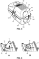
- FIG. 2 and 3 Further details of an embodiment of the cover box are shown on figure 2 and 3 , wherein the half-shells are two identical parts.
- the half-shells 11, 12 are able to be assembled together by cooperation of the latching means 16, 17 of the first half-shell 11 with the latching means 16, 17 of the second half-shell 12, the recess 15 of the first half-shell 11 then facing the recess 15 of the second half-shell 12 along the first direction Z when the half-shells 11, 12 are assembled together around an electrical connection, thus accommodating the screw head and the nut.
- the latching means 16, 17 here comprise a tab 16 and a notch 17, the tab 16, respectively the notch 17, of the first half-shell 11 being able to cooperate with the notch 17, respectively the tab 16, of the second half-shelf 12.
- the tab is an elongated tab 161 is elastically deformable and protrudes vertically along the first direction Z from each half-shell, for example from an outer wall, and comprises a free end.
- the free end may comprise a tooth 162 with a stopping surface 163.
- the elastic deformation of the tab allows the tooth 162 to be at least mobile along a transversal direction Y of the cover box 10.
- the notch 17 of a first half-shell 11 comprises a hollow sleeve 171 elongating vertically and comprises two openings at its ends configured to let all the way through the elongated tab 161 of the other half-shell.
- the tooth 162 comprises a biased surface 164 to force the elongated tab 161 out of a resting state when let through the sleeve 171 to a bending state, the sleeve then comprises a stopping edge 172 configured to block the stopping surface 163 of the tooth 162 when the tab comes back to its resting state, the cooperation between the stopping surface 163 and the stopping edge 172 is preventing the two half-shells 11, 12 from disassembling.
- the free end of the tab 16 comprises a slot 165 configured to accommodate the end of a tool that may be used to bend the tab back in its bending state to disassemble the two half-shells.
- Air inlets 20 here define a plurality of apertures to provide an airflow inside the interior volume V in order for example to cool down the electrical connection.
- air inlets 20 are elongated transversally, and theirwidth is inferior to 12,5 mm.
- the cover box 10 comprises a cable passage 14 delimiting an aperture comprising a first 141 and a second 142 part of aperture, the first half-shell 11 comprising the first part of aperture 141 and the second half-shell 12 comprising the second part of aperture 142.
- Each of the first 141 and second 142 part of aperture are able to let through an electric cable of the electrical connection 1 in order to avoid any interference when assembling both half-shells 11, 12 together.
- the first and second parts of aperture 141, 142 are obstructed by one detachable cover 143.
- each half-shell 11, 12 comprises half an obstruction tab 19 that is configured to obstruct at least part of a space between the cables that are let through by the parts of aperture 141, 142.
- Each half of obstruction tab here being a rigid part, protruding from the cover box in a non-perpendicular way with the cables, and each featuring two curved edge that match or roughly match the shape of the cables in order to perform their obstruction function.
- the tab may for example simply remain in place as represented on figure 2 or may be cut off.
- each half-shell 11, 12 comprises centering holes 113 and pins 114, the pins 114, respectively the centering holes 113, of the first half shell 11 being able to cooperate with the centering holes 113, respectively the pins 114, of the second half-shell when the half-shells 11, 12 are assembled together, the centering holes 113 and pins 114 being able to bring the latching means 16, 17 of the first half-shell 11 facing the latching means 16, 17 of the second half-shell 12.
- the pins are here designed with a cross shaped cross-section and comprise biased top guiding surfaces 115 defining slopes configured to guide the pins into the centering holes when approaching both half-shells 11, 12 together.
- the recesses are designed with a circular cross section. This preferred design allows not to interfere with a slight angular travel of the cover box once assembled around the electrical connection, because the circular inner wall simply rotate around the hexagonal shape of the nut or the screw head.
- the travel amplitude is shown on figure 5 and reaches +5/-5° in this embodiment.
- the cover box, and especially the recess is designed in 3 different sizes.
- one first size is adapted for a M6x20 nut and screw
- the other two sizes feature different width and cable passage 14 configurations and are adapted for M12x35 nut and screw.
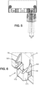
- the cover box 10 comprises two safety walls 18 elongating vertically on both sides of its latching means 16, 17.
- Each safety wall 18 comprises a first and a second part 181, 182, the first half-shell 11 comprising the first part 181, the second half-shell 12 comprising the second part 182, both parts of each safety wall 18 defining an extension of each other when the first and second half-shells 11, 12 are assembled.
- Figure 8 shows a possible embodiment in which two ring-tongues 3 at the end of two cables 4 are accommodated by the cover box 10.
- the electrical connection 1 also comprises here two wafers: one between the nut 51 and the first ring-tongue 3, the other between the screw head 52 and the second ring-tongue 3.
- the bar 2 is sandwiched between the two ring-tongues 3.
- This embodiment shows that the recesses 15 are dimensioned to perform their blocking function with different electrical connection 1 configuration.
- the present disclosure finds a particular application in any industrial field that may require the protection of electrical connections.
Landscapes
- Engineering & Computer Science (AREA)
- Architecture (AREA)
- Civil Engineering (AREA)
- Structural Engineering (AREA)
- Manufacturing & Machinery (AREA)
- Connection Or Junction Boxes (AREA)
Priority Applications (3)
| Application Number | Priority Date | Filing Date | Title |
|---|---|---|---|
| EP23306237.1A EP4496136A1 (de) | 2023-07-18 | 2023-07-18 | Abdeckkasten zum schutz einer elektrischen verbindung, anordnung und zugehöriges verfahren |
| US18/772,478 US20250030229A1 (en) | 2023-07-18 | 2024-07-15 | Cover box for protecting an electrical connection, assembly, and related method |
| CN202410949032.XA CN119340713A (zh) | 2023-07-18 | 2024-07-16 | 用于保护电连接件的盖盒、组件和相关方法 |
Applications Claiming Priority (1)
| Application Number | Priority Date | Filing Date | Title |
|---|---|---|---|
| EP23306237.1A EP4496136A1 (de) | 2023-07-18 | 2023-07-18 | Abdeckkasten zum schutz einer elektrischen verbindung, anordnung und zugehöriges verfahren |
Publications (1)
| Publication Number | Publication Date |
|---|---|
| EP4496136A1 true EP4496136A1 (de) | 2025-01-22 |
Family
ID=87553898
Family Applications (1)
| Application Number | Title | Priority Date | Filing Date |
|---|---|---|---|
| EP23306237.1A Pending EP4496136A1 (de) | 2023-07-18 | 2023-07-18 | Abdeckkasten zum schutz einer elektrischen verbindung, anordnung und zugehöriges verfahren |
Country Status (3)
| Country | Link |
|---|---|
| US (1) | US20250030229A1 (de) |
| EP (1) | EP4496136A1 (de) |
| CN (1) | CN119340713A (de) |
Citations (6)
| Publication number | Priority date | Publication date | Assignee | Title |
|---|---|---|---|---|
| WO1986001350A1 (en) * | 1984-08-20 | 1986-02-27 | Amp Incorporated | Rain tight junction box |
| US20050042933A1 (en) * | 2003-07-22 | 2005-02-24 | Abb Entrelec | Electrical connection device with protected contact |
| US6891104B2 (en) * | 2003-01-28 | 2005-05-10 | Thomas & Betts International, Inc. | Hinged weatherproof electrical box cover |
| US20050186846A1 (en) * | 2004-02-20 | 2005-08-25 | Jerry Wu | Electrical connector with non-conductive cover |
| US20160111824A1 (en) * | 2014-10-21 | 2016-04-21 | Tyco Electronics Corporation | Electrical connector having bussed ground contacts |
| US20220131355A1 (en) * | 2019-03-13 | 2022-04-28 | Commscope Technologies Llc | Re-enterable enclosure with environmental sealing |
Family Cites Families (3)
| Publication number | Priority date | Publication date | Assignee | Title |
|---|---|---|---|---|
| US6079673A (en) * | 1999-04-01 | 2000-06-27 | Andrew Corporation | Transmission line hanger |
| EP3557710A1 (de) * | 2018-04-20 | 2019-10-23 | CMP Products Limited | Vorrichtung zum halten von elektrischen kabeln |
| EP4167393B1 (de) * | 2021-10-13 | 2025-05-21 | Rosenberger Hochfrequenztechnik GmbH & Co. KG | Steckverbindergehäuse, sowie spritzgiessverfahren und spritzgiessvorrichtung zur herstellung eines steckverbindergehäuses |
-
2023
- 2023-07-18 EP EP23306237.1A patent/EP4496136A1/de active Pending
-
2024
- 2024-07-15 US US18/772,478 patent/US20250030229A1/en active Pending
- 2024-07-16 CN CN202410949032.XA patent/CN119340713A/zh active Pending
Patent Citations (6)
| Publication number | Priority date | Publication date | Assignee | Title |
|---|---|---|---|---|
| WO1986001350A1 (en) * | 1984-08-20 | 1986-02-27 | Amp Incorporated | Rain tight junction box |
| US6891104B2 (en) * | 2003-01-28 | 2005-05-10 | Thomas & Betts International, Inc. | Hinged weatherproof electrical box cover |
| US20050042933A1 (en) * | 2003-07-22 | 2005-02-24 | Abb Entrelec | Electrical connection device with protected contact |
| US20050186846A1 (en) * | 2004-02-20 | 2005-08-25 | Jerry Wu | Electrical connector with non-conductive cover |
| US20160111824A1 (en) * | 2014-10-21 | 2016-04-21 | Tyco Electronics Corporation | Electrical connector having bussed ground contacts |
| US20220131355A1 (en) * | 2019-03-13 | 2022-04-28 | Commscope Technologies Llc | Re-enterable enclosure with environmental sealing |
Also Published As
| Publication number | Publication date |
|---|---|
| US20250030229A1 (en) | 2025-01-23 |
| CN119340713A (zh) | 2025-01-21 |
Similar Documents
| Publication | Publication Date | Title |
|---|---|---|
| JP6457207B2 (ja) | 電気接続部を有するコンシールドドアヒンジ | |
| KR100838145B1 (ko) | 벽 아웃렛 | |
| WO1996028862A1 (en) | Cable retention and sealing device | |
| EP2914073B1 (de) | Elektronische Einheit | |
| KR102349749B1 (ko) | Bdu용 조립식 케이스 | |
| KR20160027026A (ko) | 전기 설비용 함체 | |
| CN106025661A (zh) | 贯通式连接器系统 | |
| KR20160025485A (ko) | 모터 및 이에 사용하는 암형 커넥터 | |
| US20250030229A1 (en) | Cover box for protecting an electrical connection, assembly, and related method | |
| JP6497508B2 (ja) | 防爆電気機器 | |
| JPH04210705A (ja) | 配電母線用保護ケーシング | |
| JP5346530B2 (ja) | コネクタモジュール用の保持フレーム | |
| JP5369586B2 (ja) | モジュラージャックの防塵構造 | |
| EP3766740A1 (de) | Schutzvorrichtung und kabelbaum | |
| JP2011120318A (ja) | ワイヤハーネス用のプロテクタ | |
| CN110574249B (zh) | 用于电气设备的设备壳体、带有这种设备壳体的系统和用于使用这种设备壳体的方法 | |
| KR101083393B1 (ko) | 버스 바 단부 연결부를 밀봉하기 위한 안전 플러그 | |
| EP4213320A1 (de) | Elektrisches montagegehäuse | |
| CZ68697A3 (en) | Wiring box for hollow walls | |
| US20210210898A1 (en) | Grommet and apparatus for aligning wire | |
| EP1187284B1 (de) | Elektrisches Verbindungsgehäuse | |
| JP5609395B2 (ja) | 筐体 | |
| JP4168266B2 (ja) | 閉鎖キャップ | |
| JP7215937B2 (ja) | 電線固定構造 | |
| CN116419832A (zh) | 分隔板以及线条构件的保护构件 |
Legal Events
| Date | Code | Title | Description |
|---|---|---|---|
| PUAI | Public reference made under article 153(3) epc to a published international application that has entered the european phase |
Free format text: ORIGINAL CODE: 0009012 |
|
| STAA | Information on the status of an ep patent application or granted ep patent |
Free format text: STATUS: THE APPLICATION HAS BEEN PUBLISHED |
|
| AK | Designated contracting states |
Kind code of ref document: A1 Designated state(s): AL AT BE BG CH CY CZ DE DK EE ES FI FR GB GR HR HU IE IS IT LI LT LU LV MC ME MK MT NL NO PL PT RO RS SE SI SK SM TR |
|
| STAA | Information on the status of an ep patent application or granted ep patent |
Free format text: STATUS: REQUEST FOR EXAMINATION WAS MADE |
|
| 17P | Request for examination filed |
Effective date: 20250618 |