EP4489423A2 - Kameramodul - Google Patents
Kameramodul Download PDFInfo
- Publication number
- EP4489423A2 EP4489423A2 EP24214874.0A EP24214874A EP4489423A2 EP 4489423 A2 EP4489423 A2 EP 4489423A2 EP 24214874 A EP24214874 A EP 24214874A EP 4489423 A2 EP4489423 A2 EP 4489423A2
- Authority
- EP
- European Patent Office
- Prior art keywords
- bracket
- round surface
- camera module
- disposed
- module according
- Prior art date
- Legal status (The legal status is an assumption and is not a legal conclusion. Google has not performed a legal analysis and makes no representation as to the accuracy of the status listed.)
- Pending
Links
Images



Classifications
-
- G—PHYSICS
- G03—PHOTOGRAPHY; CINEMATOGRAPHY; ANALOGOUS TECHNIQUES USING WAVES OTHER THAN OPTICAL WAVES; ELECTROGRAPHY; HOLOGRAPHY
- G03B—APPARATUS OR ARRANGEMENTS FOR TAKING PHOTOGRAPHS OR FOR PROJECTING OR VIEWING THEM; APPARATUS OR ARRANGEMENTS EMPLOYING ANALOGOUS TECHNIQUES USING WAVES OTHER THAN OPTICAL WAVES; ACCESSORIES THEREFOR
- G03B5/00—Adjustment of optical system relative to image or object surface other than for focusing
- G03B5/06—Swinging lens about normal to the optical axis
-
- H—ELECTRICITY
- H04—ELECTRIC COMMUNICATION TECHNIQUE
- H04N—PICTORIAL COMMUNICATION, e.g. TELEVISION
- H04N23/00—Cameras or camera modules comprising electronic image sensors; Control thereof
- H04N23/50—Constructional details
- H04N23/55—Optical parts specially adapted for electronic image sensors; Mounting thereof
-
- G—PHYSICS
- G02—OPTICS
- G02B—OPTICAL ELEMENTS, SYSTEMS OR APPARATUS
- G02B13/00—Optical objectives specially designed for the purposes specified below
- G02B13/001—Miniaturised objectives for electronic devices, e.g. portable telephones, webcams, PDAs, small digital cameras
-
- G—PHYSICS
- G02—OPTICS
- G02B—OPTICAL ELEMENTS, SYSTEMS OR APPARATUS
- G02B27/00—Optical systems or apparatus not provided for by any of the groups G02B1/00 - G02B26/00, G02B30/00
- G02B27/64—Imaging systems using optical elements for stabilisation of the lateral and angular position of the image
- G02B27/646—Imaging systems using optical elements for stabilisation of the lateral and angular position of the image compensating for small deviations, e.g. due to vibration or shake
-
- G—PHYSICS
- G02—OPTICS
- G02B—OPTICAL ELEMENTS, SYSTEMS OR APPARATUS
- G02B7/00—Mountings, adjusting means, or light-tight connections, for optical elements
- G02B7/02—Mountings, adjusting means, or light-tight connections, for optical elements for lenses
- G02B7/023—Mountings, adjusting means, or light-tight connections, for optical elements for lenses permitting adjustment
-
- G—PHYSICS
- G02—OPTICS
- G02B—OPTICAL ELEMENTS, SYSTEMS OR APPARATUS
- G02B7/00—Mountings, adjusting means, or light-tight connections, for optical elements
- G02B7/02—Mountings, adjusting means, or light-tight connections, for optical elements for lenses
- G02B7/04—Mountings, adjusting means, or light-tight connections, for optical elements for lenses with mechanism for focusing or varying magnification
- G02B7/08—Mountings, adjusting means, or light-tight connections, for optical elements for lenses with mechanism for focusing or varying magnification adapted to co-operate with a remote control mechanism
-
- G—PHYSICS
- G03—PHOTOGRAPHY; CINEMATOGRAPHY; ANALOGOUS TECHNIQUES USING WAVES OTHER THAN OPTICAL WAVES; ELECTROGRAPHY; HOLOGRAPHY
- G03B—APPARATUS OR ARRANGEMENTS FOR TAKING PHOTOGRAPHS OR FOR PROJECTING OR VIEWING THEM; APPARATUS OR ARRANGEMENTS EMPLOYING ANALOGOUS TECHNIQUES USING WAVES OTHER THAN OPTICAL WAVES; ACCESSORIES THEREFOR
- G03B17/00—Details of cameras or camera bodies; Accessories therefor
- G03B17/02—Bodies
- G03B17/12—Bodies with means for supporting objectives, supplementary lenses, filters, masks, or turrets
-
- G—PHYSICS
- G03—PHOTOGRAPHY; CINEMATOGRAPHY; ANALOGOUS TECHNIQUES USING WAVES OTHER THAN OPTICAL WAVES; ELECTROGRAPHY; HOLOGRAPHY
- G03B—APPARATUS OR ARRANGEMENTS FOR TAKING PHOTOGRAPHS OR FOR PROJECTING OR VIEWING THEM; APPARATUS OR ARRANGEMENTS EMPLOYING ANALOGOUS TECHNIQUES USING WAVES OTHER THAN OPTICAL WAVES; ACCESSORIES THEREFOR
- G03B3/00—Focusing arrangements of general interest for cameras, projectors or printers
- G03B3/10—Power-operated focusing
-
- G—PHYSICS
- G03—PHOTOGRAPHY; CINEMATOGRAPHY; ANALOGOUS TECHNIQUES USING WAVES OTHER THAN OPTICAL WAVES; ELECTROGRAPHY; HOLOGRAPHY
- G03B—APPARATUS OR ARRANGEMENTS FOR TAKING PHOTOGRAPHS OR FOR PROJECTING OR VIEWING THEM; APPARATUS OR ARRANGEMENTS EMPLOYING ANALOGOUS TECHNIQUES USING WAVES OTHER THAN OPTICAL WAVES; ACCESSORIES THEREFOR
- G03B30/00—Camera modules comprising integrated lens units and imaging units, specially adapted for being embedded in other devices, e.g. mobile phones or vehicles
-
- G—PHYSICS
- G03—PHOTOGRAPHY; CINEMATOGRAPHY; ANALOGOUS TECHNIQUES USING WAVES OTHER THAN OPTICAL WAVES; ELECTROGRAPHY; HOLOGRAPHY
- G03B—APPARATUS OR ARRANGEMENTS FOR TAKING PHOTOGRAPHS OR FOR PROJECTING OR VIEWING THEM; APPARATUS OR ARRANGEMENTS EMPLOYING ANALOGOUS TECHNIQUES USING WAVES OTHER THAN OPTICAL WAVES; ACCESSORIES THEREFOR
- G03B5/00—Adjustment of optical system relative to image or object surface other than for focusing
-
- G—PHYSICS
- G03—PHOTOGRAPHY; CINEMATOGRAPHY; ANALOGOUS TECHNIQUES USING WAVES OTHER THAN OPTICAL WAVES; ELECTROGRAPHY; HOLOGRAPHY
- G03B—APPARATUS OR ARRANGEMENTS FOR TAKING PHOTOGRAPHS OR FOR PROJECTING OR VIEWING THEM; APPARATUS OR ARRANGEMENTS EMPLOYING ANALOGOUS TECHNIQUES USING WAVES OTHER THAN OPTICAL WAVES; ACCESSORIES THEREFOR
- G03B5/00—Adjustment of optical system relative to image or object surface other than for focusing
- G03B5/04—Vertical adjustment of lens; Rising fronts
-
- H—ELECTRICITY
- H04—ELECTRIC COMMUNICATION TECHNIQUE
- H04N—PICTORIAL COMMUNICATION, e.g. TELEVISION
- H04N23/00—Cameras or camera modules comprising electronic image sensors; Control thereof
- H04N23/50—Constructional details
-
- H—ELECTRICITY
- H04—ELECTRIC COMMUNICATION TECHNIQUE
- H04N—PICTORIAL COMMUNICATION, e.g. TELEVISION
- H04N23/00—Cameras or camera modules comprising electronic image sensors; Control thereof
- H04N23/50—Constructional details
- H04N23/54—Mounting of pick-up tubes, electronic image sensors, deviation or focusing coils
-
- H—ELECTRICITY
- H04—ELECTRIC COMMUNICATION TECHNIQUE
- H04N—PICTORIAL COMMUNICATION, e.g. TELEVISION
- H04N23/00—Cameras or camera modules comprising electronic image sensors; Control thereof
- H04N23/57—Mechanical or electrical details of cameras or camera modules specially adapted for being embedded in other devices
-
- H—ELECTRICITY
- H04—ELECTRIC COMMUNICATION TECHNIQUE
- H04N—PICTORIAL COMMUNICATION, e.g. TELEVISION
- H04N23/00—Cameras or camera modules comprising electronic image sensors; Control thereof
- H04N23/60—Control of cameras or camera modules
- H04N23/68—Control of cameras or camera modules for stable pick-up of the scene, e.g. compensating for camera body vibrations
- H04N23/681—Motion detection
- H04N23/6812—Motion detection based on additional sensors, e.g. acceleration sensors
-
- H—ELECTRICITY
- H04—ELECTRIC COMMUNICATION TECHNIQUE
- H04N—PICTORIAL COMMUNICATION, e.g. TELEVISION
- H04N23/00—Cameras or camera modules comprising electronic image sensors; Control thereof
- H04N23/60—Control of cameras or camera modules
- H04N23/68—Control of cameras or camera modules for stable pick-up of the scene, e.g. compensating for camera body vibrations
- H04N23/682—Vibration or motion blur correction
- H04N23/685—Vibration or motion blur correction performed by mechanical compensation
- H04N23/687—Vibration or motion blur correction performed by mechanical compensation by shifting the lens or sensor position
-
- G—PHYSICS
- G03—PHOTOGRAPHY; CINEMATOGRAPHY; ANALOGOUS TECHNIQUES USING WAVES OTHER THAN OPTICAL WAVES; ELECTROGRAPHY; HOLOGRAPHY
- G03B—APPARATUS OR ARRANGEMENTS FOR TAKING PHOTOGRAPHS OR FOR PROJECTING OR VIEWING THEM; APPARATUS OR ARRANGEMENTS EMPLOYING ANALOGOUS TECHNIQUES USING WAVES OTHER THAN OPTICAL WAVES; ACCESSORIES THEREFOR
- G03B2205/00—Adjustment of optical system relative to image or object surface other than for focusing
- G03B2205/0007—Movement of one or more optical elements for control of motion blur
-
- G—PHYSICS
- G03—PHOTOGRAPHY; CINEMATOGRAPHY; ANALOGOUS TECHNIQUES USING WAVES OTHER THAN OPTICAL WAVES; ELECTROGRAPHY; HOLOGRAPHY
- G03B—APPARATUS OR ARRANGEMENTS FOR TAKING PHOTOGRAPHS OR FOR PROJECTING OR VIEWING THEM; APPARATUS OR ARRANGEMENTS EMPLOYING ANALOGOUS TECHNIQUES USING WAVES OTHER THAN OPTICAL WAVES; ACCESSORIES THEREFOR
- G03B2205/00—Adjustment of optical system relative to image or object surface other than for focusing
- G03B2205/0007—Movement of one or more optical elements for control of motion blur
- G03B2205/0023—Movement of one or more optical elements for control of motion blur by tilting or inclining one or more optical elements with respect to the optical axis
-
- G—PHYSICS
- G03—PHOTOGRAPHY; CINEMATOGRAPHY; ANALOGOUS TECHNIQUES USING WAVES OTHER THAN OPTICAL WAVES; ELECTROGRAPHY; HOLOGRAPHY
- G03B—APPARATUS OR ARRANGEMENTS FOR TAKING PHOTOGRAPHS OR FOR PROJECTING OR VIEWING THEM; APPARATUS OR ARRANGEMENTS EMPLOYING ANALOGOUS TECHNIQUES USING WAVES OTHER THAN OPTICAL WAVES; ACCESSORIES THEREFOR
- G03B2205/00—Adjustment of optical system relative to image or object surface other than for focusing
- G03B2205/0053—Driving means for the movement of one or more optical element
- G03B2205/0069—Driving means for the movement of one or more optical element using electromagnetic actuators, e.g. voice coils
Definitions
- the embodiment relates to a camera actuator and a camera module including the same.
- the camera module performs a function of photographing a subject and storing it as an image or video, and is mounted on a mobile terminal such as a mobile phone, a laptop computer, a drone, or a vehicle, etc.
- portable devices such as smartphones, tablet PCs, and laptops have built-in micro camera modules, and these camera modules automatically adjust the distance between the image sensor and the lens to align the focal length of the lens such that Auto-Focus (AF) function can be performed.
- AF Auto-Focus
- a recent camera module can perform a zooming function of zooming up or zooming out by increasing or decreasing the magnification of a distant subject through a zoom lens.
- IS image stabilization
- OIS Optical Image Stabilizer
- the OIS technology is a technology that corrects motion by changing the path of light
- an anti-shake technology using an image sensor is a technology that corrects movement in a mechanical and electronic manner, and the OIS technology is more widely adopted.
- the image sensor has a higher resolution as it goes to a higher pixel, so that the size of the pixel decreases.
- the pixel becomes smaller, the amount of light received at the same time decreases. Therefore, in a dark environment, the higher the pixel camera, the more severe the blurring of the image due to hand shake appears as the shutter speed decreases.
- the OIS function has recently been essentially adopted.
- the OIS technology is a method of correcting the image quality by correcting the optical path by moving the lens or image sensor of the camera.
- the OIS technology detects camera movement with a gyro sensor. Based on this, the distance the lens or image sensor should move is calculated.
- the OIS correction method includes a lens shift method and a lens tilt method.
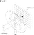
- FIG. 1A is a conceptual diagram of an OIS through a lens movement method in a camera module of a related art
- FIG. 1B is a conceptual diagram of an OIS through a lens tilt method in a camera module of the related art.
- the optical axis which is the reference of the point with the spatial resolution (SFR) value in the image sensor, is repeatedly moved from Z1 to Z2 according to the movement of the lens. Distortion of the video is severe, and the situation is causing rumbling to users, etc., and this problem is also occurring in the sensor shift method.
- the OIS technology of the related art is complicated in structure because a mechanical actuator is required for lens movement, and a driving element or a gyro sensor must be mounted, so there is a limitation in implementing a micro camera module.
- the embodiment is to provide a camera module and an actuator of the camera module capable of providing an excellent OIS function without distortion of an image even during video recording.
- the embodiment is to solve the above-described technical problem and at the same time provide a micro camera module.
- the camera module includes a lens module, a first bracket including a first round surface and moving coupled with the lens module, a second bracket including a second round surface corresponding to the first round surface, a ball bearing disposed between the first round surface of the first bracket and the second round surface of the second bracket, and a driving unit disposed between the lens module and the second bracket.
- the width and height of the second round surface of the second bracket may be greater than the width and height of the first round surface of the first bracket.
- the camera module includes a lens module, a first bracket including a first round surface and moving coupled with the lens module, a second bracket including a second round surface corresponding to the first round surface, a ball bearing disposed between the first round surface of the first bracket and the second round surface of the second bracket, and a driving unit disposed between the lens module and the second bracket.
- the first round surface of the first bracket may include at least two first unit round surfaces, and the two first unit round surfaces may be disposed opposite to each other around the lens module.
- the second round surface of the second bracket may include at least two second unit round surfaces, and each of the at least two second unit round surfaces may be disposed to correspond to each of the at least two first unit round surfaces.
- the camera module includes a lens module, a first bracket including a first round surface and moving coupled with the lens module to move, a second bracket including a second round surface corresponding to the first round surface, a ball bearing disposed between the first round surface of the first bracket and the second round surface of the second bracket, and a driving unit disposed between the lens module and the second bracket.
- the lens module may rotate along the second round surface with respect to the optical axis, and the lens module may be driven vertically with respect to the optical axis along the second round surface.
- the ball bearing may move along the first round surface and the second round surface so that the lens module rotates with respect to the optical axis.
- the ball bearing may move along the first round surface and the second round surface so that the lens module is tilted based on an imaginary plane perpendicular to the optical axis.
- the first round surface may be disposed on an outer surface of the first bracket.
- the second round surface may be disposed on an inner surface of the second bracket.
- An upper end of the first bracket may be disposed lower than an upper end of the second bracket.
- the first bracket includes a first recess region on an inner surface thereof and disposed at a position corresponding to the first round surface
- the second bracket includes a second recess region on an outer surface thereof and disposed at a position corresponding to the second round surface.
- the embodiment further includes a circuit board disposed under the second bracket and controlling the driving unit, the circuit board including a rigid circuit board and a flexible circuit board, and a part of the flexible circuit board may be disposed in the second recess region of the second bracket.
- the first bracket may include a ball receiving part in which the ball bearing is disposed, and the ball receiving part may be disposed at a position corresponding to the first recess region.
- the driving unit may include a first driving unit generating electromagnetic force in an optical axis direction and a second driving unit generating electromagnetic force in a direction perpendicular to the optical axis direction.
- the first driving unit includes a first coil unit coupled to the first bracket and a first magnet unit coupled to the second bracket
- the second driving unit includes a second coil unit coupled to the first bracket and include a second magnet portion coupled to the second bracket.
- the first bracket may include a ball receiving part in which the ball bearing is disposed.
- the camera module may include a lens module; a first bracket supporting and driving the lens module; a second bracket accommodating the first bracket; a ball disposed between the first bracket and the second bracket; and a driving unit for driving the lens module.
- the driving apparatus of the camera module includes: a first bracket supporting and driving a predetermined lens module; a second bracket accommodating the first bracket; a driving unit driving the first bracket; and a circuit board for controlling the driving unit.
- the embodiment may provide a camera module capable of providing an excellent OIS function without distortion of an image even when capturing a video and an actuator for the camera module.
- the embodiment has a technical effect capable of providing a micro-camera module at the same time as the technical effect described above.
- the embodiment is a method of moving the entire module including the lens and the image sensor. Compared to the lens moving method, the embodiment has a technical effect in that the correction range is wider, and since the optical axis of the lens and the axis of the image sensor are not twisted, it is possible to minimize image deformation.
- the upper (top) or lower (under) includes both elements in direct contact with each other or in which one or more other elements indirectly formed between the two elements.
- the meaning of not only an upward direction but also a downward direction based on one element may be included.
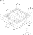
- FIG. 2A is a perspective view showing the camera module 201 of the embodiment
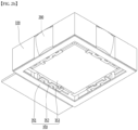
- FIG. 2B is a bottom perspective view of the camera module 201 of the embodiment
- FIG. 3 is an exploded perspective view of the camera module 201 of the embodiment shown in FIG. 2A .
- the movement of the camera module may include a linear movement moving along an axis and a rotational movement rotating around the axis in a big view.
- the camera module according to the embodiment may be applied to both the front or rear, the bottom and the rear of the mobile phone.
- FIG. 3 is an exploded perspective view of the camera module 201 of the embodiment shown in FIG. 2A .
- the camera module 201 of the embodiment may include a lens module 200, a first bracket 310, a ball bearing 316, a second bracket 320, a driving unit 340, and a circuit board 350.
- the camera module 201 of the embodiment includes a circuit board 350, an image sensor (not shown) disposed on the circuit board 350, and a lens unit 220 disposed on the image sensor and a housing 210 accommodating the lens unit 220.
- the image sensor, the lens unit 220 and the housing 210 may be referred to as a lens module 200.
- the camera module 201 of the embodiment may include a separate AF driver, for example, VCM, MEMS, piezo, liquid lens, or the like.
- the image sensor substrate may be integrally formed with the circuit board 350 or may be formed separately.
- the substrate of the image sensor when it is formed separately from the circuit board 350, it may be electrically connected to each other.
- the camera module 201 of the embodiment includes a gyro sensor (not shown) disposed on the circuit board 350 to detect motion, and a module driving unit that drives the lens module 200 according to input/output signals from the gyro sensor and a driving circuit element (not shown) for controlling the module driver 300.
- a gyro sensor (not shown) disposed on the circuit board 350 to detect motion
- a module driving unit that drives the lens module 200 according to input/output signals from the gyro sensor and a driving circuit element (not shown) for controlling the module driver 300.
- the module driving unit 300 includes a first bracket 310 supporting and driving the lens module 200, and a second bracket 320 accommodating the first bracket 310 and a driving unit 340 to drive the first bracket 310.
- the first bracket 310 supports the lens module 200 and a configuration of the module driving unit 300, for example, a coil or the like, and performs Pitch, Yaw, and Roll operations together with the AF function of the lens module 200.
- the second bracket 320 may be a fixed part for accommodating the first bracket 310 but performing pitch, yaw, and roll operations of the lens module 200 through the first bracket 310.
- the second bracket 320 may be fixed to the mobile phone, and the first bracket 310 may be attached to the camera module to guide the operation of the camera module.
- the first bracket 310 and the second bracket 320 may be connected by a predetermined spring 400, through which the initial position of the lens module 200 may be set.
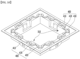
- the spring 400 may include an outer support part 410, a spring part 420, and an inner support part 430.
- the outer support part 410 may be supported or fixed to the second bracket 320, and the inner support part 430 may be supported or fixed to the first bracket 310.
- an initial position of the lens module 200 may be set between the first bracket 310 and the second bracket 320 by a predetermined magnetic force.
- FIG. 10 is an exemplary view of coupling the spring 400 and the first bracket 310 in the embodiment.
- the inner support part 430 of the spring 400 may be supported or fixed to the first bracket 310.
- the camera module 201 of the embodiment includes a shield can (not shown) on the outer surface of the lens module 200, the first bracket 310, and the second bracket 320.
- the shield can may be referred to as a cover housing.
- the shield can is formed of a metal material such as steel (SUS), and may shield electromagnetic waves flowing into and out of the camera module, and also prevent foreign matter from entering the camera module.
- SUS steel
- the lens unit 220 may be equipped with a predetermined barrel (not shown) and a lens (not shown).
- the lens may include a single lens or a plurality of lenses.
- the lens may comprise a liquid lens.
- an actuator capable of driving the lens unit 220 may be disposed on the housing 210.
- the actuator may be a voice coil motor, a micro actuator, a silicon actuator, a shape memory alloy (SAM), etc., and may be applied in various ways such as an electrostatic method, a thermal method, a bimorph method, an electrostatic force method, a piezo actuator, etc.
- the actuator may support the lens unit 220 and perform an auto-focusing function by moving the lens up and down in response to a control signal from a predetermined control unit.
- the lens module 200 may include a voice coil motor, a MEMS actuator, and a piezo actuator to move the lens up and down, and other embodiments may include a liquid lens in addition to the lens without a separate actuator.
- the voice coil motor moves the entire lens of the lens module up and down
- the MEMS and piezo actuators move some lenses of the lens module up and down
- the liquid lens adjusts the focus by changing the curvature of the interface between the two liquids.
- the gyro sensor may employ a two-axis gyro sensor that detects two rotational motion amounts of pitch and yaw representing a large motion in a two-dimensional image frame, and for more accurate camera shake correction. It is also possible to employ a three-axis gyro sensor that detects the amount of movement of the pitch, yaw and roll. Movements corresponding to the pitch, yaw, and roll detected by the gyro sensor may be converted into an appropriate physical quantity according to a camera shake correction method and a correction direction.
- the circuit board 350 may include any substrate having a wiring pattern that can be electrically connected, such as a rigid printed circuit board (rigid PCB), a flexible printed circuit board (flexible PCB), and a rigid flexible printed circuit board (rigid-flexible PCB).
- a rigid printed circuit board rigid PCB
- flexible PCB flexible printed circuit board
- rigid-flexible PCB rigid flexible printed circuit board
- the circuit board 350 may include a first circuit board 351, a second circuit board 352, and a third circuit board 353.
- the first circuit board 351 may be a rigid printed circuit board (rigid PCB)
- the second circuit board 352 may be a flexible printed circuit board (flexible PCB) or a rigid-flexible PCB.
- the third circuit board 353 may be a rigid circuit board, but is not limited thereto.
- the second circuit board 352 may be arranged in a curved shape in the form of a flexible circuit board.
- the first circuit board 351 may be fixed to the second bracket 320, and the third circuit board 353 may be electrically connected to the lens module 200, but is not limited thereto.
- the second bracket 320 may include a plurality of second recesses 320R2.
- the second bracket 320 may have a second recess 320R2 on each of the four sides.
- the second circuit board 352 may be separately disposed in the second recess 320R2 of the second bracket 320.
- the second circuit board 352 may be separately disposed in the second recess 320R2 of the second bracket 320.
- the second circuit board 352 is disposed in the second recess 320R2 of the second bracket 320, interference between the second circuit board 352 and the driver 240 can be prevented such that the electrical reliability can be also improved.
- FIG. 4A is a cross-sectional perspective view of the camera module 201 along line A1-A1' according to the embodiment shown in FIG. 2A
- FIG. 4B is a cross-sectional view taken along line A-A1' of the camera module 201 according to the embodiment shown in FIG. 2A
- FIG. 5 is a partially enlarged view of the first area B1 of the camera module according to the embodiment shown in FIG. 4B .
- the first bracket 310 may include a plurality of first recesses 310R1.
- the first bracket 310 may have a first recess 310R1 region on each side of four surfaces.
- the first bracket 310 can be precisely injected by having the first recess 310R1 region, and can contribute to miniaturization such that the operation speed can be improved according to weight reduction.
- a protrusion may be formed at a position corresponding to the ball bearing 316 in the first recess region 310R1.
- the second bracket 320 may also include a plurality of second recesses 320R2.
- the second bracket 320 may have a second recess 320R2 on each of the four sides.
- first bracket 310 may include a plurality of ball receiving parts 312 in which the ball bearings 316 are disposed.
- the first bracket 310 may have a ball receiving part 312 on each of the four sides.
- the upper and lower first width W1 of the ball receiving part 312 of the first bracket 310 may be larger than the diameter D1 of the ball.
- the first width W1 may be 1.1 to 1.5 times the size of the ball diameter D1. Accordingly, it is possible to secure a moving space of the lens module while Yaw and Pith driving.
- the upper and lower first width W1 of the ball receiving part 312 of the first bracket 310 may be 1.2 times the diameter of the ball D1, but are not limited thereto.
- the ball diameter D1 may be about 0.4mm to 0.8mm, but is not limited thereto. In the embodiment, the ball diameter D1 may be 0.6mm, but is not limited thereto.
- the first bracket 310 includes a first round surface 310S having a curved side surface
- the second bracket 320 may include a second round surface (320S) having a curved surface corresponding to the first round surface 310S.
- the curvature of the first round surface 310S may be the same as the curvature of the second round surface 320S, but is not limited thereto.
- the first round surface 310S and the second round surface 320S which are curved surfaces, respectively have the same curvature, so that when the yaw, pitch or roll is driven, it can be driven without interference by maintaining a distance from each other.
- the first round surface 310S may be disposed on an outer side end surface of the first bracket 310, and the second round surface 320S may be disposed on an inner side end surface of the second bracket 320.
- the first bracket 310 and the second bracket 320 are provided with a first round surface 310S and a second round surface 320S, which are curved surfaces, respectively, so that the driving unit 340 can smoothly perform roll, yaw or pitch driving of the lens module 200.
- the upper end of the first bracket 310 is disposed lower than the upper end of the second bracket 320 so that the roll driving of the lens module 200 can be smoothly performed.
- the lower end of the first bracket 310 is disposed higher than the lower end of the second bracket 320 so that at least one of the roll, yaw, and pitch of the lens module 200 can be smoothly performed.
- a lower end of the second bracket 320 may be provided with a stopper part 320B to function as a stopper for stopping the movement of the first bracket 310.
- FIG. 6A is a cross-sectional view along line A2-A2' of the camera module according to the embodiment shown in FIG. 2A
- FIG. 6B is a partially enlarged view of a second area B2 of the camera module according to the embodiment shown in FIG. 6A
- FIG. 6C is a partially enlarged view of the third area B3 of the camera module according to the embodiment illustrated in FIG. 6A .
- the first bracket 310 may include a first round surface 310S having a curved side surface.
- the first round surface 310S of the first bracket 310 includes at least two first unit round surfaces 310SR1, 310SR2, 310SR3, 310SR4, and the two first unit round surfaces 310SR1, 310SR2, 310SR3, 310SR4 may be disposed opposite to each other around the lens module 200.
- the first bracket 310 includes the first-first to first-fourth unit round surfaces 310SR1, 310SR2, 310SR3, 310SR4, and the first-first and first-second unit round surfaces 310SR1 and 310SR2 may be disposed opposite each other around the lens module 200.
- the first-third and first-fourth unit round surfaces 310SR3 and 310SR4 may be disposed opposite to each other around the lens module 200.
- the first unit round surface may be referred to as an inclined side pillar.
- the first bracket 310 of the embodiment may include a plurality of inclined side pillars and vertical side pillars disposed between each inclined side pillar.
- the first bracket 310 may include a first-first inclined side pillars to a first-fourth inclined side pillars 310SR1, 310SR2, 310SR3, 310SR4 and a first-first to a first-fourth vertical side pillars 310SVR1, 310SV2, 310SV3, and 310SV4 disposed between each of the inclined side pillars on the side of four surfaces.
- the first-first inclined side pillar 310SR1 and the first-second inclined side pillar 310SR2 may be arranged to be symmetrical to each other, and the first-third inclined side pillar 310SR3 and the first-fourth inclined side pillar 310SR4 may also be arranged to be symmetrical to each other.
- the second bracket 320 may also include a second round surface 320S having a curved side surface.
- the second round surface 320S of the second bracket 320 includes at least two second unit round surfaces 320SR1, 320SR2, 320SR3, and 320SR4, and the two second unit round surfaces 320SR1, 320SR2, 320SR3, and 320SR4 may be disposed opposite to each other around the lens module 200.
- the second bracket 320 includes second-first to second-fourth unit round surfaces 320SR1, 320SR2, 320SR3, and 320SR4, and the second-first to second-second unit round surfaces 320SR1 and 320SR2 may be disposed opposite to each other around the lens module 200.
- the second-third to second-fourth unit round surfaces 320SR3 and 320SR4 may be disposed opposite to each other around the lens module 200.
- the second unit round surface may be referred to as an inclined side pillar.
- the second round surface 320S of the second bracket 320 may include a second-first inclined side pillars to a second-fourth inclined side pillars 320SR1, 320SR2, 320SR3, and 320SR4, and may include vertical side pillars 320SV1, 320SV2, 320SV3, and 320SV4 disposed between the inclined side pillars respectively.
- the second-first inclined side pillar 320SR1 and the second-second inclined side pillar 320SR2 may be arranged to be symmetrical to each other, and the second-third inclined side pillar 320SR3 and the second-fourth inclined side pillar 320SR4 may also be arranged to be symmetrical to each other.
- the ball receiving part 312 may be disposed between the first round surface 310S of the first bracket 310 and the second round surface 320S of the second bracket 320.
- the ball receiving part 312 may be disposed between a first-first unit round surface to a first-fourth unit round surface 310SR1, 310SR2, 310SR3, 310SR4, and a second-first unit round surface to second-fourth unit round surfaces 320SR1, 320SR2, 320SR3, and 320SR4, respectively corresponding to each other.
- the first bracket 310 can include a first-first unit round surface to a first-fourth unit round surface 310SR1, 310SR2, 310SR3, 310SR4, but may not include vertical side pillars 310SV1, 310SV2, 310SV3, 310SV4.
- the first bracket 310 may have a structure in which the first-first unit round surfaces to the first-fourth unit round surfaces 310SR1, 310SR2, 310SR3, and 310SR4 connected to each other.
- the housing of the lens module and the first-first unit round surface to the first-fourth unit round surface 310SR1, 310SR2, 310SR3, 310SR4 may be integrally formed, but are not limited thereto.
- FIG. 6B is a partially enlarged view of the second area B2 of the camera module according to the embodiment illustrated in FIG. 6A .
- the ball receiving part 312 provided in the first bracket 310 may have a V-shaped shape.
- the ball bearing 316 may contact the first bracket 310 and the second bracket 320 in three points as a whole.
- the ball receiving part 312 provided on the first bracket 310 includes a first inclined surface 312S1, a second inclined surface 312S2, and a bottom surface 312B, thereby it can form a V-shaped rail.
- the ball receiving part 312 of the first bracket 310 may have a V-shaped rail formed in the z-axis direction.
- the ball bearing 316 may contact the first bracket 310 at two points and contact the second bracket 320 at one point such that three point contact can be made.
- the horizontal cross section of the ball receiving part 312 may have a circular shape.
- the first-first unit round surface 310SR1 of the first bracket 310 may have a round protrusion 310SP in an opposite area corresponding to the ball receiving part 312.
- the round surfaces 310SR2, 310SR3, and 310SR4 of the first-second, first-third, and first-fourth units may also have a round protrusion 310SP in an opposite region corresponding to the ball receiving part 312.
- FIG. 6C is a partially enlarged view of the third area B3 of the camera module according to the embodiment illustrated in FIG. 6A .
- the first bracket 310 may include a first-second recess 310R2 between the first-first unit round surface 310SR1 and the first-first vertical column 310SV1.
- the second bracket 320 may include a second-first protrusion 320SP1 between the second-first unit round surface 320SR1 and the second-first vertical pillar 320SV1.
- the second-first protrusion 320SP1 may allow the first bracket 310 to be disposed in the first-second recess 310R2 so that Yaw, pitch, or roll driving can be smoothly performed.
- the second-first protrusion 320SP1 may function as a stopper when the first bracket 310 is rolled.
- FIG. 7 is a perspective view of the first bracket 310 and the driving unit 340 in the camera module according to the embodiment shown in FIG. 2A
- FIGS. 8A and 8B are exemplary views of driving the camera module according to the embodiment.
- the driving unit 340 may include a first driving unit 341 and a second driving unit 342.
- the driving unit 340 may be coupled to the lens module, but is not limited thereto.
- the first driving unit 341 may include a first magnet 341m and a first coil unit 341c to induce a force F1 in a first direction.
- the first driving unit 341 may include a first magnet 341m and a donut-shaped first coil unit 341c to induce a first force F1 in the z-axis direction.
- the first magnet 341m is a magnet in which an n-pole and an s-pole are disposed in a vertical direction, and may induce an electromagnetic force in a vertical direction.
- the second driving unit 342 may include a second magnet 342m and a second coil unit 342c to induce a force F2 in the second direction.
- the second magnet 342m may be seated so that the n-pole or the s-pole horizontally faces the second coil unit 342c to induce a force F2 in the horizontal direction (Y-axis direction).
- the second driving unit 342 may include a second magnet 342m and a donut-shaped second coil unit 342c to induce a second force F2 in the y-axis direction.
- a first yoke 344 may be disposed between the driving unit 340 and the first bracket 310, and the first yoke 344 functions as a back yoke to make the magnetic flux uniform and can prevent it from leaking externally.
- a second yoke (not shown) made of iron may be further provided between the second magnet 342m and the second coil part 342c.
- a magnetic member such as a second yoke may be inserted and disposed inside the second coil unit 342c.
- a second yoke may be provided at the center of the second coil part 342c, and a solenoid may be implemented with the yoke and the second coil part 342c.
- the first and second coils 341c and 342c are attached to the first bracket 310, and the first and second magnets 341m and 342m are separated from the coils.
- a structure in which the first, second magnets 341m and 342m are attached to the first bracket 310 and the coils are separated from magnets may also be possible.
- roll driving may be possible according to the embodiment.
- the second-first protrusion 320SP1 may allow the first bracket 310 to be disposed in the first-second recess 310R2 so that the roll driving can proceed smoothly.
- the first bracket 310 may function as a roll driving stopper.
- the first bracket 310 includes a first round surface 310S having a curved side surface.
- the second bracket 320 is attached to the first round surface 310S and may include a second round surface 320S having a corresponding curved surface.
- the curvature of the first round surface 310S may be the same as the curvature of the second round surface 320S, but is not limited thereto.
- the first round surface 310S and the second round surface 320S which are curved surfaces, respectively have the same curvature, so that when yaw, pitch or roll is driven, it can be driven without interference by maintaining a distance from each other.
- the first round surface 310S may be disposed on an outer side end surface of the first bracket 310, and the second round surface 320S may be disposed on an inner side end surface of the second bracket 320.
- the first bracket 310 and the second bracket 320 are provided with a first round surface 310S and a second round surface 320S, which are curved surfaces, respectively, so that the driving unit 340 can provide a smooth driving of the lens module 200 for roll, yaw or pitch.
- the upper end of the first bracket 310 is disposed lower than the upper end of the second bracket 320 so that the roll driving of the lens module 200 can be smoothly performed.
- the lower end of the first bracket 310 is disposed higher than the lower end of the second bracket 320 so that at least one of the roll, yaw, and pitch of the lens module 200 can be smoothly performed.
- a lower end of the second bracket 320 may be provided with a stopper part 320B to function as a stopper for stopping the movement of the first bracket 310.
- a rotation angle of about 0.8 to 2.0° (including a rotation angle of 1°) can be secured by Roll driving or Yaw/Pitch tilting driving, thereby performing an effective OIS function.
- the embodiment may provide a camera module capable of providing an excellent OIS function without distortion of image quality even when photographing a video, and an actuator for the camera module.
- the embodiment has a technical effect capable of providing a micro-camera module at the same time as the technical effect described above.
- the camera module of the embodiment may include a separate AF driver, for example, VCM, MEMS, piezo, liquid lens, and the like.
- the image sensor substrate may be formed integrally with the circuit board or may be formed separately.
- the camera module of the embodiment includes a gyro sensor (not shown) disposed on the circuit board to detect movement, a module driver for driving the lens module according to input/output signals from the gyro sensor, and a driving circuit for controlling the module driver including an element (not shown).
- the lens module may include a voice coil motor, a MEMS actuator, and a piezo actuator to move the lens up and down, and other embodiments may include a liquid lens in addition to the lens without a separate actuator.
- a camera module comprising:
- the camera module according item 1 wherein the ball bearing moves along the first round surface and the second round surface so that the lens module rotates based on the optical axis.
- the camera module according item 1 wherein the ball bearing is moved along the first round surface and the second round surface so that the lens module is tilted with respect to a virtual plane perpendicular to the optical axis.
- the camera module according item 1 wherein the first round surface is disposed on an outer surface of the first bracket, and the second round surface is disposed on an inner surface of the second bracket.
- the camera module according item 1 wherein the first bracket comprises a first recess region formed on an inner surface of the first bracket and disposed at a position corresponding to the first round surface.
- the camera module according item 1 wherein the second bracket comprises a second recess region formed on an outer surface of the second bracket and disposed at a position corresponding to the second round surface.
- the camera module according to item 10 wherein the first-first inclined side pillar and the first-second inclined side pillar are arranged to be symmetrical to each other, and the first-third inclined side pillar and the first-fourth inclined side pillar are arranged to be symmetrical to each other.
- the camera module according to item 7 further comprising a circuit board under the a lens module,
Landscapes
- Physics & Mathematics (AREA)
- General Physics & Mathematics (AREA)
- Engineering & Computer Science (AREA)
- Multimedia (AREA)
- Signal Processing (AREA)
- Optics & Photonics (AREA)
- Adjustment Of Camera Lenses (AREA)
- Studio Devices (AREA)
- Lens Barrels (AREA)
- Camera Bodies And Camera Details Or Accessories (AREA)
Applications Claiming Priority (3)
| Application Number | Priority Date | Filing Date | Title |
|---|---|---|---|
| KR20180106210 | 2018-09-05 | ||
| EP19858297.5A EP3849167B1 (de) | 2018-09-05 | 2019-09-05 | Kameramodul |
| PCT/KR2019/011484 WO2020050650A1 (ko) | 2018-09-05 | 2019-09-05 | 카메라 모듈 |
Related Parent Applications (2)
| Application Number | Title | Priority Date | Filing Date |
|---|---|---|---|
| EP19858297.5A Division EP3849167B1 (de) | 2018-09-05 | 2019-09-05 | Kameramodul |
| EP19858297.5A Division-Into EP3849167B1 (de) | 2018-09-05 | 2019-09-05 | Kameramodul |
Publications (2)
| Publication Number | Publication Date |
|---|---|
| EP4489423A2 true EP4489423A2 (de) | 2025-01-08 |
| EP4489423A3 EP4489423A3 (de) | 2025-03-12 |
Family
ID=69722639
Family Applications (2)
| Application Number | Title | Priority Date | Filing Date |
|---|---|---|---|
| EP19858297.5A Active EP3849167B1 (de) | 2018-09-05 | 2019-09-05 | Kameramodul |
| EP24214874.0A Pending EP4489423A3 (de) | 2018-09-05 | 2019-09-05 | Kameramodul |
Family Applications Before (1)
| Application Number | Title | Priority Date | Filing Date |
|---|---|---|---|
| EP19858297.5A Active EP3849167B1 (de) | 2018-09-05 | 2019-09-05 | Kameramodul |
Country Status (6)
| Country | Link |
|---|---|
| US (1) | US11982934B2 (de) |
| EP (2) | EP3849167B1 (de) |
| JP (1) | JP7643999B2 (de) |
| KR (2) | KR102799830B1 (de) |
| CN (2) | CN112655191B (de) |
| WO (1) | WO2020050650A1 (de) |
Families Citing this family (27)
| Publication number | Priority date | Publication date | Assignee | Title |
|---|---|---|---|---|
| DE102019101490A1 (de) * | 2019-01-22 | 2020-07-23 | Sick Ag | Modulare Kameravorrichtung und Verfahren zur optischen Erfassung |
| JP7267558B2 (ja) * | 2019-06-14 | 2023-05-02 | ニデックインスツルメンツ株式会社 | 振れ補正機能付き光学ユニット |
| JP2021120706A (ja) * | 2020-01-30 | 2021-08-19 | 日本電産株式会社 | 振れ補正機能付き光学ユニット |
| JP7484192B2 (ja) * | 2020-01-30 | 2024-05-16 | ニデック株式会社 | 振れ補正機能付き光学ユニット |
| JP7431061B2 (ja) * | 2020-03-04 | 2024-02-14 | ニデックインスツルメンツ株式会社 | 振れ補正機能付き光学ユニット |
| KR102939052B1 (ko) * | 2020-04-20 | 2026-03-16 | 엘지이노텍 주식회사 | 카메라 모듈 |
| KR20220003833A (ko) | 2020-07-02 | 2022-01-11 | 엘지이노텍 주식회사 | 카메라 모듈 |
| CN112255818B (zh) * | 2020-11-03 | 2022-06-03 | 广州立景创新科技有限公司 | 成像校正单元与成像模块 |
| CN112954186B (zh) * | 2021-04-19 | 2023-07-07 | 维沃移动通信有限公司 | 摄像头结构及电子设备 |
| CN112954185B (zh) | 2021-04-19 | 2023-04-07 | 维沃移动通信有限公司 | 摄像头结构及电子设备 |
| CN113286062B (zh) * | 2021-04-19 | 2023-07-07 | 维沃移动通信有限公司 | 摄像头结构和电子设备 |
| KR20220149267A (ko) * | 2021-04-30 | 2022-11-08 | 엘지이노텍 주식회사 | 렌즈 구동 장치 및 이를 포함하는 카메라 모듈 |
| TWI782607B (zh) * | 2021-07-02 | 2022-11-01 | 大陽科技股份有限公司 | 光學元件驅動裝置、成像光學模組與電子裝置 |
| JP7564450B2 (ja) * | 2021-08-26 | 2024-10-09 | ミツミ電機株式会社 | 光学素子駆動装置、カメラモジュール及びカメラ搭載装置 |
| CN116045174B (zh) * | 2021-10-28 | 2025-07-25 | 纬联电子科技(中山)有限公司 | 显示装置、电子装置与伸缩组件 |
| CN114025067B (zh) * | 2021-11-05 | 2025-03-11 | 昆山联滔电子有限公司 | 摄像装置 |
| CN121531217A (zh) | 2021-11-22 | 2026-02-13 | 昆山联滔电子有限公司 | 摄像结构 |
| CN114244977B (zh) | 2021-11-22 | 2025-02-21 | 昆山联滔电子有限公司 | 摄像结构 |
| KR102583857B1 (ko) * | 2021-11-23 | 2023-10-04 | 동아대학교 산학협력단 | 멀티스펙트럴 카메라 흔들림 방지 기능을 갖는 식생정보 취득용 드론 |
| EP4376429A4 (de) | 2021-12-08 | 2025-01-01 | Samsung Electronics Co., Ltd. | Kameramodul und elektronische vorrichtung damit |
| KR20230147934A (ko) | 2022-04-15 | 2023-10-24 | 삼성전기주식회사 | 카메라 모듈 |
| CN119604813A (zh) * | 2022-07-25 | 2025-03-11 | 三星电子株式会社 | 相机模块及包括其的电子装置 |
| KR20240101125A (ko) | 2022-12-23 | 2024-07-02 | 삼성전기주식회사 | 흔들림 보정용 액추에이터 및 이를 포함하는 카메라 모듈 |
| CN120917377A (zh) * | 2023-03-21 | 2025-11-07 | 华为技术有限公司 | 用于实现光学防抖(ois)的自由角度旋转的致动器及其控制方法 |
| US12487509B2 (en) * | 2023-07-18 | 2025-12-02 | Apple Inc. | Camera assemblies with a flanged lens module |
| CN117310853A (zh) * | 2023-09-27 | 2023-12-29 | 睿恩光电有限责任公司 | 一种三轴液态透镜组件及镜头 |
| WO2025116703A1 (ko) * | 2023-11-27 | 2025-06-05 | 엘지이노텍(주) | 카메라 장치 및 광학 기기 |
Family Cites Families (26)
| Publication number | Priority date | Publication date | Assignee | Title |
|---|---|---|---|---|
| JPH07234447A (ja) | 1993-12-28 | 1995-09-05 | Canon Inc | 撮影ユニットおよびカメラ |
| JP2000165738A (ja) * | 1998-06-17 | 2000-06-16 | Minolta Co Ltd | 撮像装置 |
| JP4005760B2 (ja) * | 2000-06-02 | 2007-11-14 | 株式会社ソフィア | 遊技機 |
| JP2005303490A (ja) * | 2004-04-08 | 2005-10-27 | Matsushita Electric Ind Co Ltd | カメラモジュ−ル |
| KR101297665B1 (ko) | 2007-10-18 | 2013-08-21 | 삼성테크윈 주식회사 | 회전형 카메라 모듈 |
| KR101075710B1 (ko) * | 2010-07-15 | 2011-10-21 | 삼성전기주식회사 | 광학식 손 떨림 보정장치 및 이의 제조 방법 |
| KR101853346B1 (ko) | 2011-08-04 | 2018-05-02 | 마이크로엑츄에이터(주) | 초소형 카메라모듈의 자동초점조절장치 |
| KR101991719B1 (ko) | 2012-06-29 | 2019-06-21 | 엘지이노텍 주식회사 | 카메라 모듈 |
| JP2014089325A (ja) * | 2012-10-30 | 2014-05-15 | Canon Inc | 像振れ補正装置、光学機器、および撮像装置 |
| JP6148680B2 (ja) * | 2012-11-16 | 2017-06-14 | パナソニック インテレクチュアル プロパティ コーポレーション オブ アメリカPanasonic Intellectual Property Corporation of America | カメラ駆動装置 |
| US8861946B2 (en) * | 2013-03-07 | 2014-10-14 | Jahwa Electronics Co., Ltd. | Device for driving camera lens module in portable terminal |
| JP6320044B2 (ja) * | 2014-01-08 | 2018-05-09 | キヤノン株式会社 | 像振れ補正装置、レンズ装置、および、撮像装置 |
| EP2899579B1 (de) * | 2014-01-28 | 2017-08-16 | LG Innotek Co., Ltd. | Linsenbewegungseinheit und Kameramodul damit |
| KR101725442B1 (ko) * | 2014-03-07 | 2017-04-11 | 자화전자(주) | 카메라 렌즈 모듈 |
| KR102494346B1 (ko) | 2015-04-10 | 2023-02-01 | 삼성전기주식회사 | 렌즈 구동 장치 및 이를 포함하는 카메라 모듈 |
| US11036027B2 (en) * | 2015-06-12 | 2021-06-15 | Nidec Copal Corporation | Housing, lens drive device provided with same, imaging device, electronic apparatus, and housing production method |
| JP2017015963A (ja) * | 2015-07-02 | 2017-01-19 | キヤノン株式会社 | レンズ鏡筒 |
| US10353216B2 (en) * | 2015-07-14 | 2019-07-16 | Nidec Sankyo Corporation | Optical unit with shake correction function and its manufacturing method |
| KR102460756B1 (ko) | 2015-08-11 | 2022-10-31 | 삼성전기주식회사 | 카메라 모듈 |
| JP6507384B2 (ja) * | 2015-10-14 | 2019-05-08 | 新シコー科技株式会社 | レンズ駆動装置、カメラ装置及び電子機器 |
| KR101751133B1 (ko) * | 2015-11-09 | 2017-06-26 | 삼성전기주식회사 | 카메라 모듈 |
| KR101794582B1 (ko) * | 2016-06-22 | 2017-11-07 | (주)알비케이이엠디 | 카메라 모듈의 볼 가이드 구조 |
| US10516773B2 (en) * | 2016-10-13 | 2019-12-24 | Samsung Electro-Mechanics Co., Ltd. | Camera module and portable electronic device including the same |
| KR101792441B1 (ko) | 2016-12-06 | 2017-10-31 | 삼성전기주식회사 | 카메라 모듈 |
| US10534194B2 (en) * | 2017-02-17 | 2020-01-14 | Samsung Electro-Mechanics Co., Ltd. | Reflecting module for OIS and camera module including the same |
| JP2019113638A (ja) * | 2017-12-22 | 2019-07-11 | シーエム・テクノロジー株式会社 | レンズ駆動装置 |
-
2019
- 2019-09-05 KR KR1020217005221A patent/KR102799830B1/ko active Active
- 2019-09-05 KR KR1020257012727A patent/KR20250060307A/ko active Pending
- 2019-09-05 JP JP2021512381A patent/JP7643999B2/ja active Active
- 2019-09-05 EP EP19858297.5A patent/EP3849167B1/de active Active
- 2019-09-05 US US17/271,728 patent/US11982934B2/en active Active
- 2019-09-05 EP EP24214874.0A patent/EP4489423A3/de active Pending
- 2019-09-05 WO PCT/KR2019/011484 patent/WO2020050650A1/ko not_active Ceased
- 2019-09-05 CN CN201980057621.4A patent/CN112655191B/zh active Active
- 2019-09-05 CN CN202310878775.8A patent/CN116939366A/zh active Pending
Also Published As
| Publication number | Publication date |
|---|---|
| JP2021535443A (ja) | 2021-12-16 |
| CN112655191B (zh) | 2023-08-11 |
| EP3849167A4 (de) | 2022-06-01 |
| JP7643999B2 (ja) | 2025-03-11 |
| EP3849167B1 (de) | 2025-01-01 |
| WO2020050650A1 (ko) | 2020-03-12 |
| CN112655191A (zh) | 2021-04-13 |
| EP3849167A1 (de) | 2021-07-14 |
| KR20250060307A (ko) | 2025-05-07 |
| CN116939366A (zh) | 2023-10-24 |
| KR102799830B1 (ko) | 2025-04-28 |
| US11982934B2 (en) | 2024-05-14 |
| EP4489423A3 (de) | 2025-03-12 |
| US20210318592A1 (en) | 2021-10-14 |
| KR20210042926A (ko) | 2021-04-20 |
Similar Documents
| Publication | Publication Date | Title |
|---|---|---|
| EP3849167B1 (de) | Kameramodul | |
| CN212723615U (zh) | 相机模块 | |
| CN213302731U (zh) | 相机模块 | |
| CN102879973B (zh) | 透镜架驱动装置 | |
| US12085730B2 (en) | Camera module | |
| CN114578631B (zh) | 相机模块 | |
| KR101730268B1 (ko) | 카메라 모듈 | |
| KR102568006B1 (ko) | 카메라 모듈 | |
| CN101526718B (zh) | 图像模糊校正单元、透镜筒装置、以及相机设备 | |
| CN102375286B (zh) | 成像装置 | |
| KR102774587B1 (ko) | 카메라 구동장치 및 이를 포함하는 카메라 모듈 | |
| US12250441B2 (en) | Camera module | |
| KR20250171912A (ko) | 카메라 장치 및 광학기기 | |
| KR20250172142A (ko) | 카메라 장치 및 광학기기 | |
| CN120693567A (zh) | 透镜驱动装置、相机装置和光学装置 | |
| JP2025533763A (ja) | レンズ駆動装置、カメラ装置および光学機器 |
Legal Events
| Date | Code | Title | Description |
|---|---|---|---|
| PUAI | Public reference made under article 153(3) epc to a published international application that has entered the european phase |
Free format text: ORIGINAL CODE: 0009012 |
|
| STAA | Information on the status of an ep patent application or granted ep patent |
Free format text: STATUS: THE APPLICATION HAS BEEN PUBLISHED |
|
| AC | Divisional application: reference to earlier application |
Ref document number: 3849167 Country of ref document: EP Kind code of ref document: P |
|
| AK | Designated contracting states |
Kind code of ref document: A2 Designated state(s): AL AT BE BG CH CY CZ DE DK EE ES FI FR GB GR HR HU IE IS IT LI LT LU LV MC MK MT NL NO PL PT RO RS SE SI SK SM TR |
|
| REG | Reference to a national code |
Ref country code: DE Ref legal event code: R079 Free format text: PREVIOUS MAIN CLASS: H04N0023680000 Ipc: H04N0023550000 |
|
| PUAL | Search report despatched |
Free format text: ORIGINAL CODE: 0009013 |
|
| AK | Designated contracting states |
Kind code of ref document: A3 Designated state(s): AL AT BE BG CH CY CZ DE DK EE ES FI FR GB GR HR HU IE IS IT LI LT LU LV MC MK MT NL NO PL PT RO RS SE SI SK SM TR |
|
| RIC1 | Information provided on ipc code assigned before grant |
Ipc: H04N 23/68 20230101ALI20250206BHEP Ipc: G03B 5/00 20210101ALI20250206BHEP Ipc: G03B 30/00 20210101ALI20250206BHEP Ipc: G03B 3/10 20210101ALI20250206BHEP Ipc: G02B 27/64 20060101ALI20250206BHEP Ipc: G02B 13/00 20060101ALI20250206BHEP Ipc: G02B 7/08 20210101ALI20250206BHEP Ipc: G02B 7/02 20210101ALI20250206BHEP Ipc: G03B 17/12 20210101ALI20250206BHEP Ipc: H04N 23/57 20230101ALI20250206BHEP Ipc: H04N 23/55 20230101AFI20250206BHEP |
|
| STAA | Information on the status of an ep patent application or granted ep patent |
Free format text: STATUS: REQUEST FOR EXAMINATION WAS MADE |
|
| 17P | Request for examination filed |
Effective date: 20250909 |
|
| STAA | Information on the status of an ep patent application or granted ep patent |
Free format text: STATUS: EXAMINATION IS IN PROGRESS |
|
| 17Q | First examination report despatched |
Effective date: 20260330 |