EP4488600A1 - Heat transfer methods, systems and compositions - Google Patents
Heat transfer methods, systems and compositions Download PDFInfo
- Publication number
- EP4488600A1 EP4488600A1 EP24201577.4A EP24201577A EP4488600A1 EP 4488600 A1 EP4488600 A1 EP 4488600A1 EP 24201577 A EP24201577 A EP 24201577A EP 4488600 A1 EP4488600 A1 EP 4488600A1
- Authority
- EP
- European Patent Office
- Prior art keywords
- refrigerant
- heat transfer
- sequestration material
- present
- sequestration
- Prior art date
- Legal status (The legal status is an assumption and is not a legal conclusion. Google has not performed a legal analysis and makes no representation as to the accuracy of the status listed.)
- Pending
Links
Images
Classifications
-
- C—CHEMISTRY; METALLURGY
- C09—DYES; PAINTS; POLISHES; NATURAL RESINS; ADHESIVES; COMPOSITIONS NOT OTHERWISE PROVIDED FOR; APPLICATIONS OF MATERIALS NOT OTHERWISE PROVIDED FOR
- C09K—MATERIALS FOR MISCELLANEOUS APPLICATIONS, NOT PROVIDED FOR ELSEWHERE
- C09K5/00—Heat-transfer, heat-exchange or heat-storage materials, e.g. refrigerants; Materials for the production of heat or cold by chemical reactions other than by combustion
- C09K5/02—Materials undergoing a change of physical state when used
- C09K5/04—Materials undergoing a change of physical state when used the change of state being from liquid to vapour or vice versa
- C09K5/041—Materials undergoing a change of physical state when used the change of state being from liquid to vapour or vice versa for compression-type refrigeration systems
- C09K5/044—Materials undergoing a change of physical state when used the change of state being from liquid to vapour or vice versa for compression-type refrigeration systems comprising halogenated compounds
- C09K5/045—Materials undergoing a change of physical state when used the change of state being from liquid to vapour or vice versa for compression-type refrigeration systems comprising halogenated compounds containing only fluorine as halogen
-
- C—CHEMISTRY; METALLURGY
- C09—DYES; PAINTS; POLISHES; NATURAL RESINS; ADHESIVES; COMPOSITIONS NOT OTHERWISE PROVIDED FOR; APPLICATIONS OF MATERIALS NOT OTHERWISE PROVIDED FOR
- C09K—MATERIALS FOR MISCELLANEOUS APPLICATIONS, NOT PROVIDED FOR ELSEWHERE
- C09K5/00—Heat-transfer, heat-exchange or heat-storage materials, e.g. refrigerants; Materials for the production of heat or cold by chemical reactions other than by combustion
- C09K5/02—Materials undergoing a change of physical state when used
- C09K5/04—Materials undergoing a change of physical state when used the change of state being from liquid to vapour or vice versa
- C09K5/041—Materials undergoing a change of physical state when used the change of state being from liquid to vapour or vice versa for compression-type refrigeration systems
-
- C—CHEMISTRY; METALLURGY
- C09—DYES; PAINTS; POLISHES; NATURAL RESINS; ADHESIVES; COMPOSITIONS NOT OTHERWISE PROVIDED FOR; APPLICATIONS OF MATERIALS NOT OTHERWISE PROVIDED FOR
- C09K—MATERIALS FOR MISCELLANEOUS APPLICATIONS, NOT PROVIDED FOR ELSEWHERE
- C09K2205/00—Aspects relating to compounds used in compression type refrigeration systems
- C09K2205/10—Components
- C09K2205/12—Hydrocarbons
- C09K2205/122—Halogenated hydrocarbons
-
- C—CHEMISTRY; METALLURGY
- C09—DYES; PAINTS; POLISHES; NATURAL RESINS; ADHESIVES; COMPOSITIONS NOT OTHERWISE PROVIDED FOR; APPLICATIONS OF MATERIALS NOT OTHERWISE PROVIDED FOR
- C09K—MATERIALS FOR MISCELLANEOUS APPLICATIONS, NOT PROVIDED FOR ELSEWHERE
- C09K2205/00—Aspects relating to compounds used in compression type refrigeration systems
- C09K2205/24—Only one single fluoro component present
-
- F—MECHANICAL ENGINEERING; LIGHTING; HEATING; WEAPONS; BLASTING
- F25—REFRIGERATION OR COOLING; COMBINED HEATING AND REFRIGERATION SYSTEMS; HEAT PUMP SYSTEMS; MANUFACTURE OR STORAGE OF ICE; LIQUEFACTION SOLIDIFICATION OF GASES
- F25B—REFRIGERATION MACHINES, PLANTS OR SYSTEMS; COMBINED HEATING AND REFRIGERATION SYSTEMS; HEAT PUMP SYSTEMS
- F25B9/00—Compression machines, plants or systems, in which the refrigerant is air or other gas of low boiling point
- F25B9/002—Compression machines, plants or systems, in which the refrigerant is air or other gas of low boiling point characterised by the refrigerant
- F25B9/006—Compression machines, plants or systems, in which the refrigerant is air or other gas of low boiling point characterised by the refrigerant the refrigerant containing more than one component
Definitions
- the present invention relates to methods, systems and composition for transferring heat using iodofluorocarbon refrigerants, including air conditioning, refrigeration and heat pump methods and systems.
- HFCs hydrofluorocarbons
- CF 3 I The iodoflurocarbon trifluoroiodomethane (“CF 3 I”) is known as a refrigerant, and has a very low Global Warning Potential (GWP) and Ozone Depletion Potential (ODP).
- GWP Global Warning Potential
- ODP Ozone Depletion Potential
- refrigerants which comprises iodocarbons, such as CF3I
- refrigerants which comprises iodocarbons, such as CF3I
- CF3I iodocarbons
- these unwanted iodine and iodide ions can be removed from such heat transfer compositions and automobile refrigeration compositions by contacting the composition which is circulating within a heat transfer system or automobile refrigeration system with a metal impregnated molecular sieve, a metal impregnated ion exchange resin, a metal impregnated clay or a metal impregnated alumina.
- the present invention includes methods for providing transferring heat of the type comprising evaporating refrigerant liquid to produce a refrigerant vapor, compressing in a compressor at least a portion of the refrigerant vapor and condensing refrigerant vapor in a plurality of repeating cycles, said method comprising:
- lower alkyl iodofluorocarbon means an organic compound having from 1 to 4 carbon atoms and at least one fluorine substituent and at least one iodine substituent.
- the term ""exposing temperature,” means the temperature of either the refrigerant and/or the sequestration material, and preferably both, while the refrigerant and the sequestration material are in contact according the present exposing step of the present methods.
- refrigerant 1 refers to refrigerants comprising at least about 5% by weight of lower alkyl iodoflurocarbon.
- refrigerant 2 refers to refrigerants comprising at least about 5% by weight of CF3I.
- refrigerant 3 refers to refrigerants comprising from about 5% by weight to about 70% by weight of lower alkyl iodoflurocarbon.
- refrigerant 4 refers to refrigerants comprising comprising from about 5% by weight to about 70% by weight of CF3I.
- refrigerant 5 refers to refrigerants comprising from about 20% by weight to about 70% by weight of lower alkyl iodoflurocarbon.
- refrigerant 6 refers to refrigerants comprising comprising from about 20% by weight to about 70% by weight of CF3I.
- refrigerant 7 refers to refrigerants comprising from about 45% by weight to about 60% by weight of lower alkyl iodoflurocarbon.
- refrigerant 8 refers to refrigerants comprising comprising from about 45% by weight to about 60% by weight of CF3I.
- Sequestration Material 1 a sequestration material that includes two or more of (i.)copper or a copper alloy, (ii.) activated alumina, (iii.) zeolite molecular sieve comprising copper, silver, lead or a combination thereof, (iv.) an anion exchange resin, and (v.) a moisture-removing material is referred to herein as Sequestration Material 1.
- a sequestration material that includes two or more of (i.)copper or a copper alloy, (ii.) activated alumina, (iii.) zeolite molecular sieve comprising copper, silver, lead or a combination thereof, (iv.) an anion exchange resin, and (v.) a moisture-removing molecular sieve, is referred to herein as Sequestration Material 2.
- Sequestration Material 3 a sequestration material that includes each of (i.) copper or a copper alloy, (ii.) activated alumina, (iii.) zeolite molecular sieve comprising copper, silver, lead or a combination thereof, (iv.) an anion exchange resin, and (v.) a moisture-removing material is referred to herein as Sequestration Material 3.
- Sequestration Material 4 a sequestration material that includes two or more of (i.) copper or a copper alloy, (ii.) activated alumina, (iii.) zeolite molecular sieve comprising copper, silver, lead or a combination thereof, (iv.) an anion exchange resin, and (v.) a moisture-removing molecular sieve, is referred to herein as Sequestration Material 4.
- the present invention includes heat transfer methods comprising Heat Transfer Method 1 in which the refrigerant is Refrigerant 2 and the sequestration material is Sequestration Material 1
- the present invention includes heat transfer methods comprising Heat Transfer Method 1 in which the refrigerant is Refrigerant 2 and the sequestration material is Sequestration Material 2.
- the present invention includes heat transfer methods comprising Heat Transfer Method 1 in which the refrigerant is Refrigerant 2 and the sequestration material is Sequestration Material 3.
- the present invention includes heat transfer methods comprising Heat Transfer Method 1 in which the refrigerant is Refrigerant 2 and the sequestration material is Sequestration Material 4.
- the present invention includes heat transfer methods comprising Heat Transfer Method 1 in which the refrigerant is Refrigerant 3 and the sequestration material is Sequestration Material 1.
- the present invention includes heat transfer methods comprising Heat Transfer Method 1 in which the refrigerant is Refrigerant 3 and the sequestration material is Sequestration Material 2.
- the present invention includes heat transfer methods comprising Heat Transfer Method 1 in which the refrigerant is Refrigerant 3 and the sequestration material is Sequestration Material 3.
- the present invention includes heat transfer methods comprising Heat Transfer Method 1 in which the refrigerant is Refrigerant 3 and the sequestration material is Sequestration Material 4.
- the present invention includes heat transfer methods comprising Heat Transfer Method 1 in which the refrigerant is Refrigerant 4 and the sequestration material is Sequestration Material 1.
- the present invention includes heat transfer methods comprising Heat Transfer Method 1 in which the refrigerant is Refrigerant 4 and the sequestration material is Sequestration Material 2.
- the present invention includes heat transfer methods comprising Heat Transfer Method 1 in which the refrigerant is Refrigerant 4 and the sequestration material is Sequestration Material 3.
- the present invention includes heat transfer methods comprising Heat Transfer Method 1 in which the refrigerant is Refrigerant 4 and the sequestration material is Sequestration Material 4.
- the present invention includes heat transfer methods comprising Heat Transfer Method 1 in which the refrigerant is Refrigerant 5 and the sequestration material is Sequestration Material 1.
- the present invention includes heat transfer methods comprising Heat Transfer Method 1 in which the refrigerant is Refrigerant 5 and the sequestration material is Sequestration Material 2.
- the present invention includes heat transfer methods comprising Heat Transfer Method 1 in which the refrigerant is Refrigerant 5 and the sequestration material is Sequestration Material 3.
- the present invention includes heat transfer methods comprising Heat Transfer Method 1 in which the refrigerant is Refrigerant 5 and the sequestration material is Sequestration Material 4.
- the present invention includes heat transfer methods comprising Heat Transfer Method 1 in which the refrigerant is Refrigerant 6 and the sequestration material is Sequestration Material 1.
- the present invention includes heat transfer methods comprising Heat Transfer Method 1 in which the refrigerant is Refrigerant 6 and the sequestration material is Sequestration Material 2.
- the present invention includes heat transfer methods comprising Heat Transfer Method 1 in which the refrigerant is Refrigerant 6 and the sequestration material is Sequestration Material 3.
- the present invention includes heat transfer methods comprising Heat Transfer Method 1 in which the refrigerant is Refrigerant 6 and the sequestration material is Sequestration Material 4.
- the present invention includes heat transfer methods comprising Heat Transfer Method 1 in which the refrigerant is Refrigerant 7 and the sequestration material is Sequestration Material 1.
- the present invention includes heat transfer methods comprising Heat Transfer Method 1 in which the refrigerant is Refrigerant 7 and the sequestration material is Sequestration Material 2.
- the present invention includes heat transfer methods comprising Heat Transfer Method 1 in which the refrigerant is Refrigerant 7 and the sequestration material is Sequestration Material 3.
- the present invention includes heat transfer methods comprising Heat Transfer Method 1 in which the refrigerant is Refrigerant 7 and the sequestration material is Sequestration Material 4.
- the present invention includes heat transfer methods comprising Heat Transfer Method 1 in which the refrigerant is Refrigerant 8 and the sequestration material is Sequestration Material 1.
- the present invention includes heat transfer methods comprising Heat Transfer Method 1 in which the refrigerant is Refrigerant 8 and the sequestration material is Sequestration Material 2.
- the present invention includes heat transfer methods comprising Heat Transfer Method 1 in which the refrigerant is Refrigerant 8 and the sequestration material is Sequestration Material 3.
- the present invention includes heat transfer methods comprising Heat Transfer Method 1 in which the refrigerant is Refrigerant 8 and the sequestration material is Sequestration Material 4.
- a moisture-removing material and preferably a moisture-removing molecular sieve, is in the flow of refrigerant at a point downstream of each of the other sequestration materials.
- This preferred arrangement can be achieved by placing a separate moisture-removing material, including particularly a molecular sieve, at a point downstream in the refrigerant of one sequestration material but upstream of another sequestration material, or by locating the moisture-removing material, including particularly a molecular sieve, downstream of all the other sequestration materials.
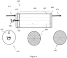
- Sequestration Material 1 is configured such that each of the at least two materials are included together in a filter element.
- filter element refers to any device, system, article or container in which each of the sequestration materials are located in close physical proximity, and preferably at essentially the same location within the system.
- Sequestration Material 1 is configured such that each of the at least two materials are included together in a solid core.
- solid core refers to relatively porous solid which contains and/or has embedded therein two or more of sequestration materials such that such materials are accessible to fluids passing through said any solid core.
- the one or more sequestration materials are substantially homogeneously distributed throughout the solid core.
- the solid core of the present invention is included in or comprises a filter element.
- Sequestration Material 1 is configured such that each of the at least two materials are included in a solid core.
- Sequestration Material 2 is configured such that each of the at least two materials are included together in a filter element.
- Sequestration Material 2 is configured such that all of materials are included in a solid core.
- Sequestration Material 3 is configured such that each of the at least two materials are included together in a filter element.
- Sequestration Material 3 is configured such that all of materials are included in a solid core.
- Sequestration Material 4 is configured such that each of the at least two materials are included together in a filter element.
- Sequestration Material 4 is configured such that all of materials are included in a solid core.
- the present invention includes heat transfer methods according to Heat Transfer Method 1 in which the refrigerant is Refrigerant 1 and in which the sequestration material is Sequestration Material 1 located in a filter element and/or in a solid core.
- the present invention includes heat transfer methods according to Heat Transfer Method 1 in which the refrigerant is Refrigerant 1 and in which the sequestration material is Sequestration Material 2 located in a filter element and/or in a solid core.
- the present invention includes heat transfer methods according to Heat Transfer Method 1 in which the refrigerant is Refrigerant 1 and in which the sequestration material is Sequestration Material 3 located in a filter element and/or in a solid core.
- the present invention includes heat transfer methods according to Heat Transfer Method 1 in which the refrigerant is Refrigerant 1 and in which the sequestration material is Sequestration Material 4 located in a filter element and/or in a solid core.
- the present invention includes heat transfer methods according to Heat Transfer Method 1 in which the refrigerant is Refrigerant 2 and in which the sequestration material is Sequestration Material 1 located in a filter element and/or in a solid core.
- the present invention includes heat transfer methods according to Heat Transfer Method 1 in which the refrigerant is Refrigerant 2 and in which the sequestration material is Sequestration Material 2 located in a filter element and/or in a solid core.
- the present invention includes heat transfer methods according to Heat Transfer Method 1 in which the refrigerant is Refrigerant 2 and in which the sequestration material is Sequestration Material 3 located in a filter element and/or in a solid core.
- the present invention includes heat transfer methods according to Heat Transfer Method 1 in which the refrigerant is Refrigerant 2 and in which the sequestration material is Sequestration Material 4 located in a filter element and/or in a solid core.
- the present invention includes heat transfer methods according to Heat Transfer Method 1 in which the refrigerant is Refrigerant 3 and in which the sequestration material is Sequestration Material 1 located in a filter element and/or in a solid core.
- the present invention includes heat transfer methods according to Heat Transfer Method 1 in which the refrigerant is Refrigerant 3 and in which the sequestration material is Sequestration Material 2 located in a filter element and/or in a solid core.
- the present invention includes heat transfer methods according to Heat Transfer Method 1 in which the refrigerant is Refrigerant 3 and in which the sequestration material is Sequestration Material 3 located in a filter element and/or in a solid core.
- the present invention includes heat transfer methods according to Heat Transfer Method 1 in which the refrigerant is Refrigerant 3 and in which the sequestration material is Sequestration Material 4 located in a filter element and/or in a solid core.
- the present invention includes heat transfer methods according to Heat Transfer Method 1 in which the refrigerant is Refrigerant 4 and in which the sequestration material is Sequestration Material 1 located in a filter element and/or in a solid core.
- the present invention includes heat transfer methods according to Heat Transfer Method 1 in which the refrigerant is Refrigerant 4 and in which the sequestration material is Sequestration Material 2 located in a filter element and/or in a solid core.
- the present invention includes heat transfer methods according to Heat Transfer Method 1 in which the refrigerant is Refrigerant 4 and in which the sequestration material is Sequestration Material 3 located in a filter element and/or in a solid core.
- the present invention includes heat transfer methods according to Heat Transfer Method 1 in which the refrigerant is Refrigerant 4 and in which the sequestration material is Sequestration Material 4 located in a filter element and/or in a solid core.
- the present invention includes heat transfer methods according to Heat Transfer Method 1 in which the refrigerant is Refrigerant 5 and in which the sequestration material is Sequestration Material 1 located in a filter element and/or in a solid core.
- the present invention includes heat transfer methods according to Heat Transfer Method 1 in which the refrigerant is Refrigerant 5 and in which the sequestration material is Sequestration Material 2 located in a filter element and/or in a solid core.
- the present invention includes heat transfer methods according to Heat Transfer Method 1 in which the refrigerant is Refrigerant 5 and in which the sequestration material is Sequestration Material 3 located in a filter element and/or in a solid core.
- the present invention includes heat transfer methods according to Heat Transfer Method 1 in which the refrigerant is Refrigerant 5 and in which the sequestration material is Sequestration Material 4 located in a filter element and/or in a solid core.
- the present invention includes heat transfer methods according to Heat Transfer Method 1 in which the refrigerant is Refrigerant 6 and in which the sequestration material is Sequestration Material 1 located in a filter element and/or in a solid core.
- the present invention includes heat transfer methods according to Heat Transfer Method 1 in which the refrigerant is Refrigerant 6 and in which the sequestration material is Sequestration Material 2 located in a filter element and/or in a solid core.
- the present invention includes heat transfer methods according to Heat Transfer Method 1 in which the refrigerant is Refrigerant 6 and in which the sequestration material is Sequestration Material 3 located in a filter element and/or in a solid core.
- the present invention includes heat transfer methods according to Heat Transfer Method 1 in which the refrigerant is Refrigerant 6 and in which the sequestration material is Sequestration Material 4 located in a filter element and/or in a solid core.
- the present invention includes heat transfer methods according to Heat Transfer Method 1 in which the refrigerant is Refrigerant 7 and in which the sequestration material is Sequestration Material 1 located in a filter element and/or in a solid core.
- the present invention includes heat transfer methods according to Heat Transfer Method 1 in which the refrigerant is Refrigerant 7 and in which the sequestration material is Sequestration Material 2 located in a filter element and/or in a solid core.
- the present invention includes heat transfer methods according to Heat Transfer Method 1 in which the refrigerant is Refrigerant 7 and in which the sequestration material is Sequestration Material 3 located in a filter element and/or in a solid core.
- the present invention includes heat transfer methods according to Heat Transfer Method 1 in which the refrigerant is Refrigerant 7 and in which the sequestration material is Sequestration Material 4 located in a filter element and/or in a solid core.
- the present invention includes heat transfer methods according to Heat Transfer Method 1 in which the refrigerant is Refrigerant 8 and in which the sequestration material is Sequestration Material 1 located in a filter element and/or in a solid core.
- the present invention includes heat transfer methods according to Heat Transfer Method 1 in which the refrigerant is Refrigerant 8 and in which the sequestration material is Sequestration Material 2 located in a filter element and/or in a solid core.
- the present invention includes heat transfer methods according to Heat Transfer Method 1 in which the refrigerant is Refrigerant 8 and in which the sequestration material is Sequestration Material 3 located in a filter element and/or in a solid core.
- the present invention includes heat transfer methods according to Heat Transfer Method 1 in which the refrigerant is Refrigerant 8 and in which the sequestration material is Sequestration Material 4 located in a filter element and/or in a solid core.
- he present invention also includes methods for transferring heat of the type comprising evaporating refrigerant liquid and condensing refrigerant vapor in a plurality of repeating cycles, said method comprising:
- the present invention also includes methods for transferring heat of the type comprising evaporating refrigerant liquid and condensing refrigerant vapor in a plurality of repeating cycles, said method comprising:
- the present invention includes heat transfer methods according to Heat Transfer Method 2 in which the refrigerant is Refrigerant 1 and in which the sequestration material is Sequestration Material 1 located in a filter element and/or in a solid core.
- the present invention includes heat transfer methods according to Heat Transfer Method 2 in which the refrigerant is Refrigerant 1 and in which the sequestration material is Sequestration Material 2 located in a filter element and/or in a solid core.
- the present invention includes heat transfer methods according to Heat Transfer Method 2 in which the refrigerant is Refrigerant 1 and in which the sequestration material is Sequestration Material 3 located in a filter element and/or in a solid core.
- the present invention includes heat transfer methods according to Heat Transfer Method 2 in which the refrigerant is Refrigerant 1 and in which the sequestration material is Sequestration Material 4 located in a filter element and/or in a solid core.
- the present invention includes heat transfer methods according to Heat Transfer Method 2 in which the refrigerant is Refrigerant 2 and in which the sequestration material is Sequestration Material 1 located in a filter element and/or in a solid core.
- the present invention includes heat transfer methods according to Heat Transfer Method 2 in which the refrigerant is Refrigerant 2 and in which the sequestration material is Sequestration Material 2 located in a filter element and/or in a solid core.
- the present invention includes heat transfer methods according to Heat Transfer Method 2 in which the refrigerant is Refrigerant 2 and in which the sequestration material is Sequestration Material 3 located in a filter element and/or in a solid core.
- the present invention includes heat transfer methods according to Heat Transfer Method 2 in which the refrigerant is Refrigerant 2 and in which the sequestration material is Sequestration Material 4 located in a filter element and/or in a solid core.
- the present invention includes heat transfer methods according to Heat Transfer Method 2 in which the refrigerant is Refrigerant 3 and in which the sequestration material is Sequestration Material 1 located in a filter element and/or in a solid core.
- the present invention includes heat transfer methods according to Heat Transfer Method 2 in which the refrigerant is Refrigerant 3 and in which the sequestration material is Sequestration Material 2 located in a filter element and/or in a solid core.
- the present invention includes heat transfer methods according to Heat Transfer Method 2 in which the refrigerant is Refrigerant 3 and in which the sequestration material is Sequestration Material 3 located in a filter element and/or in a solid core.
- the present invention includes heat transfer methods according to Heat Transfer Method 2 in which the refrigerant is Refrigerant 3 and in which the sequestration material is Sequestration Material 4 located in a filter element and/or in a solid core.
- the present invention includes heat transfer methods according to Heat Transfer Method 2 in which the refrigerant is Refrigerant 4 and in which the sequestration material is Sequestration Material 1 located in a filter element and/or in a solid core.
- the present invention includes heat transfer methods according to Heat Transfer Method 2 in which the refrigerant is Refrigerant 4 and in which the sequestration material is Sequestration Material 2 located in a filter element and/or in a solid core.
- the present invention includes heat transfer methods according to Heat Transfer Method 2 in which the refrigerant is Refrigerant 4 and in which the sequestration material is Sequestration Material 3 located in a filter element and/or in a solid core.
- the present invention includes heat transfer methods according to Heat Transfer Method 2 in which the refrigerant is Refrigerant 4 and in which the sequestration material is Sequestration Material 4 located in a filter element and/or in a solid core.
- the present invention includes heat transfer methods according to Heat Transfer Method 2 in which the refrigerant is Refrigerant 5 and in which the sequestration material is Sequestration Material 1 located in a filter element and/or in a solid core.
- the present invention includes heat transfer methods according to Heat Transfer Method 2 in which the refrigerant is Refrigerant 5 and in which the sequestration material is Sequestration Material 2 located in a filter element and/or in a solid core.
- the present invention includes heat transfer methods according to Heat Transfer Method 2 in which the refrigerant is Refrigerant 5 and in which the sequestration material is Sequestration Material 3 located in a filter element and/or in a solid core.
- the present invention includes heat transfer methods according to Heat Transfer Method 2 in which the refrigerant is Refrigerant 5 and in which the sequestration material is Sequestration Material 4 located in a filter element and/or in a solid core.
- the present invention includes heat transfer methods according to Heat Transfer Method 2 in which the refrigerant is Refrigerant 6 and in which the sequestration material is Sequestration Material 1 located in a filter element and/or in a solid core.
- the present invention includes heat transfer methods according to Heat Transfer Method 2 in which the refrigerant is Refrigerant 6 and in which the sequestration material is Sequestration Material 2 located in a filter element and/or in a solid core.
- the present invention includes heat transfer methods according to Heat Transfer Method 2 in which the refrigerant is Refrigerant 6 and in which the sequestration material is Sequestration Material 3 located in a filter element and/or in a solid core.
- the present invention includes heat transfer methods according to Heat Transfer Method 2 in which the refrigerant is Refrigerant 6 and in which the sequestration material is Sequestration Material 4 located in a filter element and/or in a solid core.
- the present invention includes heat transfer methods according to Heat Transfer Method 2 in which the refrigerant is Refrigerant 7 and in which the sequestration material is Sequestration Material 1 located in a filter element and/or in a solid core.
- the present invention includes heat transfer methods according to Heat Transfer Method 2 in which the refrigerant is Refrigerant 7 and in which the sequestration material is Sequestration Material 2 located in a filter element and/or in a solid core.
- the present invention includes heat transfer methods according to Heat Transfer Method 2 in which the refrigerant is Refrigerant 7 and in which the sequestration material is Sequestration Material 3 located in a filter element and/or in a solid core.
- the present invention includes heat transfer methods according to Heat Transfer Method 2 in which the refrigerant is Refrigerant 7 and in which the sequestration material is Sequestration Material 4 located in a filter element and/or in a solid core.
- the present invention includes heat transfer methods according to Heat Transfer Method 2 in which the refrigerant is Refrigerant 8 and in which the sequestration material is Sequestration Material 1 located in a filter element and/or in a solid core.
- the present invention includes heat transfer methods according to Heat Transfer Method 2 in which the refrigerant is Refrigerant 8 and in which the sequestration material is Sequestration Material 2 located in a filter element and/or in a solid core.
- the present invention includes heat transfer methods according to Heat Transfer Method 2 in which the refrigerant is Refrigerant 8 and in which the sequestration material is Sequestration Material 3 located in a filter element and/or in a solid core.
- the present invention includes heat transfer methods according to Heat Transfer Method 2 in which the refrigerant is Refrigerant 8 and in which the sequestration material is Sequestration Material 4 located in a filter element and/or in a solid core.
- the present invention includes a refrigeration system comprising:
- the present invention includes Refrigerant System 1 in which the refrigerant is Refrigerant 1 and the sequestration material is Sequestration Material 1.
- the present invention includes Refrigerant System 1 in which the refrigerant is Refrigerant 1 and the sequestration material is Sequestration Material 2.
- the present invention includes Refrigerant System 1 in which the refrigerant is Refrigerant 1 and the sequestration material is Sequestration Material 3.
- the present invention includes Refrigerant System 1 in which the refrigerant is Refrigerant 1 and the sequestration material is Sequestration Material 4.
- the present invention includes Refrigerant System 1 in which the refrigerant is Refrigerant 2 and the sequestration material is Sequestration Material 1.
- the present invention includes Refrigerant System 1 in which the refrigerant is Refrigerant 2 and the sequestration material is Sequestration Material 2.
- the present invention includes Refrigerant System 1 in which the refrigerant is Refrigerant 2 and the sequestration material is Sequestration Material 3.
- the present invention includes Refrigerant System 1 in which the refrigerant is Refrigerant 2 and the sequestration material is Sequestration Material 4.
- the present invention includes Refrigerant System 1 in which the refrigerant is Refrigerant 3 and the sequestration material is Sequestration Material 1.
- the present invention includes Refrigerant System 1 in which the refrigerant is Refrigerant 3 and the sequestration material is Sequestration Material 2.
- the present invention includes Refrigerant System 1 in which the refrigerant is Refrigerant 3 and the sequestration material is Sequestration Material 3.
- the present invention includes Refrigerant System 1 in which the refrigerant is Refrigerant 3 and the sequestration material is Sequestration Material 4.
- the present invention includes Refrigerant System 1 in which the refrigerant is Refrigerant 4 and the sequestration material is Sequestration Material 1.
- the present invention includes Refrigerant System 1 in which the refrigerant is Refrigerant 4 and the sequestration material is Sequestration Material 2.
- the present invention includes Refrigerant System 1 in which the refrigerant is Refrigerant 4 and the sequestration material is Sequestration Material 3.
- the present invention includes Refrigerant System 1 in which the refrigerant is Refrigerant 4 and the sequestration material is Sequestration Material 4.
- the present invention includes Refrigerant System 1 in which the refrigerant is Refrigerant 5 and the sequestration material is Sequestration Material 1.
- the present invention includes Refrigerant System 1 in which the refrigerant is Refrigerant 5 and the sequestration material is Sequestration Material 2.
- the present invention includes Refrigerant System 1 in which the refrigerant is Refrigerant 5 and the sequestration material is Sequestration Material 3.
- the present invention includes Refrigerant System 1 in which the refrigerant is Refrigerant 5 and the sequestration material is Sequestration Material 4.
- the present invention includes Refrigerant System 1 in which the refrigerant is Refrigerant 6 and the sequestration material is Sequestration Material 1.
- the present invention includes Refrigerant System 1 in which the refrigerant is Refrigerant 6 and the sequestration material is Sequestration Material 2.
- the present invention includes Refrigerant System 1 in which the refrigerant is Refrigerant 6 and the sequestration material is Sequestration Material 3.
- the present invention includes Refrigerant System 1 in which the refrigerant is Refrigerant 6 and the sequestration material is Sequestration Material 4.
- the present invention includes Refrigerant System 1 in which the refrigerant is Refrigerant 7 and the sequestration material is Sequestration Material 1.
- the present invention includes Refrigerant System 1 in which the refrigerant is Refrigerant 7 and the sequestration material is Sequestration Material 2.
- the present invention includes Refrigerant System 1 in which the refrigerant is Refrigerant 7 and the sequestration material is Sequestration Material 3.
- the present invention includes Refrigerant System 1 in which the refrigerant is Refrigerant 7 and the sequestration material is Sequestration Material 4.
- the present invention includes Refrigerant System 1 in which the refrigerant is Refrigerant 8 and the sequestration material is Sequestration Material 1.
- the present invention includes Refrigerant System 1 in which the refrigerant is Refrigerant 8 and the sequestration material is Sequestration Material 2.
- the present invention includes Refrigerant System 1 in which the refrigerant is Refrigerant 8 and the sequestration material is Sequestration Material 3.
- the present invention includes Refrigerant System 1 in which the refrigerant is Refrigerant 8 and the sequestration material is Sequestration Material 4.
- the present invention also includes a heat transfer refrigeration system comprising a heat transfer composition circulating in the heat transfer system that has been installed and in operation for a period of at least about 1 year, said heat transfer composition comprising a lubricant and a refrigerant according to the present invention and said system comprising a sequestration material of the present invention and in which the refrigerant and/or the lubricant has an iodide content of not greater than about 1100 ppm based on the weight of refrigerant and/or about 1100 ppm based on the weight of the lubricant.
- Heat transfer compositions according to this paragraph are referred to herein as Heat Transfer System 1.
- the term "installed and in operation” refers to new installations and refurbished installations which have been installed or modified according to the present invention, which have been in regular operation.
- regular operation includes time periods in which the system would normally be shut down for maintenance and/or repairs and during other periods during which the system would normally not be operating but would be considered in service.
- the present invention includes Heat Transfer System 1 in which the refrigerant is Refrigerant 1, the lubricant comprises POE, and the sequestration material is Sequestration Material 1.
- the present invention includes Heat Transfer System 1 in which the refrigerant is Refrigerant 1, the lubricant comprises POE, and the sequestration material is Sequestration Material 2.
- the present invention includes Heat Transfer System 1 in which the refrigerant is Refrigerant 1, the lubricant comprises POE, and the sequestration material is Sequestration Material 3.
- the present invention includes Heat Transfer System 1 in which the refrigerant is Refrigerant 1, the lubricant comprises POE, and the sequestration material is Sequestration Material 4.
- the present invention includes Heat Transfer System 1 in which the refrigerant is Refrigerant 2, the lubricant comprises POE, and the sequestration material is Sequestration Material 1.
- the present invention includes Heat Transfer System 1 in which the refrigerant is Refrigerant 2, the lubricant comprises POE, and the sequestration material is Sequestration Material 2.
- the present invention includes Heat Transfer System 1 in which the refrigerant is Refrigerant 2, the lubricant comprises POE, and the sequestration material is Sequestration Material 3.
- the present invention includes Heat Transfer System 1 in which the refrigerant is Refrigerant 2, the lubricant comprises POE, and the sequestration material is Sequestration Material 4.
- the present invention includes Heat Transfer System 1 in which the refrigerant is Refrigerant 3, the lubricant comprises POE, and the sequestration material is Sequestration Material 1.
- the present invention includes Heat Transfer System 1 in which the refrigerant is Refrigerant 3, the lubricant comprises POE, and the sequestration material is Sequestration Material 2.
- the present invention includes Heat Transfer System 1 in which the refrigerant is Refrigerant 3, the lubricant comprises POE, and the sequestration material is Sequestration Material 3.
- the present invention includes Heat Transfer System 1 in which the refrigerant is Refrigerant 3, the lubricant comprises POE, and the sequestration material is Sequestration Material 4.
- the present invention includes Heat Transfer System 1 in which the refrigerant is Refrigerant 4, the lubricant comprises POE, and the sequestration material is Sequestration Material 1.
- the present invention includes Heat Transfer System 1 in which the refrigerant is Refrigerant 4, the lubricant comprises POE, and the sequestration material is Sequestration Material 2.
- the present invention includes Heat Transfer System 1 in which the refrigerant is Refrigerant 4, the lubricant comprises POE, and the sequestration material is Sequestration Material 3.
- the present invention includes Heat Transfer System 1 in which the refrigerant is Refrigerant 4, the lubricant comprises POE, and the sequestration material is Sequestration Material 4.
- the present invention includes Heat Transfer System 1 in which the refrigerant is Refrigerant 5, the lubricant comprises POE, and the sequestration material is Sequestration Material 1.
- the present invention includes Heat Transfer System 1 in which the refrigerant is Refrigerant 5, the lubricant comprises POE, and the sequestration material is Sequestration Material 2.
- the present invention includes Heat Transfer System 1 in which the refrigerant is Refrigerant 5, the lubricant comprises POE, and the sequestration material is Sequestration Material 3.
- the present invention includes Heat Transfer System 1 in which the refrigerant is Refrigerant 5, the lubricant comprises POE, and the sequestration material is Sequestration Material 4.
- the present invention includes Heat Transfer System 1 in which the refrigerant is Refrigerant 6, the lubricant comprises POE, and the sequestration material is Sequestration Material 1.
- the present invention includes Heat Transfer System 1 in which the refrigerant is Refrigerant 6, the lubricant comprises POE, and the sequestration material is Sequestration Material 2.
- the present invention includes Heat Transfer System 1 in which the refrigerant is Refrigerant 6, the lubricant comprises POE, and the sequestration material is Sequestration Material 3.
- the present invention includes Heat Transfer System 1 in which the refrigerant is Refrigerant 6, the lubricant comprises POE, and the sequestration material is Sequestration Material 4.
- the present invention includes Heat Transfer System 1 in which the refrigerant is Refrigerant 7, the lubricant comprises POE, and the sequestration material is Sequestration Material 1.
- the present invention includes Heat Transfer System 1 in which the refrigerant is Refrigerant 7, the lubricant comprises POE, and the sequestration material is Sequestration Material 2.
- the present invention includes Heat Transfer System 1 in which the refrigerant is Refrigerant 7, the lubricant comprises POE, and the sequestration material is Sequestration Material 3.
- the present invention includes Heat Transfer System 1 in which the refrigerant is Refrigerant 7, the lubricant comprises POE, and the sequestration material is Sequestration Material 4.
- the present invention includes Heat Transfer System 1 in which the refrigerant is Refrigerant 8, the lubricant comprises POE, and the sequestration material is Sequestration Material 1.
- the present invention includes Heat Transfer System 1 in which the refrigerant is Refrigerant 8, the lubricant comprises POE, and the sequestration material is Sequestration Material 2.
- the present invention includes Heat Transfer System 1 in which the refrigerant is Refrigerant 8, the lubricant comprises POE, and the sequestration material is Sequestration Material 3.
- the present invention includes Heat Transfer System 1 in which the refrigerant is Refrigerant 8, the lubricant comprises POE, and the sequestration material is Sequestration Material 4.
- a Heat Transfer System 1 according to each of the preceding paragraphs which have been installed and in operation for a period of at least about 2 years.
- a Heat Transfer System 1 according to each of the preceding paragraphs which have been installed and in operation for a period of at least about 5 years.
- a Heat Transfer System 1 according to each of the preceding paragraphs in which the refrigerant and/or the lubricant has an fluoride content of not greater than about 500 ppm based on the weight of refrigerant and/or 500 ppm based on the weight of the lubricant) .
- non-flammable refers to compounds or compositions which are determined to be non-flammable in accordance with ASTM standard E-681-2001 at conditions described in ASHRAE Standard 34-2013 and described in Appendix B1 to ASHRAE Standard 34-2013.
- the present invention includes methods for transferring heat comprising evaporating refrigerant liquid and condensing refrigerant vapor in a plurality of repeating cycles.
- the methods aspects of the present invention thus encompass broadly any and all such methods, including vapor compression refrigeration, absorption refrigeration, Rankine Cycles and heat pipes.
- the refrigerant travels or is transported through a cycle that involves the refrigerant being exposed to a variety of temperatures, pressures, materials of construction and other components of the heat transfer composition, such as for example lubricants in the case of compression refrigeration systems which include lubricated compressors.
- the refrigerant of the present invention which includes at least 5% by weight of lower alkyl iodoflurocarbon, and preferably CF3I, tends to produce degradation products, such as iodide (I - ), iodine (I 2 ) and fluoride (F - ), which can negatively impact the reliability of the heat transfer system, and/or the stability of any lubricant present in the system.
- preferred embodiments of the present methods include the step of exposing at least a portion of the refrigerant, and preferably substantially all of the refrigerant, and even more preferably all of refrigerant circulating in the system, and even more preferably substantially all of the heat transfer composition circulating in the system, to a sequestration material of the present invention.
- Applicants have found that unexpected advantages can be achieved in such methods by conducting said exposing step so as to a have an exposing temperature of at least about 10C, more preferably at least about 20C, or preferably at least about 30°C.
- the exposing step can involve the temperature of the refrigerant being at least about 10C, 20C or 30C, or the temperature of the sequestration material being at least about 10C, 20C or 30C, it is generally preferred that both the refrigerant and the sequestration material are at a temperature of at least about 10c, 20C or 30C, during at least a substantial portion, and preferably during substantially all of, the time that the refrigerant is in contact with the sequestration material for a given exposing step.
- Preferred embodiments of the present methods also include the sequestration material comprising a combination of at least: i. activated alumina; ii. a zeolite molecular sieve comprising copper, silver, lead or a combination thereof; iii. an anion exchange resin, and iv. a moisture-removing material, preferably a moisture-removing molecular sieve.
- the sequestration material comprising a combination of at least: i. activated alumina; ii. a zeolite molecular sieve comprising copper, silver, lead or a combination thereof; iii. an anion exchange resin, and iv. a moisture-removing material, preferably a moisture-removing molecular sieve.
- the heat transfer methods comprise creating a stream or flow or body of refrigerant fluid and/or creating a stream or flow or body of refrigerant fluid
- the exposing step of the present invention comprises in such preferred embodiments locating in one or more of said streams or flows or bodies an amount or volume, and preferably a fixed volume, of a sequestration material of the present invention such that the refrigerant and/or the lubricant flows over, flows over, through or otherwise is in intimate contact with the sequestration material.
- the stream or flow in which the sequestration material is located comprises a stream or flow that is part of the refrigeration cycle.
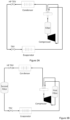
- the exposing step may comprising placing a fixed volume of sequestration material in the compressor discharge stream of a vapor compression system, preferably wherein said compressor discharge temperature is at least about 10C, more preferably at least about 20C, or preferably at least about 30C.
- the exposing step comprises taking a slip or side stream of the refrigerant circulating in the heat transfer cycle and exposing that slip or side stream to the sequestration material, preferably where the slip or side stream is at a temperature of at least about 10C, more preferably 20C and even more preferably at least about 30C, and then returning the slip or side stream to the circulating refrigerant, either downstream from where it was drawn, upstream from where it was drawn, or returning a portion downstream and a portion upstream.
- the slip or side stream may be taken from a refrigerant stream that is less than about 10C, or about 20C, or less than 30C, and the slip or side stream is heated to above about 10C, or about 20C, or above about 30C, and then exposed to the sequestration material and/or the sequestration material is maintained at a temperature above about 10C, or 20C or above about 30C.
- the exposing step may comprises dissolving or suspending the sequestration material, or locating the sequestration material, in at least a part of the stream or flow of refrigerant and/or lubricant that is circulating in the refrigeration cycle or a subportion of the refrigeration cycle.
- the sequestration material can be a separate, fixed volume or it can not be a separate fixed volume but instead travels with the refrigerant and/or during at least a portion of the refrigerant cycle and/or lubricant cycle, and prefearably during a portion of the cycle in which the refrigerant temperature or the lubricant temperature is at least about 10C, or about 20C, more preferably at least about 30C.
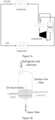
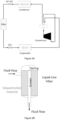
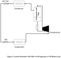
- one or more of the sequestration materials comprises; i. activated alumina; ii. a zeolite molecular sieve comprising copper, silver, lead or a combination thereof; iii. an anion exchange resin, and iv. a moisture-removing material, preferably a moisture-removing molecular sieve, and in preferred embodiments all of these materials together, can be located inside the oil separator, or in some cases outside but downstream of the oil separator, such that the liquid lubricant contacts the sequestration material(s), as shown in Figure 5 hereof.
- the present invention also includes one or more of the materials being located in the refrigerant liquid which exits the condenser.
- At least a portion of, and in preferred embodiments substantially all of the sequestration material is present in the compressor discharge refrigerant stream, that is, in the discharge line, and preferably the exposing temperature in such location is from about 70°C to about 140°C.
- the exposing temperature in such location is from about 70°C to about 140°C.
- at least a portion of, and in preferred embodiments substantially all of, the sequestration material is present in the liquid refrigerant leaving the condenser, and the temperatures to which the sequestration material is exposed may be from about 10°C to about 80°C.
- the sequestration material is present in the suction line of the compressor, and the temperatures in such a case to which the sequestration material is exposed may be from about - 30°C to about 30°C.
- the exposing step is carried by out at a temperature of from about 50°C to about 140°C, more preferably from about 70°C to about 140°C.
- the exposing step is carried by out at a temperature of from about 20°C to about 80°C or from about -30°C to about 20°C, and in such embodiments the sequestration material preferably comprises a combination of:
- the sequestration material may comprise one or more of:a) copper or a copper alloy; b) a molecular sieve (preferably a zeolite) comprising copper, silver, lead or a combination thereof, c) an anion exchange resin, d) moisture removal materials, e) and activated alumina, or a combination of any two or more of these materials
- the sequestration material may be copper, or a copper alloy, preferably copper.
- the copper alloy may comprise, in addition to copper, one or more further metals, such as tin, aluminium, silicon, nickel or a combination thereof.
- the copper alloy may comprise one or more non-metal elements, e.g. carbon, nitrogen, silicon, oxygen or a combination thereof.
- the copper alloy may comprise varying amounts of copper.
- the copper alloy may comprise at least about 5 wt%, at least about 15 wt%, at least about 30 wt%, at least about 50 wt%, at least about 70 wt% or at least about 90 wt% of copper, based on the total weight of the copper alloy.
- the copper alloy may comprise from about 5 wt% to about 95 wt%, from about 10 wt% to about 90 wt%, from about 15 wt% to about 85 wt%, from about 20 wt% to about 80 wt%, form about 30 wt% to about 70 wt%, or from about 40 wt% to about 60 wt% of copper, based on the total weight of the copper alloy.
- copper may be used as a sequestration material.
- the copper metal may contain impurity levels of other elements or compounds.
- the copper metal may contain at least about 99 wt%, more preferably at least about 99.5 wt%, more preferably at least about 99.9 wt% of elemental copper.
- the copper or copper alloy may be in any form which allows the refrigerant to contact the surface of the copper or copper alloy.
- the form of the copper or copper alloy is selected to maximize the surface area of the copper or copper alloy (i.e. to maximize the area which is in contact with the refrigerant).
- the metal may be in the form of a mesh, wool, spheres, cones, cylinders etc.
- sphere refers to a three dimensional shape where the difference between the largest diameter and the smallest diameter is about 10% or less of the largest diameter.
- the copper or copper alloy may have a BET surface area of at least about 10m 2 /g, at least about 20m 2 /g, at least about 30m 2 /g, at least about 40m 2 /g or at least about 50m 2 /g.
- the BET-surface area may be measured in accordance with ASTM D6556-10.
- the BET surface area of the copper or copper alloy may be from about 0.01 to about 1.5m 2 per kg of refrigerant, preferably from about 0.02 to about 0.5m 2 per kg of refrigerant.
- the copper or copper alloy may have a surface area of about 0.08m 2 per kg of refrigerant.
- the sequestration material may comprise a zeolite molecular sieve (.
- the zeolite molecular sieve comprises copper, silver, lead or a combination thereof, preferably at least silver.
- the zeolite molecular sieve contains an amount of metal, and preferably in certain embodiments silver, of from about 1% to about 30% by weight, or preferably from about 5% to about 20% by weight, based on the total weight of the zeolite.
- the metal i.e. copper, silver and/or lead
- the metal may be present in a single oxidation state, or in a variety of oxidation states (e.g. a copper zeolite may comprise both Cu(I) and Cu(II)).
- the zeolite molecular sieve may comprise metals other than silver, lead, and/or copper.
- the zeolite may have openings which have a size across their largest dimension of from about 5 to 40 ⁇ .
- the zeolite may have openings which have a size across their largest dimension of about 35 ⁇ or less.
- the zeolite has openings which have a size across their largest dimension of from about 15 to about 35 ⁇ .
- Zeolite such as IONSIV D7310-C has activated sites that applicants have found to ef-fectively remove specific decomposition products in accordance with the present in-vention.
- the sequestration material comprises a zeolite molecular sieve comprising copper, silver, lead or a combination thereof
- the molecular sieve e.g. zeolite
- the molecular sieve may be present in an amount of from about 1wt% to about 30wt%, such as from about 2wt% to about 25wt% relative to the total amount of molecular sieve (e.g.
- the sequestration material comprises a zeolite molecular sieve comprising silver, and in such embodiments the molecular sieve may be present in an amount of at least 5% parts by weight (pbw), preferably from about 5pbw to about 30 pbw, or from about 5 pbw to about 20pbw, per 100 parts by weight of lubricant (pphl) based on the total amount of molecular sieve (e.g. zeolite) and lubricant in the heat transfer system being treated.
- pphl lubricant
- the preferred embodiments as described in this paragraph have been found to have exceptional ability to remove fluoride from heat transfer compositions as described herein.
- the amount of the silver present in the molecular sieve is from about 1% to about 30% by weight, or preferably from about 5% to about 20% by weight, based on the total weight of the zeolite.
- the sequestration material comprises a zeolite molecular sieve comprising silver
- the molecular sieve e.g. zeolite
- the molecular sieve may be present in an amount of at least 10 pphl, preferably from about 10 pphlto about 30 pphl, or from about 10 pphl to about 20 pphl by weight relative to the total amount of molecular sieve (e.g. zeolite), and lubricant in the heat transfer system being treated.
- the preferred embodiments as described in this paragraph have been found to have exceptional ability to remove iodide from heat transfer compositions as described herein.
- the amount of the silver present in the molecular sieve is from about 1% to about 30% by weight, or preferably from about 5% to about 20% by weight, based on the total weight of the zeolite.
- the sequestration material comprises a zeolite molecular sieve comprises silver, and in such embodiments the molecular sieve may be present in an amount of at least pphl, preferably from about 15 pphlto about 30 pphl, or from about 15 pphl to about 20 pphl by weightrelative to the total amount of molecular sieve , and lubricant in the heat transfer system being treated.
- the preferred embodiments as described in this paragraph have been found to have exceptional ability to reduce TAN levels in the heat transfer compositions as described herein.
- the amount of the silver present in the molecular sieve is from about 1% to about 30% by weight, or preferably from about 5% to about 20% by weight, based on the total weight of the zeolite.
- the zeolite molecular sieve is present in an amount of at least about 15 pphl, or at least about 18 pphl relative to the total amount of molecular sieve and lubricant in the system. Therefore, the molecular sieve may be present in an amount of from about 15 pphl to about 30 pphl, or from about 18 pphl to about 25 pphl relative to the total amount of molecular sieve and lubricant present in the system.
- the zeolite may be present in an amount of about 5 pphl or about 21 pphl relative to the total amount of molecular sieve, and lubricant in the system.
- the amount of zeolite molecular sieve described herein refers to the dry weight of the molecular sieve .
- dry weight of the sequestration materials means that the material has 50 ppm or less of moisture.
- the sequestration material may comprise an anion exchange resin.
- the anion exchange resin is a strongly basic anion exchange resin.
- the strongly basic anion exchange resin may be a type 1 resin or a type 2 resin.
- the anion exchange resin is a type 1 strongly basic anion exchange resin.
- the anion exchange resin generally comprises a positively charged matrix and exchangeable anions.
- the exchangeable anions may be chloride anions (Cl - ) and/or hydroxide anions (OH).
- the anion exchange resin may be provided in any form.
- the anion exchange resin may be provided as beads.
- the beads may have a size across their largest dimension of from about 0.3mm to about 1.2mm, when dry.
- the anion exchange resin may be present in an amount of from about 1 pphl to about 60 pphl, or from about 5 pphl to about 60 pphl, or from about 20 pphl to about 50 pphl, or from about 20 pphl to about 30 pphl, or from about 1 pphl to about 25 pphl, such as from about 2 pphl to about 20 pphl based on the total amount of anion exchange resin and lubricant in the system.
- the anionic exchange resin is present in an amount of at least about 10 pphl, or at least about 15 pphl relative to the total amount of anionic exchange resin and lubricant in the system. Therefore, the anion exchange resin may be present in an amount of from about 10 pphl to about 25 pphl, or from about 15 pphl to about 20 pphl relative to the total amount of anion exchange resin and lubricant in the system.
- anion exchange resin may be present in an amount of about 4 pphl or about 16 pphl based on the total amount of anion exchange resin and lubricant present in the system.
- weak base anion resin refers to resins in the free base form, which are preferably e functionalized with a tertiary amine (uncharged). Tertiary amine contains a free lone pair of electrons on the nitrogen, which results in it being readily protonated in presence of an acid.
- the ion exchange resin as used according to the present invention is protonated by the acid, then attracts and binds the anionic counter ion for full acid removal, without contributing any additional species back into solution.
- Amberlyst A21 is a preferred material in that applicants have found it to be advantageous because it provides a macroporous structure makes it physically very stable and resistant to breakage, and applicants have found that it can withstand high flow rates of the refrigeration system over relatibely long periods of time, including preferably over the lifetime of the system.
- the amount of anion exchange resin described herein refers to the dry weight of the anion exchange resin.
- dry weight of the sequestration materials means that the material has 50 ppm or less of moisture.
- pphl of a particular sequestration material means the parts per hundred of the particular sequestration material by weight based on the total weight of that particular sequestration material and lubricant in the system.
- a preferred sequestration material is a moisture removing material.
- the moisture removing material comprises, consists essentially of or consists of a moisture-removing molecular sieve.
- Preferred moisture-removing molecular sieves include those commonly known as sodium aluminosilicate molecular sieves, and such materials are preferably crystalline metal aluminosilicates having a three dimensional interconnecting network of silica and alumina tetrahedra. Applicants have found that such materials are effective in the systems of the present invention to remove moisture and are most preferably classified according to pore size as types 3A, 4A, 5A and 13X.
- the amount that the moisture removing material, and particularly the moisture-removing molecular sieve, and even more preferably sodium aluminosilicate molecular sieve, is preferably from about 15 pphl to about 60pphl by weight, and even more preferably from about 30 pphl to 45 pphl by weight.
- activated alumina examples include those sodium activated aluminas sold under the trade designation F200 by BASF and by Honeywell/UOP under the trade designation CLR-204. Applicants have found that activated alumina in general and the above-mentioned sodium activated aluminas in particular are especially effective for sequestering the types of acidic detrimental materials that are produced in connection with the refrigerant compositons and heat transfer methods and systems of the present invention.
- the activated alumina may be present in an amount of from about 1 pphl to about 60 pphl, or from about 5 pphl to about 60 pphl by weight.
- composition of the invention may comprise a combination of sequestration materials.
- the sequestration material may comprise at least (i) copper or a copper alloy, and (ii) a molecular sieve (e.g. a zeolite) comprising copper, silver, lead or a combination thereof.
- a molecular sieve e.g. a zeolite
- the sequestration material may comprise (i) a molecular sieve (e.g. a zeolite) comprising copper, silver, lead or a combination thereof, and (ii) an anion exchange resin.
- a molecular sieve e.g. a zeolite
- an anion exchange resin e.g. a zeolite
- the sequestration material may comprise (i) copper or a copper alloy, and (ii) an anion exchange resin.
- the anion exchange resin preferably is present in an amount of from about 1 pphl to about 25 pphl, such as from about 2 pphl to about 20 pphl based on the total amount of anion exchange resin and lubricant in the system.
- the anion exchange resin is present in an amount of at least about 10 pphl, or at least about 15 pphl based on the total amount of anionic exchange resin and lubricant present in the system.
- the anion exchange resin may be present in an amount of from about 10 pphl to about 25 pphl, or from about 15 pphl to about 20 pphl relative to the total amount of anion exchange resin and lubricant present in the system).
- anion exchange resin may be present in an amount of about 4 pphl or about 16 pphl relative to the total amount of anionic exchange resin and and lubricant present in the system).
- the amount of anion exchange resin described herein refers to the dry weight of the anion exchange resin.
- dry weight of the sequestration materials means that the material has 50 ppm or less of moisture.
- the combination of sequestration materials comprises a molecular sieve (e.g. a zeolite) comprising copper, silver, lead or a combination thereof
- the molecular sieve e.g. zeolite
- the molecular sieve may be present in an amount of from about 1 pphlto about 30 pphl, such as from about 2 pphlto about 25 pphlbased on the total amount of molecular sieve (e.g. zeolite) and lubricant present in the system.
- the combination of sequestration materials comprises a molecular sieve (e.g. zeolite)
- the molecular sieve e.g. zeolite
- the molecular sieve may be present in an amount of from about 15 pphl to about 30 pphl, or from about 18 pphl to about 25 pphl relative to the total amount of molecular sieve (e.g. zeolite) and lubricant present in the system.
- the molecular sieve e.g. zeolite
- the molecular sieve may be present in an amount of about 5 pphlor about 21 pphl based on the total amount of molecular sieve (e.g. zeolite) and lubricant present in the system.
- the amount of molecular sieve (e.g. zeolite) described herein refers to the dry weight of the metal zeolite.
- the copper or copper alloy may have a surface area of from about 0.01m 2 to about 1.5m 2 per kg of refrigerant, or from about 0.02m 2 to about 0.5m 2 per kg of refrigerant.
- the copper or copper alloy may have a surface area of about 0.08m 2 per kg of refrigerant.
- the materials may be provided in any ratio relative to each other.
- the weight ratio (when dry) of anion exchange resin to molecular sieve is preferably in the range of from about 10:90 to about 90:10, from about 20:80 to about 80:20, from about 25:75 to about 75:25, from about 30:70 to about 70:30, or from about 60:40 to about 40:60.
- Exemplary weight ratios of anion exchange resin to metal zeolite include about 25:75, about 50:50 and about 75:25
- the systems of the present invention thus preferably include a sequestration material in contact with at least a portion of a refrigerant according to the present invention wherein the temperature of said sequestration material and/or the temperature of said refrigerant when in said contact are at a temperature that is preferably at least about 10C wherein the sequestration material preferably comprises :
- each type or specific sequestration material is: (i) located physically together with each other type or specific material, if present; (ii) is located physically separate from each other type or specific material, if present, and (iii) combinations in which two or more materials are physically together and at least one sequestration material is physically separate from at least one other sequestration material.
- the refrigerant composition used in accordance with the present the invention comprises at least about 5% by weight, based on all the refrigerant components in the composition, of a lower alkyl iodoflurocarbon, more preferably at least about 5% by weight of CF 3 I.
- the refrigerant in preferred embodiments comprises at least about 30% by weight, or at least about 50% by weight of a lower alkyl iodoflurocarbon, more preferably at least about 30% by weight of CF3I, or at least about 50% by weight of CF3I.
- the refrigerant composition may comprise one or more co-refrigerant compounds selected from the group consisting of HFC-32 (difluoromethane), HFC-125 (pentafluoroatheane), HFC-134a (1,1,1,2-tetrafluoroethane), carbon dioxide, trans-HFO-1234ze (trans-1,3,3,3-tetrafluoropropaene), trans-HFO-1233zd (trans-1-chloro-3,3,3-trifluoropropene), HFC-227ea (1,1,1,2,3,3,3-heptafluoropropane), and combinations thereof.
- HFC-32 difluoromethane
- HFC-125 penentafluoroatheane
- HFC-134a 1,1,1,2-tetrafluoroethane
- carbon dioxide trans-HFO-1234ze
- trans-HFO-1233zd trans-1-chloro-3,3,3-trifluoropropene
- the refrigerant comprises at least about 5%, at least about 30% by weight, or at least about 50% by weight of a lower alkyl iodofluorcarbon, or at least about 5%, at least about 30% by weight, or at least about 50% by weight of CF 3 I, and at least one additional co-refrigerant compound, said at least one additional co-refrigerant being preferably selected from the group consisting of HFC-32, HFC-125, HFC-134a, HFC-227ea, trans-HFO-1234ze, trans-HFO-1233zd, CO 2 and combinations thereof.
- the refrigerant consists essentially of a lower alkyl iodofluorcarbon, preferably CF 3 I, and at least one additional compound selected from the group consisting of HFC-32, HFC-125, HFC-134a, HFC-227ea, trans-HFO-1234ze, trans-HFO-1233zd, CO 2 and combinations thereof.
- the refrigerant may consist in preferred embodiments of lower alkyl iodofluorcarbon, or may consist of CF 3 I.
- the refrigerant may consist essentially of a lower alkyl iodofluorocarbon, or may consist essentially of CF 3 I.
- the refrigerant preferably has a Global Warming Potential (GWP) of not greater than about 700, preferably not greater than about 300, more preferably not greater than about 150, even more preferably not greater than about 100.
- GWP Global Warming Potential
- the refrigerant preferably has an Ozone Depletion Potential of not greater than about 0.05, more preferably not greater than about 0.02, even more preferably of about zero.
- the refrigerant is preferably non-flammable in accordance with ASTM standard E-681-2001 at conditions described in ASHRAE Standard 34-2013 and described in Appendix B1 to ASHRAE Standard 34-2013.
- the refrigerant preferably has an Occupational Exposure Limit (OEL) of greater than about 400.
- OEL Occupational Exposure Limit
- the methods, as well as the systems and compositions, include refrigerants that comprise CF 3 I and HFC-32. Each of the components may be present in the refrigerant in widely ranging amounts.
- the refrigerant may comprise CF 3 I and HFC-32, wherein the CF 3 I is present in an amount of at least about 5% by weight, at least about 30% by weight, or at least about 50% by weight.
- the refrigerant may comprise from about 60wt% to about 66wt% of CF 3 I and from about 34wt% to about 40wt% of HFC-32.
- the refrigerant comprises about 36% HFC-32 and about 64% CF 3 I, or about 38wt% HFC-32 and about 62wt% CF 3 I.
- the refrigerant may consist essentially of CF 3 I and HFC-32.
- the refrigerant may consist of CF 3 I and HFC-32.
- the present invention includes refrigerants which consists essentially of CF 3 I and HFC-32, wherein the CF 3 I is present in an amount of at least about 5% by weight, at least about 30% by weight, or at least about 50% by weight.
- the refrigerants according to this paragraph may consist of CF 3 I and HFC-32.
- the present invention includes a refrigerant which consists essentially of from about 60wt% to about 66wt% of CF 3 I and from about 34wt% to about 40wt% of HFC-32.
- the refrigerant consists essentially of about 36% HFC-32 and about 64% CF 3 I, or about 38wt% HFC-32 and about 62wt% CF 3 I.
- the refrigerants according to this paragraph may consist of CF 3 I and HFC-32.
- the methods include refrigerants that comprise CF 3 I, HFC-32 and HFC-125.
- refrigerants that comprise CF 3 I, HFC-32 and HFC-125.
- Each of the components may be present in the refrigerant in widely ranging amounts.
- the refrigerant may comprise CF 3 I, HFC-32 and HFC-125, wherein the CF 3 I is present in an amount of at least about 5% by weight, at least about 30% by weight, or at least about 50% by weight.
- the refrigerant may comprise from about 39.5wt% to about 45.5wt% of CF 3 I, from about 42wt% to about 48wt% of HFC-32 and from about 6.5wt% to about 12.5wt% of HFC-125.
- the refrigerant comprises from about 41wt% to about 43wt% of CF 3 I, from about 45.5wt% to about 46.5wt% of HFC-32 and from about 11.5wt% to about 12.5wt% of HFC-125.
- the refrigerant may consist essentially of CF 3 I, HFC-32 and HFC-125.
- the refrigerant may consist of CF 3 I, HFC-32 and HFC-125.
- the present invention includes refrigerants which consists essentially of CF 3 I, HFC-32 and HFC-125, wherein the CF 3 I is present in an amount of at least about 5% by weight, at least about 30% by weight, or at least about 50% by weight.
- the refrigerants according to this paragraph may consist of CF 3 I, HFC-32 and HFC-125.
- the he present invention includes refrigerants which consists essentially of from about 39.5wt% to about 45.5wt% of CF 3 I, from about 42wt% to about 48wt% of HFC-32 and from about 6.5wt% to about 12.5wt% of HFC-125.
- the refrigerant consists essentially of from about 41wt% to about 43wt% of CF 3 I, from about 45.5wt% to about 46.5wt% of HFC-32 and from about 11.5wt% to about 12.5wt% of HFC-125.
- the refrigerants according to this paragraph may consist of CF 3 I, HFC-32 and HFC-125.
- the methods include refrigerants that comprise CF 3 I, trans-HFO-1234ze and trans-HFO-1233zd.
- refrigerants that comprise CF 3 I, trans-HFO-1234ze and trans-HFO-1233zd.
- Each of the components may be present in the refrigerant in widely ranging amounts.
- the refrigerant may comprise CF 3 I, trans-HFO-1234ze and trans-HFO-1233zd, wherein the CF 3 I is present in an amount of at least about 5% by weight, at least about 30% by weight, or at least about 50% by weight.
- the refrigerant may comprise from about 15wt% to about 21wt% of CF 3 I, from about 77wt% to about 83wt% of trans-HFO-1234ze and from about 1wt% to about 2wt% trans-HFO-1233zd.
- the trans-HFO-1233zd is present in an amount of about 2wt%.
- the refrigerant comprises from about 18wt% to about 21wt% of CF 3 I, from about 77wt% to about 80wt% of trans-HFO-1234ze and from about 1wt% to about 2wt% of trans-HFO-1233zd.
- the trans-HFO-1233zd is present in an amount of about 2wt%.
- the refrigerant may consist essentially of CF 3 I, trans-HFO-1234ze and trans-HFO-1233zd.
- the refrigerant may consist of CF 3 I, trans-HFO-1234ze and trans-HFO-1233zd.
- the present invention includes refrigerants which consists essentially of CF 3 I, trans-HFO-1234ze and trans-HFO-1233zd, wherein the CF 3 I is present in an amount of at least about 5% by weight, at least about 30% by weight, or at least about 50% by weight.
- the refrigerants according to this paragraph may consist of CF 3 I, trans-HFO-1234ze and trans-HFO-1233zd.
- a refrigerant which consists essentially of about 15wt% to about 21wt% of CF 3 I, from about 77wt% to about 83wt% of trans-HFO-1234ze and from about 1wt% to about 2wt% trans-HFO-1233zd.
- the trans-HFO-1233zd is present in an amount of about 2wt%.
- the refrigerant may consist of CF 3 I, trans-HFO-1234ze and trans-HFO-1233zd.
- the refrigerant consists essentially of from about 18wt% to about 21wt% of CF 3 I, from about 77wt% to about 80wt% of trans-HFO-1234ze and from about 1wt% to about 2wt% of trans-HFO-1233zd.
- the trans-HFO-1233zd is present in an amount of about 2wt%.
- the refrigerants according to this paragraph may consist of CF 3 I, trans-HFO-1234ze and trans-HFO-1233zd.
- the methods include refrigerants that comprise CF 3 I, HFC-227ea, trans-HFO-1234ze and trans-HFO-1233zd.
- refrigerants that comprise CF 3 I, HFC-227ea, trans-HFO-1234ze and trans-HFO-1233zd.
- Each of the components may be present in the refrigerant in widely ranging amounts.
- the refrigerant may comprise CF 3 I, HFC-227ea, trans-HFO-1234ze and trans-HFO-1233zd, wherein the CF 3 I is present in an amount of at least about 5% by weight, at least about 30% by weight, or at least about 50% by weight.
- the refrigerant may comprise from about 6.6wt% to about 20.6wt% of CF 3 I, about 4.4wt% HFC-227ea, from about 73w% to about 87wt% of trans-HFO-1234ze and from about 1wt% to about 2wt% of trans-HFO-1233zd.
- the trans-HFO-1233zd is present in an amount of about 2wt%.
- the refrigerant comprises from about 7.6wt% to about 11.6wt% CF 3 I, about 4.4wt% R227ea, from about 82wt% to about 86wt% trans-HFO-1234ze and from about 1wt% to about 2wt% trans-HFO-1233zd.
- the trans-HFO-1233zd is present in an amount of about 2wt%.
- the refrigerant may consist essentially of CF 3 I, HFC-227ea, trans-HFO-1234ze and trans-HFO-1233zd.
- the refrigerant may consist of CF 3 I, HFC-227ea, trans-HFO-1234ze and trans-HFO-1233zd.
- the present invention includes refrigerantswhich consists essentially of CF 3 I, HFC-227ea, trans-HFO-1234ze and trans-HFO-1233zd, wherein the CF 3 I is present in an amount of at least about 5% by weight, at least about 30% by weight, or at least about 50% by weight.
- a refrigerant which consists essentially of from about 6.6wt% to about 20.6wt% of CF 3 I, about 4.4wt% HFC-227ea, from about 73w% to about 87wt% of trans-HFO-1234ze and from about 1wt% to about 2wt% of trans-HFO-1233zd.
- the trans-HFO-1233zd is present in an amount of about 2wt%.
- the refrigerants according to this paragraph may consist of CF 3 I, HFC-227ea, trans-HFO-1234ze and trans-HFO-1233zd.
- the refrigerant consists essentially of from about 7.6wt% to about 11.6wt% CF 3 I, about 4.4wt% R227ea, from about 82wt% to about 86wt% trans-HFO-1234ze and from about 1wt% to about 2wt% trans-HFO-1233zd.
- the trans-HFO-1233zd is present in an amount of about 2wt%.
- the refrigerants according to this paragraph may consist of CF 3 I, HFC-227ea, trans-HFO-1234ze and trans-HFO-1233zd.
- the methods include refrigerants that comprise CF 3 I and HFO-1234yf.
- Each of the components may be present in the refrigerant in widely ranging amounts.
- the refrigerant may comprise CF 3 I and HFO-1234yf, wherein the CF 3 I is present in an amount of at least about 5% by weight, at least about 30% by weight, or at least about 50% by weight.
- the refrigerant may comprise from about 28wt% to about 32wt% of CF 3 I and from about 68wt% to about 72wt% HFO-1234yf.
- the refrigerant may consist essentially of CF 3 I and HFO-1234yf.
- the refrigerant may consist of CF 3 I and HFO-1234yf.
- a refrigerant which consists essentially of CF 3 I and HFO-1234yf, wherein the CF 3 I is present in an amount of at least about 5% by weight, at least about 30% by weight, or at least about 50% by weight.
- the refrigerants according to this paragraph may consist of CF 3 I and HFO-1234yf.
- the present invention includes refrigerants which consists essentially of from about 28wt% to about 32wt% of CF 3 I and from about 68wt% to about 72wt% HFO-1234yf.
- the refrigerants according to this paragraph may consist of CF 3 I and HFO-1234yf.
- the methods, as well as the systems and compositions, include the refrigerants that may comprise CF 3 I, HFC-32 and HFO-1234yf. Each of the components may be present in the refrigerant in widely ranging amounts.
- the refrigerant may comprise CF 3 I, HFC-32 and HFO-1234yf, wherein the CF 3 I is present in an amount of at least about 5% by weight, at least about 30% by weight, or at least about 50% by weight.
- the refrigerant may consist essentially of CF 3 I, HFC-32 and HFO-1234yf.
- the refrigerant may consist of CF 3 I, HFC-32 and HFO-1234yf.
- the present invention includes refrigerants which consists essentially of CF 3 I, HFC-32 and HFO-1234yf, wherein the CF 3 I is present in an amount of at least about 5% by weight, at least about 30% by weight, or at least about 50% by weight.
- the refrigerants according to this paragraph may consist of CF 3 I, HFC-32 and HFO-1234yf.
- the methods, as well as the systems and compositions, include the refrigerants that may comprise CF 3 I, HFC-32, HFC-125 and HFO-1234yf. Each of the components may be present in the refrigerant in widely ranging amounts.
- the refrigerant may comprise CF 3 I, HFC-32, HFC-125 and HFO-1234yf, wherein the CF 3 I is present in an amount of at least about 5% by weight, at least about 30% by weight, or at least about 50% by weight.
- the refrigerant may comprise from about 33wt% to about 41wt% of CF 3 I, from about 38wt% to about 48wt% of HFC-32, from about 6wt% to about 12wt% of HFC-125 and from about 2wt% to about 12wt% of HFO-1234yf.
- the refrigerant comprises from about 34wt% to about 36wt% of CF 3 I, from about 46wt% to about 48wt% HFC-32, from about 1 1wt% to about 12wt% HFC-125 and from about 5wt% to about 7wt% of HFO-1234yf.
- the refrigerant may consist essentially of CF 3 I, HFC-32, HFC-125 and HFO-1234yf.
- the refrigerants according to this paragraph may consist of CF 3 I, HFC-32, HFC-125 and HFO-1234yf.
- the present invention includes refrigerants which consists essentially of CF 3 I, HFC-32, HFC-125 and HFO-1234yf, wherein the CF 3 I is present in an amount of at least about 5% by weight, at least about 30% by weight, or at least about 50% by weight.
- the refrigerant may consist of CF 3 I, HFC-32, HFC-125 and HFO-1234yf.
- the present invention includes refrigerants consisting essentially of from about 33wt% to about 41wt% of CF 3 I, from about 38wt% to about 48wt% of HFC-32, from about 6wt% to about 12wt% of HFC-125 and from about 2wt% to about 12wt% of HFO-1234yf.
- the refrigerants according to this paragraph may consist of CF 3 I, HFC-32, HFC-125 and HFO-1234yf.
- the refrigerant consists essentially of from about 34wt% to about 36wt% of CF 3 I, from about 46wt% to about 48wt% HFC-32, from about 11wt% to about 12wt% HFC-125 and from about 5wt% to about 7wt% of HFO-1234yf.
- the refrigerants according to this paragraph may consist of CF 3 I, HFC-32, HFC-125 and HFO-1234yf.
- the methods, as well as the systems and compositions, include the refrigerants that may comprise CF 3 I, HFC-32, HFC-125 and trans-HFO-1234ze.
- Each of the components may be present in the refrigerant in widely ranging amounts.
- the refrigerant may comprise CF 3 I, HFC-32, HFC-125 and trans-HFO-1234ze, wherein the CF 3 I is present in an amount of at least about 5% by weight, at least about 30% by weight, or at least about 50% by weight.
- the refrigerant may comprise from about 40wt% to about 49wt% of HFC-32, from about 6wt% to about 12wt% of HFC-125, from about 33wt% to about 40wt% of CF 3 I, and from about 2wt% to about 12wt% trans HFO-1234ze.
- the refrigerant comprises from about 46.5wt% to about 48.5wt% of HFC-32, from about 10.5wt% to about 12wt% of HFC-125, from about 34.5wt% to about 36.5wt% CF 3 I, and from about 2wt% to about 5wt% trans HFO-1234ze.
- the refrigerant may consist essentially of CF 3 I, HFC-32, HFC-125 and trans-HFO-1234ze.
- the refrigerant may consist of CF 3 I, HFC-32, HFC-125 and trans-HFO-1234ze.
- the present invention includes refrigerants consists essentially of CF 3 I, HFC-32, HFC-125 and trans-HFO-1234ze, wherein the CF 3 I is present in an amount of at least about 5% by weight, at least about 30% by weight, or at least about 50% by weight.
- the refrigerant may consist of CF 3 I, HFC-32, HFC-125 and trans-HFO-1234ze.
- the present invention includes refrigerants consists essentially of from about 40wt% to about 49wt% of HFC-32, from about 6wt% to about 12wt% of HFC-125, from about 33wt% to about 40wt% of CF 3 I, and from about 2wt% to about 12wt% trans HFO-1234ze.
- the refrigerants according to this paragraph may consist of CF 3 I, HFC-32, HFC-125 and trans-HFO-1234ze.
- the refrigerant consists essentially of from about 46.5wt% to about 48.5wt% of HFC-32, from about 10.5wt% to about 12wt% of HFC-125, from about 34.5wt% to about 36.5wt% CF 3 I, and from about 2wt% to about 5wt% trans HFO-1234ze.
- the refrigerants according to this paragraph may consist of CF 3 I, HFC-32, HFC-125 and trans-HFO-1234ze.
- the methods, as well as the systems and compositions, include the refrigerants that may comprise CF 3 I, HFC-32, CO 2 and HFO-1234yf. Each of the components may be present in the refrigerant in widely ranging amounts.
- the refrigerant may comprise CF 3 I, HFC-32, CO 2 and HFO-1234yf, wherein the CF 3 I is present in an amount of at least about 5% by weight, at least about 30% by weight, or at least about 50% by weight.
- the refrigerant may consist essentially of CF 3 I, HFC-32, CO 2 and HFO-1234yf.
- the refrigerant may consist of CF 3 I, HFC-32, CO 2 and HFO-1234yf.
- the present invention includes refrigerants which consists essentially of CF 3 I, HFC-32, CO 2 and HFO-1234yf, wherein the CF 3 I is present in an amount of at least about 5% by weight, at least about 30% by weight, or at least about 50% by weight.
- the refrigerant may consist of CF 3 I, HFC-32, CO 2 and HFO-1234yf.
- the methods, as well as the systems and compositions, include the refrigerants that may comprise CF 3 I, HFC-134a and HFO-1234yf. Each of the components may be present in the refrigerant in widely ranging amounts.
- the refrigerant may comprise CF 3 I, HFC-134a and HFO-1234yf, wherein the CF 3 I is present in an amount of at least about 5% by weight, at least about 30% by weight, or at least about 50% by weight.
- the refrigerant may consist essentially of CF 3 I, HFC-134a and HFO-1234yf.
- the refrigerant may consist of CF 3 I, HFC-134a and HFO-1234yf.
- the present invention includes refrigerants which consists essentially of CF 3 I, HFC-134a and HFO-1234yf, wherein the CF 3 I is present in an amount of at least about 5% by weight, at least about 30% by weight, or at least about 50% by weight.
- the refrigerant may consist of CF 3 I, HFC-134a and HFO-1234yf.
- the heat transfer compositions of the invention include a refrigerant as described herein and optionally at least one lubricant.
- at least one lubricant is present in the heat transfer compositions of the present invention.
- the lubricant may be selected from the group consisting of polyol esters (POE), polyalkylene glycols (PAGs), mineral oil, alkylbenzenes (ABs), polyvinyl ethers (PVEs) and poly(alpha-olefin)s (PAOs), and combinations thereof.
- POE polyol esters
- PAGs polyalkylene glycols
- ABs alkylbenzenes
- PVEs polyvinyl ethers
- PAOs poly(alpha-olefin)s
- the lubricant when present, is a polyol ester (POE).
- POE polyol ester
- the lubricant is present and is a POE.
- the lubricant may be present in the heat transfer composition in an amount of from about 10 to about 60% by weight, from about 20 to about 50 % by weight, from about 20 to about 40% by weight, from about 20 to about 30 % by weight, from about 30 to about 50% by weight, or from about 30 to about 40% by weight, based on all the components in the heat transfer composition of the invention.
- mineral oils include Witco LP 250 (registered trademark) from Witco, Suniso 3GS from Witco and Calumet R015 from Calumet.
- commercially available alkylbenzene lubricants include Zerol 150 (registered trademark) and Zerol 300 (registered trademark) from Shrieve Chemical.
- Commercially available esters include neopentile glycol dipelargomate which is available as Emery 2917 (registered trademark) and Hatcol 2370 (registered trademark).
- the heat transfer compositions of the invention include a refrigerant as described herein and may additionally comprise a stabilizer.
- the stabilizer is selected from the group consisting of a primary anti-oxidant, a radical scavenger, a secondary anti-oxidant, and combinations thereof.
- Suitable primary anti-oxidants include phenol compounds.
- the phenol compound may be a hindered phenol.
- the phenol may be one or more compounds selected from 4,4'-methylenebis(2,6-di-tert-butylphenol); 4,4'-bis(2,6-di-tert-butylphenol); 2,2- or 4,4-biphenyldiols, including 4,4'-bis(2-methyl-6-tertbutylphenol); derivatives of 2,2- or 4,4-biphenyldiols; 2,2'-methylenebis(4-ethyl-6-tertbutylphenol); 2,2'-methylenebis(4-methyl-6-tert-butylphenol); 4,4-butylidenebis(3-methyl-6-tert-butylphenol); 4,4-isopropylidenebis(2,6-di-tert-butylphenol);2,2'-methylenebis(4-methyl-6-nonylphenol); 2,2'-isobutylidenebis(4,6-di
- the phenol compound can be provided in the heat transfer composition in an amount of from about 0.001% by weight to about 5 % by weight, preferably about 0.01% by weight to about 2% by weight, more preferably from about 0.1 to 1% by weight, relative to the total amount of the components in the heat transfer compositon, such as the refrigerant and lubricant (if present).
- Suitable radical scavengers include diene-based compounds.
- the diene-based compounds include C3 to C15 dienes and compounds formed by reaction of any two or more C3 to C4 dienes.
- the diene based compounds are selected from the group consisting of allyl ethers, propadiene, butadiene, isoprene and terpenes.
- the diene-based compounds are preferably terpenes, which include but are not limited to terebene, retinal, geranoil, terpinene, delta-3 carene, terpinolene, phellandrene, fenchene, myrcene, farnesene, pinene, nerol, citral, camphor, menthol, limonene, nerolidol, phytol, carnosic acid and vitamin A 1 .
- terpenes include but are not limited to terebene, retinal, geranoil, terpinene, delta-3 carene, terpinolene, phellandrene, fenchene, myrcene, farnesene, pinene, nerol, citral, camphor, menthol, limonene, nerolidol, phytol, carnosic acid and vitamin A 1 .
- Preferred terpene stabilizers are disclosed in US Provisional Patent Application No. 60/638,003 filed on December 12, 2004 , which is incorporated herein by reference.
- the diene based compounds can be provided in the composition in an amount of from about 0.001% by weight to about 5 % by weight, preferably about 0.01% by weight to about 2% by weight, more preferably from about 0.1 to 1% by weight, relative to the total amount of refrigerant and lubricant (if present).
- radical scavengers include nitrogen compounds selected from dinitrobenzene, nitrobenzene, nitromethane, nitrosobenzene, and TEMPO [(2,2,6,6-tetramethylpiperidin-1-yl)oxyl].
- the ntrogen compounds can be provided in the composition in an amount of from about 0.001% by weight to about 5 % by weight, preferably about 0.01% by weight to about 2% by weight, more preferably from about 0.1 to 1% by weight, relative to the total amount of refrigerant and lubricant (if present).
- Suitable secondary anti-oxidants include phosphorus compounds and amine based compounds.
- the phosphorus compound can be a phosphite or a phosphate compound.
- the phosphite compound can be a diaryl, dialkyl, triaryl and/or trialkyl phosphite, in particular one or more compounds selected from hindered phosphites, tris-(di-tert-butylphenyl)phosphite, di-n-octyl phophite, iso-decyl diphenyl phosphite and diphenyl phosphite, particularly diphenyl phosphite.
- the phosphate compounds can be a triaryl phosphate, trialkyl phosphate, alkyl mono acid phosphate, aryl diacid phosphate, amine phosphate, preferably triaryl phosphate and/or a trialkyl phosphate, particularly tri-n-butyl phosphate.
- the phosphorus compounds can be provided in the composition in an amount of from about 0.001% by weight to about 5 % by weight, preferably about 0.01% by weight to about 2% by weight, more preferably from about 0.1 to 1% by weight, relative to the total amount of refrigerant and lubricant (if present).
- the amine based compound can be one or more secondary or tertiary amines selected from diphenylamine, p-phenylenediamine, triethylamine, tributylamine, diisopropylamine, triisopropylamine and triisobutylamine.
- the amine based compound can be an amine antioxidant such as a substituted piperidine compound, i.e.
- amine antioxidants selected from 2,2,6,6-tetramethyl-4-piperidone, 2,2,6,6-tetramethyl-4-piperidinol; bis-(1,2,2,6,6-pentamethylpiperidyl)sebacate; di(2,2,6,6-tetramethyl-4-piperidyl)sebacate, poly(N-hydroxyethyl-2,2,6,6-tetramethyl-4-hydroxy-piperidyl succinate; alkylated paraphenylenediamines such as N-phenyl-N'-(1,3-dimethylbutyl)-p-phenylenediamine or N,N'-di-sec-butyl-p-phenylenediamine and hydroxylamines such as tallow amines, methyl bis tallow amine and bis tallow amine, or phenol-
- the amine based compound can be an alkyldiphenyl amine such as bis (nonylphenyl amine) or a dialkylamine such as (N-(1-methylethyl)-2-propylamine.
- the amine based compound can be one or more of phenyl-alpha-naphthyl amine (PANA), alkyl-phenyl-alpha-naphthyl-amine (APANA) and bis (nonylphenyl) amine.
- the amine based compound is one or more of phenyl-alpha-naphthyl amine (PANA), alkyl-phenyl-alpha-naphthyl-amine (APANA) and bis (nonylphenyl) amine, more preferably phenyl-alpha-naphthyl amine (PANA).
- PANA phenyl-alpha-naphthyl amine
- APANA alkyl-phenyl-alpha-naphthyl-amine
- PANA bis (nonylphenyl) amine, more preferably phenyl-alpha-naphthyl amine
- the amine based compounds can be provided in the composition in an amount of from about 0.001% by weight to about 5 % by weight, preferably about 0.01% by weight to about 2% by weight, more preferably from about 0.1 to 1% by weight, relative to the total amount of refrigerant and lubricant (if present).
- the stabilizer comprises a phenol compound, and preferably the phenol compound is BHT.
- the stabilizer may be present to enhance the performance of the sequestration material.
- the sequestration material comprises a metal or a metal zeolite
- a stabilizer may be present, and the stabilizer preferably comprises a radical scavenger.
- a stabilizer may be present, and the stabilizer preferably comprises a primary antioxidant and/or a secondary antioxidant.
- the stabilizer may comprise a primary antioxidant and a secondary antioxidant.
- the heat transfer compositions of the invention may include, in addition to the refrigerant as described herein, other components for the purpose of enhancing or providing certain functionality to the composition.
- Such other components or additives may include one or more of dyes, solubilizing agents, compatibilizers, antioxidants, corrosion inhibitors, extreme pressure additives and anti wear additives.
- Combinations of surfactants and solubilizing agents may also be added to the present heat transfer compositions to aid oil solubility as disclosed in US patent No. 6,516,837 , the disclosure of which is incorporated by reference.
- the present invention includes heat transfer systems which include refrigerants and/or heat transfer compositions as disclosed herein.
- Preferred systems of the present invention include vapour compression heat transfer systems, including air conditioning, refrigeration and heat pump systems, absorption refrigeration systems, Rankine cycle systems and heat pipe systems.
- the systems of the present invention preferably include a sequestration material in contact with at least a portion of a refrigerant according to the present invention wherein the temperature of said sequestration material and/or the temperature of said refrigerant when in said contact are at a temperature of at least about 30C.
- a sequestration material in contact with at least a portion of a refrigerant according to the present invention wherein the temperature of said sequestration material and/or the temperature of said refrigerant when in said contact are at a temperature of at least about 30C.
- the systems of the present invention include a sequestration material in contact with at least a portion of a refrigerant according to the present invention wherein the sequestration material comprises in combination:
- the term "in combination” is intended in its broad sense to include each of said sequestration materials being in contact with the same or separate portions of the refrigerant in the system and include embodiments in which each sequestration are each located physically together, are each located physically separate and combinations of physically separate and physically together.
- the sequestration material comprises a molecular sieve (preferably a zeolite), comprising copper, silver, lead or a combination thereof in physical combination with an anion exchange resin.
- the systems of the present invention comprise said sequestration material being a combination of a molecular sieve (preferably a zeolite), comprising copper, silver, lead or a combination thereof in combination with, and preferably in physical combination with, an anion exchange resin, wherein the temperature of said sequestration material and/or the temperature of said refrigerant when in said contact are at a temperature of at least about 30C.
- a molecular sieve preferably a zeolite
- One preferred heat transfer system of the present is a vapour compression heat transfer system which comprises a compressor, an evaporator, and a condenser, each in fluid communication as part of the system, wherein a refrigerant of the present invention circulates to and from each of said compressor, evaporator and a condenser, preferably by conduits, piping, valving, manifolding and the like connecting such elements of the system .
- a refrigerant of the present invention circulates to and from each of said compressor, evaporator and a condenser, preferably by conduits, piping, valving, manifolding and the like connecting such elements of the system .
- the sequestration material may be included in the system in a substantially fixed volume, such as by being included in a porous container or structure which allows the refrigerant to come into intimate contact with the fixed volume of the sequestration material and then leave the fixed volume of sequestration material.
- a substantially fixed volume such as by being included in a porous container or structure which allows the refrigerant to come into intimate contact with the fixed volume of the sequestration material and then leave the fixed volume of sequestration material.
- a filter for the purpose of convenience but not by way of limitation, such a structure is referred to herein as a filter.
- Such a filter when used according to the preferred methods and systems of the present invention, which may be located at any point in the heat transfer system, and preferably the vapour compression heat transfer system.
- the filter may be located in the suction line between the evaporator and the compressor (see Figure 1A ), the filer may be located in the liquid line between the condenser and the evaporator (see Figure 2A ), or the filter may be located in the discharge line between the compressor and the condenser (see Figure 3A ).
- the refrigerant streams at those locations are a temperature of at least about 30C when said system is in operation.
- the filter may contain one or more sequestration materials.
- the filter may comprise (i) copper or a copper alloy as defined herein, and (ii) a molecular sieve (e.g. a zeolite) comprising copper, silver, lead or a combination thereof as defined herein.
- a molecular sieve e.g. a zeolite
- the filter may comprise (i) a molecular sieve (e.g. a zeolite) comprising copper, silver, lead or a combination thereof as defined herein, and (ii) an anion exchange resin as defined herein.
- a molecular sieve e.g. a zeolite
- an anion exchange resin as defined herein.
- the filter may comprise (i) copper or a copper alloy as defined herein, and (ii) an anion exchange resin as defined herein.
- the filter When the filter is located in the suction line between the evaporator and the compressor, the filter preferably comprises an anion exchange resin as defined herein.
- the filter When the filter is located in the liquid line between the condenser and the evaporator, the filter preferably comprises an anion exchange resin or a molecular sieve (e.g. a zeolite) comprising copper, silver, lead or a combination thereof as defined herein.
- a molecular sieve e.g. a zeolite
- the filter When the filter is present in the discharge line between the compressor and the condenser, the filter preferably comprises copper, or a copper alloy as defined herein, or a molecular sieve (e.g. a zeolite) comprising copper, silver, lead or a combination thereof as defined herein.
- a molecular sieve e.g. a zeolite
- sequestration materials may be used in the present invention. If two or more sequestration materials are used, they may be used in the same location in the vapour compression heat transfer system (e.g. in the same filter), and/or they may be used in different locations of the vapour compression heat transfer system (e.g., in different filters).
- the sequestration material when the sequestration material is present in a filter in the liquid line between the condenser and the evaporator, the sequestration material may comprise a combination of an anion exchange resin and a molecular sieve (e.g.zeolite) as defined herein.
- a molecular sieve e.g.zeolite
- the sequestration material when the sequestration material is present in a filter in the liquid line between the condenser and the evaporator, the sequestration material may be a combination of an anion exchange resin and a molecular sieve (e.g. a zeolite) as defined herein.
- the sequestration material When the sequestration material is present in a filter in the discharge line between the compressor and the condenser, the sequestration material may comprise a combination of copper or a copper alloy, and a molecular sieve (e.g.zeolite) as defined herein.
- the sequestration material when the sequestration material is present in a filter in the discharge line between the compressor and the condenser, the sequestration material may be a combination of copper or a copper alloy, and a molecular sieve (e.g. a zeolite) as defined herein.
- the vapour compression heat transfer system may comprise two or more filters.
- a first filter may be located in the suction line between the evaporator and the compressor, and a second filter may be located in the liquid line between the condenser and the evaporator (see Figure 3B ).
- each filter may contain one or more sequestration materials.
- the first filter may comprise an anion exchange resin as defined herein
- the second filer may comprise a molecular sieve (e.g. a zeolite) comprising copper, silver, lead or a combination thereof as defined herein.
- the first filter may be located in the suction line between the evaporator and the compressor, and the second filter may be located in the liquid line between the condenser and the evaporator.
- the first filter may comprise an anion exchange resin as defined herein
- the second filer may comprise a molecular sieve (e.g. a zeolite) comprising copper, silver, lead or a combination thereof, or copper or a copper alloy as defined herein.
- the first filter may be located in the suction line between the evaporator and the compressor, and the second filter may be located in the discharge line between the compressor and the condenser.
- the vapor compression embodiments of the present heat transfer systems comprises a compressor, an evaporator and a condenser.
- compressors include reciprocating, rotary (including rolling piston and rotary vane), scroll, screw, and centrifugal compressors.
- each of the evaporator and the condenser are heat exchangers, and each of such heat exchangers is preferably independently selected from a finned tube heat exchanger, a microchannel heat exchanger, a shell and tube, a plate heat exchanger, and a tube-in-tube heat exchanger.
- the vapour compression heat transfer system may comprise an expansion device.
- expansion devices include a capillary tube, a fixed orifice, a thermal expansion valve and an electronic expansion valve.
- Referred vapour compression heat transfer systems include air conditioning systems, including both mobile and stationary air conditioning systems.
- the air conditioning system may be any one of:
- the vapour compression heat transfer system may be a heat pump.
- the heat pump maybe any one of
- the vapour compression heat transfer system may be a refrigeration system.
- the term "refrigeration system” refers to any system or apparatus or any part or portion of such a system or apparatus which employs a refrigerant to provide cooling.
- the refrigeration system can be any one of:
- a residential air-conditioning system may have an evaporator temperature in the range of about 0 to about 10°C, particularly about 7°C for cooling and/or in the range of about -30 to about 5°C, particularly about 0.5°C for heating.
- the residential air conditioning system may have a reciprocating, rotary (rolling-piston or rotary vane) or scroll compressor. Typical system types are ducted split, ductless split, window, and portable air-conditioning system.
- the system usually has an air-to-refrigerant evaporator (indoor coil), a compressor, an air-to-refrigerant condenser (outdoor coil), and an expansion device.
- the evaporator and condenser are usually a finned tube or microchannel heat exchanger.
- An air cooled chiller may have an evaporator temperature in the range of about 0 to about 10°C, particularly about 4.5°C.
- the air cooled chiller may have a positive displacement compressor, more particular an air cooled chiller with a reciprocating or scroll compressor.
- a residential heat pump system may be used to supply warm air (said air having a temperature of for example, about 18°C to about 24°C, particularly about 21°C) to buildings in the winter. It is usually the same system as the residential air-conditioning system, while in the heat pump mode the refrigerant flow is reversed and the indoor coil becomes condenser and the outdoor coil becomes evaporator.
- Typical system types are ducted split and ductless split heat pump system.
- the evaporator and condenser are usually a finned or microchannel heat exchanger.
- a residential air to water heat pump hydronic system may have an evaporator temperature in the range of about -30 to about 5°C, particularly about 0.5°C.
- a medium temperature refrigeration system may have an evaporator temperature in the range of about -12 to about 0°C, particularly about -8°C.
- a medium temperature refrigeration system is preferably used to chill food or beverages such as in a refrigerator or a bottle cooler.
- the system usually has an air-to-refrigerant evaporator to chill the food or beverage, a reciprocating, scroll or screw compressor, an air-to-refrigerant condenser to exchange heat with the ambient air, and a thermal or electronic expansion valve.
- a low temperature refrigeration system may an evaporator temperature in the range of about -40 to about -12°C, particularly about -23°C.
- a low temperature refrigeration system is preferably used in a freezer or an ice cream machine.
- the system usually has an air-to-refrigerant evaporator, a reciprocating, scroll or screw compressor, an air-to-refrigerant condenser to exchange heat with the ambient air, and a thermal or electronic expansion valve.
- a commercial air conditioning system can be a chiller which is used to supply chilled water (said water having a temperature of for example about 7°C) to large buildings such as offices and hospitals, etc. Depending on the application, the chiller system may be running all year long.
- the chiller system may be air-cooled or water-cooled.
- the air-cooled chiller usually has a plate, tube-in-tube or shell-and-tube evaporator to supply chilled water, a reciprocating or scroll compressor, a finned tube or microchannel condenser to exchange heat with ambient air, and a thermal or electronic expansion valve.
- the water-cooled system usually has a shell-and-tube evaporator to supply chilled water, a reciprocating, scroll, screw or centrifugal compressor, a shell-and-tube condenser to exchange heat with water from cooling tower or lake, sea and other natural recourses.
- sequestration materials described herein may have utility when a composition comprising CF 3 I is used as a heat transfer fluid in the secondary loop of a heat transfer system.
- the present invention also includes a heat transfer composition circulating in a heat transfer system that has been installed and in operation for a period of at least about 1 year, more preferably at least about 2 years, and even more preferably at least about 5 years, said heat transfer composition comprising:
- the present invention includes a heat transfer composition circulating in a heat transfer system that has been installed and in operation for a period of at least about 1 year, more preferably at least about 2 years, and even more preferably at least about 5 years, said heat transfer composition comprising:
- the present invention includes a heat transfer composition circulating in a heat transfer system that has been installed and in operation for a period of at least about 1 year, more preferably at least about 2 years, and even more preferably at least about 5 years, said heat transfer composition comprising:
- the present invention also includes a heat transfer composition circulating in a heat transfer system that has been in operation for a period of at least about 2 years, said heat transfer composition comprising:
- the present invention includes a heat transfer composition circulating in a heat transfer system that has been in operation for a period of at least about 2 years, said heat transfer composition comprising:
- the present invention includes a heat transfer composition circulating in a heat transfer system that has been in operation for a period of at least about 2 years, said heat transfer composition comprising:
- the present invention also includes a heat transfer composition circulating in a heat transfer system that has been installed and in operation for a period of at least about 1 year, more preferably at least about 2 years, and even more preferably at least about 5 years, said heat transfer composition comprising:
- the present invention also includes a heat transfer composition circulating in a heat transfer system that has been installed and in operation for a period of at least about 1 year, more preferably at least about 2 years, and even more preferably at least about 5 years, said heat transfer composition comprising:
- the present invention also includes a heat transfer composition circulating in a heat transfer system that has been installed and in operation for a period of at least about 1 year, more preferably at least about 2 years, and even more preferably at least about 5 years, said heat transfer composition comprising:
- the present invention also includes a heat transfer composition circulating in a heat transfer system that has been installed and in operation for a period of at least about 1 year, more preferably at least about 2 years, and even more preferably at least about 5 years, said heat transfer composition comprising:
- the present invention also includes a heat transfer composition circulating in a heat transfer system that has been installed and in operation for a period of at least about 1 year, more preferably at least about 2 years, and even more preferably at least about 5 years, said heat transfer composition comprising:
- the present invention also includes a heat transfer composition circulating in a heat transfer system that has been installed and in operation for a period of at least about 1 year, more preferably at least about 2 years, and even more preferably at least about 5 years, said heat transfer composition comprising:
- the present invention also includes a heat transfer composition circulating in a heat transfer system that has been installed and in operation for a period of at least about 1 year, more preferably at least about 2 years, and even more preferably at least about 5 years, said heat transfer composition comprising:
- the present invention also includes a heat transfer composition circulating in a heat transfer system that has been installed and in operation for a period of at least about 1 year, more preferably at least about 2 years, and even more preferably at least about 5 years, said heat transfer composition comprising:
- the present invention also includes a heat transfer composition circulating in a heat transfer system that has been installed and in operation for a period of at least about 1 year, more preferably at least about 2 years, and even more preferably at least about 5 years, said heat transfer composition comprising:
- the present invention also includes a heat transfer composition circulating in a heat transfer system that has been installed and in operation for a period of at least about 1 year, more preferably at least about 2 years, and even more preferably at least about 5 years, said heat transfer composition comprising:
- the present invention also includes a heat transfer composition circulating in a heat transfer system that has been installed and in operation for a period of at least about 1 year, more preferably at least about 2 years, and even more preferably at least about 5 years, said heat transfer composition comprising:
- the present invention also includes a heat transfer composition circulating in a heat transfer system that has been installed and in operation for a period of at least about 1 year, more preferably at least about 2 years, and even more preferably at least about 5 years, said heat transfer composition comprising:
- the present invention also includes a heat transfer composition circulating in a heat transfer system that has been installed and in operation for a period of at least about 1 year, more preferably at least about 2 years, and even more preferably at least about 5 years, said heat transfer composition comprising:
- the present invention also includes a heat transfer composition circulating in a heat transfer system that has been installed and in operation for a period of at least about 1 year, more preferably at least about 2 years, and even more preferably at least about 5 years, said heat transfer composition comprising:
- the present invention also includes a heat transfer composition circulating in a heat transfer system that has been installed and in operation for a period of at least about 1 year, more preferably at least about 2 years, and even more preferably at least about 5 years, said heat transfer composition comprising:
- the refrigerant and the lubricant may be any of the those as described herein.
- the composition may additionally comprise a stabilizer as defined herein.
- the composition may consist essentially of the refrigerant, and the lubricant and stabilizer (if present).
- the sequestration material may be as defined herein.
- the fluoride and/or iodide concentration may be measured using a Dionex ® ICS-2000 ion chromatograph system.
- the fluoride and/or iodide concentration may be measured according to the following exemplary method.
- DIONEX Ion Chromatograph containing: Description Model Number Part Number Chromatograph DIONEX ICS-2000 NA Autosampler AS-40 Autosampler 44011 Analytical Column HPIC-AS18 060549 Guard Column HPIC-AG18 060551 Data System Software Dionex Chromeleon Version 6.50 046005
- Figure 1A shows a schematic of an exemplary vapour compression heat transfer system comprising a compressor, an evaporator and a condenser.
- the system also contains a filter in the suction line between the evaporator and the compressor.
- the filter contains the sequestration material.
- the filter may comprise one or more sequestration materials.
- the filter may comprise an anion exchange resin.
- the temperature in the suction line may be in the range of from about 5°C to about 20°C.
- FIG 1B is a schematic of an exemplary filter.
- the filter may be used in the suction line between the evaporator and the compressor (i.e. in the apparatus set out in Figure 1A ).
- Air conditioning systems such as ductless mini-split air conditioning systems may have an accumulator in the suction line.
- an accumulator may be modified as shown in Figure 1B to incorporate a sequestration material.
- the filter may comprise an anion exchange resin.
- composition containing refrigerant (primarily vapour) and lubricant may flow into the filter through the inlet tube.
- Refrigerant vapour exits the filter through the outlet tube.
- the lubricant may pass through the sequestration material at the base of the filter, and exit the filter by passing through the lubricant return holes into the outlet tube.
- the level of the lubricant return holes is higher than the level of the sequestration material in the filter.
- the lubricant will be retained in the base of the filter with the sequestration material until the level of the lubricant is high enough to pass through the lubricant return holes.
- Figure 2A is a schematic of an exemplary vapour compression heat transfer system comprising a compressor, an evaporator and a condenser.
- the system also contains a filter in the liquid line between the evaporator and the condenser.
- the filter contains the sequestration material.
- the filter may comprise one or more sequestration materials.
- the filter may comprise an anion exchange resin, or a metal zeolite comprising copper, silver, lead or a combination thereof.
- the filter may comprise an anion exchange resin, and a metal zeolite comprising copper, silver, lead or a combination thereof.
- the temperature in the liquid line may be in the range of from about 35°C to about 65°C.
- FIG 2B is a schematic of an exemplary filter.
- the filter may be used in the liquid line between the evaporator and the condenser (i.e. in the apparatus set out in Figure 2A ).
- Air conditioning systems typically comprise a dryer in the liquid line.
- a dryer may be modified as shown in Figure 2B to incorporate a sequestration material.
- the filter may comprise an anion exchange resin, a metal zeolite comprising copper, silver, lead or a combination thereof, or the filter ay comprise a combination of an anion exchange resin, and a metal zeolite comprising copper, silver, lead or a combination thereof.
- composition containing refrigerant and optionally lubricant may flow into the filter through the inlet tube, and may contact the sequestration material as it passes through the filter and exits through the outlet tube.
- Figure 3A is a schematic of an exemplary vapour compression heat transfer system comprising a compressor, an evaporator and a condenser.
- the system also contains a filter in the discharge line between the compressor and the condenser
- the filter contains the sequestration material.
- the filter may comprise one or more sequestration materials.
- the filter may comprise a metal selected from copper, silver, lead or a combination thereof.
- the temperature in the discharge line may be in the range of from about 80°C to about 150°C.
- Figure 3B is a schematic of an exemplary vapour compression heat transfer system comprising a compressor, an evaporator and a condenser.
- the system also contains a first filter in the suction line between the compressor and the evaporator, and a second filter in the liquid line between the condenser and the evaporator.
- the first filter and the second filter contain a sequestration material.
- the sequestration material in the first filter may be the same as, or different to the sequestration material in the second filter.
- the first filter may comprise a combination of sequestration materials.
- the second filter may comprise a combination of sequestration materials.
- the first filter may comprise an anion exchange resin.
- the second filter may comprise a metal zeolite comprising copper, silver, lead or a combination thereof.
- the second filter may comprise an anion exchange resin and a metal zeolite comprising copper, silver, lead or a combination thereof.
- FIG. 4 depicts a filter assembly 400 in accordance with the present disclosure.
- the filter assembly 400 has utility in a vapour compression heat transfer system, including air conditioning, refrigeration and heat pump applications.
- Vapour compression heat transfer systems typically comprise filter / sequestration material. This material can become saturated over time and thus lose its effectiveness. In some systems, for example residential systems, it can be difficult to replace the material once it is saturated.
- the connecting lines for example the liquid line in the case of a liquid line filter, have to be cut to remove the filter and the new filter has to be connected. The replacement of a filter in such a system often needs to be overseen by a professional contractor due to the complexity of the job, which adds time, expense and is not convenient for the owners of, for example, a residential system.
- the proposed filter can be rotated, or otherwise moved and/or actuated, in order to introduce fresh filter material to the fluid which passes through the filter material.
- the filter is compartmentalized to include several compartments containing filter material.
- the compartmentalized filter can be rotated after the filter material in a particular compartment becomes saturated, or before the material becomes saturated.
- the new compartment with fresh filter material is then exposed to refrigerant-oil flow.
- Rotating the filter to expose fresh filter material to fluid flow can be done manually by the user, or automatically by a suitable mechanism. In this way, a convenient and cost-effective filter assembly is provided to the user.
- the filter assembly 400 comprises a fluid inlet 410, an outlet 470, and a filtering unit 440.
- the filtering unit 440 is cylindrical in shape.
- the filtering unit 440 comprises at least one filter compartment 444 comprising a sequestration material of the present disclosure.
- the filter compartments 444 may also be called filter chambers.
- the filtering unit 440 preferably comprises a plurality of filter compartments 444, each of which comprises a sequestration material disclosed herein.
- the filter assembly 400 comprises an inlet chamber 420, into which fluid may flow by way of the fluid inlet 410.
- the fluid inlet 410 is configured and arranged to provide fluid into the inlet chamber 420.
- the fluid may comprise the refrigerant of the present disclosure, and may optionally comprise a lubricant and/or a stabilizer. Preferably, a lubricant is present.
- the filter assembly 400 comprises an actuatable element 430 which can be moved relative to the filtering unit 440.
- the actuatable element 430 is rotatable with respect to the filtering unit 440, and thus may be described as a rotatable element.
- the actuatable element 430 in figure 4 is a rotatable plate.
- the rotatable plate is cylindrical in shape, and comprises a fluid-flow region in the form of an aperture. The fluid-flow region allows fluid to enter the filtering unit, and therefore may be described as an actuatable element inlet.
- the actuatable element 430 comprises a filtering unit inlet 432.
- the actuatable element 430 may be actuated, for example rotated, with respect to the filtering unit 440 in order to align the actuatable element inlet 432 with different regions of the sequestration material comprised within the filtering unit.
- the actuatable element 430 can be actuated such that the filtering unit inlet 432 becomes aligned with different filter compartments 444 of the filtering unit 440, as will be discussed in greater detail below.
- the actuatable element 430 also comprises a blocking region. When the blocking region is aligned with a filter compartment, fluid may not flow from the inlet, through the blocked filter compartment, to the outlet.
- the use of an actuatable element 430 in this manner is advantageous, as it will be appreciated that the actuatable element 430 can be smaller or otherwise easier to actuate / rotate than the entire filtering unit.
- filter compartments 444 are advantageous. If the filtering unit has a single large compartment comprising filter material, effecting rotation between the actuatable element inlet 432 and the filtering unit 440 will mean that fresh filter material is introduced to the fluid flow. However, such a filter compartment may be relatively large, making it difficult to maintain the necessary pressure as fluid flows into the filter assembly. By providing a compartmentalized filter, the size of each compartment can be designed such that an optimal pressure is maintained as fluid flows into the filtering unit.
- the actuatable element 430 comprises a user grip region and/or a handle 436. A user may use the user grip region and/or handle 436 to manually actuate the actuatable element 430, in order to effect the alignment of the filtering unit inlet 432 with different filter compartments of the filtering unit.
- the actuatable element 430 is arranged coaxially with the filtering unit.
- the filtering unit 440 comprises a plurality of filter compartments 444.
- the filtering unit 440 is cylindrical in shape, and in cross-section is circular in shape.
- the filtering compartments are arranged within the filtering unit such that, in cross-section, the filtering compartments are sector or 'wedge' shaped.
- Each filter compartment of the plurality of filter compartments comprises sequestration material.
- Each filter compartment comprises an inlet end and an outlet end, as defined by the direction of fluid flow when the filter assembly 400 is in use.
- the filter assembly 400 further comprises a valve element 450.
- the valve element 450 may also be described as a shutter or shutter element.
- the shutters may be described as check valves or one-way valves.
- the valve element 450 is arranged intermediate the outlet ends of the filtering compartments 444 and the outlet 470.
- the valve element 450 opens in response to positive pressure within the filtering unit.
- the valve element 450 opens to allow fluid flow in response to pressure within at least one of the filtering compartments reaching a pressure threshold.
- the valve element 450 opens only in the region of the outlet end of the particular filter compartment inside which the pressure has reached the pressure threshold, while remaining closed in the regions of the outlet ends of those filter compartments 444 inside which the pressure has not reached the pressure threshold.
- the valve element 450 may take any suitable form, and may be a valve assembly or other arrangement of valves, as would be appreciated by the skilled person.
- the valve element 450 may have sections which each have a shape and size which corresponds with the shape and size of the outlet ends of the filter compartments 444.
- the valve element 450 may have wedge shaped sections, each of which may open and close independently of one another such that the valve element may allow fluid to flow through one or more of the filer compartments 444 but fluid flow remains blocked by the valve element 450 through one or more other filter compartments 444.
- the valve element may comprise resilient flaps which, in a rest position, lay flat against the valve element such that fluid flow is blocked through the filter compartments 444.
- the pressure inside the particular filter compartment 444 acts to push open the flaps to an open position in which fluid can flow through the valve element 450 and into an outlet chamber 460. Once pressure falls below the threshold, the flaps return to the rest position and thus the valve closes again.
- the filter assembly 400 further comprises an outlet chamber 460.
- the outlet chamber 460 may comprise the outlet 460. Fluid may pass through the valve element 450 and into the outlet chamber 460.
- fluid passes through the fluid inlet 410 into the inlet chamber 420. Fluid then passes through the filtering unit inlet 432, and into the selected filter compartment 442.
- the selected filter compartment 442 is the filter compartment, or the plurality of filter compartments, which is in fluid communication with the filtering unit inlet 432 and outlet 470 such that fluid may pass from the filtering unit inlet 432, through the selected filter compartment 442, to the outlet 470.
- the filtering unit inlet 432 is aligned with the inlet end of the selected filter compartment 442, thus allowing fluid to flow into the selected filter compartment 442.
- the actuatable element 430 blocks and/or occludes the other filter compartments 444 of the filtering unit 430, thus disallowing fluid from flowing into these blocked filter compartments 444.
- the sequestration material acts to sequester, or scavenge for halogen or halide ions (e.g. fluoride, iodide or iodine).
- halogen or halide ions e.g. fluoride, iodide or iodine.
- valve element 450 opens in the region of the outlet end of the selected filter compartment 442, thus allowing fluid to flow from the selected filter compartment 442 into the outlet chamber 460, and finally out of the outlet 470 and thus out of the filter assembly 400 and back into the heat exchange system.
- the filter unity may have just one filter compartment.
- the rotating plate / actuatable element as the rotating plate / actuatable element is rotated, different regions of the sequestration material become aligned with the filtering unit inlet.
- the method of actuation / rotation may also be automated and/or effected using electronic means, as will be described in further detail below.
- the filtering assembly has primarily been described herein in relation to a sequestration material comprising:
- the filtering unit has application not just for such a sequestration material, but also for any sequestration material, such as a metal-organic framework (MOF) or indeed any filter material.
- a sequestration material such as a metal-organic framework (MOF) or indeed any filter material.
- MOF metal-organic framework
- Also disclosed herein is a method of selecting which of the filter compartments, or which region of the sequestration material comprised with the filtering unit, the fluid is to flow through in use.
- the method comprises effecting relative movement between the inlet and the filtering unit such that, as the relative movement is effected, different regions of the sequestration material comprised within the filtering unit become aligned with the inlet.
- the method involves actuating, for example rotating, the actuatable element 430 such that the filtering unit inlet 432 of the actuatable element 430 can be aligned with different filter compartments 444 within the filtering unit 430.
- the method can be conducted manually, for example by a user turning the handle 436 of the actuatable element 430 and thus adjusting the alignment of the filtering unit inlet 432 and the filtering unit 430.
- the method can also be performed automatically, for example using electronic selecting means (not shown in figure 4 ).
- the selecting means can be described as a selector.
- the selector may comprise a processor, circuitry and the actuatable element 430, and is configured to actuate the actuatable element 430.
- the selector may also comprise a memory containing instructions which, when executed by the processor, perform the herein disclosed method.
- the selector is arranged and configured to effect the relative movement between the filtering unit inlet 432 and the filtering unit 440.
- the selector monitors the operation time of the heat exchange system, and/or may comprise a sensor or an array of sensors which monitors the amount of fluid which has passed through the selected filter compartment 442.
- the selector may effect the relative movement in order to adjust which filter compartment is the active, or selected, filter compartment 432. In other words, the selector can redirect the fluid which passes though the filter assembly 400 through a different one of the filter compartments.
- the selector may be arranged and configured to effect the relative movement between the filtering unit inlet 432 and the filtering unit 440, for example the rotation of the actuatable element comprising the filtering unit inlet 432, in response to a variety of triggers.
- one trigger may be reaching a time threshold of the system operation time.
- Another example of a suitable trigger may be the receipt of an indication of refrigerant breakdown.
- the selector comprises a monitoring system for monitoring levels of TAN, fluoride or iodide.
- a suitable trigger such as a threshold relating to the value of one or all of these materials, can be effected in the system. Once the threshold is reached, rotation of the actuatable element is effected by the selector.
- the approach described herein in relation to the filter assembly may be embodied on a computer-readable medium, which may be a non-transitory computer-readable medium.
- the computer-readable medium carrying computer-readable instructions arranged for execution upon a processor so as to make the processor carry out any or all of the methods described herein.
- Non-volatile media may include, for example, optical or magnetic disks.
- Volatile media may include dynamic memory.
- Exemplary forms of storage medium include, a floppy disk, a flexible disk, a hard disk, a solid state drive, a magnetic tape, or any other magnetic data storage medium, a CD-ROM, any other optical data storage medium, any physical medium with one or more patterns of holes, a RAM, a PROM, an EPROM, a FLASH-EPROM, NVRAM, and any other memory chip or cartridge.
- the disclosed filter assembly, and methods relating thereto, are advantageous. By allowing the region of sequestration material which comes into contact with the fluid to be adjusted, the lifetime of the filter assembly can be extended with respect to prior art filter assemblies.
- a blend of 50wt% POE oil (POE ISO 32, Emkarate RL 32-3MAF) which comprises a primary anti-oxidant stabilizer BHT in an amount of about 1000ppm, and 50wt% CF 3 I was placed in a sealed tube with metal coupons.
- the surface area of the copper was about 0.08 m 2 per kg of refrigerant.
- the sealed tune was then heated for 2 weeks at 175°C, causing breakdown of the refrigerant and the lubricant.
- the sealed tubes were then opened and samples of the oil were taken.
- the Total Acid Number (TAN), iodide ppm and fluoride ppm of the sample were measured at the start (i.e. before heating) and at the end (i.e. after heating) of the sample.
- TAN was measured in accordance with ASTM D974 - 06, Standard Test Method for Acid and Base Number by Color-Indicator Titration.
- Table 1 Effect of copper on TAN, fluoride and iodide concentration.
- TAN Fluoride (ppm) Iodide (ppm) Material Start End Start End Start End Steel, Aluminum 3.8 6.8 1.0 38.0 ⁇ 0.05 49.0 Steel, Aluminum + Copper 3.8 4.7 1.0 15.0 ⁇ 0.05 ⁇ 0.05
- the results indicate that the refrigerant and the lubricant degrade to a lesser extent when copper is present, than when copper is absent.
- the zeolite tested was UPO IONSIV D7310-C, available form Honeywell UOP.
- the openings have a size across their largest dimension of from about 15 to about 35 ⁇ .
- a blend of 80wt% POE oil (POE ISO 32, Emkarate RL 32-3MAF) which comprises a primary anti-oxidant stabilizer BHT in an amount of about 1000ppm, and 20wt% CF 3 I was placed in a sealed tube, and then heated for 2 days at 190°C. These conditions caused breakdown of the refrigerant and the lubricant. The sealed tubes were then opened and samples of the oil were taken.
- POE ISO 32, Emkarate RL 32-3MAF which comprises a primary anti-oxidant stabilizer BHT in an amount of about 1000ppm
- the oil sample was then placed in Fischer-Porter tubes with the zeolite.
- the amount of dry zeolite relative to the sample (lubricant) was measured.
- the tubes were then maintained at either 15°C or 50°C for 114 hours (4.75 days). The tubes were shaken every two hours to ensure proper mixing of the zeolite and the sample.
- the Total Acid Number (TAN), iodide ppm and fluoride ppm of the sample were measured at the start (i.e. after degradation of the CF 3 I and POE oil, and before combination with the zeolite), and at the end (i.e. after combination with the zeolite, and at the end of the 114 hours at 15°C or 50°C).
- TAN, fluoride and iodide concentration were measured according to the same methods as Example 1.
- Table 2 Effect of zeolite on TAN, fluoride and iodide concentration
- TAN Fluoride (ppm) Iodide (ppm) Temp Amount of zeolite relative to sample (pphl) Start End Start End Start End 15°C 4.8 pphl 30.0 29.4 94.8 61.5 57.4 14.2 20.5 pphl 30.0 24.7 94.8 46.4 57.4 5.5 50°C 5.4 pphl 30.0 29.7 94.8 45.2 57.4 8.1 22.1 pphl 30.0 23.3 94.8 39.2 57.4 0.1
- the zeolite performed better at 50°C than at 15°C, and at about 21 pphl zeolite than at about 5 pphlzeolite.
- very little iodide was detected at about 21 pphl zeolite at 50°C.
- the first resin was a strongly basic (type 1) anion exchange resin with chloride exchangeable ions (Dowex ® 1X8 chloride form).
- Type 1 anion exchange resin with chloride exchangeable ions
- Product Name Dowex ® 1X8 chloride form Composition Moisture content, 43-48% Limit 66°C max. temp.
- Operating pH 0 - 14 Capacity 1.2 meq/mL total capacity
- the first resin was used without modification.
- the second resin was a strongly basic (type 1) anion exchange resin with chloride exchangeable ions (Dowex ® 1X8 chloride form).
- Dowex ® 1X8 chloride form Composition Moisture content, 43-48% Limit 66°C max. temp.
- Operating pH 0 - 14 Capacity 1.2 meq/mL total capacity
- the second resin was converted from the chloride form to the hydroxide form prior to use in the following example by slowly washing the resin for at least 1 hour with 5 to 10 bed volumes of 4% NaOH, followed by washing with deionized water until the pH of the effluent is 7, ⁇ 0.5.
- the pH was measured using litmus paper.
- a blend of 80wt% POE oil (POE ISO 32, Emkarate RL 32-3MAF) which comprises a primary anti-oxidant stabilizer BHT in an amount of about 1000ppm, and 20wt% CF 3 I was placed in a sealed tube, and then heated for 2 days at 190°C. These conditions caused breakdown of the refrigerant and the lubricant. The sealed tubes were then opened and samples of the oil were taken.
- POE ISO 32, Emkarate RL 32-3MAF which comprises a primary anti-oxidant stabilizer BHT in an amount of about 1000ppm
- the sample was then placed in Fischer-Porter tubes with the anion exchange resin. The amount of dry resin relative to the sample was measured. The tubes were then maintained at either 15°C or 50°C for 114 hours (4.75 days). The tubes were shaken every two hours to ensure proper mixing of the resin and the sample.
- TAN Total Acid Number
- fluoride ppm The Total Acid Number (TAN), iodide ppm and fluoride ppm of the sample were measured at the start (i.e. after degradation of the CF 3 I and POE oil, and before combination with the resin), and at the end (i.e. after combination with the resin, and at the end of the 114 hours at 15°C or 50°C).
- TAN, fluoride and iodide concentration were measured according to the same methods as Example 1.
- the second resin was able to reduce the TAN of the sample at both temperatures (i.e. 15°C and at 50°C), and at both concentrations of resin (i.e. at about 4 pphl and about 16 pphl resin).
- Example 3A is repeated except that the following two anion resins were used:
- the resin was a strongly basic (type 1) anion exchange resin with hydroxyl exchangeable ions (Dowex ® Marathon TM A, hydroxide form).
- Dowex ® Marathon TM A hydroxide form
- Product Name Dowex ® Marathon TM A hydroxide form
- Matrix Styrene-divinylbenzene (gel) Particle size 23-27 mesh Capacity 1.0 meq/mL by wetted bed volume
- the resin was used without modification.
- the zeolite tested was UPO IONSIV D7310-C, available form Honeywell UOP.
- the openings have a size across their largest dimension of from about 15 to about 35 ⁇ .
- a blend of 80wt% POE oil (POE ISO 32, Emkarate RL 32-3MAF) which comprises a primary anti-oxidant stabilizer BHT in an amount of about 1000ppm, and 20wt% CF 3 I was placed in a sealed tube, and then heated for 2 days at 175°C. These conditions caused breakdown of the refrigerant and the lubricant. The sealed tubes were then opened and samples of the oil (i.e., lubricant) were taken.
- the lubricant sample was then placed in Fischer-Porter tubes with the combination of anion exchange resin and zeolite. The amount of dry resin and zeolite relative to the sample were measured. The tubes were then maintained at about 50°C for 192 hours (8 days). The tubes were shaken every two hours to ensure proper mixing of the resin and the sample.
- the Total Acid Number (TAN), iodide ppm and fluoride ppm of the oil were measured at the start (i.e. after degradation of the CF 3 I and POE oil, and before combination with the resin and zeolite), and at the end (i.e. after combination with the resin and zeolite, and at the end of the 192 hours at 50°C).
- TAN, fluoride and iodide concentration were measured according to the same methods as Example 1.
- Table 4 Effect of anion exchange resin and zeolite on TAN, fluoride and iodide concentration TAN Fluoride (ppm) Iodide (ppm) Temp.
- the zeolite tested was UPO IONSIV D7310-C, available form Honeywell UOP.
- the openings have a size across their largest dimension of from about 15 to about 35 ⁇ .
- a blend of 80wt% POE oil (POE ISO 32, Emkarate RL 32-3MAF) which comprises a primary anti-oxidant stabilizer BHT in an amount of about 1000ppm, and 20wt% CF 3 I was placed in a sealed tube, and then heated for 2 days at 175°C. These conditions caused breakdown of the refrigerant and the lubricant. The sealed tubes were then opened and samples of the oil were taken.
- POE ISO 32, Emkarate RL 32-3MAF which comprises a primary anti-oxidant stabilizer BHT in an amount of about 1000ppm
- a portion of the lubricant sample produced after the breakdown according to the proceeding paragraph was then filled into 5 Parr Cells, with each of the cells having a different amount (by weight) of zeolite based on the weight of the lubricant placed into the cell.
- the Parr Cells were then maintained at 50°C and the material in each cell was tested every 24 hours for 15 days. The Parr Cells were shaken every day to ensure proper mixing of the zeolite and the lubricant.
- the Total Acid Number (TAN), iodide ppm and fluoride ppm of the oil were measured at the start (i.e. after degradation of the CF 3 I and POE oil, and before combination with the zeolite), and after every 24 hours (i.e. after combination with the zeolite, at 50°C) for 15 days.
- results indicate that amounts of zeolite greater than 10 pphl are more effective in reducing iodide levels to non-detectable limits, and amount of zeolite material greater than 5 pphl is more effective in reducing the fluoride levels to non-detectable limits.
- results also show that amount of zeolite greater than 15 pphlis most effective in reducing the TAN.
- Amberlyst A21 is an excellent material for use in accordance with the present invention. It has a macroporous structure makes it physically very stable and resistant to breakage in the present methods and systems, and ii can withstand high flow rates of the refrigeration system over a period of lifetime.
- a mixture of 80wt% POE oil (POE ISO 32, Emkarate RL 32-3MAF) which comprises a primary anti-oxidant stabilizer BHT in an amount of about 1000ppm, and 20wt% CF 3 I was placed in a cylinder, and then heated for 2 days at 175°C. These conditions caused breakdown of the refrigerant and the lubricant. The cylinder was then opened and samples of the oil were taken.
- POE ISO 32, Emkarate RL 32-3MAF which comprises a primary anti-oxidant stabilizer BHT in an amount of about 1000ppm
- the sample was then placed in parr cells with the Amberlyst A21.
- the amount of dry Amberlyst A21 relative to the sample was measured.
- the parr cells were then maintained at either 50°C for 20 days. The cells were shaken each day to ensure proper mixing of the Amberlyst A21 and the sample.
- the Total Acid Number (TAN), iodide ppm and fluoride ppm of the sample were measured at the start (i.e. after degradation of the CF 3 I and POE oil, and before combination with the Amberlyst A21), and at the end (i.e. after combination with the Amberlyst A21).
- TAN, fluoride and iodide concentration were measured according to the methods as described in the application.
- Table 7 Effect of Amberlyst A21 on TAN, fluoride and iodide concentration TAN Fluoride (ppm) Iodide (ppm) Tem p. Amount of Amberlyst A21 relative to oil sample (wt %) Start End Start End Start End 50°C 20% 7.2 1.4 21 1.6 620 130 30% 7.2 0.6 21 5.2 620 ⁇ 4 40% 7.2 0.4 21 ⁇ 4 620 ⁇ 4
- Amberlyst A22 An industrial grade weak basic anion exchange resin sold under the trade designation Amberlyst A22 having the following characteristics: Product Name Amberlyst A22 Composition Moisture content, 40-50% Limit 100°C max. temp. Ionic Form Free Base (FB) Structure Styrene-divinylbenzene Matrix Macroporous Particle size 475-600 ⁇ m Capacity >1.7 eq/L
- a mixture of 80wt% POE oil (POE ISO 32, Emkarate RL 32-3MAF) which comprises a primary anti-oxidant stabilizer BHT in an amount of about 1000ppm, and 20wt% CF 3 I was placed in a cylinder, and then heated for 2 days at 175°C. These conditions caused breakdown of the refrigerant and the lubricant. The cylinder was then opened and samples of the oil were taken.
- POE ISO 32, Emkarate RL 32-3MAF which comprises a primary anti-oxidant stabilizer BHT in an amount of about 1000ppm
- the sample was then placed in parr cells with the Amberlyst A22. The amount of dry Amberlyst A22 relative to the sample was measured. The parr cells were then maintained at either 50°C for 20 days. The cells were shaken each day to ensure proper mixing of the Amberlyst A22 and the sample.
- the Total Acid Number (TAN), iodide ppm and fluoride ppm of the sample were measured at the start (i.e. after degradation of the CF 3 I and POE oil, and before combination with the Amberlyst A22), and at the end (i.e. after combination with the Amberlyst A22).
- TAN, fluoride and iodide concentration were measured according to the methods as described in the application.
- Table 8 Effect of Amberlyst A22 on TAN, fluoride and iodide concentration TAN Fluoride (ppm) Iodide (ppm) Temp. Amount of Amberlyst A22 relative to oil sample (wt %) Start End Start End 50°C 10% 4.3 1.3 6.0 ⁇ 0.8 170 140 20% 4.3 0.8 6.0 ⁇ 0.8 170 74
- a mixture of 80wt% POE oil (POE ISO 32, Emkarate RL 32-3MAF) which comprises a primary anti-oxidant stabilizer BHT in an amount of about 1000ppm, and 20wt% CF 3 I was placed in a cylinder, and then heated for 2 days at 175°C. These conditions caused breakdown of the refrigerant and the lubricant. The cylinder was then opened and samples of the oil were taken.
- POE ISO 32, Emkarate RL 32-3MAF which comprises a primary anti-oxidant stabilizer BHT in an amount of about 1000ppm
- the sample was then placed in parr cells with the AmberliteIRA96. The amount of dry AmberliteIRA96 relative to the sample was measured. The parr cells were then maintained at either 50°C for 20 days. The cells were shaken each day to ensure proper mixing of the AmberliteIRA96 and the sample.
- the Total Acid Number (TAN), iodide ppm and fluoride ppm of the sample were measured at the start (i.e. after degradation of the CF 3 I and POE oil, and before combination with the AmberliteIRA96), and at the end (i.e. after combination with the AmberliteIRA96).
- TAN, fluoride and iodide concentration were measured according to the methods as described in the application.
- Table 10 Effect of Amberlite on TAN, fluoride and iodide concentration TAN Fluoride (ppm) Iodide (ppm) Temp . Amount of AmberliteIRA96 relative to oil sample (wt %) Start End Start End 50°C 20% 6.3 0.2 30 ⁇ 0.8 1000 130 30% 6.3 ⁇ 0.2 30 ⁇ 0.8 1000 ⁇ 4 40% 6.3 ⁇ 0.2 30 ⁇ 0.8 1000 ⁇ 4
- a mixture of 80wt% POE oil (POE ISO 32, Emkarate RL 32-3MAF) which comprises a primary anti-oxidant stabilizer BHT in an amount of about 1000ppm, and 20wt% CF 3 I was placed in a cylinder, and then heated for 2 days at 175°C. These conditions caused breakdown of the refrigerant and the lubricant. The cylinder was then opened and samples of the oil were taken.
- POE ISO 32, Emkarate RL 32-3MAF which comprises a primary anti-oxidant stabilizer BHT in an amount of about 1000ppm
- the sample was then placed in parr cells with industrial grade activated alumina F200 .
- the amount of activated alumina relative to the sample was measured.
- the parr cells were then maintained at either 50°C for 20 days. The cells were shaken each day to ensure proper mixing of the sample.
- the Total Acid Number (TAN), iodide ppm and fluoride ppm of the sample were measured at the start (i.e. after degradation of the CF 3 I and POE oil, and before exposure to F200), and at the end (i.e. after exposure to F200).
- TAN, fluoride and iodide concentration were measured per the methods described in the application.
- Table 11 Effect of Activated Alumina F200 on TAN, fluoride and iodide concentration
- TAN Fluoride (ppm) Iodide (ppm) Temp Amount of F200 relative to oil sample (wt %) Start End Start End Start End 50°C 20% 7.2 1.6 21 1.4 620 72 30% 7.2 1.0 21 1.0 620 37 40% 7.2 1.3 21 0.9 620 64
- a mixture of 80wt% POE oil (POE ISO 32, Emkarate RL 32-3MAF) which comprises a primary anti-oxidant stabilizer BHT in an amount of about 1000ppm, and 20wt% CF 3 I was placed in a cylinder, and then heated for 2 days at 175°C. These conditions caused breakdown of the refrigerant and the lubricant. The cylinder was then opened and samples of the oil were taken.
- POE ISO 32, Emkarate RL 32-3MAF which comprises a primary anti-oxidant stabilizer BHT in an amount of about 1000ppm
- the sample was then placed in parr cells with the sequestration material.
- the amount of sequestration material relative to the sample was 20% by weight.
- the parr cells were then maintained at either 50°C for 20 days. The cells were shaken each day to ensure proper mixing of the sample.
- the Total Acid Number (TAN), iodide ppm and fluoride ppm of the sample were measured at the start (i.e. after degradation of the CF 3 I and POE oil, and before exposure to sequestration material), and at the end (i.e. after exposure to sequestration material).
- TAN, fluoride and iodide concentration were measured per the methods described in the application.
- Table 12 Effect of Amberlyst A21 and Zeolite IONSIV D7310-C combination on TAN, fluoride and iodide concentration TAN Fluoride (ppm) Iodide (ppm) Tem p.
- A21 Zeolite (by weight) Start End Start End Start End 50°C 100% A21 19 3.1 100 2.4 570 9 85:15 19 3.4 100 1.8 570 ⁇ 4 75:25 19 3.8 100 2.8 570 ⁇ 4 65:35 19 4.0 100 1.8 570 ⁇ 4 50:50 19 5.0 100 2.4 570 ⁇ 4 100% Zeolite 19 12.0 100 5.6 570 ⁇ 4
Landscapes
- Chemical & Material Sciences (AREA)
- Engineering & Computer Science (AREA)
- Thermal Sciences (AREA)
- Physics & Mathematics (AREA)
- Materials Engineering (AREA)
- Organic Chemistry (AREA)
- Chemical Kinetics & Catalysis (AREA)
- Combustion & Propulsion (AREA)
- General Engineering & Computer Science (AREA)
- Mechanical Engineering (AREA)
- Lubricants (AREA)
- Solid-Sorbent Or Filter-Aiding Compositions (AREA)
- Sealing Material Composition (AREA)
- Physical Or Chemical Processes And Apparatus (AREA)
- Detergent Compositions (AREA)
- Other Air-Conditioning Systems (AREA)
- Sorption Type Refrigeration Machines (AREA)
- Silicates, Zeolites, And Molecular Sieves (AREA)
Applications Claiming Priority (4)
| Application Number | Priority Date | Filing Date | Title |
|---|---|---|---|
| US201762560558P | 2017-09-19 | 2017-09-19 | |
| US201762587600P | 2017-11-17 | 2017-11-17 | |
| EP18859619.1A EP3685107A4 (en) | 2017-09-19 | 2018-09-19 | HEAT TRANSFER PROCESSES, SYSTEMS AND COMPOSITIONS |
| PCT/US2018/051802 WO2019060447A1 (en) | 2017-09-19 | 2018-09-19 | METHODS, SYSTEMS, AND COMPOSITIONS FOR HEAT TRANSFER |
Related Parent Applications (1)
| Application Number | Title | Priority Date | Filing Date |
|---|---|---|---|
| EP18859619.1A Division EP3685107A4 (en) | 2017-09-19 | 2018-09-19 | HEAT TRANSFER PROCESSES, SYSTEMS AND COMPOSITIONS |
Publications (1)
| Publication Number | Publication Date |
|---|---|
| EP4488600A1 true EP4488600A1 (en) | 2025-01-08 |
Family
ID=65719942
Family Applications (2)
| Application Number | Title | Priority Date | Filing Date |
|---|---|---|---|
| EP24201577.4A Pending EP4488600A1 (en) | 2017-09-19 | 2018-09-19 | Heat transfer methods, systems and compositions |
| EP18859619.1A Pending EP3685107A4 (en) | 2017-09-19 | 2018-09-19 | HEAT TRANSFER PROCESSES, SYSTEMS AND COMPOSITIONS |
Family Applications After (1)
| Application Number | Title | Priority Date | Filing Date |
|---|---|---|---|
| EP18859619.1A Pending EP3685107A4 (en) | 2017-09-19 | 2018-09-19 | HEAT TRANSFER PROCESSES, SYSTEMS AND COMPOSITIONS |
Country Status (11)
| Country | Link |
|---|---|
| US (2) | US11008494B2 (https=) |
| EP (2) | EP4488600A1 (https=) |
| JP (3) | JP2020535370A (https=) |
| KR (1) | KR102608322B1 (https=) |
| CN (1) | CN111316049B (https=) |
| AU (1) | AU2018337829B2 (https=) |
| BR (1) | BR112020005483A2 (https=) |
| CA (1) | CA3075639A1 (https=) |
| MX (1) | MX2020002772A (https=) |
| TW (1) | TWI843706B (https=) |
| WO (1) | WO2019060447A1 (https=) |
Families Citing this family (21)
| Publication number | Priority date | Publication date | Assignee | Title |
|---|---|---|---|---|
| US11352534B2 (en) * | 2016-07-29 | 2022-06-07 | Honeywell International Inc | Stabilized heat transfer compositions, methods and systems |
| CN110869460B (zh) * | 2017-05-05 | 2021-08-17 | 霍尼韦尔国际公司 | 热传递组合物、方法和系统 |
| US11053446B2 (en) * | 2017-05-19 | 2021-07-06 | Reliance Industries Limited | Process for reducing total acid number of heat transfer fluid |
| TWI843706B (zh) * | 2017-09-19 | 2024-06-01 | 美商哈尼威爾國際公司 | 傳熱方法、系統和組成物 |
| CN111556889A (zh) * | 2017-11-17 | 2020-08-18 | 霍尼韦尔国际公司 | 热传递组合物、方法和系统 |
| EP3717588A4 (en) * | 2017-11-30 | 2021-08-11 | Honeywell International Inc. | COMPOSITIONS, METHODS AND SYSTEMS FOR HEAT TRANSFER |
| US10953257B2 (en) | 2019-04-19 | 2021-03-23 | Kidde Technologies, Inc. | Fire suppression composition |
| US20200332192A1 (en) * | 2019-04-19 | 2020-10-22 | Kidde Technologies, Inc. | Method and apparatus for inhibiting corrosion from fire suppression agents in situ |
| US11326998B2 (en) | 2019-04-19 | 2022-05-10 | Kidde Technologies, Inc. | System and method for monitoring a fire suppression blend |
| US11291876B2 (en) | 2019-04-19 | 2022-04-05 | Kidde Technologies, Inc. | Fire suppression agent composition |
| EP4006442A4 (en) * | 2019-07-30 | 2022-07-27 | Mitsubishi Electric Corporation | Air-conditioning device |
| JPWO2021044613A1 (https=) * | 2019-09-06 | 2021-03-11 | ||
| JP2021042878A (ja) * | 2019-09-06 | 2021-03-18 | 東芝キヤリア株式会社 | 冷凍サイクル装置 |
| JP2021042903A (ja) * | 2019-09-11 | 2021-03-18 | 東芝キヤリア株式会社 | 冷凍サイクル装置 |
| US20220349633A1 (en) * | 2019-10-02 | 2022-11-03 | Mitsubishi Electric Corporation | Refrigeration cycle apparatus |
| GB202002052D0 (en) * | 2020-02-14 | 2020-04-01 | Mexichem Fluor Sa De Cv | Compositions |
| CN112503650B (zh) * | 2020-12-02 | 2022-02-11 | 珠海格力电器股份有限公司 | 凝水装置、控制方法、控制装置、电器及存储介质 |
| CN113025280B (zh) * | 2021-03-12 | 2022-11-15 | 冰轮环境技术股份有限公司 | 一种替代r507a的混合制冷剂 |
| IT202100007316A1 (it) * | 2021-03-25 | 2022-09-25 | Ariston Spa | Metodo di gestione di una pompa di calore operante con un fluido operativo a basso impatto ambientale |
| CN116212508A (zh) * | 2021-12-03 | 2023-06-06 | 浙江三花智能控制股份有限公司 | 过滤器和热传递系统 |
| WO2023182442A1 (ja) * | 2022-03-25 | 2023-09-28 | 三菱電機株式会社 | 冷凍サイクル装置 |
Citations (3)
| Publication number | Priority date | Publication date | Assignee | Title |
|---|---|---|---|---|
| US6516837B2 (en) | 2000-09-27 | 2003-02-11 | Honeywell International Inc. | Method of introducing refrigerants into refrigeration systems |
| US20080116417A1 (en) | 2006-11-14 | 2008-05-22 | Samuels George J | Iodine and iodide removal method |
| US20100257881A1 (en) * | 2007-10-31 | 2010-10-14 | E.I. Du Pont De Nemours And Company | Compositions comprising iodotrifluoromethane and uses thereof |
Family Cites Families (25)
| Publication number | Priority date | Publication date | Assignee | Title |
|---|---|---|---|---|
| JPS6147595A (ja) * | 1984-08-15 | 1986-03-08 | 株式会社日立製作所 | ヨウ素除去方法 |
| US5611210A (en) * | 1993-03-05 | 1997-03-18 | Ikon Corporation | Fluoroiodocarbon blends as CFC and halon replacements |
| US5533358A (en) * | 1994-03-01 | 1996-07-09 | A'gramkow A/S | Refrigerant recovering system |
| JPH0948990A (ja) * | 1995-05-24 | 1997-02-18 | Matsushita Electric Ind Co Ltd | 冷凍サイクル |
| JP2003017514A (ja) * | 2001-03-20 | 2003-01-17 | Schlumberger Holding Ltd | 電子タグ装置および電子タグをパッケージする方法 |
| KR101150177B1 (ko) * | 2004-04-16 | 2012-05-29 | 허니웰 인터내셔널 인코포레이티드 | 테트라플루오로프로펜과 트리플루오로요오드메탄으로 이루어진 공비-성 조성물 |
| EP2287271A3 (en) * | 2004-12-21 | 2012-10-24 | Honeywell International Inc. | Stabilized iodocarbon compositions |
| US20080111100A1 (en) * | 2006-11-14 | 2008-05-15 | Thomas Raymond H | Use of low gwp refrigerants comprising cf3i with stable lubricants |
| US7813105B2 (en) * | 2006-06-06 | 2010-10-12 | Adc Tech International Ltd. | Multi-layer capacitor |
| GB0611740D0 (en) * | 2006-06-14 | 2006-07-26 | Ineos Fluor Holdings Ltd | Refrigerant compositions |
| US20080110833A1 (en) * | 2006-11-14 | 2008-05-15 | Samuels George J | Iodine removal with activated carbon |
| US20080111099A1 (en) * | 2006-11-14 | 2008-05-15 | Singh Rajiv R | Heat transfer compositions with a hydrofluoroalkene, an iodocarbon and additives |
| JP2008202833A (ja) * | 2007-02-19 | 2008-09-04 | Yanmar Co Ltd | オイル戻しラインに酸性成分除去フィルタを備えた空調装置 |
| US8572992B2 (en) * | 2008-03-31 | 2013-11-05 | Service Solutions U.S. Llc | Method for recovery and recharge of blend refrigerants with blend sent for reclamation |
| BR112012015265B1 (pt) * | 2009-12-21 | 2021-08-10 | E.I. Du Pont De Nemours And Company | Uso de uma composição |
| US8961812B2 (en) * | 2010-04-15 | 2015-02-24 | E I Du Pont De Nemours And Company | Compositions comprising Z-1,2-difluoroethylene and uses thereof |
| US20130081409A1 (en) * | 2011-09-30 | 2013-04-04 | General Electric Company | Methods and systems for co2 condensation |
| TW201413192A (zh) * | 2012-08-01 | 2014-04-01 | Du Pont | E-1,1,1,4,4,4-六氟-2-丁烯在熱泵的使用 |
| JP6354616B2 (ja) * | 2014-02-20 | 2018-07-11 | 旭硝子株式会社 | 熱サイクルシステム用組成物および熱サイクルシステム |
| EP4628559A3 (en) * | 2015-06-01 | 2025-12-17 | AGC Inc. | Working fluid for heat cycle, composition for heat cycle system and heat cycle system |
| CN110036087B (zh) * | 2017-01-13 | 2021-08-17 | 霍尼韦尔国际公司 | 制冷剂、热传递组合物、方法和系统 |
| TWI843706B (zh) * | 2017-09-19 | 2024-06-01 | 美商哈尼威爾國際公司 | 傳熱方法、系統和組成物 |
| KR20200089295A (ko) * | 2017-11-17 | 2020-07-24 | 허니웰 인터내셔날 인코포레이티드 | 열 전달 조성물, 방법 및 시스템 |
| CN111556889A (zh) * | 2017-11-17 | 2020-08-18 | 霍尼韦尔国际公司 | 热传递组合物、方法和系统 |
| EP3717588A4 (en) * | 2017-11-30 | 2021-08-11 | Honeywell International Inc. | COMPOSITIONS, METHODS AND SYSTEMS FOR HEAT TRANSFER |
-
2018
- 2018-09-18 TW TW107132867A patent/TWI843706B/zh active
- 2018-09-19 AU AU2018337829A patent/AU2018337829B2/en active Active
- 2018-09-19 CN CN201880072230.5A patent/CN111316049B/zh active Active
- 2018-09-19 EP EP24201577.4A patent/EP4488600A1/en active Pending
- 2018-09-19 BR BR112020005483-6A patent/BR112020005483A2/pt unknown
- 2018-09-19 CA CA3075639A patent/CA3075639A1/en active Pending
- 2018-09-19 US US16/135,962 patent/US11008494B2/en active Active
- 2018-09-19 EP EP18859619.1A patent/EP3685107A4/en active Pending
- 2018-09-19 JP JP2020515082A patent/JP2020535370A/ja active Pending
- 2018-09-19 WO PCT/US2018/051802 patent/WO2019060447A1/en not_active Ceased
- 2018-09-19 KR KR1020207007556A patent/KR102608322B1/ko active Active
- 2018-09-19 MX MX2020002772A patent/MX2020002772A/es unknown
-
2021
- 2021-05-18 US US17/322,945 patent/US11787989B2/en active Active
-
2023
- 2023-08-03 JP JP2023126916A patent/JP2023145699A/ja active Pending
-
2025
- 2025-01-06 JP JP2025000077A patent/JP2025063114A/ja active Pending
Patent Citations (3)
| Publication number | Priority date | Publication date | Assignee | Title |
|---|---|---|---|---|
| US6516837B2 (en) | 2000-09-27 | 2003-02-11 | Honeywell International Inc. | Method of introducing refrigerants into refrigeration systems |
| US20080116417A1 (en) | 2006-11-14 | 2008-05-22 | Samuels George J | Iodine and iodide removal method |
| US20100257881A1 (en) * | 2007-10-31 | 2010-10-14 | E.I. Du Pont De Nemours And Company | Compositions comprising iodotrifluoromethane and uses thereof |
Also Published As
| Publication number | Publication date |
|---|---|
| CN111316049B (zh) | 2022-06-24 |
| CN111316049A (zh) | 2020-06-19 |
| EP3685107A4 (en) | 2021-07-07 |
| JP2020535370A (ja) | 2020-12-03 |
| US20210355358A1 (en) | 2021-11-18 |
| JP2025063114A (ja) | 2025-04-15 |
| KR20200058393A (ko) | 2020-05-27 |
| AU2018337829B2 (en) | 2024-07-04 |
| BR112020005483A2 (pt) | 2020-09-24 |
| EP3685107A1 (en) | 2020-07-29 |
| AU2018337829A1 (en) | 2020-04-02 |
| US11008494B2 (en) | 2021-05-18 |
| KR102608322B1 (ko) | 2023-11-30 |
| WO2019060447A1 (en) | 2019-03-28 |
| US11787989B2 (en) | 2023-10-17 |
| TWI843706B (zh) | 2024-06-01 |
| CA3075639A1 (en) | 2019-03-28 |
| MX2020002772A (es) | 2020-07-20 |
| TW201925414A (zh) | 2019-07-01 |
| US20190085224A1 (en) | 2019-03-21 |
| JP2023145699A (ja) | 2023-10-11 |
Similar Documents
| Publication | Publication Date | Title |
|---|---|---|
| US11787989B2 (en) | Heat transfer methods, systems and compositions | |
| US10815409B2 (en) | Heat transfer compositions, methods and systems | |
| US20240263059A1 (en) | Heat transfer compositions, methods, and systems | |
| US10767091B2 (en) | Heat transfer compositions, methods, and systems | |
| EP3717589B1 (en) | Heat transfer compositions, methods, and systems | |
| CN111315843B (zh) | 热传递组合物、方法和系统 | |
| WO2022266620A1 (en) | Heat transfer compositions. methods and systems | |
| US20220119693A1 (en) | Heat transfer compositions, methods and systems |
Legal Events
| Date | Code | Title | Description |
|---|---|---|---|
| PUAI | Public reference made under article 153(3) epc to a published international application that has entered the european phase |
Free format text: ORIGINAL CODE: 0009012 |
|
| STAA | Information on the status of an ep patent application or granted ep patent |
Free format text: STATUS: THE APPLICATION HAS BEEN PUBLISHED |
|
| AC | Divisional application: reference to earlier application |
Ref document number: 3685107 Country of ref document: EP Kind code of ref document: P |
|
| AK | Designated contracting states |
Kind code of ref document: A1 Designated state(s): AL AT BE BG CH CY CZ DE DK EE ES FI FR GB GR HR HU IE IS IT LI LT LU LV MC MK MT NL NO PL PT RO RS SE SI SK SM TR |
|
| STAA | Information on the status of an ep patent application or granted ep patent |
Free format text: STATUS: REQUEST FOR EXAMINATION WAS MADE |
|
| 17P | Request for examination filed |
Effective date: 20250708 |