EP4480751A1 - System zur inneneinrichtung eines fahrzeugs, einrichtung zur einrichtung einer ladefläche eines fahrzeugs und fahrzeug - Google Patents
System zur inneneinrichtung eines fahrzeugs, einrichtung zur einrichtung einer ladefläche eines fahrzeugs und fahrzeug Download PDFInfo
- Publication number
- EP4480751A1 EP4480751A1 EP23315331.1A EP23315331A EP4480751A1 EP 4480751 A1 EP4480751 A1 EP 4480751A1 EP 23315331 A EP23315331 A EP 23315331A EP 4480751 A1 EP4480751 A1 EP 4480751A1
- Authority
- EP
- European Patent Office
- Prior art keywords
- vehicle
- partition
- furniture element
- furniture
- seat
- Prior art date
- Legal status (The legal status is an assumption and is not a legal conclusion. Google has not performed a legal analysis and makes no representation as to the accuracy of the status listed.)
- Granted
Links
Images


Classifications
-
- B—PERFORMING OPERATIONS; TRANSPORTING
- B60—VEHICLES IN GENERAL
- B60P—VEHICLES ADAPTED FOR LOAD TRANSPORTATION OR TO TRANSPORT, TO CARRY, OR TO COMPRISE SPECIAL LOADS OR OBJECTS
- B60P3/00—Vehicles adapted to transport, to carry or to comprise special loads or objects
- B60P3/32—Vehicles adapted to transport, to carry or to comprise special loads or objects comprising living accommodation for people, e.g. caravans, camping, or like vehicles
- B60P3/34—Vehicles adapted to transport, to carry or to comprise special loads or objects comprising living accommodation for people, e.g. caravans, camping, or like vehicles the living accommodation being expansible, collapsible or capable of rearrangement
-
- B—PERFORMING OPERATIONS; TRANSPORTING
- B60—VEHICLES IN GENERAL
- B60P—VEHICLES ADAPTED FOR LOAD TRANSPORTATION OR TO TRANSPORT, TO CARRY, OR TO COMPRISE SPECIAL LOADS OR OBJECTS
- B60P3/00—Vehicles adapted to transport, to carry or to comprise special loads or objects
- B60P3/32—Vehicles adapted to transport, to carry or to comprise special loads or objects comprising living accommodation for people, e.g. caravans, camping, or like vehicles
- B60P3/36—Auxiliary arrangements; Arrangements of living accommodation; Details
-
- B—PERFORMING OPERATIONS; TRANSPORTING
- B60—VEHICLES IN GENERAL
- B60R—VEHICLES, VEHICLE FITTINGS, OR VEHICLE PARTS, NOT OTHERWISE PROVIDED FOR
- B60R15/00—Arrangements or adaptations of sanitation devices
- B60R15/04—Toilet facilities
Definitions
- the invention relates to the field of interior design of vehicles, more particularly of the loading area of vehicles intended to be habitable.
- the arrangement system according to the invention can in particular be used for the arrangement of vehicles which have a loading area for fitting out a habitat therein while being sufficiently large to be able to accommodate said systems.
- the invention relates to a system for the interior arrangement of a vehicle which comprises a module for fitting out a loading area of the vehicle.
- the invention further relates to a system for furnishing a loading area of a vehicle, which in particular comprises the system for the interior arrangement of a vehicle.
- the invention also relates to a vehicle furnished with said systems.
- KR20220146884 proposes a solution that allows the optimization of space for sanitary installation.
- the proposed system allows to reduce the space occupied by a sanitary such as a toilet bowl by securing the space necessary for the use of the toilet by using a folding cabin installed on the side of a piece of furniture.
- a piece of furniture surrounding a sink is mounted, in which a dry toilet is placed.
- a partition that unfolds is mounted on the sink cabinet and allows to form a confined space in which a user can use the toilet.
- a second solution described in patent document no. KR102253177 proposes a solution that allows the optimization of the bathroom space in a variable manner in order to maximize the usable interior space of the vehicle.
- the proposed system allows to reduce the space occupied by the bathroom when it is not in use and to enlarge the bathroom space, in a variable manner, when it is in use.
- the solutions developed for motorhomes are still poorly suited to smaller vehicles and there are no integrated solutions that allow the entire loading area of the vehicle to be directly fitted out.
- the proposed solutions do not allow the re-creation of separate living areas. Indeed, as is often the case, the storage area of the vehicle forms a single room in which the elements that characterise different living spaces are arranged.
- the invention aims to remedy the drawbacks of the prior art.
- the invention aims to propose an interior design system that can be integrated into any type of vehicle, and that makes it possible to optimize the available space according to the user's needs while allowing them to retain a greater number of functionalities than the solutions proposed up to now.
- the invention further aims to propose a furnishing system including the interior fitting system of a vehicle, said furnishing system furthermore making it possible to optimise the space occupied by the seating devices.
- the invention aims to overcome these drawbacks.
- the following presents a simplified summary of selected aspects, embodiments and examples of the present invention for the purpose of providing a basic understanding of the invention. However, this summary does not constitute an exhaustive overview of all aspects, embodiments and examples of the invention. Its sole purpose is to present selected aspects, embodiments and examples of the invention in a concise form as an introduction to the more detailed description of the aspects, embodiments and examples of the invention which follow the summary.
- the applicant has developed a system particularly suited to vehicles whose primary purpose of the loading area is not to provide a living space.
- the system according to the invention makes it possible to optimize the space of recreational vehicles but more particularly the storage spaces of vans and campers.
- the system also makes it possible to optimize the available space by allowing the deployment of several pieces of furniture within the same space according to the user's choice while leaving a maximum of space available when the pieces of furniture are not in use.
- Such a system also makes it possible to optimize space by offering the possibility of keeping or not a seating device depending on needs.
- the invention relates to a vehicle comprising a system for interior fittings according to the invention or a furnishing system according to the invention.
- the latter may comprise, in the rear part, a reversible opening means arranged to pass from an open position allowing access to the loading area of the vehicle to a closed position, said vehicle comprising a transparent tailgate mounted on a frame of the rear part of the vehicle, said transparent tailgate being arranged to pass from a first deployed configuration, when the reversible opening means is in the open position, to a second folded configuration, when the reversible opening means is in the closed position.
- fix within the meaning of the invention correspond to the direct or indirect association of one element relative to another without movement of these elements relative to each other, irremovable or removable with one or more intermediate elements.
- removable within the meaning of the invention corresponds to the ability to be detached, removed or disassembled easily without having to destroy the fastening means either because there is no fastening means or because the fastening means are easily and quickly removable (e.g. notch, screw, tab, lug, clips).
- removable it is meant that the object is not fixed by welding or by another means not provided to allow the object to be detached.
- the invention relates to a system 1 for the interior design of a vehicle, the system 1 comprising a module for fitting out a loading area of the vehicle.
- a module for fitting out a loading area of the vehicle Preferably, for the interior design of a vehicle of the type recreational, preferably a van and/or a van.
- the fitting module comprises a first partition, a second partition, a third partition, a fourth partition and a fifth partition, at least a first and a second transverse guide means.
- the layout module according to the invention is intended to be installed inside the vehicle, more particularly in a space defining a storage or loading area of the vehicle.
- the storage or loading area of the vehicle may correspond to the entire interior space of the vehicle except the space dedicated to the driving position.
- the storage area is located directly behind the driving position of the vehicle.
- the fitting module preferably has dimensions adapted to the interior space of the vehicle, delimited by the body of the vehicle, so as to be easily integrated therein.
- the elements which constitute the fitting module can be fixed to a support structure 70 arranged to rest on the floor of the loading area of the vehicle.
- the support structure 70 can also be fixed to the floor of the loading area of the vehicle.
- a secondary floor 80 can be mounted on the support structure 70.
- the support structure 70 can comprise a plurality of joists on which the elements of the fitting module or the secondary floor 80 can be fixed.
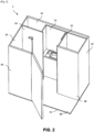
- the fitting module of a system 1 for the interior fitting of a vehicle comprises a first partition 10 which has dimensions adapted to allow a separation between a driving position and the loading area of the vehicle.
- the first partition 10 further comprises a central passage 11.
- the central passage 11 is preferably arranged to allow access, from the fitting module, to the driving position and vice versa.
- the second and third partitions 20, 30 of the development module are substantially perpendicular to the first partition 10.
- the fourth and fifth partitions 40, 50 are respectively positioned substantially perpendicular to the second and third partitions 20, 30. More particularly, the first, second and fourth partitions 10, 20, 40 form a first reception area. The first, second and fourth partitions 10, 20, 40 which form the first reception area thus have dimensions adapted to a first piece of furniture 25.
- first, third and fifth partitions 10, 30, 50 form a second reception space of dimensions adapted to a second piece of furniture 35.
- the first transverse guide means of the fitting module is positioned between the second partition 20 and the central passage 11 and the second transverse guide means is positioned between the third partition 30 and the central passage 11.
- first partition 10 and the first and second transverse guide means are adapted to allow the fixing of the first or second furniture element 25, 35. Once fixed on the first and second transverse guide means, the furniture elements 25, 35 can undergo a translational movement along the axis of the transverse guide means.
- first partition 10 and each transverse guide means are arranged so that the first or second furniture element 25, 35 passes from a first folded configuration, in which the first furniture element 25 or the second furniture element 35 is positioned between the central passage 11 and the second or third partition 20, 30, to a second deployed configuration, in which the first furniture element 25 or the second furniture element 35 fills the central passage 11.
- the first furniture element 25 can be arranged to be able to switch to the deployed configuration when the second furniture element 35 is in the folded position and vice versa. This thus makes it possible to use the first or second furniture element 25, 35 only when the furniture element that is not being used is in the folded configuration.
- the second transverse guide means can be positioned on the upper part of the first partition 10, between the second and third partitions 20, 30, adjacent to the first partition 10, and the central passage 11.
- first and second transverse guide means may be equipped with locking devices in order to allow the transverse guide means to be blocked in different positions.
- first and second transverse guide means may comprise a system of stops with end-of-travel dampers.
- first and second transverse guide means may respectively correspond to a roller or ball guide rail fixed directly to the first partition 10.
- first and second transverse guide means may correspond to telescopic ball or roller slides which allow total or partial extraction up to 200% of the length of the telescopic slide.
- the first partition 10 may comprise two third transverse guide means respectively adapted to allow the fixing of the first furniture element 25 and the second furniture element 35.
- the two third transverse guide means may be respectively arranged so that the first furniture element 25 and the second furniture element 35 pass from the first folded configuration to the second deployed configuration.
- the third transverse guide means are preferably positioned on the lower part of the first partition 10, between the second and third partitions 20, 30, adjacent to the first partition 10, and the central passage 11.
- the first furniture element 25 may correspond to a cabin equipped with a door, the cabin being arranged to allow, in the deployed configuration, the opening and closing of said door.
- said cabin may comprise a toilet of known type, in particular which can be found in most converted vans.
- the second piece of furniture 35 may correspond to a piece of furniture equipped with a sink and a connection system to a water inlet and outlet.
- the first furniture element 25 can be positioned between the fourth partition 40 and the first partition 10 and the second furniture element 35 can be positioned between the fifth partition 50 and the first partition 10.
- the layout module may comprise a sixth partition 60, as presented in connection with the Figures 1 to 3 , substantially perpendicular to the third partition 30 so that the third, fifth and sixth partitions 30, 50, 60 form a third reception space adapted to accommodate a water inlet and outlet.
- the fifth partition 50 is positioned at a distance from the first partition 10 adapted to the dimensions of the second furniture element 35 and sufficient for the second furniture element 35 to occupy, in the folded configuration, substantially all of the space between the first partition 10 and the fifth partition 50.
- the fifth partition 50 is also used for the formation of the third reception space, thus making it possible to further optimize the available space.
- the invention relates to a system for furnishing a loading area of a vehicle.
- a system for furnishing a loading area of a vehicle.
- a system 1 for the interior arrangement of a vehicle according to the invention and a seating device.
- a loading area of a recreational vehicle preferably a van and/or a van.
- the furnishing system 2 of a loading area of a vehicle comprises a seating device 3 and a system 1 for the interior arrangement of a vehicle according to the invention.
- the furnishing system 2 of a loading area is presented in two parts, the first part P1 is the part intended to be located behind the driving position of the vehicle.
- the second part P2 mainly represented on the Figures 4A t 4B is the part intended to be located at the rear of the vehicle, opposite the driving position.
- the elements that constitute the seating device 3 can be fixed to the support structure 70 arranged to rest on the floor of the loading area of the vehicle.
- the support structure 70 can also comprise a raised structure 71 adapted to match the shape of the wheel arch that is commonly found at the rear of the loading area of certain types of utility vehicles, such as vans, pickup trucks.
- FIG. 4A presents an embodiment of a furnishing system 2 according to the invention which comprises four seating devices 3 positioned, two by two, face to face. Each pair of seating devices 3 is separated by a removable storage element 3-1 arranged so that one side of the removable storage element 3-1 forms an armrest.
- the storage element 3-1 may take a parallelepiped shape and comprise a hollow space serving as storage for various accessories.
- the seating devices 3 are suitable for use when the vehicle is not in motion.
- the seating devices 3 are suitable for use when the vehicle is in motion. Indeed, two of the seating devices positioned face to face can move into a second position, by rotation. In this configuration, the storage element 3-1 can be removed in order to allow a user to sit and position his lower limbs, in place of the storage element 3-1, between a first and a second seating device 3.
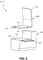
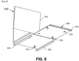
- the seating device 3 comprises a seat 310 comprising a seat 312 on which a plurality of fixing elements 313 are mounted.
- the fastening elements 313 may correspond to studs with a groove, the groove of the stud corresponding to a grooved portion of the stud whose diameter is less than that of the stud (of the non-grooved portion of the stud).
- the seating device 3 further comprises a seat support 320 and a plurality of fixing holes 323 arranged to receive the fixing elements 313.
- the fixing holes 323 are arranged to allow the reception of the fixing elements 313 and to ensure the maintenance of the seat 310 to the seat support 320.
- the fixing holes 323 can be arranged to allow a connection by embedding of the fixing elements 313.
- the fixing holes 323 have a first recess whose diameter is adapted to accommodate the stud with groove.
- the fixing holes 323 can further have a second recess which has a diameter smaller than that of the first recess and which makes it possible to accommodate the grooved part called "groove" of the stud and thus ensure the maintenance of the seat 310 to the seat support 320.
- said seating device comprises a securing/detaching means 330 positioned in the seat support 320.
- the securing/detaching means The attachment/detachment 330 can be integrated into a recess made in the seat support 320. Openings are thus made in the seat support 320 in order to allow the attachment/detachment of the seat 310 to the seat support 320.
- the securing/detaching means 330 comprises a plurality of openings 331 adapted to allow the passage of the fixing elements 313 and is further arranged to allow reversible fixing between the seat 310 and the seat support 320. More particularly, the securing/detaching means 330 can be arranged to allow adequate positioning between the fixing elements 313 and the fixing orifices 323 and thus ensure their connections.
- the openings 331 are arranged to allow the reception of the fixing elements 313 and to ensure the maintenance of the seat 310 on the seat support 320.
- the openings 331 can be arranged to allow a connection by embedding of the fixing elements 313.
- the openings 331 have a recess whose diameter is adapted to accommodate the stud with groove.
- the application of a horizontal force by means of securing/detaching 330 in a first direction allows the connection between the fixing elements 313 and the fixing orifices 323, while the application of a horizontal force by means of securing/detaching 330 in a second direction, opposite to the first direction, allows the detachment between the fixing elements 313 and the fixing orifices 323.
- the fixing elements 313 are studs with a groove
- the application of a horizontal force by means of securing/detaching 330 in a first direction makes it possible to accommodate the grooved part called “groove” of the stud in the second recess and thus ensure the maintenance of the seat 310 on the seat support 320.
- the securing/detaching means 330 may comprise a gripping means 332 allowing a user to apply a force by pulling or pushing in a first or second direction, the securing/detaching means 330.
- the gripping means 332 may take the form of a vertical rim extending along one side of the securing/detaching means 330.
- the seat support 320 may comprise positioning supports 324, 325 on which the securing/detaching means 330 may be mounted, for example in a recess made in the seat support 320, so as to be able to slide.
- the positioning supports 324, 325 advantageously have dimensions adapted to the securing/detaching means 330.
- the seat 310 may comprise a backrest 311 connected to the seat 312.
- the seat 310 may further be arranged to be fixed to the seat support 320 according to a first position in which the plurality of fixing holes 323 coincide with at least two fixing elements 31.3 and according to a second position in which the plurality of fixing holes 323 coincide with at least two other fixing elements 313.
- fixing holes 323 can be positioned on the seat support 320 in such a way that the seat 310 can be fixed to the seat support 320 in different positions by rotation of said seat.
- the seat 310 may further be arranged to be fixed to the seat support 320 in a first position in which the backrest 311 is substantially perpendicular to a longitudinal axis of the first partition 10.
- the seat 310 may further be arranged to be fixed to the seat support 320 in a second position in which the backrest 311 is substantially parallel to the longitudinal axis of the first partition 10.
- the furnishing system 2 may comprise a plurality of seating devices 3.
- four seating devices 3 separated, two by two, by a removable storage element 3-1 are represented, the seating devices are positioned in a position in which the backrest 311 is substantially perpendicular to a longitudinal axis of the first partition 10. This position may in particular be used when the vehicle is not moving. Furthermore, in this position, a mattress may be arranged on the seats 312 of the seating devices 3.
- each seating device 3 can comprise a seat belt, of known type, which makes it possible to keep the user's body secured to the seat 310.
- the invention relates to a vehicle comprising a system 1 for interior fittings according to the invention or a furnishing system 2 according to the invention.
- the vehicle may be of the motorized recreational type, such as motor homes, or towable, such as caravans, vans or campers.
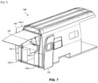
- the vehicle may further comprise, in the rear part, a transparent tailgate 101 and a reversible opening means 102, 103.
- the reversible opening means may be composed of a first and a second swing door 102, 103 as illustrated in figure 7 . Furthermore, the reversible opening means is arranged to move from an open position allowing access to the loading area of the vehicle to a closed position.
- the transparent tailgate 101 is mounted on a frame of the rear part of the vehicle.
- the transparent tailgate 101 is arranged to pass from a first deployed configuration, when the reversible opening means 102, 103 is in the open position, to a second folded configuration, when the reversible opening means 102, 103 is in the closed position.
- the transparent tailgate 101 In the deployed configuration, the transparent tailgate 101 is substantially parallel to a longitudinal axis of the vehicle 100, while in the folded configuration, the transparent tailgate 101 is substantially perpendicular to a longitudinal axis of the vehicle 100.
- the vehicle 100 may comprise at least one tailgate cylinder 105-1, 105-2, the pressure of which allows the transparent tailgate 101 to remain in the deployed configuration.
- the frame on which the transparent tailgate 101 is mounted may be a body part of the vehicle 100.
- the frame can be adapted to be fixed directly to the floor of the vehicle and on a body part of the vehicle.
- the frame may be composed of two longitudinal profiles 104-1, 104-2, fixed to the floor of the vehicle, and extending over all or part of the height of the reversible opening means 102, 103.
- a tailgate cylinder 105-1, 105-2 may be fixed on each longitudinal profile 104-1, 104-2.
- the upper part of the transparent tailgate 101 may further be coupled to a transverse profile 104-3, connecting the two longitudinal profiles, by at least one connecting element allowing the transition from the folded configuration to the deployed configuration.
- the invention may be the subject of numerous variants and applications other than those described above.
- the different structural and functional features of each of the implementations described above should not be considered as combined and/or closely and/or inextricably linked to each other, but on the contrary as simple juxtapositions.
- the structural and/or functional features of the different embodiments described above may be the subject in whole or in part of any different juxtaposition or any different combination.
Landscapes
- Engineering & Computer Science (AREA)
- Health & Medical Sciences (AREA)
- Public Health (AREA)
- Mechanical Engineering (AREA)
- Transportation (AREA)
- Epidemiology (AREA)
- General Health & Medical Sciences (AREA)
- Vehicle Step Arrangements And Article Storage (AREA)
- Vehicle Interior And Exterior Ornaments, Soundproofing, And Insulation (AREA)
Applications Claiming Priority (1)
| Application Number | Priority Date | Filing Date | Title |
|---|---|---|---|
| FR2306592A FR3150158B1 (fr) | 2023-06-23 | 2023-06-23 | Systéme pour l’aménagement interieur d’un véhicule, systéme d’ameublement d’une zone de chargement d’un véhicule et véhicule associé |
Publications (3)
| Publication Number | Publication Date |
|---|---|
| EP4480751A1 true EP4480751A1 (de) | 2024-12-25 |
| EP4480751C0 EP4480751C0 (de) | 2026-01-28 |
| EP4480751B1 EP4480751B1 (de) | 2026-01-28 |
Family
ID=88290634
Family Applications (1)
| Application Number | Title | Priority Date | Filing Date |
|---|---|---|---|
| EP23315331.1A Active EP4480751B1 (de) | 2023-06-23 | 2023-08-30 | System zur inneneinrichtung eines fahrzeugs, einrichtung zur einrichtung einer ladefläche eines fahrzeugs und fahrzeug |
Country Status (4)
| Country | Link |
|---|---|
| US (1) | US12172566B1 (de) |
| EP (1) | EP4480751B1 (de) |
| CA (1) | CA3235695A1 (de) |
| FR (1) | FR3150158B1 (de) |
Citations (4)
| Publication number | Priority date | Publication date | Assignee | Title |
|---|---|---|---|---|
| AU2010202803B2 (en) * | 2009-07-29 | 2012-02-16 | Fisher, Philip Graeme | Accommodation Unit |
| CN209225083U (zh) * | 2018-12-24 | 2019-08-09 | 江西趣蜂专用车装备有限公司 | 用于旅居车的拓展卫生间 |
| KR102253177B1 (ko) | 2019-01-18 | 2021-05-18 | (주)나인인디에어 | 가변형 욕실을 구비한 캠핑카 |
| KR20220146884A (ko) | 2021-04-26 | 2022-11-02 | 김재휘 | 접이식 칸막이 구조의 캠핑카 가변식 화장실 |
Family Cites Families (11)
| Publication number | Priority date | Publication date | Assignee | Title |
|---|---|---|---|---|
| CA2149110A1 (en) * | 1995-05-10 | 1996-11-11 | Jacobus N. Hanemaayer | Swingable bathroom wash basin and collapsible counter top assembly for a recreational vehicule |
| US6623058B1 (en) * | 2000-09-06 | 2003-09-23 | Alfa Leisure, Inc. | Securing mechanism for recreational vehicle slide outs |
| US6637804B1 (en) * | 2001-10-30 | 2003-10-28 | Alfa Leisure, Inc. | Recreational vehicle with walk through slide out |
| EP1318049A3 (de) * | 2001-12-10 | 2004-08-04 | Hobby-Wohnwagenwerk Ing. Harald Striewski GmbH | Nasszelle, insbesondere zur Verwendung in Wohnwagen oder Reisemobilen |
| US12082755B2 (en) * | 2016-02-17 | 2024-09-10 | Tetravan LLC | Folding shower stalls |
| DE102017212693A1 (de) * | 2017-06-14 | 2018-12-20 | Volkswagen Aktiengesellschaft | Nasszelle und Fahrzeug oder Gebäude mit zumindest einer derartigen Nasszelle sowie Duschkopf, Waschbecken und/oder Spiegelelement |
| US10232806B1 (en) * | 2017-11-07 | 2019-03-19 | Zsuzsanna Feher | Sliding toilet enclosure |
| US11884200B2 (en) * | 2021-06-28 | 2024-01-30 | II Peter J. Tezza | Modular pop-up semi-dry bathroom |
| WO2023059745A1 (en) * | 2021-10-09 | 2023-04-13 | Itty Atcravi | Motorhome with expandable bathroom |
| CN113771725A (zh) * | 2021-10-09 | 2021-12-10 | 黄燕军 | 一种自带游艇的通勤旅居两用房车 |
| US20230286594A1 (en) * | 2022-03-11 | 2023-09-14 | Robert Culpi | Vehicle interior furnishings and related accessories and fixtures |
-
2023
- 2023-06-23 FR FR2306592A patent/FR3150158B1/fr active Active
- 2023-08-30 EP EP23315331.1A patent/EP4480751B1/de active Active
-
2024
- 2024-04-18 CA CA3235695A patent/CA3235695A1/fr active Pending
- 2024-05-10 US US18/660,894 patent/US12172566B1/en active Active
Patent Citations (4)
| Publication number | Priority date | Publication date | Assignee | Title |
|---|---|---|---|---|
| AU2010202803B2 (en) * | 2009-07-29 | 2012-02-16 | Fisher, Philip Graeme | Accommodation Unit |
| CN209225083U (zh) * | 2018-12-24 | 2019-08-09 | 江西趣蜂专用车装备有限公司 | 用于旅居车的拓展卫生间 |
| KR102253177B1 (ko) | 2019-01-18 | 2021-05-18 | (주)나인인디에어 | 가변형 욕실을 구비한 캠핑카 |
| KR20220146884A (ko) | 2021-04-26 | 2022-11-02 | 김재휘 | 접이식 칸막이 구조의 캠핑카 가변식 화장실 |
Also Published As
| Publication number | Publication date |
|---|---|
| EP4480751C0 (de) | 2026-01-28 |
| US20240424975A1 (en) | 2024-12-26 |
| FR3150158B1 (fr) | 2025-05-23 |
| EP4480751B1 (de) | 2026-01-28 |
| US12172566B1 (en) | 2024-12-24 |
| CA3235695A1 (fr) | 2025-06-12 |
| FR3150158A1 (fr) | 2024-12-27 |
Similar Documents
| Publication | Publication Date | Title |
|---|---|---|
| CA2492529A1 (fr) | Module de cabine d'aeronef pour passagers | |
| WO2010029223A1 (fr) | Systeme de tablette extensible de siege, module de siege et aeronef comprenant un tel systeme | |
| FR2935684A1 (fr) | Systeme de sieges pour passager integrant un meuble multi-fonctionnel, et aeronef comprenant un tel systeme | |
| EP3019401B1 (de) | Vorrichtung zur verbesserung des komforts von passagieren eines transportmittels ohne wechsel von dessen personenbeförderungskapazität | |
| EP4480751B1 (de) | System zur inneneinrichtung eines fahrzeugs, einrichtung zur einrichtung einer ladefläche eines fahrzeugs und fahrzeug | |
| FR2821035A1 (fr) | Agencement de coffre d'un vehicule automobile | |
| EP1927500A2 (de) | Fahrzeuginnenraum, Sitzgestell und Montageverfahren | |
| FR2943961A1 (fr) | Vehicule automobile du type camping-car | |
| FR2889122A1 (fr) | Agencement de trois sieges a l'arriere d'un vehicule | |
| FR2872114A1 (fr) | Agencement pour la fixation d'un element de rangement sous un pavillon d'un habitacle de vehicule | |
| FR2972151A1 (fr) | Vehicule automobile avec amenagement interieur modulable | |
| EP0704340A1 (de) | Klappsitz für Fahrzeuge | |
| FR3163325A1 (fr) | Systéme pour l’aménagement interieur d’un véhicule, systéme d’ameublement d’une zone de chargement d’un véhicule et véhicule associé | |
| FR2858953A1 (fr) | Agencement pour un vehicule automobile comportant des sieges arriere deployables sur le plancher | |
| EP2263913B1 (de) | Wohnfahrzeug mit einer zentral platzierten Sitzbank und zwei seitlichen Sitzen | |
| FR2765164A1 (fr) | Dispositif d'amenagement d'un vehicule du type monospace | |
| FR2458461A1 (fr) | Cloison mobile pour separation de classes dans des avions commerciaux | |
| FR2890611A1 (fr) | Dispositif d'agencement modulable de sieges dans un vehicule automobile | |
| FR2923762A1 (fr) | Equipement articule pour siege de vehicule automobile, en particulier accoudoir | |
| EP4454967A1 (de) | Anordnung für ein schienenfahrzeug und entsprechendes fahrzeug | |
| FR3147533A1 (fr) | Véhicule comprenant une console centrale modulable | |
| FR3148962A1 (fr) | véhicule comprenant une console centrale modulable | |
| FR2877288A1 (fr) | Tablette escamotable | |
| FR3148961A1 (fr) | véhicule comprenant une console centrale modulable | |
| FR3158934A1 (fr) | caravane extensible pour vélo |
Legal Events
| Date | Code | Title | Description |
|---|---|---|---|
| PUAI | Public reference made under article 153(3) epc to a published international application that has entered the european phase |
Free format text: ORIGINAL CODE: 0009012 |
|
| STAA | Information on the status of an ep patent application or granted ep patent |
Free format text: STATUS: THE APPLICATION HAS BEEN PUBLISHED |
|
| AK | Designated contracting states |
Kind code of ref document: A1 Designated state(s): AL AT BE BG CH CY CZ DE DK EE ES FI FR GB GR HR HU IE IS IT LI LT LU LV MC ME MK MT NL NO PL PT RO RS SE SI SK SM TR |
|
| STAA | Information on the status of an ep patent application or granted ep patent |
Free format text: STATUS: REQUEST FOR EXAMINATION WAS MADE |
|
| 17P | Request for examination filed |
Effective date: 20250623 |
|
| GRAP | Despatch of communication of intention to grant a patent |
Free format text: ORIGINAL CODE: EPIDOSNIGR1 |
|
| STAA | Information on the status of an ep patent application or granted ep patent |
Free format text: STATUS: GRANT OF PATENT IS INTENDED |
|
| RIC1 | Information provided on ipc code assigned before grant |
Ipc: B60P 3/34 20060101AFI20250714BHEP Ipc: B60P 3/36 20060101ALI20250714BHEP Ipc: B60R 15/00 20060101ALN20250714BHEP |
|
| INTG | Intention to grant announced |
Effective date: 20250818 |
|
| GRAS | Grant fee paid |
Free format text: ORIGINAL CODE: EPIDOSNIGR3 |
|
| GRAA | (expected) grant |
Free format text: ORIGINAL CODE: 0009210 |
|
| STAA | Information on the status of an ep patent application or granted ep patent |
Free format text: STATUS: THE PATENT HAS BEEN GRANTED |
|
| AK | Designated contracting states |
Kind code of ref document: B1 Designated state(s): AL AT BE BG CH CY CZ DE DK EE ES FI FR GB GR HR HU IE IS IT LI LT LU LV MC ME MK MT NL NO PL PT RO RS SE SI SK SM TR |
|
| REG | Reference to a national code |
Ref country code: CH Ref legal event code: F10 Free format text: ST27 STATUS EVENT CODE: U-0-0-F10-F00 (AS PROVIDED BY THE NATIONAL OFFICE) Effective date: 20260128 Ref country code: GB Ref legal event code: FG4D Free format text: NOT ENGLISH |
|
| REG | Reference to a national code |
Ref country code: DE Ref legal event code: R096 Ref document number: 602023011294 Country of ref document: DE |
|
| REG | Reference to a national code |
Ref country code: IE Ref legal event code: FG4D Free format text: LANGUAGE OF EP DOCUMENT: FRENCH |
|
| U01 | Request for unitary effect filed |
Effective date: 20260212 |
|
| U07 | Unitary effect registered |
Designated state(s): AT BE BG DE DK EE FI FR IT LT LU LV MT NL PT RO SE SI Effective date: 20260217 |