EP4454967A1 - Anordnung für ein schienenfahrzeug und entsprechendes fahrzeug - Google Patents
Anordnung für ein schienenfahrzeug und entsprechendes fahrzeug Download PDFInfo
- Publication number
- EP4454967A1 EP4454967A1 EP24171602.6A EP24171602A EP4454967A1 EP 4454967 A1 EP4454967 A1 EP 4454967A1 EP 24171602 A EP24171602 A EP 24171602A EP 4454967 A1 EP4454967 A1 EP 4454967A1
- Authority
- EP
- European Patent Office
- Prior art keywords
- face
- berth
- headrest
- convertible unit
- convertible
- Prior art date
- Legal status (The legal status is an assumption and is not a legal conclusion. Google has not performed a legal analysis and makes no representation as to the accuracy of the status listed.)
- Pending
Links
Images

Classifications
-
- B—PERFORMING OPERATIONS; TRANSPORTING
- B61—RAILWAYS
- B61D—BODY DETAILS OR KINDS OF RAILWAY VEHICLES
- B61D1/00—Carriages for ordinary railway passenger traffic
- B61D1/06—Carriages for ordinary railway passenger traffic with multiple deck arrangement
- B61D1/08—Carriages for ordinary railway passenger traffic with multiple deck arrangement of sleeping carriages
-
- B—PERFORMING OPERATIONS; TRANSPORTING
- B60—VEHICLES IN GENERAL
- B60P—VEHICLES ADAPTED FOR LOAD TRANSPORTATION OR TO TRANSPORT, TO CARRY, OR TO COMPRISE SPECIAL LOADS OR OBJECTS
- B60P3/00—Vehicles adapted to transport, to carry or to comprise special loads or objects
- B60P3/32—Vehicles adapted to transport, to carry or to comprise special loads or objects comprising living accommodation for people, e.g. caravans, camping, or like vehicles
- B60P3/36—Auxiliary arrangements; Arrangements of living accommodation; Details
- B60P3/38—Sleeping arrangements, e.g. living or sleeping accommodation on the roof of the vehicle
-
- B—PERFORMING OPERATIONS; TRANSPORTING
- B61—RAILWAYS
- B61D—BODY DETAILS OR KINDS OF RAILWAY VEHICLES
- B61D31/00—Sleeping accommodation
-
- B—PERFORMING OPERATIONS; TRANSPORTING
- B61—RAILWAYS
- B61D—BODY DETAILS OR KINDS OF RAILWAY VEHICLES
- B61D33/00—Seats
Definitions
- the present invention relates to an assembly for a vehicle, in particular for a railway vehicle.
- the present invention also relates to a car for a railway vehicle comprising such an assembly.
- the present invention finds, in particular, applications for so-called “night trains”.
- Such night trains commonly include berths adapted to accommodate a passenger in a lying position.
- installations convertible between a seat position and a couchette position comprise two separate seats each having a seat surface and two separate backrests each associated with a seat structure.
- these installations comprise a support, one of the faces of which is integral with the rear faces of the two backrests and the other face of which is integral with a mattress.
- An aim of the invention is to overcome the aforementioned drawbacks by proposing an assembly for a railway vehicle which is simpler to assemble and improves passenger comfort.
- the invention also relates to a carriage for a railway vehicle comprising at least one compartment and an assembly as described above, the assembly being arranged in said compartment.
- FIG. 1 schematically and in perspective illustrates a part of a railway car 10 of a railway vehicle.
- a longitudinal direction X corresponding to a direction of advance of the railway vehicle a transverse direction Y, substantially perpendicular to the longitudinal direction X and an elevation direction Z, substantially perpendicular to the longitudinal X and transverse Y directions, are defined.
- a dimension of a member measured along the longitudinal direction X is called width and a dimension of a member measured along the transverse direction Y is called length.
- a member A arranged above a member B means that member A has a greater elevation than member B along the elevation direction Z.
- the railway car 10 hereinafter “car 10”, comprises at least one compartment 12 and an assembly 14 arranged in the compartment 12.
- Compartment 12 has an interior volume delimited by at least four partition walls and a floor 18.
- first partition wall 16 1 The four partition walls are hereinafter referred to as “first partition wall 16 1 ”, “second partition wall 16 2 ”, “third partition wall 16 3 ” and “fourth partition wall”.
- the fourth partition wall has been omitted in the figure 1 .
- the partition walls extend substantially in the elevation direction Z.
- the partition walls are approximately perpendicular to each other.
- the first partition wall 16 1 and the second partition wall 16 2 are substantially parallel to each other and the third partition wall 16 3 and the fourth partition wall are substantially parallel to each other.
- Floor 18 extends substantially perpendicular to the elevation direction Z.
- the assembly 14 comprises at least one convertible unit and, in this particular example, at least one upper bunk arranged above the convertible unit, referred to as a "combined convertible unit and upper bunk".
- the assembly 14 further comprises a convertible unit support and an upper bunk support.
- the assembly comprises at least one headrest and a ladder.
- the assembly comprises two convertible units, hereinafter referred to as “first convertible unit 21” and “second convertible unit 22", two convertible unit supports, hereinafter referred to as “first convertible unit support 24" and “second convertible unit support 26", at least two upper bunks, hereinafter referred to as “first upper bunk 31” and “second upper bunk 32", two headrests, hereinafter referred to as “first headrest 41” and “second headrest 42”, and two ladders, hereinafter referred to as “first ladder 44" and "second ladder 46".
- first convertible unit 21 and the second convertible unit 22 are analogous.
- Each convertible unit 21, 22 comprises a seat structure 48 and a backrest 50.
- each convertible unit 21, 22 comprises a central armrest 52.
- each convertible unit 21, 22 is movable between a PS seat position and a PC sleeper position.
- each convertible unit 21, 22 delimits at least two seats.
- the first convertible unit 21 is shown in the PS seat position and delimits two seats 21S.
- each convertible unit 21, 22 defines a berth, called a "lower berth".
- the first convertible unit 21 defines a first lower berth (not visible in the figure 1 ) and the second convertible unit 22 defines a second lower berth 22C, visible on the figure 1 .
- the seat structure 48 has at least two seat surfaces 54 and a reception area 56 for the central armrest 52 in the PC reclining position.
- the seating surfaces 54 are separated from each other in the transverse direction Y. In other words, the seating surfaces 54 are distinct.
- the seating surfaces 54 are separated from each other by the reception area 56 of the central armrest 52.
- Each seating surface 54 has, in the example illustrated in the figure 1 , a hollow shape.
- the reception area 56 is a hollow area provided in the seating structure 48 of this convertible unit 21, 22.
- the reception area 56 has a shape complementary to the central armrest 52 so as to accommodate the central armrest 52 in the PC berth position of the corresponding convertible unit 21, 22.
- the seating structure 48 of each convertible unit 21, 22 comprises a central console (not shown in the figures) arranged between the two seating surfaces 54.
- the seat structure 48 is in the form of a single piece.
- the backrest 50 has a first face 50A and a second face 50B opposite the first face 50A.
- the first face 50A and the second face 50B have distinct shapes.
- the first face 50A has, for each seating surface 54, a support surface 58 for a passenger's back.
- the first face 50A has a fixing surface 60 for the central armrest 52.
- Each support surface 58 is intended to receive at least part of the back of a passenger seated on the associated seating surface 54.
- the support surfaces 58 are aligned along the transverse direction Y.
- the bearing surfaces 58 are separated from each other.
- the backrest 50 has two support surfaces 58 separated from each other by the fixing surface 60 of the central armrest 52.
- each support surface 58 has a shape complementary to the associated seat surface 54.
- each bearing surface 58 has at least a partially curved shape.
- the fixing surface 60 of the central armrest 52 is arranged between the two support surfaces 58 and intended to receive the central armrest 52.
- the second face 50B of the backrest 50 is substantially flat and has a shape distinct from the first face 50A of the backrest 50.
- the second face 50B of the backrest 50 is intended to receive a passenger in the lying position in the berth position PC of this convertible unit 21, 22.
- the backrest 50 includes a mattress 62.
- the backrest 50 is rotatable about an axis of rotation R50 relative to the seat structure 48 between the seat position PS and the berth position PC of this convertible unit 21, 22.
- the seat structure 48 and the backrest 50 are mechanically connected to each other by a fixing mechanism (not visible in the figures) allowing the rotation of the backrest 50 around the axis of rotation R50 relative to the seat structure 48.
- the central armrest 52 has a receiving surface adapted to receive an elbow and/or a forearm of a passenger seated on one or other of the seating surfaces 54.
- the central armrest 52 is pivotally mounted on the fixing surface 60 of the first face 50A of the backrest 50 about a pivot axis by means of a pivot connection.
- the pivot axis is substantially parallel, in this example, to the transverse direction Y.
- each central armrest 52 is pivotally mounted about the pivot axis relative to the first face 50A of the backrest 50 between an armrest position and a retracted position.
- the receiving surface of the center armrest 52 is configured to receive the elbow and/or forearm of a passenger. Furthermore, the receiving surface of the center armrest 52 extends substantially perpendicular to the attachment surface 60.
- Each central armrest 52 is adapted to be arranged in the armrest position in the PS seat position of the convertible unit 21, 22 to which this central armrest 52 belongs.
- each central armrest 52 In the folded position, the receiving surface of each central armrest 52 is not configured to receive the elbow and/or forearm of a passenger. Furthermore, in the folded position, the receiving surface of each central armrest 52 is arranged against the fixing surface 60 of the backrest 50 of the convertible unit 21, 22 to which this central armrest 52 belongs.
- each seating surface 54 and the support surface 58 associated with this seating surface 54 delimit between them at least two seats. As shown in the figure 1 , each seating surface and the associated support surface of the first convertible unit delimits a 21S seat.
- each seat surface 54 and each associated support surface 58 form substantially an angle equal to 90°.
- the second face 50B of the backrest 50 is configured to receive a passenger in the lying position.
- the second face 50B of the backrest 50 of this convertible unit 21, 22 extends substantially perpendicular to the elevation direction Z.
- the second face 50B of the backrest 50 extends in a lower berth extension direction.
- the lower berth extension direction defines the direction along which a passenger is able to lie on the second face 50B of the backrest 50. Only the lower berth extension direction D22C of the second lower berth 22C is visible on the figure 1 .
- each seating surface 54 is at least partly in contact with the associated support surface 58 of the first face 50A of the backrest 50.
- each seating surface 54 is fully in contact with the associated support surface 58.
- each support surface 58 is fitted into the associated seat surface 54.
- the central armrest 52 of this convertible unit 21, 22 is in the folded position and arranged in the reception area 56 of the seat structure 48 of this convertible unit 21, 22.
- the first convertible unit 21 is arranged on the first convertible unit support 24 and the second convertible unit 22 is arranged on the second convertible unit support 26.
- Each convertible unit support 24, 26 has a substantially “L” shaped section in a plane perpendicular to the transverse direction Y.
- Each convertible unit support 24, 26 extends between a corresponding partition wall 16 1 , 16 2 and the floor 18.
- the first upper berth 31 is associated with the first convertible unit 21 and the second berth 32 is associated with the second convertible unit 22.
- the associated upper bunk 31, 32 is superimposed on this convertible unit 21, 22 in the elevation direction Z.
- each upper berth 31, 32 is arranged above the associated convertible unit 21, 22 such that in the PS seat position of that convertible unit 21, 22, a passenger can sit on one of the seating areas 54 of the associated convertible unit without interfering with the upper berth 31, 32.
- Each upper bunk 31, 32 has a deployed configuration as seen in the figure 1 .
- each upper bunk 31, 32 is fixed.
- each upper bunk 31, 32 is capable of accommodating a passenger in the lying position.
- each upper bunk 31, 32 extends along an upper bunk extension direction D31, D32.
- the upper bunk 31, 32 extension direction D31, D32 is substantially parallel to the transverse direction Y.
- Each upper bunk 31, 32 comprises at least one mattress support 34 and at least one mattress 64.
- the mattress support 34 of the first upper bunk 31 and the mattress support 34 of the second upper bunk 32 are connected, so as to form a single mattress support 34.
- the single mattress support 34 is capable of supporting both the mattresses 64 of the first upper bunk 31 and the second upper bunk 32.
- the single upper bunk support 34 extends for example between the first partition wall 16 1 and the second partition wall 16 2 .
- the mattress 64 is intended to accommodate a passenger in the lying position.
- Each headrest 41, 42 is associated with a respective convertible unit 21, 22.
- the associated headrest 41, 42 is intended to provide support for the head of a passenger seated on each seating area 54 of this convertible unit 21, 22 in the seat position PS.
- Such a headrest 41, 42 and such a convertible unit 21, 22 are hereinafter referred to as “associated headrest 41, 42 and convertible unit 21, 22”.
- the first headrest 41 is associated with the first convertible unit 21 and the second headrest 42 is associated with the second convertible unit 22.
- the first headrest 41 is arranged between the first convertible unit 21 and the first upper berth 31.
- the first headrest 41 is fixed to the first partition wall 16 1 .
- the second headrest 42 is arranged between the second convertible unit 22 and the second upper berth 32.
- the second headrest 42 is fixed to the second partition wall 16 2 .
- first headrest 41 and the second headrest 42 are structurally similar.
- Each headrest 41, 42 defines at least one reception area 66 for the head of a passenger seated on a seating surface 54 of the associated convertible unit 21, 22 in the PS seat position.
- each headrest 41, 42 comprises a single rigid structure covered with padding.
- the rigid structure has, for example, a “U” shape in section along a plane perpendicular to the transverse direction Y.
- the headrest 41, 42 comprises a plurality of rigid structures each covered by a filling.
- the first ladder 44 and the second ladder 46 are associated with the first upper bunk 31, respectively with the second upper bunk 32.
- Each ladder 44, 46 is rotatably mounted on the third partition wall 16 3 about the elevation direction Z.
- Each ladder 44, 46 is rotatable between a useful configuration CU and a rest configuration CR relative to the associated upper berth 31, 32.
- each ladder 44, 46 is connected by a pivot connection to the third partition wall 16 3 .
- each ladder 44, 46 allows a passenger to reach the associated upper bunk 31, 32.
- the ladder 44, 46 extends substantially perpendicular to the third partition wall 16 3 .
- the ladder 44, 46 does not allow a passenger to reach the associated upper bunk 31, 32.
- the ladder 44, 46 extends substantially against the third partition wall 16 3 .
- one or more of the convertible units 21, 22 includes a convertible armrest (not visible in the figures).
- the convertible armrest is, for illustration purposes, movable between an armrest position and a headboard position.
- the convertible armrest is movable in translation in the elevation direction Z relative to the seat structure 48 between the armrest position and the headboard position.
- the convertible armrest comprises, for example, a panel and a surface for receiving an elbow and/or a forearm of a passenger seated on one of the seating surfaces 54 of the seating structure 48 of the convertible unit 21, 22.
- the panel is substantially planar and extends primarily along the Z elevation direction.
- the receiving surface comprises at least a portion of an upper face of the panel.
- the receiving surface of the convertible armrest is adapted to receive the elbow and/or forearm of a passenger seated on one of the seating surfaces 54 of the convertible unit 21, 22.
- the panel In the headboard position, the panel forms a headboard for the lower bunk 22C.
- the first convertible unit 21 is in the PS seat position and the first ladder 44 is in the CU useful configuration.
- the reception areas 66 of the first headrest 41 associated with the first convertible unit 21 are suitable for receiving the heads of passengers seated on the seating surfaces 54 of the first convertible unit 21.
- the backrest 50 of the first convertible unit 21 is rotated along the rotation axis R50 towards the seat structure 48 until each support surface 58 of the first face 50A of the backrest 50 is in contact with the corresponding seat surface 54 of the seat structure 48.
- the first convertible unit 21 defines the first lower berth and is configured to receive a passenger in the lying position.
- the second planar face 50B of the backrest 50 is configured to receive a passenger in the lying position.
- a passenger uses the first ladder 44 in its useful configuration CU.
- the passenger can pivot the ladder 44 in order to position it from the useful configuration CU to the rest configuration CR.
- the backrest 50 of the first convertible unit 21 is rotated about the axis of rotation R50 in a direction moving the support surfaces 58 away from the associated seat surfaces 54.
- the passenger pivots the first ladder 44 from the rest configuration CR to the useful configuration CU.
- the passenger can use the first ladder 44.
- the assembly 14 according to the invention is particularly simple to assemble and offers increased comfort to the passenger.
- the backrest 50 is lighter than the structure of the prior art comprising two separate backrests, a support and a mattress.
- the handling of the convertible unit 21, 22 for the passage of said convertible unit 21, 22 between the seat positions PS and the berth PC is easier for a passenger.
- a thickness of the mattress 62 can be increased relative to the thickness of the mattress according to the state of the art for a similar size in the longitudinal direction X.
- each support surface 58 has a shape substantially complementary to the shape of the associated seating surface 54, optimal contact is achieved between each support surface 58 and the associated seating surface 54. This makes it possible to obtain optimal comfort for the passenger when the latter is lying on the lower bunk 22C.
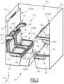
- a second embodiment of a railway vehicle car is described hereinafter with reference to the figure 2 .
- the car 110 according to the second embodiment is described only in contrast to the car 10 of the first embodiment.
- the car 110 according to the second embodiment differs from the car 10 of the first embodiment only in the assembly.
- the assembly 114 according to the second embodiment differs from the assembly 14 according to the first embodiment by the convertible unit supports 121, 122, the upper berths 131, 132 and by each headrest 141, 142.
- the first convertible unit 121 and the second convertible unit 122 are analogous to the first convertible unit 21, respectively to the second convertible unit 22 of the first embodiment.
- each convertible unit 121, 122 comprises a seat structure 148 and a backrest 150 similar to the seat structure 48, respectively to the backrest 50 of the convertible unit 21, 22 of the first embodiment.
- each convertible unit 121, 122 comprises a central armrest 152 similar to the central armrest 52 described in the first embodiment.
- each convertible unit 121, 122 is convertible between a seat position PS and a berth position PC.
- each convertible unit 121, 122 delimits at least two seats (only the two seats 121S delimited by the first convertible unit 121 are visible in the figure 2 ) and in the PC berth position, each convertible unit 121, 122 delimits a lower berth (only the second lower berth 122C delimited by the second convertible unit 122 is visible on the figure 2 ).
- Each convertible unit support 124, 126 has a substantially parallelepiped shape and comprises at least one drawer.
- the upper berths 131, 132 are described only in contrast to the upper berths 31, 32 of the first embodiment.
- Each upper berth 131, 132 is associated, in addition to a convertible unit 121, 122", with a headrest 141, 142.
- Each upper berth 131, 132 and the associated headrest 141, 142 are hereinafter referred to as "upper berth 131, 132 and associated headrest 141, 142".
- this upper berth 131, 132 is arranged above the associated headrest 141, 142.
- the first headrest 141 is associated with the first upper berth 131 and the second headrest 142 is associated with the second upper berth 132.
- Each upper bunk 131, 132 is rotatable along an upper bunk rotation axis R131, R132 between the deployed configuration CD in which it is configured to receive a passenger in the lying position and a retracted configuration CE in which it is inaccessible to a passenger.
- each upper berth 131, 132 is arranged on the associated headrest 141, 142. In other words, at least a portion of each upper berth 131, 132 is arranged in contact with the associated headrest 141, 142.
- each upper bunk 131, 132 is pressed against a corresponding partition wall 16 1 , 16 2 .
- each upper bunk 131, 132 has a normal direction substantially perpendicular to the elevation direction Z.
- Each upper bunk 131, 132 includes a mattress support 134 and a mattress 164.
- each upper bunk 131, 132 is mechanically connected to the associated headrest 141, 142.
- first upper berth 131 is for example mechanically connected to the first headrest 141 and the second upper berth 132 is for example mechanically connected to the second headrest 142.
- each upper berth 131, 132 is connected to the associated headrest 141, 142 by a connection system allowing the rotation of each upper berth 131, 132 around the corresponding rotation axis R131, R132.
- the connecting system also allows a translation of each upper bunk 131, 132 in the longitudinal direction X, so that each upper bunk 131, 132 always remains in contact with the corresponding partition wall 16 1 , 16 2 .
- each upper bunk 131, 132 is mechanically connected to one of the corresponding partition walls 16 1 , 16 2 .
- each upper bunk 131, 132 is connected by the connection system to the corresponding partition wall 16 1 , 16 2 .
- the assembly 114 comprises a system for maintaining the position of each upper bunk 131, 132 in the retracted configuration CE.
- the headrests 141, 142 are only described in contrast to the headrests 41, 42 according to the first embodiment.
- Each headrest 141, 142 is shaped to provide support for the associated upper bunk 131, 132 in the deployed configuration CD.
- Each headrest 141, 142 has an upper face, that is to say, a face facing the associated upper berth 131, 132.
- each headrest 141, 142 has an extension direction parallel to the extension direction of the associated upper berth 131, 132 in its deployed configuration CD. Only the extension direction D132 of the second upper berth 132 is shown in the figure 2 . In the present case, the direction of extension of each upper berth 131, 132 and the direction of extension of the associated headrest 141, 142 are parallel to the transverse direction Y.
- each headrest 141, 142 has a length substantially equal to the length of the associated upper bunk 131, 132.
- At least part of the upper berth 131, 132 associated in the deployed configuration CD rests on this headrest 141, 142.
- each headrest 141, 142 comprises at least one face, called a “contact portion”, configured to be in contact with the associated upper berth 131, 132 in the deployed configuration CD of said upper berth 131, 132.
- the contact portion corresponds to at least a portion of the upper face of the headrest 141, 142.
- the contact portion advantageously corresponds to the entire upper face of the headrest 141, 142.
- a width of at least one zone of said contact portion is greater than or equal to a quarter of the width of the associated upper berth 131, 132, advantageously greater than or equal to a third of the width of the associated upper berth 131, 132.
- the or each zone of the contact portion is hereinafter called the “extended zone”.
- the or each enlarged zone extends in a direction perpendicular to the direction of extension of the associated upper berth 131, 132. In the case illustrated, the or each enlarged zone extends in the longitudinal direction X.
- each headrest 141, 142 has at least a first and a second enlarged zone.
- each headrest 141, 142 has a third enlarged zone.
- the first and second enlarged zones each define one end of this headrest 141, 142.
- FIG. 2 shows the first, second and third enlarged zones 141A, 141B, 141C of the first headrest 141 and only the first enlarged zone 142A of the second headrest 142.
- Each headrest comprises, for each enlarged area, an enlarged portion.
- the enlarged portion corresponds, for example, to a portion of the headrest extending perpendicular to the corresponding enlarged area, and in particular under the corresponding enlarged area. More particularly, the corresponding enlarged area defines the upper face of said enlarged portion.
- the first enlarged zone 141A, 142A of each headrest 141, 142 defines the upper face of a first enlarged portion.
- the second enlarged zone 141B, 142B of each headrest 141, 142 defines the upper face of a second enlarged portion.
- the third enlarged zone 141C, 142C of each headrest 141, 142 defines the upper face of a third enlarged portion.
- Each headrest 141, 142 defines at least one reception zone 166 for the head of a seated passenger.
- the reception zone 166 advantageously extends perpendicular to the widened zones. In the illustrated case, the reception zone 166 extends in the elevation direction Z.
- the first widened portion, the second widened portion and the third widened portion advantageously delimit a reception zone 166 for the head of a passenger.
- the assembly 114 includes at least one movable ladder 170 configured to allow a passenger to climb onto each upper bunk 131, 132.
- the assembly 114 comprises a first scale and a second scale analogous to the first scale 44 and the second scale 46 described in the first embodiment.
- the first upper berth 131 When the first upper berth 131 is in the retracted configuration CE, the first upper berth 131 is rotated along the upper berth rotation axis R131 to position said upper berth 131 in the deployed configuration CD.
- the first upper berth 131 rests on the first headrest 141.
- the first bunk 131 is again rotated along the upper bunk rotation axis R131 towards the first partition wall 16 1 .
- the assembly 114 according to the invention is more robust. Furthermore, thanks to the fact that in the deployed configuration CD the upper bunk 131, 132 rests on the associated headrest 141, 142, this makes it possible to increase the thickness and/or width of the mattress of the upper bunk 131, 132 without harming the support of this upper bunk 131, 132. Thus, the comfort of the passenger is increased.
Landscapes
- Engineering & Computer Science (AREA)
- Mechanical Engineering (AREA)
- Transportation (AREA)
- Health & Medical Sciences (AREA)
- Public Health (AREA)
- Seats For Vehicles (AREA)
Applications Claiming Priority (1)
| Application Number | Priority Date | Filing Date | Title |
|---|---|---|---|
| FR2304070A FR3147995A1 (fr) | 2023-04-24 | 2023-04-24 | Ensemble pour une voiture de véhicule ferroviaire et voiture associée |
Publications (1)
| Publication Number | Publication Date |
|---|---|
| EP4454967A1 true EP4454967A1 (de) | 2024-10-30 |
Family
ID=87571123
Family Applications (1)
| Application Number | Title | Priority Date | Filing Date |
|---|---|---|---|
| EP24171602.6A Pending EP4454967A1 (de) | 2023-04-24 | 2024-04-22 | Anordnung für ein schienenfahrzeug und entsprechendes fahrzeug |
Country Status (2)
| Country | Link |
|---|---|
| EP (1) | EP4454967A1 (de) |
| FR (1) | FR3147995A1 (de) |
Citations (5)
| Publication number | Priority date | Publication date | Assignee | Title |
|---|---|---|---|---|
| PL195854B1 (pl) * | 1999-03-18 | 2007-10-31 | Inst Pojazdow Szynowych Tabor | Zespół fotelowy, zwłaszcza do pojazdów szynowych |
| CZ18310U1 (cs) * | 2008-01-22 | 2008-02-18 | Borcad Cz, S.R.O. | Přestavovací vlakové sedadlo |
| CZ18573U1 (cs) * | 2008-04-25 | 2008-05-20 | Borcad Cz, S. R. O. | Přestavovací lůžková stěna v železničním voze |
| WO2008092382A1 (en) * | 2007-01-29 | 2008-08-07 | Jun Yu | Three-layer berth |
| CN207328463U (zh) * | 2017-06-02 | 2018-05-08 | 中车唐山机车车辆有限公司 | 一种合造车厢及轨道车辆 |
-
2023
- 2023-04-24 FR FR2304070A patent/FR3147995A1/fr active Pending
-
2024
- 2024-04-22 EP EP24171602.6A patent/EP4454967A1/de active Pending
Patent Citations (5)
| Publication number | Priority date | Publication date | Assignee | Title |
|---|---|---|---|---|
| PL195854B1 (pl) * | 1999-03-18 | 2007-10-31 | Inst Pojazdow Szynowych Tabor | Zespół fotelowy, zwłaszcza do pojazdów szynowych |
| WO2008092382A1 (en) * | 2007-01-29 | 2008-08-07 | Jun Yu | Three-layer berth |
| CZ18310U1 (cs) * | 2008-01-22 | 2008-02-18 | Borcad Cz, S.R.O. | Přestavovací vlakové sedadlo |
| CZ18573U1 (cs) * | 2008-04-25 | 2008-05-20 | Borcad Cz, S. R. O. | Přestavovací lůžková stěna v železničním voze |
| CN207328463U (zh) * | 2017-06-02 | 2018-05-08 | 中车唐山机车车辆有限公司 | 一种合造车厢及轨道车辆 |
Also Published As
| Publication number | Publication date |
|---|---|
| FR3147995A1 (fr) | 2024-10-25 |
Similar Documents
| Publication | Publication Date | Title |
|---|---|---|
| EP2219945B1 (de) | Optimiertes flugzeugkabinenlayout | |
| EP3601044B1 (de) | Individuelle flugzeugpassagiere sitzanordnung mit bildschirmstützen, die eine trennwand bilden | |
| EP1707486B1 (de) | Möbelstück für Fahrzeuge, insbesondere für Flugzeuge | |
| FR2998544A1 (fr) | Dossier de siege d'aeronef comprenant une colonne structurale portant des dispositifs transversaux de support de l'occupant | |
| FR2804912A1 (fr) | Systeme d'agencement modulable des sieges dans un vehicule automobile | |
| FR3099100A1 (fr) | Elément de garnissage modulable | |
| BE527162A (fr) | Siège avec accoudoir escamotable | |
| FR2888541A1 (fr) | Banquette arriere de vehicule automobile | |
| FR2885569A1 (fr) | Siege de vehicule automobile equipe d'accoudoirs | |
| EP3944985A1 (de) | Fahrzeugsitz | |
| EP3590759B1 (de) | Passagiersitz in einem transportfahrzeug und mit solchen sitzen ausgestattetes transportfahrzeug | |
| EP4454967A1 (de) | Anordnung für ein schienenfahrzeug und entsprechendes fahrzeug | |
| EP3875311A1 (de) | Fahrzeug für den personennahverkehr | |
| EP2018293B1 (de) | Verstaubarer sitz, insbesondere für die dritte sitzreihe | |
| WO2020126681A1 (fr) | Arrangement d'unités de sièges, notamment pour un avion | |
| EP1516776A1 (de) | Sitzanordnung für ein Kraftfahrzeug mit auf dem Fussboden flach ausfaltbaren Hintersitzen | |
| FR2911542A1 (fr) | Dispositif de siege pour vehicule automobile | |
| FR3100170A1 (fr) | Ensemble de sièges comprenant un siège central modulable | |
| FR2916698A1 (fr) | Banquette de vehicule transformable en une surface de couchage constituee en partie par le dossier de la banquette et un panneau monte pivotant sur le dossier, et vehicule correspondant | |
| FR2847211A1 (fr) | Siege de vehicule automobile | |
| FR3039469A1 (fr) | Banquette pour vehicule de transport comprenant un siege d'appoint | |
| FR2844228A1 (fr) | Siege escamotable comportant des butees d'appui en position d'utilisation | |
| WO2024251947A1 (fr) | Arrangement d'unités de siéges et cabine d'avion comportant un tel arrangement d'unités de siéges | |
| EP4580942A1 (de) | Induktionsladegehäuse für einen sitz mit einer querhaltevorrichtung | |
| FR3161158A1 (fr) | Extension d’appui-tête pour un siège de véhicule |
Legal Events
| Date | Code | Title | Description |
|---|---|---|---|
| PUAI | Public reference made under article 153(3) epc to a published international application that has entered the european phase |
Free format text: ORIGINAL CODE: 0009012 |
|
| STAA | Information on the status of an ep patent application or granted ep patent |
Free format text: STATUS: THE APPLICATION HAS BEEN PUBLISHED |
|
| STAA | Information on the status of an ep patent application or granted ep patent |
Free format text: STATUS: REQUEST FOR EXAMINATION WAS MADE |
|
| AK | Designated contracting states |
Kind code of ref document: A1 Designated state(s): AL AT BE BG CH CY CZ DE DK EE ES FI FR GB GR HR HU IE IS IT LI LT LU LV MC ME MK MT NL NO PL PT RO RS SE SI SK SM TR |
|
| 17P | Request for examination filed |
Effective date: 20241008 |
|
| RBV | Designated contracting states (corrected) |
Designated state(s): AL AT BE BG CH CY CZ DE DK EE ES FI FR GB GR HR HU IE IS IT LI LT LU LV MC ME MK MT NL NO PL PT RO RS SE SI SK SM TR |
|
| GRAP | Despatch of communication of intention to grant a patent |
Free format text: ORIGINAL CODE: EPIDOSNIGR1 |
|
| STAA | Information on the status of an ep patent application or granted ep patent |
Free format text: STATUS: GRANT OF PATENT IS INTENDED |