EP4474514A2 - Schweisskomponente aus stahl unterschiedlicher festigkeit mit aluminiumoder aluminiumlegierungsbeschichtung und verfahren zur herstellung desselben - Google Patents
Schweisskomponente aus stahl unterschiedlicher festigkeit mit aluminiumoder aluminiumlegierungsbeschichtung und verfahren zur herstellung desselben Download PDFInfo
- Publication number
- EP4474514A2 EP4474514A2 EP24208720.3A EP24208720A EP4474514A2 EP 4474514 A2 EP4474514 A2 EP 4474514A2 EP 24208720 A EP24208720 A EP 24208720A EP 4474514 A2 EP4474514 A2 EP 4474514A2
- Authority
- EP
- European Patent Office
- Prior art keywords
- welding
- strength steel
- steel plate
- aluminum
- strength
- Prior art date
- Legal status (The legal status is an assumption and is not a legal conclusion. Google has not performed a legal analysis and makes no representation as to the accuracy of the status listed.)
- Pending
Links
Images


Classifications
-
- B—PERFORMING OPERATIONS; TRANSPORTING
- B23—MACHINE TOOLS; METAL-WORKING NOT OTHERWISE PROVIDED FOR
- B23K—SOLDERING OR UNSOLDERING; WELDING; CLADDING OR PLATING BY SOLDERING OR WELDING; CUTTING BY APPLYING HEAT LOCALLY, e.g. FLAME CUTTING; WORKING BY LASER BEAM
- B23K26/00—Working by laser beam, e.g. welding, cutting or boring
- B23K26/12—Working by laser beam, e.g. welding, cutting or boring in a special environment or atmosphere, e.g. in an enclosure
- B23K26/123—Working by laser beam, e.g. welding, cutting or boring in a special environment or atmosphere, e.g. in an enclosure in an atmosphere of particular gases
-
- B—PERFORMING OPERATIONS; TRANSPORTING
- B23—MACHINE TOOLS; METAL-WORKING NOT OTHERWISE PROVIDED FOR
- B23K—SOLDERING OR UNSOLDERING; WELDING; CLADDING OR PLATING BY SOLDERING OR WELDING; CUTTING BY APPLYING HEAT LOCALLY, e.g. FLAME CUTTING; WORKING BY LASER BEAM
- B23K26/00—Working by laser beam, e.g. welding, cutting or boring
- B23K26/12—Working by laser beam, e.g. welding, cutting or boring in a special environment or atmosphere, e.g. in an enclosure
- B23K26/123—Working by laser beam, e.g. welding, cutting or boring in a special environment or atmosphere, e.g. in an enclosure in an atmosphere of particular gases
- B23K26/125—Working by laser beam, e.g. welding, cutting or boring in a special environment or atmosphere, e.g. in an enclosure in an atmosphere of particular gases of mixed gases
-
- B—PERFORMING OPERATIONS; TRANSPORTING
- B23—MACHINE TOOLS; METAL-WORKING NOT OTHERWISE PROVIDED FOR
- B23K—SOLDERING OR UNSOLDERING; WELDING; CLADDING OR PLATING BY SOLDERING OR WELDING; CUTTING BY APPLYING HEAT LOCALLY, e.g. FLAME CUTTING; WORKING BY LASER BEAM
- B23K26/00—Working by laser beam, e.g. welding, cutting or boring
- B23K26/20—Bonding
- B23K26/21—Bonding by welding
- B23K26/211—Bonding by welding with interposition of special material to facilitate connection of the parts
-
- B—PERFORMING OPERATIONS; TRANSPORTING
- B23—MACHINE TOOLS; METAL-WORKING NOT OTHERWISE PROVIDED FOR
- B23K—SOLDERING OR UNSOLDERING; WELDING; CLADDING OR PLATING BY SOLDERING OR WELDING; CUTTING BY APPLYING HEAT LOCALLY, e.g. FLAME CUTTING; WORKING BY LASER BEAM
- B23K26/00—Working by laser beam, e.g. welding, cutting or boring
- B23K26/20—Bonding
- B23K26/21—Bonding by welding
- B23K26/24—Seam welding
-
- B—PERFORMING OPERATIONS; TRANSPORTING
- B23—MACHINE TOOLS; METAL-WORKING NOT OTHERWISE PROVIDED FOR
- B23K—SOLDERING OR UNSOLDERING; WELDING; CLADDING OR PLATING BY SOLDERING OR WELDING; CUTTING BY APPLYING HEAT LOCALLY, e.g. FLAME CUTTING; WORKING BY LASER BEAM
- B23K26/00—Working by laser beam, e.g. welding, cutting or boring
- B23K26/20—Bonding
- B23K26/21—Bonding by welding
- B23K26/24—Seam welding
- B23K26/242—Fillet welding, i.e. involving a weld of substantially triangular cross section joining two parts
-
- B—PERFORMING OPERATIONS; TRANSPORTING
- B23—MACHINE TOOLS; METAL-WORKING NOT OTHERWISE PROVIDED FOR
- B23K—SOLDERING OR UNSOLDERING; WELDING; CLADDING OR PLATING BY SOLDERING OR WELDING; CUTTING BY APPLYING HEAT LOCALLY, e.g. FLAME CUTTING; WORKING BY LASER BEAM
- B23K26/00—Working by laser beam, e.g. welding, cutting or boring
- B23K26/20—Bonding
- B23K26/32—Bonding taking account of the properties of the material involved
- B23K26/322—Bonding taking account of the properties of the material involved involving coated metal parts
-
- B—PERFORMING OPERATIONS; TRANSPORTING
- B23—MACHINE TOOLS; METAL-WORKING NOT OTHERWISE PROVIDED FOR
- B23K—SOLDERING OR UNSOLDERING; WELDING; CLADDING OR PLATING BY SOLDERING OR WELDING; CUTTING BY APPLYING HEAT LOCALLY, e.g. FLAME CUTTING; WORKING BY LASER BEAM
- B23K26/00—Working by laser beam, e.g. welding, cutting or boring
- B23K26/20—Bonding
- B23K26/32—Bonding taking account of the properties of the material involved
- B23K26/323—Bonding taking account of the properties of the material involved involving parts made of dissimilar metallic material
-
- B—PERFORMING OPERATIONS; TRANSPORTING
- B23—MACHINE TOOLS; METAL-WORKING NOT OTHERWISE PROVIDED FOR
- B23K—SOLDERING OR UNSOLDERING; WELDING; CLADDING OR PLATING BY SOLDERING OR WELDING; CUTTING BY APPLYING HEAT LOCALLY, e.g. FLAME CUTTING; WORKING BY LASER BEAM
- B23K35/00—Rods, electrodes, materials, or media, for use in soldering, welding, or cutting
- B23K35/02—Rods, electrodes, materials, or media, for use in soldering, welding, or cutting characterised by mechanical features, e.g. shape
- B23K35/0255—Rods, electrodes, materials, or media, for use in soldering, welding, or cutting characterised by mechanical features, e.g. shape for use in welding
- B23K35/0261—Rods, electrodes or wires
-
- B—PERFORMING OPERATIONS; TRANSPORTING
- B23—MACHINE TOOLS; METAL-WORKING NOT OTHERWISE PROVIDED FOR
- B23K—SOLDERING OR UNSOLDERING; WELDING; CLADDING OR PLATING BY SOLDERING OR WELDING; CUTTING BY APPLYING HEAT LOCALLY, e.g. FLAME CUTTING; WORKING BY LASER BEAM
- B23K35/00—Rods, electrodes, materials, or media, for use in soldering, welding, or cutting
- B23K35/22—Rods, electrodes, materials, or media, for use in soldering, welding, or cutting characterised by the composition or nature of the material
- B23K35/24—Selection of soldering or welding materials proper
- B23K35/30—Selection of soldering or welding materials proper with the principal constituent melting at less than 1550°C
- B23K35/3053—Fe as the principal constituent
- B23K35/3073—Fe as the principal constituent with Mn as next major constituent
-
- B—PERFORMING OPERATIONS; TRANSPORTING
- B23—MACHINE TOOLS; METAL-WORKING NOT OTHERWISE PROVIDED FOR
- B23K—SOLDERING OR UNSOLDERING; WELDING; CLADDING OR PLATING BY SOLDERING OR WELDING; CUTTING BY APPLYING HEAT LOCALLY, e.g. FLAME CUTTING; WORKING BY LASER BEAM
- B23K35/00—Rods, electrodes, materials, or media, for use in soldering, welding, or cutting
- B23K35/22—Rods, electrodes, materials, or media, for use in soldering, welding, or cutting characterised by the composition or nature of the material
- B23K35/38—Selection of media, e.g. special atmospheres for surrounding the working area
- B23K35/383—Selection of media, e.g. special atmospheres for surrounding the working area mainly containing noble gases or nitrogen
-
- B—PERFORMING OPERATIONS; TRANSPORTING
- B23—MACHINE TOOLS; METAL-WORKING NOT OTHERWISE PROVIDED FOR
- B23K—SOLDERING OR UNSOLDERING; WELDING; CLADDING OR PLATING BY SOLDERING OR WELDING; CUTTING BY APPLYING HEAT LOCALLY, e.g. FLAME CUTTING; WORKING BY LASER BEAM
- B23K9/00—Arc welding or cutting
- B23K9/0026—Arc welding or cutting specially adapted for particular articles or work
-
- B—PERFORMING OPERATIONS; TRANSPORTING
- B23—MACHINE TOOLS; METAL-WORKING NOT OTHERWISE PROVIDED FOR
- B23K—SOLDERING OR UNSOLDERING; WELDING; CLADDING OR PLATING BY SOLDERING OR WELDING; CUTTING BY APPLYING HEAT LOCALLY, e.g. FLAME CUTTING; WORKING BY LASER BEAM
- B23K9/00—Arc welding or cutting
- B23K9/16—Arc welding or cutting making use of shielding gas
-
- B—PERFORMING OPERATIONS; TRANSPORTING
- B23—MACHINE TOOLS; METAL-WORKING NOT OTHERWISE PROVIDED FOR
- B23K—SOLDERING OR UNSOLDERING; WELDING; CLADDING OR PLATING BY SOLDERING OR WELDING; CUTTING BY APPLYING HEAT LOCALLY, e.g. FLAME CUTTING; WORKING BY LASER BEAM
- B23K9/00—Arc welding or cutting
- B23K9/16—Arc welding or cutting making use of shielding gas
- B23K9/173—Arc welding or cutting making use of shielding gas and of a consumable electrode
-
- B—PERFORMING OPERATIONS; TRANSPORTING
- B23—MACHINE TOOLS; METAL-WORKING NOT OTHERWISE PROVIDED FOR
- B23K—SOLDERING OR UNSOLDERING; WELDING; CLADDING OR PLATING BY SOLDERING OR WELDING; CUTTING BY APPLYING HEAT LOCALLY, e.g. FLAME CUTTING; WORKING BY LASER BEAM
- B23K9/00—Arc welding or cutting
- B23K9/23—Arc welding or cutting taking account of the properties of the materials to be welded
- B23K9/232—Arc welding or cutting taking account of the properties of the materials to be welded of different metals
-
- B—PERFORMING OPERATIONS; TRANSPORTING
- B23—MACHINE TOOLS; METAL-WORKING NOT OTHERWISE PROVIDED FOR
- B23K—SOLDERING OR UNSOLDERING; WELDING; CLADDING OR PLATING BY SOLDERING OR WELDING; CUTTING BY APPLYING HEAT LOCALLY, e.g. FLAME CUTTING; WORKING BY LASER BEAM
- B23K2101/00—Articles made by soldering, welding or cutting
- B23K2101/006—Vehicles
-
- B—PERFORMING OPERATIONS; TRANSPORTING
- B23—MACHINE TOOLS; METAL-WORKING NOT OTHERWISE PROVIDED FOR
- B23K—SOLDERING OR UNSOLDERING; WELDING; CLADDING OR PLATING BY SOLDERING OR WELDING; CUTTING BY APPLYING HEAT LOCALLY, e.g. FLAME CUTTING; WORKING BY LASER BEAM
- B23K2101/00—Articles made by soldering, welding or cutting
- B23K2101/18—Sheet panels
-
- B—PERFORMING OPERATIONS; TRANSPORTING
- B23—MACHINE TOOLS; METAL-WORKING NOT OTHERWISE PROVIDED FOR
- B23K—SOLDERING OR UNSOLDERING; WELDING; CLADDING OR PLATING BY SOLDERING OR WELDING; CUTTING BY APPLYING HEAT LOCALLY, e.g. FLAME CUTTING; WORKING BY LASER BEAM
- B23K2101/00—Articles made by soldering, welding or cutting
- B23K2101/34—Coated articles ; Surface treated articles
-
- B—PERFORMING OPERATIONS; TRANSPORTING
- B23—MACHINE TOOLS; METAL-WORKING NOT OTHERWISE PROVIDED FOR
- B23K—SOLDERING OR UNSOLDERING; WELDING; CLADDING OR PLATING BY SOLDERING OR WELDING; CUTTING BY APPLYING HEAT LOCALLY, e.g. FLAME CUTTING; WORKING BY LASER BEAM
- B23K2103/00—Materials to be soldered, welded or cut
- B23K2103/02—Iron or ferrous alloys
- B23K2103/04—Steel or steel alloys
-
- B—PERFORMING OPERATIONS; TRANSPORTING
- B23—MACHINE TOOLS; METAL-WORKING NOT OTHERWISE PROVIDED FOR
- B23K—SOLDERING OR UNSOLDERING; WELDING; CLADDING OR PLATING BY SOLDERING OR WELDING; CUTTING BY APPLYING HEAT LOCALLY, e.g. FLAME CUTTING; WORKING BY LASER BEAM
- B23K2103/00—Materials to be soldered, welded or cut
- B23K2103/18—Dissimilar materials
- B23K2103/20—Ferrous alloys and aluminium or alloys thereof
-
- B—PERFORMING OPERATIONS; TRANSPORTING
- B23—MACHINE TOOLS; METAL-WORKING NOT OTHERWISE PROVIDED FOR
- B23K—SOLDERING OR UNSOLDERING; WELDING; CLADDING OR PLATING BY SOLDERING OR WELDING; CUTTING BY APPLYING HEAT LOCALLY, e.g. FLAME CUTTING; WORKING BY LASER BEAM
- B23K35/00—Rods, electrodes, materials, or media, for use in soldering, welding, or cutting
- B23K35/40—Making wire or rods for soldering or welding
Definitions
- the present disclosure relates to manufacture of a welded component, in particular to a differential-strength steel welded component with an aluminum or aluminum alloy clad layer and a method for manufacturing the same.
- Hot stamping is a conventional process for imparting high strength to parts and components by way of combining heat treatment and high-temperature forming to provide a product with high strength.
- Laser tailor-welded blank hot stamping can reduce the number of parts in a vehicle body and increase manufacture precision while reducing weight.
- Common laser tailor-welded hot stamped products mainly include safety structural members such as A pillars, B pillars, center tunnels, etc. These hot stamped products are characterized by high strength, complex shape, good formability, high dimensional precision, small rebound resilience, differential strength, differential thickness, etc.
- a differential-strength tailor-welded member for a B pillar represents a trend for development of an automotive material, generally formed by tailor welding one steel plate having a tensile strength of 1300 MPa -1700 MPa after hot stamping to another steel plate having a tensile strength of 400 MPa - 700 MPa after hot stamping.
- Steel plates for hot stamping include bare steel plates without clad layers and steel plates with clad layers when classified according to surface state.
- hot stamped steel plates with clad layers exhibit better resistance to corrosion and high-temperature oxidation than bare steel plates, and need no shot blasting or pickling after the hot stamping, they have attracted more and more attention.
- the thermally formed steel in the most common use is hot-stamped steel with an aluminum or aluminum alloy clad layer.
- the clad layer melts into a molten pool under the influence of welding heat, forming brittle and rigid intermetallic compounds with iron (Fe 3 Al, Fe 2 Al 5 , FeAl 3 ).
- these intermetallic compounds will further grow, resulting in notable decrease in the strength and ductility of the welded joint, such that the requirements for use in automobile plants cannot be satisfied.
- Cid Patent Publication No. CN101426612A discloses a process for manufacturing a welding blank from a steel plate with an aluminum-silicon clad layer, wherein the welding blank only comprises a pre-coating of an intermetallic compound.
- the aluminum alloy layer in the clad layer is removed in order to avoid melting of excessive aluminum in a molten pool, while the intermetallic compound layer remains in the clad layer.
- the welding blank is subjected to welding and hot stamping.
- the remaining intermetallic compound layer (having a thickness of 3-10 ⁇ m) still enables introduction of the elements in the clad layer into a welding line. If controlled improperly, the properties of the welding line will be degraded easily.
- the remaining of the several micrometers of clad layer renders steady operation very difficult, increasing risk in production.
- One object of the present disclosure is to provide a differential-strength steel welded component with an aluminum or aluminum alloy clad layer and a method for manufacturing the same, thereby solving a problem accompanying welding of a high-strength steel plate and a low-strength steel plate: the elements in the clad layer immigrate to a welding line, such that tensile strength of the welding line after hot stamping is less than the strength of the base material of the low-strength steel, and thus the welding line tends to fracture when the component is loaded.
- the welded component obtained according to the present disclosure When the welded component obtained according to the present disclosure is used, its welding line has a tensile strength that is higher than the tensile strength of the base material of the low-strength steel, and an elongation rate of greater than 4%, thereby meeting the requirements for use of this differential-strength tailor-welded component in the hot stamping field for automobiles.
- a method for manufacturing a differential-strength steel welded component with an aluminum or aluminum alloy clad layer comprising the following steps:
- the steel plate to be welded comprises a substrate and at least one clad layer on a surface thereof, wherein the clad layer comprises an intermetallic compound alloy layer in contact with the substrate and a metal alloy layer thereon, wherein the clad layer in a to-be-welded zone of the steel plate to be welded is not removed or thinned; wherein the two steel plates to be welded are a high-strength steel plate and a low-strength steel plate respectively, wherein the high-strength steel plate has a tensile strength of from 1300 MPa to 1700 MPa after hot stamping, and the low-strength steel plate has a tensile strength of from 400 MPa to 700 MPa after hot stamping;
- Integrating the two steel plates to be welded by welding using a laser filler wire welding process or a gas shielded welding process wherein the laser filler wire welding process uses a laser spot having a diameter of from 1.2 mm to 2.0 mm, preferably from 1.4 mm to 2.0 mm; a defocus distance of from -3 mm to 0 mm, preferably from -3 mm to -1 mm; a laser power controlled at from 4 kW to 6 kW; a welding speed controlled at from 40 mm/s to 120 mm/s, preferably from 60 mm/s to 120mm/s; a welding wire having a diameter of from 0.8 mm to 1.4 mm, preferably from 0.8 mm to 1.2 mm; and a wire feeding speed of from 50 mm/s to 100 mm/s; wherein 99.99% high-purity argon with a flow rate of 10-25 L/min is used as a shielding gas; wherein a gas feeding pipe is 60-120 degrees relative to a welding direction and delivers
- the substrate of the high-strength steel plate has a composition based on weight percentage of C: 0.08-0.8%, Si: 0.05-1.0%, Mn: 0.1-5%, P ⁇ 0.3%, S ⁇ 0.1%, Al ⁇ 0.3%, preferably 0.01-0.2%, more preferably 0.04-0.12%, Ti ⁇ 0.5%, preferably 0.01-0.4%, B: 0.0005-0.1%, Cr: 0.01-3%, and a balance of Fe and unavoidable impurities.
- the substrate of the low-strength steel plate has a composition based on weight percentage of C: 0.03-0.1%, preferably 0.05-0.1%, Si: 0-0.3%, preferably 0.01-0.3%, more preferably 0.05-0.2%, Mn: 0.5-2.0%, preferably 0.5-1.5%, P ⁇ 0.1%, S ⁇ 0.05%, Al ⁇ 0.1%, preferably 0.02-0.08%, Cr: 0-0.1%, preferably 0.01-0.1%, more preferably 0.02-0.1%, Ti: 0-0.05%, preferably 0.001-0.045%, and a balance of Fe and unavoidable impurities.
- the substrate of the low-strength steel plate has a composition based on weight percentage of C: 0.06-0.1%, Si: 0.06-0.2%, Mn: 0.5-1.5%, P ⁇ 0.1%, preferably P ⁇ 0.03%, S ⁇ 0.05%, preferably S ⁇ 0.005%, Al: 0.02-0.08%, Cr: 0.02-0.1%, Ti: 0.002-0.045%, and a balance of Fe and unavoidable impurities.
- the substrate of the high-strength steel plate has a composition based on weight percentage of C: 0.1-0.6%, Si: 0.07-0.7%, Mn: 0.3-4%, P ⁇ 0.2%, S ⁇ 0.08%, Al ⁇ 0.2%, preferably 0.04-0.1%, Ti ⁇ 0.4%, preferably 0.01-0.3%, B: 0.0005-0.08%, Cr: 0.01-2%, preferably 0.1-1.0%, and a balance of Fe and unavoidable impurities.
- the substrate of the high-strength steel plate has a composition based on weight percentage of C: 0.15-0.5%, Si: 0.1-0.5%, Mn: 0.5-3%, P ⁇ 0.1%, S ⁇ 0.05%, Al ⁇ 0.1%, preferably 0.04-0.09%, Ti ⁇ 0.2%, preferably 0.02-0.2%, B: 0.0005-0.08%, Cr: 0.01-1%, and a balance of Fe and unavoidable impurities. More preferably, B: 0.003-0.08%, Cr: 0.1-0.8%.
- the substrates of the high-strength steel plate and the low-strength steel plate have a thickness of from 0.5 mm to 3 mm.
- the clad layer is pure aluminum or aluminum alloy, wherein the aluminum alloy has a composition based on weight percentage of Si: 5-11%, Fe: 0-4%, and a balance of Al.
- the welding is performed with the use of a welding wire having a composition based on weight percentage of C 0.1-0.25%, Si 0.2-0.4%, Mn 1.2-2%, P ⁇ 0.03%, S ⁇ 0.006%, Al ⁇ 0.06%, Ti 0.02-0.08%, Cr 0.05-0.2%, and a balance of Fe and unavoidable impurities; wherein the welding wire has a diameter of 0.8-1.4 mm.
- a welding wire having a composition based on weight percentage of C 0.1-0.25%, Si 0.2-0.4%, Mn 1.2-2%, P ⁇ 0.03%, S ⁇ 0.006%, Al ⁇ 0.06%, Ti 0.02-0.08%, Cr 0.05-0.2%, and a balance of Fe and unavoidable impurities; wherein the welding wire has a diameter of 0.8-1.4 mm.
- 0.03% ⁇ Al ⁇ 0.06% Preferably, 0.03% ⁇ Al ⁇ 0.06%.
- the welding is performed with the use of a welding wire having a composition based on weight percentage of C 0.1-0.15%, Si 0.2-0.4%, Mn 1.5-2%, P ⁇ 0.03%, S ⁇ 0.006%, Al ⁇ 0.06%, Ti 0.02-0.08%, Cr 0.05-0.2%, and a balance of Fe and unavoidable impurities; wherein the welding wire has a diameter of 0.8-1.4mm.
- a welding wire having a composition based on weight percentage of C 0.1-0.15%, Si 0.2-0.4%, Mn 1.5-2%, P ⁇ 0.03%, S ⁇ 0.006%, Al ⁇ 0.06%, Ti 0.02-0.08%, Cr 0.05-0.2%, and a balance of Fe and unavoidable impurities; wherein the welding wire has a diameter of 0.8-1.4mm.
- 0.03% ⁇ Al ⁇ 0.04% Preferably, 0.03% ⁇ Al ⁇ 0.04%.
- the method further comprises a hot stamping step after the welding.
- the hot stamping step comprises: subjecting a blank obtained after the welding to heat insulation at 900-960°C, preferably 930-950°C, for 1-6 minutes, preferably heat treatment for 2-4 minutes, followed by cooling, preferably water cooling for 5-20 seconds.
- the gas shielded welding is gas metal arc welding.
- the gas metal arc welding uses a welding current of 80-130 A, a welding voltage of 17-25 V, a welding speed of 300-800 mm/min, a welding wire having a diameter of 0.8-1.4 mm, wherein 60-90% argon + 10-40% carbon dioxide with a flow rate of 10-25 L/min is used as a shielding gas; wherein a gas feeding direction is 60-120 degrees relative to a welding direction.
- the differential-strength steel welded component with an aluminum or aluminum alloy clad layer is formed by butt welding of a high-strength steel plate and a low-strength steel plate, wherein the high-strength steel plate has a tensile strength of 1300-1700 MPa after hot stamping; and the low-strength steel plate has a tensile strength of 400-700 MPa after hot stamping, wherein the high-strength steel plate and the low-strength steel plate each comprise a substrate and at least one pure aluminum or aluminum alloy clad layer on a surface thereof, and the clad layer comprises an intermetallic compound alloy layer in contact with the substrate and a metal alloy layer thereon.
- the substrate of the high-strength steel plate has a composition based on weight percentage of C: 0.08-0.8%, Si: 0.05-1.0%, Mn: 0.1-5%, P ⁇ 0.3%, S ⁇ 0.1%, Al ⁇ 0.3%, Ti ⁇ 0.5%, B: 0.0005-0.1%, Cr: 0.01-3%, and a balance of Fe and unavoidable impurities.
- the substrate of the low-strength steel plate has a composition based on weight percentage of C: 0.03-0.1%, preferably 0.05-0.1%, Si: 0-0.3%, preferably 0.01-0.3%, more preferably 0.05-0.2%, Mn: 0.5-2.0%, preferably 0.5-1.5%, P ⁇ 0.1%, S ⁇ 0.05%, Al ⁇ 0.1%, preferably 0.02-0.08%, Cr: 0-0.1%, preferably 0.01-0.1%, more preferably 0.02-0.1%, Ti: 0-0.05%, preferably 0.001-0.045%, and a balance of Fe and unavoidable impurities.
- the substrate of the high-strength steel plate has a composition based on weight percentage of C: 0.1-0.6%, Si: 0.07-0.7%, Mn: 0.3-4%, P ⁇ 0.2%, S ⁇ 0.08%, Al ⁇ 0.2%, Ti ⁇ 0.4%, B: 0.0005-0.08%, Cr: 0.01-2%, and a balance of Fe and other unavoidable impurities.
- the substrate of the high-strength steel plate has a composition based on weight percentage of C: 0.15-0.5%, Si: 0.1-0.5%, Mn: 0.5-3%, P ⁇ 0.1%, S ⁇ 0.05%, Al ⁇ 0.1%, Ti ⁇ 0.2%, B: 0.0005-0.08%, Cr: 0.01-1%, and a balance of Fe and other unavoidable impurities. More preferably, B: 0.003-0.08%, Cr: 0.1-0.8%.
- the substrates of the high-strength steel plate and the low-strength steel plate have a thickness of from 0.5 mm to 3 mm.
- the clad layer is pure aluminum or aluminum alloy, wherein the aluminum alloy has a composition based on weight percentage of Si: 5-11%, Fe: 0-4%, and a balance of Al.
- the welding line of the differential-strength steel welded component has a tensile strength that is greater than the strength of the low-strength steel base material. If the welding joint is fractured under a tensile load, the fracture occurs in the low-strength steel base material.
- the welding joint has an elongation of greater than 4%.
- the differential-strength steel welded component is an A-pillar, a B-pillar or a center tunnel of an automobile.
- the method for manufacturing a differential-strength steel welded component with an aluminum or aluminum alloy clad layer comprises the following steps:
- the laser filler wire welding process uses a laser spot having a diameter of from 1.2 mm to 2.0 mm, preferably from 1.4 mm to 2.0 mm; a defocus distance of from -3 mm to 0 mm, preferably from -3 mm to -1 mm; a laser power controlled at from 4 kW to 6 kW; a welding speed controlled at from 40 mm/s to 120 mm/s, preferably from 60 mm/s to 120mm/s; a welding wire having a diameter of from 0.8 mm to 1.2 mm; and a wire feeding speed of from 50 mm/s to 100 mm/s; wherein 99.99% high-purity argon with a flow rate of 10-25 L/min is used as a shielding gas; wherein a gas feeding pipe is 60-120 degrees relative to a welding direction and delivers the shielding gas uniformly and stably to a welding area; wherein the gas shield
- a welding wire used in the method for manufacturing a differential-strength steel welded component with an aluminum or aluminum alloy clad layer according to the present disclosure has a composition based on weight percentage of C 0.1-0.25%, Si 0.2-0.4%, Mn 1.2-2%, P ⁇ 0.03%, S ⁇ 0.006%, Al ⁇ 0.06%, Ti 0.02-0.08%, Cr 0.05-0.2%, and a balance of Fe and unavoidable impurities; wherein the welding wire has a diameter of 0.8-1.4mm.
- 0.03% ⁇ Al ⁇ 0.06% Preferably, 0.03% ⁇ Al ⁇ 0.06%.
- the welding wire having a composition based on weight percentage of C 0.1-0.15%, Si 0.2-0.4%, Mn 1.5-2%, P ⁇ 0.03%, S ⁇ 0.006%, Al ⁇ 0.06%, preferably 0.03 ⁇ Al ⁇ 0.04%, Ti 0.02-0.08%, Cr 0.05-0.2%, and a balance of Fe and unavoidable impurities; wherein the welding wire has a diameter of 0.8-1.4mm.
- Silicon is a deoxygenating element in the welding wire. It can prevent iron from combining with oxygen, and reduce iron oxide in a molten pool. However, if silicon is used alone for deoxygenation, due to the high melting point (about 1710 °C) and small particle size of the resulting silicon dioxide, it's difficult for silicon dioxide particles to float and be removed from the molten pool, which leads to easy entrapment of slag in the welding line. Therefore, the weight percentage of silicon in the welding wire is controlled within the range of 0.2-0.4%.
- MnO.SiO 2 composite silicate salt
- manganese also has a function of desulfurization. It combines with sulfur to produce manganese sulfide, which can reduce the propensity of sulfur to cause thermal cracking. With various factors taken into consideration, the weight percentage of manganese in the welding wire according to the present disclosure is controlled between 1.2-2%.
- Sulfur tends to form iron sulfide in the molten pool, and iron sulfide is distributed in the grain boundary like a network. Thus, the toughness of the welding line is reduced notably. Therefore, sulfur in the welding wire is harmful, and its content must be strictly controlled.
- the S content is controlled to be less than 0.006%.
- the strengthening effect of phosphorus in steel is second only to carbon.
- Phosphorus increases the strength and hardness of the steel.
- Phosphorus can also improve the corrosion resistance of the steel, but the plasticity and toughness are reduced remarkably, especially at low temperatures.
- phosphorus is harmful in the welding wire, and its content must be strictly controlled.
- the P content is controlled to be less than or equal to 0.03%.
- Chromium can increase the strength and hardness of steel without decreasing the plasticity and toughness obviously. Chromium can increase the hardenability of the steel and has a secondary hardening effect, which can increase the hardness and wear resistance of carbon steel without embrittling the steel. Chromium can expand the ⁇ phase region, improve the hardenability and thermal strength, reduce the temperature window in which the ⁇ phase exists at high temperatures, promote the ⁇ phase transition, and inhibit precipitation of high temperature ⁇ ferrite. Therefore, the weight percentage of chromium in the welding wire is controlled within 0.05-0.2%.
- Titanium is also a strong deoxygenating element, and can form titanium nitride with nitrogen. Hence, it has a good nitrogen fixation effect and thus improves the ability of the welding line metal to resist formation of nitrogen pores.
- the welding line structure can be refined. Therefore, the weight percentage of titanium in the welding wire is controlled within 0.02-0.08%.
- a welding wire comprising Mn, Cr, Ti and other elements according to the present disclosure is delivered to the tailor welding area to suppress the formation of high temperature ⁇ ferrite.
- Manganese and chromium elements can expand the ⁇ phase region, improve the hardenability and thermal strength, reduce the temperature window in which the ⁇ phase region exists at high temperatures, promote the ⁇ phase transition, and inhibit precipitation of high temperature ⁇ ferrite, so as to guarantee a high martensite conversion in the welding line structure.
- Titanium refines the welding line structure, improves the welding line strength after hot stamping, and guarantees the mechanical properties of the welding joint.
- the introduction of the welding wire will slightly increase the carbon equivalent of the welding joint, thereby ensuring the hardenability of the joint.
- the filling of the welding wire will further dilute the composition of the clad layer in the welding line, thereby helping to prevent formation of iron-aluminum intermetallic compounds and high-temperature ferrite phase in the welding line. At the end, it's ensured that the performances of the joint meet the requirements of the automotive industry.
- the welding line of the component has a tensile strength that is greater than the strength of the low-strength steel base material after thermal forming. If the welded component is fractured under a tensile load, the fracture occurs in the low-strength steel base material.
- a welding wiring comprises Mn, Cr, Ti and other elements is used in combination with a high energy laser welding method.
- a welded component is obtained, wherein, after hot stamping, the welding line of the welded component has a tensile strength that is higher than the tensile strength of the base material of the low-strength steel, and an elongation rate of greater than 4%, thereby meeting the requirements for use of this differential-strength welded component in the hot stamping field for automobiles.
- the composition of the deposited metal (the welding line metal formed after the welding wire is melted) in the welding line is changed, so that the concentration of aluminum element in the welding line is less than 10%.
- manganese, chromium and other elements in the welding wire increase the stability of austenite and improve the hardenability of the welding line, thereby avoiding formation of iron-aluminum intermetallic compounds and granular ferrite phase in the welding line during hot stamping, thus realizing control over the structure and size of the welding line phase.
- the heat treatment of the differential-strength steel welded component according to the present disclosure provides a microstructure that is a martensite structure.
- the aluminum clad layer will melt and enter the welding line during the welding, which affects the phase transition and structural composition of the welding line.
- the quality of the welding joint depends on the proportion of the martensite structure in the welding line structure and the morphology of ferrite. For this reason, it is necessary to reduce precipitation of ferrite in the welding line structure, especially to avoid the formation of granular ferrite.
- Mn and Cr are elements that expand the ⁇ phase region and improve hardenability and thermal strength. They reduce the temperature window in which the ⁇ phase region exists at high temperatures, promote the ⁇ phase transition, inhibit the precipitation of high-temperature ⁇ ferrite, increase the stability of austenite, and promote the hardenability of the welding line. Titanium refines the welding line structure. After hot stamping, the strength of the welding line is improved, thereby ensuring the mechanical performances of the welding joint.
- the present disclosure eliminates the need to remove or thin the clad layer of a component to be welded before welding and/or during the welding as required in the prior art. Hence, there is no need to arrange a clad layer pretreatment line, thereby saving equipment investment.
- the production speed will be slowed.
- the production efficiency can be increased by at least 20%.
- the direct welding according to the filler wire welding method of the present disclosure without removing or thinning the clad layer of the component to be welded, guarantees the tensile strength, elongation and corrosion resistance of the welding joint after hot stamping.
- the tensile strength of the welding line is greater than that of the low-strength steel base material, such that if the welding joint is fractured under a tensile load, the fracture occurs in the low-strength steel base material.
- the welding joint has an elongation of greater than 4%.
- the chemical compositions of the plates are shown in Tables 1 and 2.
- the steel plates were flat, and their surfaces were clean and free of oil and water stains.
- the to-be-welded edges of the high-strength and low-strength blanks were prepared by laser cutting. Before welding, the butt gap was preset at 0.3 mm. The welding wire developed by the invention was used.
- a laser power of 4.5 kW, a spot diameter of 2 mm, a defocus distance of -2 mm, a welding speed of 80 mm/s, a welding wire diameter of 1.2 mm, and a wire feeding speed of 70 mm/s were employed.
- the composition of the welding wire is shown in Table 3.
- High-purity argon was used as a shielding gas.
- the gas flow rate was 15 L/min.
- the gas feeding direction was at an angle of 120 degrees relative to the welding direction.
- the blanks were heated at 930 °C for 4 minutes and cooled in a water-passing mold for 10 seconds.
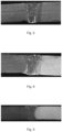
- the mechanical properties of the welding joint are shown in Table 4; the tensile curve of the welding joint is shown in Fig. 1 ; the fractured position is shown in Fig. 2 ; the metallographic phase of the joint is shown in Fig. 3 ; and the hardness of the joint is shown in Fig. 6 .
- the chemical compositions of the plates are shown in Tables 1 and 2.
- the steel plates were flat, and their surfaces were clean and free of oil and water stains.
- the to-be-welded edges of the high-strength and low-strength blanks were prepared by laser cutting. Before welding, the butt gap was preset at 0.4 mm. The welding wire developed by the invention was used.
- a laser power of 4.5 kW, a spot diameter of 2 mm, a defocus distance of -3 m, a welding speed of 80 mm/s, a welding wire diameter of 1.2 mm, and a wire feeding speed of 80 mm/s were employed.
- the composition of the welding wire is shown in Table 3.
- High-purity argon was used as a shielding gas.
- the gas flow rate was 15 L/min.
- the gas feeding direction was at an angle of 60 degrees relative to the welding direction.
- the blanks were heated at 930 °C for 4 minutes and cooled in a water-passing mold for 10 seconds.
- the mechanical properties of the welding joint are shown in Table 4; the tensile curve of the welding joint is shown in Fig. 1 ; the fractured position is shown in Fig. 2 ; and the metallographic phase of the joint is shown in Fig. 4 .
- the chemical compositions of the plates are shown in Tables 1 and 2.
- the steel plates were flat, and their surfaces were clean and free of oil and water stains.
- the to-be-welded edges of the high-strength and low-strength blanks were prepared by laser cutting. Before welding, the butt gap was preset at 0.25 mm. The welding wire developed by the invention was used.
- a laser power of 4 kW, a spot diameter of 2 mm, a defocus distance of -1 mm, a welding speed of 60 mm/s, a welding wire diameter of 1.2 mm, and a wire feeding speed of 60 mm/s were employed.
- the composition of the welding wire is shown in Table 3.
- High-purity argon was used as a shielding gas.
- the gas flow rate was 15 L/min.
- the gas feeding direction was at an angle of 120 degrees relative to the welding direction.
- the blanks were heated at 930 °C for 4 minutes and cooled in a water-passing mold for 10 seconds.
- the mechanical properties of the welding joint are shown in Table 4; the tensile curve of the welding joint is shown in Fig. 1 ; the fractured position is shown in Fig. 2 ; and the metallographic phase of the joint is shown in Fig. 5 .
- the chemical compositions of the plates are shown in Tables 1 and 2.
- the steel plates were flat, and their surfaces were clean and free of oil and water stains.
- the to-be-welded edges of the high-strength and low-strength blanks were prepared by laser cutting. Before welding, the butt gap was preset at 0.3 mm. The welding wire developed by the invention was used.
- a laser power of 4.5 kW, a spot diameter of 2 mm, a defocus distance of -2 mm, a welding speed of 80 mm/s, a welding wire diameter of 1.2 mm, and a wire feeding speed of 70 mm/s were employed.
- the composition of the welding wire is shown in Table 3.
- High-purity argon was used as a shielding gas.
- the gas flow rate was 15 L/min.
- the gas feeding direction was at an angle of 90 degrees relative to the welding direction.
- the chemical compositions of the plates are shown in Tables 1 and 2.
- the steel plates were flat, and their surfaces were clean and free of oil and water stains.
- the to-be-welded edges of the high-strength and low-strength blanks were prepared by laser cutting. Before welding, the butt gap was preset at 0.3 mm. The welding wire developed by the invention was used.
- a laser power of 4.5 kW, a spot diameter of 1.4 mm, a defocus distance of -1 mm, a welding speed of 75 mm/s, a welding wire diameter of 1.0 mm, and a wire feeding speed of 100 mm/s were employed.
- the composition of the welding wire is shown in Table 3.
- High-purity argon was used as a shielding gas.
- the gas flow rate was 15 L/min.
- the gas feeding direction was at an angle of 90 degrees relative to the welding direction.
- the chemical compositions of the plates are shown in Tables 1 and 2.
- the steel plates were flat, and their surfaces were clean and free of oil and water stains.
- the to-be-welded edges of the high-strength and low-strength blanks were prepared by laser cutting. Before welding, the butt gap was preset at 0.3 mm. The welding wire developed by the invention was used.
- a laser power of 5.5 kW, a spot diameter of 1.4 mm, a defocus distance of -2 mm, a welding speed of 120 mm/s, a welding wire diameter of 1.2 mm, and a wire feeding speed of 70 mm/s were employed.
- the composition of the welding wire is shown in Table 3.
- High-purity argon was used as a shielding gas.
- the gas flow rate was 15 L/min.
- the gas feeding direction was at an angle of 90 degrees relative to the welding direction.
- the chemical compositions of the plates are shown in Tables 1 and 2.
- the steel plates were flat, and their surfaces were clean and free of oil and water stains.
- the to-be-welded edges of the high-strength and low-strength blanks were prepared by laser cutting. Before welding, the butt gap was preset at 0.3 mm. The welding wire developed by the invention was used.
- a laser power of 4.5 kW, a spot diameter of 2 mm, a defocus distance of -2 mm, a welding speed of 100 mm/s, a welding wire diameter of 1.2 mm, and a wire feeding speed of 50 mm/s were employed.
- the composition of the welding wire is shown in Table 3.
- High-purity argon was used as a shielding gas.
- the gas flow rate was 15 L/min.
- the gas feeding direction was at an angle of 90 degrees relative to the welding direction.
- the chemical compositions of the plates are shown in Tables 1 and 2.
- the steel plates were flat, and their surfaces were clean and free of oil and water stains.
- the to-be-welded edges of the high-strength and low-strength blanks were prepared by laser cutting. Before welding, the butt gap was preset at 0.3 mm. The welding wire developed by the invention was used.
- a laser power of 4.5 kW, a spot diameter of 2.0 mm, a defocus distance of -1 mm, a welding speed of 80 mm/s, a welding wire diameter of 1.2 mm, and a wire feeding speed of 80 mm/s were employed.
- the composition of the welding wire is shown in Table 3.
- High-purity argon was used as a shielding gas.
- the gas flow rate was 15 L/min.
- the gas feeding direction was at an angle of 90 degrees relative to the welding direction.
- the chemical compositions of the plates are shown in Tables 1 and 2.
- the steel plates were flat, and their surfaces were clean and free of oil and water stains.
- the to-be-welded edges of the high-strength and low-strength blanks were prepared by laser cutting. Before welding, the butt gap was preset at 0.3 mm. The welding wire developed by the invention was used.
- a laser power of 5 kW, a spot diameter of 2 mm, a defocus distance of -1 mm, a welding speed of 120 mm/s, a welding wire diameter of 1.2 mm, and a wire feeding speed of 50 mm/s were employed.
- the composition of the welding wire is shown in Table 3.
- High-purity argon was used as a shielding gas.
- the gas flow rate was 15 L/min.
- the gas feeding direction was at an angle of 90 degrees relative to the welding direction.
- the chemical compositions of the plates are shown in Tables 1 and 2.
- the steel plates were flat, and their surfaces were clean and free of oil and water stains.
- the to-be-welded edges of the high-strength and low-strength blanks were prepared by laser cutting. Before welding, the butt gap was preset at 0.3 mm. The welding wire developed by the invention was used.
- a laser power of 4.5 kW, a spot diameter of 1.4 mm, a defocus distance of -1 mm, a welding speed of 80 mm/s, a welding wire diameter of 1.0 mm, and a wire feeding speed of 100 mm/s were employed.
- the composition of the welding wire is shown in Table 3.
- High-purity argon was used as a shielding gas.
- the gas flow rate was 15 L/min.
- the gas feeding direction was at an angle of 90 degrees relative to the welding direction.
- the chemical compositions of the plates are shown in Tables 1 and 2.
- the steel plates were flat, and their surfaces were clean and free of oil and water stains.
- the to-be-welded edges of the high-strength and low-strength blanks were prepared by laser cutting. Before welding, the butt gap was preset at 0.3 mm. The same welding wire as that used in Example 10 was used.
- a welding current of 120 A, a welding voltage of 22 V, a welding speed of 500 mm/min, a preset gap of 0.5 mm between the plates to be tailor welded, and a welding wire diameter of 1.0 mm were employed.
- the shielding gas was 80% argon + 20% carbon dioxide.
- the gas flow rate was 15 L/min.
- the gas feeding direction was at an angle of 90 degrees relative to the welding direction.
Landscapes
- Engineering & Computer Science (AREA)
- Physics & Mathematics (AREA)
- Mechanical Engineering (AREA)
- Optics & Photonics (AREA)
- Plasma & Fusion (AREA)
- Chemical & Material Sciences (AREA)
- Materials Engineering (AREA)
- Laser Beam Processing (AREA)
- Arc Welding In General (AREA)
- Coating With Molten Metal (AREA)
- Butt Welding And Welding Of Specific Article (AREA)
Applications Claiming Priority (3)
| Application Number | Priority Date | Filing Date | Title |
|---|---|---|---|
| CN201910249188.6A CN111215751B (zh) | 2019-03-29 | 2019-03-29 | 一种带铝或者铝合金镀层的钢制差强焊接部件及其制造方法 |
| PCT/CN2020/081743 WO2020200110A1 (zh) | 2019-03-29 | 2020-03-27 | 一种带铝或者铝合金镀层的钢制差强焊接部件及其制造方法 |
| EP20785301.1A EP3815837B1 (de) | 2019-03-29 | 2020-03-27 | Schweisskomponente aus stahl unterschiedlicher festigkeit mit aluminium- oder aluminiumlegierungsbeschichtung und verfahren zur herstellung desselben |
Related Parent Applications (1)
| Application Number | Title | Priority Date | Filing Date |
|---|---|---|---|
| EP20785301.1A Division EP3815837B1 (de) | 2019-03-29 | 2020-03-27 | Schweisskomponente aus stahl unterschiedlicher festigkeit mit aluminium- oder aluminiumlegierungsbeschichtung und verfahren zur herstellung desselben |
Publications (2)
| Publication Number | Publication Date |
|---|---|
| EP4474514A2 true EP4474514A2 (de) | 2024-12-11 |
| EP4474514A3 EP4474514A3 (de) | 2025-03-19 |
Family
ID=70830513
Family Applications (2)
| Application Number | Title | Priority Date | Filing Date |
|---|---|---|---|
| EP20785301.1A Active EP3815837B1 (de) | 2019-03-29 | 2020-03-27 | Schweisskomponente aus stahl unterschiedlicher festigkeit mit aluminium- oder aluminiumlegierungsbeschichtung und verfahren zur herstellung desselben |
| EP24208720.3A Pending EP4474514A3 (de) | 2019-03-29 | 2020-03-27 | Schweisskomponente aus stahl unterschiedlicher festigkeit mit aluminiumoder aluminiumlegierungsbeschichtung und verfahren zur herstellung desselben |
Family Applications Before (1)
| Application Number | Title | Priority Date | Filing Date |
|---|---|---|---|
| EP20785301.1A Active EP3815837B1 (de) | 2019-03-29 | 2020-03-27 | Schweisskomponente aus stahl unterschiedlicher festigkeit mit aluminium- oder aluminiumlegierungsbeschichtung und verfahren zur herstellung desselben |
Country Status (11)
| Country | Link |
|---|---|
| US (1) | US20220168845A1 (de) |
| EP (2) | EP3815837B1 (de) |
| JP (1) | JP7343603B2 (de) |
| KR (1) | KR102818575B1 (de) |
| CN (1) | CN111215751B (de) |
| ES (1) | ES2996872T3 (de) |
| FI (1) | FI3815837T3 (de) |
| HU (1) | HUE069437T2 (de) |
| PL (1) | PL3815837T3 (de) |
| SI (1) | SI3815837T1 (de) |
| WO (1) | WO2020200110A1 (de) |
Families Citing this family (18)
| Publication number | Priority date | Publication date | Assignee | Title |
|---|---|---|---|---|
| CN112404129B (zh) * | 2020-10-27 | 2023-05-02 | 苏州大学 | 一种热轧汽车用钢板的焊接方法 |
| CN112455024B (zh) * | 2021-02-03 | 2021-04-27 | 育材堂(苏州)材料科技有限公司 | 激光拼焊预镀层钢板及其热冲压成形构件 |
| CN114959441A (zh) * | 2021-02-26 | 2022-08-30 | 宝山钢铁股份有限公司 | 一种热冲压钢板、热冲压部件及其制造方法 |
| CN113118629A (zh) * | 2021-04-21 | 2021-07-16 | 攀钢集团攀枝花钢铁研究院有限公司 | 差强度激光拼焊板的制备方法 |
| CN113118630A (zh) * | 2021-04-21 | 2021-07-16 | 攀钢集团攀枝花钢铁研究院有限公司 | 差厚度激光拼焊板的制备方法 |
| EP4094879A1 (de) * | 2021-05-28 | 2022-11-30 | Volvo Car Corporation | Verfahren zum laserschweissen |
| CN113523573B (zh) * | 2021-06-21 | 2023-05-09 | 甘肃酒钢集团宏兴钢铁股份有限公司 | 一种高碳马氏体不锈钢热轧卷板焊接方法 |
| CN113500292A (zh) * | 2021-07-28 | 2021-10-15 | 攀钢集团研究院有限公司 | 一种含钒双相钢激光拼焊板的生产方法 |
| CN115722795B (zh) * | 2021-08-25 | 2024-09-10 | 宝山钢铁股份有限公司 | 一种钢制薄壁拼焊件的制造方法及使用该拼焊件制备的热冲压部件 |
| US20240367261A1 (en) * | 2021-09-15 | 2024-11-07 | Jfe Steel Corporation | Laser welding method for si-containing steel sheets |
| WO2023042636A1 (ja) * | 2021-09-15 | 2023-03-23 | Jfeスチール株式会社 | Si含有鋼板のレーザ溶接方法 |
| CN119658135A (zh) * | 2022-10-14 | 2025-03-21 | 中国科学院上海光学精密机械研究所 | 一种高强钢激光焊接填料、接头及方法 |
| KR102709440B1 (ko) * | 2022-12-27 | 2024-09-24 | 현대제철 주식회사 | 알루미늄계 도금 블랭크 |
| KR102709439B1 (ko) * | 2022-12-27 | 2024-09-24 | 현대제철 주식회사 | 알루미늄계 도금 블랭크 |
| DE102023121542A1 (de) | 2023-08-11 | 2025-02-13 | Thyssenkrupp Steel Europe Ag | Maßgeschneidertes Halbzeug und äußere Seitenwandverstärkung |
| CN116810153B (zh) * | 2023-08-23 | 2023-11-07 | 华安钢宝利高新汽车板加工(沈阳)有限公司 | 汽车门环焊渣自清洁式激光拼焊系统 |
| DE102024100229A1 (de) | 2024-01-04 | 2025-07-10 | Thyssenkrupp Steel Europe Ag | Maßgeschneidertes Halbzeug und Seitenwandverstärkung |
| CN118492629B (zh) * | 2024-07-18 | 2024-11-12 | 上海大学 | 镀铝硅钢板激光焊接方法、焊丝以及制备工艺 |
Citations (1)
| Publication number | Priority date | Publication date | Assignee | Title |
|---|---|---|---|---|
| CN101426612A (zh) | 2006-04-19 | 2009-05-06 | 安赛乐米塔尔法国公司 | 由滚轧的涂镀板制造具有良好机械特性的焊接部件的方法 |
Family Cites Families (42)
| Publication number | Priority date | Publication date | Assignee | Title |
|---|---|---|---|---|
| JP3205449B2 (ja) * | 1993-12-17 | 2001-09-04 | 新日本製鐵株式会社 | レーザー溶接用フィラワイヤ |
| FR2830477B1 (fr) * | 2001-10-09 | 2004-02-06 | Usinor | Procede et dispositif de soudage par recouvrement a l'aide d'un faisceau a haute densite d'energie de deux toles revetues |
| FR2865152B1 (fr) * | 2004-01-21 | 2007-02-02 | Air Liquide | Procede de soudage hybride arc-laser des aciers ferritiques |
| JP4498039B2 (ja) * | 2004-07-07 | 2010-07-07 | 株式会社神戸製鋼所 | レーザ・アーク複合溶接用ソリッドワイヤ及びレーザ・アーク複合溶接方法 |
| JP4794413B2 (ja) | 2006-10-25 | 2011-10-19 | 株式会社神戸製鋼所 | ガスシールドアーク溶接用ソリッドワイヤ |
| JP5205115B2 (ja) * | 2008-04-16 | 2013-06-05 | 株式会社神戸製鋼所 | 純Arシールドガス溶接用MIGフラックス入りワイヤ及びMIGアーク溶接方法 |
| KR100981856B1 (ko) * | 2010-02-26 | 2010-09-13 | 현대하이스코 주식회사 | 도금성이 우수한 고강도 강판 제조 방법 |
| JP5827454B2 (ja) * | 2010-03-08 | 2015-12-02 | 株式会社神戸製鋼所 | レーザー・アーク複合溶接方法及び該溶接方法による溶接部材の製造方法 |
| FR2962673B1 (fr) * | 2010-07-13 | 2013-03-08 | Air Liquide | Procede de soudage hybride arc/laser de pieces en acier aluminise avec fil a elements gamagenes |
| JP5270043B2 (ja) * | 2011-02-01 | 2013-08-21 | 三菱重工業株式会社 | Ni基高Cr合金溶接ワイヤ、被覆アーク溶接棒及び被覆アーク溶着金属 |
| WO2012153008A1 (fr) | 2011-05-12 | 2012-11-15 | Arcelormittal Investigación Y Desarrollo Sl | Procede de fabrication d'acier martensitique a tres haute resistance et tole ou piece ainsi obtenue |
| WO2013014481A1 (fr) * | 2011-07-26 | 2013-01-31 | Arcelormittal Investigación Y Desarrollo Sl | Pièce d'acier soudée préalablement mise en forme à chaud à très haute résistance mécanique et procédé de fabrication |
| JP5316670B1 (ja) * | 2012-04-17 | 2013-10-16 | 新日鐵住金株式会社 | ホットスタンプ用のテーラードブランクとその製造方法 |
| JP5316664B2 (ja) | 2012-03-28 | 2013-10-16 | 新日鐵住金株式会社 | ホットスタンプ用のテーラードブランク |
| WO2013147035A1 (ja) * | 2012-03-28 | 2013-10-03 | 新日鐵住金株式会社 | ホットスタンプ用テーラードブランクおよびホットスタンプ部材ならびにそれらの製造方法 |
| CN103831531B (zh) * | 2012-11-23 | 2016-09-14 | 通用汽车环球科技运作有限责任公司 | 焊接接头 |
| MX381438B (es) * | 2012-11-30 | 2025-03-04 | Twb Company Llc | Metodo para formar una muesca de soldadura en una pieza de metal en hoja. |
| KR101448473B1 (ko) * | 2012-12-03 | 2014-10-10 | 현대하이스코 주식회사 | 테일러 웰디드 블랭크, 그 제조방법 및 이를 이용한 핫스탬핑 부품 |
| JP6056450B2 (ja) | 2012-12-19 | 2017-01-11 | 新日鐵住金株式会社 | ホットスタンプ用溶融Alめっき鋼板およびその製造方法、ならびにホットスタンプ製品 |
| EP2944417A4 (de) * | 2013-01-11 | 2016-08-24 | Kobe Steel Ltd | Geschweisstes metall mit ausgezeichneter beständigkeit gegenüber wasserstoffversprödung und volldraht zum unterpulverschweissen |
| US20160008906A1 (en) * | 2013-02-15 | 2016-01-14 | Nippon Steel & Sumitomo Metal Corporation | Solid wire for gas shielded arc welding, weld metal by gas shielded arc welding, welded joint, weldment, welding method, and production method of welded joint |
| DE102013215346B4 (de) * | 2013-08-05 | 2017-12-07 | Trumpf Laser- Und Systemtechnik Gmbh | Verfahren zum Laserentschichten von beschichteten Blechen und zugehörige Laserentschichtungsanlage |
| KR20150025952A (ko) * | 2013-08-30 | 2015-03-11 | 현대제철 주식회사 | 고강도 열연도금강판 및 그 제조 방법 |
| US10112268B2 (en) * | 2013-10-09 | 2018-10-30 | Hobart Brothers Company | Systems and methods for corrosion-resistant welding electrodes |
| EP2883646B1 (de) * | 2013-12-12 | 2016-11-02 | Autotech Engineering, A.I.E. | Verfahren zum Verbinden von zwei Rohlingen sowie Rohlinge und erhaltenes Produkte |
| KR101562987B1 (ko) * | 2013-12-12 | 2015-10-23 | 주식회사 포스코 | 필러 와이어, 이를 사용하는 열간성형강의 용접방법 및 강판 제조방법 |
| JP6576348B2 (ja) * | 2013-12-24 | 2019-09-18 | ポスコPosco | 衝撃靱性に優れた超高強度ガスメタルアーク溶接継手 |
| DE102014001979A1 (de) * | 2014-02-17 | 2015-08-20 | Wisco Tailored Blanks Gmbh | Verfahren zum Laserschweißen eines oder mehrerer Werkstücke aus härtbarem Stahl im Stumpfstoß |
| US10052720B2 (en) * | 2014-09-17 | 2018-08-21 | Magna International Inc. | Method of laser welding coated steel sheets with addition of alloying elements |
| DE102014114365A1 (de) * | 2014-10-02 | 2016-04-07 | Thyssenkrupp Steel Europe Ag | Mehrschichtiges Stahlflachprodukt und daraus hergestelltes Bauteil |
| US10300565B2 (en) * | 2014-10-17 | 2019-05-28 | Hobart Brothers Company | Systems and methods for welding mill scaled workpieces |
| KR101714121B1 (ko) * | 2014-11-21 | 2017-03-09 | 현대자동차주식회사 | 테일러 웰디드 블랭크 제조방법 |
| DE102015115915A1 (de) * | 2015-09-21 | 2017-03-23 | Wisco Tailored Blanks Gmbh | Laserschweißverfahren zur Herstellung eines Blechhalbzeugs aus härtbarem Stahl mit einer Beschichtung auf Aluminium- oder Aluminium-Silizium-Basis |
| US10722986B2 (en) * | 2015-12-11 | 2020-07-28 | Hobart Brothers Llc | Systems and methods for low-manganese welding wire |
| CN106334875A (zh) * | 2016-10-27 | 2017-01-18 | 宝山钢铁股份有限公司 | 一种带铝或者铝合金镀层的钢制焊接部件及其制造方法 |
| CN106736013A (zh) * | 2016-11-28 | 2017-05-31 | 安徽飞弧焊业股份有限公司 | 一种低合金高强钢焊接用涂层焊丝及制备方法 |
| CN108213711A (zh) * | 2018-01-12 | 2018-06-29 | 上海交通大学 | 一种用激光填丝焊工艺制造铝硅镀层热成形钢拼焊板的方法 |
| WO2019166852A1 (en) * | 2018-02-27 | 2019-09-06 | Arcelormittal | Method for producing a press-hardened laser welded steel part and press-hardened laser welded steel part |
| CN112368105B (zh) * | 2018-06-27 | 2022-11-18 | 麦格纳国际公司 | 利用填充丝对涂覆的钢坯件进行激光焊接 |
| CN108838541B (zh) * | 2018-09-14 | 2020-07-24 | 苏州大学 | 一种汽车用冷轧钢板的激光焊接方法及其焊接接头 |
| CN111230301B (zh) * | 2019-03-29 | 2022-08-12 | 宝山钢铁股份有限公司 | 带铝或铝合金镀层的钢制薄壁焊接等强部件的制造方法 |
| CN115722795B (zh) * | 2021-08-25 | 2024-09-10 | 宝山钢铁股份有限公司 | 一种钢制薄壁拼焊件的制造方法及使用该拼焊件制备的热冲压部件 |
-
2019
- 2019-03-29 CN CN201910249188.6A patent/CN111215751B/zh active Active
-
2020
- 2020-03-27 JP JP2021551592A patent/JP7343603B2/ja active Active
- 2020-03-27 EP EP20785301.1A patent/EP3815837B1/de active Active
- 2020-03-27 FI FIEP20785301.1T patent/FI3815837T3/fi active
- 2020-03-27 KR KR1020217025700A patent/KR102818575B1/ko active Active
- 2020-03-27 PL PL20785301.1T patent/PL3815837T3/pl unknown
- 2020-03-27 WO PCT/CN2020/081743 patent/WO2020200110A1/zh not_active Ceased
- 2020-03-27 HU HUE20785301A patent/HUE069437T2/hu unknown
- 2020-03-27 EP EP24208720.3A patent/EP4474514A3/de active Pending
- 2020-03-27 ES ES20785301T patent/ES2996872T3/es active Active
- 2020-03-27 SI SI202030550T patent/SI3815837T1/sl unknown
- 2020-03-27 US US17/598,007 patent/US20220168845A1/en active Pending
Patent Citations (1)
| Publication number | Priority date | Publication date | Assignee | Title |
|---|---|---|---|---|
| CN101426612A (zh) | 2006-04-19 | 2009-05-06 | 安赛乐米塔尔法国公司 | 由滚轧的涂镀板制造具有良好机械特性的焊接部件的方法 |
Also Published As
| Publication number | Publication date |
|---|---|
| KR102818575B1 (ko) | 2025-06-10 |
| HUE069437T2 (hu) | 2025-03-28 |
| US20220168845A1 (en) | 2022-06-02 |
| ES2996872T3 (en) | 2025-02-13 |
| JP2022522761A (ja) | 2022-04-20 |
| WO2020200110A1 (zh) | 2020-10-08 |
| JP7343603B2 (ja) | 2023-09-12 |
| CN111215751B (zh) | 2022-06-28 |
| EP4474514A3 (de) | 2025-03-19 |
| CN111215751A (zh) | 2020-06-02 |
| KR20210145725A (ko) | 2021-12-02 |
| EP3815837B1 (de) | 2024-10-30 |
| FI3815837T3 (fi) | 2024-12-02 |
| EP3815837A4 (de) | 2022-08-03 |
| SI3815837T1 (sl) | 2025-03-31 |
| PL3815837T3 (pl) | 2025-02-10 |
| EP3815837A1 (de) | 2021-05-05 |
Similar Documents
| Publication | Publication Date | Title |
|---|---|---|
| EP3815837B1 (de) | Schweisskomponente aus stahl unterschiedlicher festigkeit mit aluminium- oder aluminiumlegierungsbeschichtung und verfahren zur herstellung desselben | |
| EP3812079B1 (de) | Verfahren zur herstellung einer gleichstarken dünnwandigen schweisskomponente mit aluminium- oder aluminiumlegierungsplattierung | |
| KR101764519B1 (ko) | 가스 실드 아크 용접용 솔리드 와이어, 가스 실드 아크 용접 금속, 용접 조인트, 용접 부재, 용접 방법 및 용접 조인트의 제조 방법 | |
| EP2143816B1 (de) | Schmelztauchbeschichtetes hochfestes Stahlblech zur Verwendung in der Pressbearbeitung mit hervorragender Tieftemperaturzähigkeit und Herstellungsverfahren dafür | |
| CN103415641B (zh) | 热浸镀Zn-Al-Mg系的钢板及制造方法 | |
| EP2816139A1 (de) | Plattiertes stahlblech zum heisspressen sowie verfahren zum heisspressen des plattierten stahlblechs | |
| CN112743228B (zh) | 激光焊接接头及汽车用骨架零件 | |
| KR102065287B1 (ko) | 도금성 및 용접성이 우수한 오스테나이트계 용융 알루미늄 도금강판 및 그 제조방법 | |
| EP4393628A1 (de) | Widerstandspunktgeschweisstes element und widerstandspunktschweissverfahren dafür | |
| JP7277834B2 (ja) | アルミニウムめっき鋼板の溶接用ソリッドワイヤ、及び溶接継手の製造方法 | |
| CN118357583B (zh) | 一种焊料、激光焊接接头及其制造方法 | |
| CN118357579B (zh) | 一种焊料、激光焊接接头及其制造方法 | |
| JP6373549B2 (ja) | ガスシールドアーク溶接方法 | |
| KR20160054111A (ko) | 점용접성 및 도금성이 우수한 고망간강 합금아연도금강판 및 이의 제조방법 | |
| KR101630960B1 (ko) | 가공성 및 점용접성이 우수한 합금화 용융아연도금강판 및 그 제조방법 | |
| KR20130138038A (ko) | 용접성 및 가공성이 우수한 초고강도 강판 및 그 제조방법 | |
| EP4306254A1 (de) | Lichtbogenschweissverbindung und lichtbogenschweissverfahren | |
| EP2899290A1 (de) | Gehärteter stahlrohrelement, achskörpr eines kraftfahrzeugs mit dem gehärteten stahlrohrelement und verfahren zur herstellung eines gehärteten stahlrohrelements | |
| EP4527542A1 (de) | Gasschild-lichtbogenschweissmetall |
Legal Events
| Date | Code | Title | Description |
|---|---|---|---|
| PUAI | Public reference made under article 153(3) epc to a published international application that has entered the european phase |
Free format text: ORIGINAL CODE: 0009012 |
|
| STAA | Information on the status of an ep patent application or granted ep patent |
Free format text: STATUS: THE APPLICATION HAS BEEN PUBLISHED |
|
| AC | Divisional application: reference to earlier application |
Ref document number: 3815837 Country of ref document: EP Kind code of ref document: P |
|
| AK | Designated contracting states |
Kind code of ref document: A2 Designated state(s): AL AT BE BG CH CY CZ DE DK EE ES FI FR GB GR HR HU IE IS IT LI LT LU LV MC MK MT NL NO PL PT RO RS SE SI SK SM TR |
|
| REG | Reference to a national code |
Ref country code: DE Ref legal event code: R079 Free format text: PREVIOUS MAIN CLASS: C22C0038020000 Ipc: B23K0026260000 |
|
| PUAL | Search report despatched |
Free format text: ORIGINAL CODE: 0009013 |
|
| AK | Designated contracting states |
Kind code of ref document: A3 Designated state(s): AL AT BE BG CH CY CZ DE DK EE ES FI FR GB GR HR HU IE IS IT LI LT LU LV MC MK MT NL NO PL PT RO RS SE SI SK SM TR |
|
| RIC1 | Information provided on ipc code assigned before grant |
Ipc: B23K 35/30 20060101ALI20250207BHEP Ipc: B23K 35/02 20060101ALI20250207BHEP Ipc: C22C 38/02 20060101ALI20250207BHEP Ipc: C22C 38/04 20060101ALI20250207BHEP Ipc: C22C 38/06 20060101ALI20250207BHEP Ipc: C22C 38/28 20060101ALI20250207BHEP Ipc: C22C 38/32 20060101ALI20250207BHEP Ipc: C22C 38/38 20060101ALI20250207BHEP Ipc: B23K 26/12 20140101ALI20250207BHEP Ipc: B23K 26/322 20140101ALI20250207BHEP Ipc: B23K 26/26 20140101AFI20250207BHEP |
|
| STAA | Information on the status of an ep patent application or granted ep patent |
Free format text: STATUS: REQUEST FOR EXAMINATION WAS MADE |
|
| 17P | Request for examination filed |
Effective date: 20250918 |
|
| STAA | Information on the status of an ep patent application or granted ep patent |
Free format text: STATUS: EXAMINATION IS IN PROGRESS |
|
| 17Q | First examination report despatched |
Effective date: 20260211 |