EP4474228A1 - Fahrzeugsitz mit gurtsystem - Google Patents
Fahrzeugsitz mit gurtsystem Download PDFInfo
- Publication number
- EP4474228A1 EP4474228A1 EP24174912.6A EP24174912A EP4474228A1 EP 4474228 A1 EP4474228 A1 EP 4474228A1 EP 24174912 A EP24174912 A EP 24174912A EP 4474228 A1 EP4474228 A1 EP 4474228A1
- Authority
- EP
- European Patent Office
- Prior art keywords
- vehicle seat
- belt
- deflection
- spacing element
- spacing
- Prior art date
- Legal status (The legal status is an assumption and is not a legal conclusion. Google has not performed a legal analysis and makes no representation as to the accuracy of the status listed.)
- Granted
Links
Images


Classifications
-
- B—PERFORMING OPERATIONS; TRANSPORTING
- B60—VEHICLES IN GENERAL
- B60N—SEATS SPECIALLY ADAPTED FOR VEHICLES; VEHICLE PASSENGER ACCOMMODATION NOT OTHERWISE PROVIDED FOR
- B60N2/00—Seats specially adapted for vehicles; Arrangement or mounting of seats in vehicles
- B60N2/68—Seat frames
- B60N2/688—Particular seat belt attachment and guiding
-
- B—PERFORMING OPERATIONS; TRANSPORTING
- B60—VEHICLES IN GENERAL
- B60R—VEHICLES, VEHICLE FITTINGS, OR VEHICLE PARTS, NOT OTHERWISE PROVIDED FOR
- B60R22/00—Safety belts or body harnesses in vehicles
- B60R22/18—Anchoring devices
-
- B—PERFORMING OPERATIONS; TRANSPORTING
- B60—VEHICLES IN GENERAL
- B60R—VEHICLES, VEHICLE FITTINGS, OR VEHICLE PARTS, NOT OTHERWISE PROVIDED FOR
- B60R22/00—Safety belts or body harnesses in vehicles
- B60R22/34—Belt retractors, e.g. reels
- B60R22/341—Belt retractors, e.g. reels comprising energy-absorbing means
-
- B—PERFORMING OPERATIONS; TRANSPORTING
- B60—VEHICLES IN GENERAL
- B60N—SEATS SPECIALLY ADAPTED FOR VEHICLES; VEHICLE PASSENGER ACCOMMODATION NOT OTHERWISE PROVIDED FOR
- B60N2/00—Seats specially adapted for vehicles; Arrangement or mounting of seats in vehicles
- B60N2/02—Seats specially adapted for vehicles; Arrangement or mounting of seats in vehicles the seat or part thereof being movable, e.g. adjustable
- B60N2/0284—Adjustable seat-cushion length
-
- B—PERFORMING OPERATIONS; TRANSPORTING
- B60—VEHICLES IN GENERAL
- B60N—SEATS SPECIALLY ADAPTED FOR VEHICLES; VEHICLE PASSENGER ACCOMMODATION NOT OTHERWISE PROVIDED FOR
- B60N2/00—Seats specially adapted for vehicles; Arrangement or mounting of seats in vehicles
- B60N2/02—Seats specially adapted for vehicles; Arrangement or mounting of seats in vehicles the seat or part thereof being movable, e.g. adjustable
- B60N2/04—Seats specially adapted for vehicles; Arrangement or mounting of seats in vehicles the seat or part thereof being movable, e.g. adjustable the whole seat being movable
- B60N2/16—Seats specially adapted for vehicles; Arrangement or mounting of seats in vehicles the seat or part thereof being movable, e.g. adjustable the whole seat being movable height-adjustable
- B60N2/1605—Seats specially adapted for vehicles; Arrangement or mounting of seats in vehicles the seat or part thereof being movable, e.g. adjustable the whole seat being movable height-adjustable characterised by the cinematic
- B60N2/161—Rods
- B60N2/1615—Parallelogram-like structure
-
- B—PERFORMING OPERATIONS; TRANSPORTING
- B60—VEHICLES IN GENERAL
- B60N—SEATS SPECIALLY ADAPTED FOR VEHICLES; VEHICLE PASSENGER ACCOMMODATION NOT OTHERWISE PROVIDED FOR
- B60N2/00—Seats specially adapted for vehicles; Arrangement or mounting of seats in vehicles
- B60N2/24—Seats specially adapted for vehicles; Arrangement or mounting of seats in vehicles for particular purposes or particular vehicles
- B60N2/30—Non-dismountable or dismountable seats storable in a non-use position, e.g. foldable spare seats
- B60N2/3002—Non-dismountable or dismountable seats storable in a non-use position, e.g. foldable spare seats back-rest movements
- B60N2/3004—Non-dismountable or dismountable seats storable in a non-use position, e.g. foldable spare seats back-rest movements by rotation only
- B60N2/3009—Non-dismountable or dismountable seats storable in a non-use position, e.g. foldable spare seats back-rest movements by rotation only about transversal axis
- B60N2/3011—Non-dismountable or dismountable seats storable in a non-use position, e.g. foldable spare seats back-rest movements by rotation only about transversal axis the back-rest being hinged on the cushion, e.g. "portefeuille movement"
-
- B—PERFORMING OPERATIONS; TRANSPORTING
- B60—VEHICLES IN GENERAL
- B60N—SEATS SPECIALLY ADAPTED FOR VEHICLES; VEHICLE PASSENGER ACCOMMODATION NOT OTHERWISE PROVIDED FOR
- B60N2/00—Seats specially adapted for vehicles; Arrangement or mounting of seats in vehicles
- B60N2/24—Seats specially adapted for vehicles; Arrangement or mounting of seats in vehicles for particular purposes or particular vehicles
- B60N2/30—Non-dismountable or dismountable seats storable in a non-use position, e.g. foldable spare seats
- B60N2/3088—Non-dismountable or dismountable seats storable in a non-use position, e.g. foldable spare seats characterised by the mechanical link
- B60N2/309—Non-dismountable or dismountable seats storable in a non-use position, e.g. foldable spare seats characterised by the mechanical link rods
-
- B—PERFORMING OPERATIONS; TRANSPORTING
- B60—VEHICLES IN GENERAL
- B60N—SEATS SPECIALLY ADAPTED FOR VEHICLES; VEHICLE PASSENGER ACCOMMODATION NOT OTHERWISE PROVIDED FOR
- B60N2/00—Seats specially adapted for vehicles; Arrangement or mounting of seats in vehicles
- B60N2/58—Seat coverings
- B60N2/5816—Seat coverings attachments thereof
- B60N2/5825—Seat coverings attachments thereof by hooks, staples, clips, snap fasteners or the like
-
- B—PERFORMING OPERATIONS; TRANSPORTING
- B60—VEHICLES IN GENERAL
- B60N—SEATS SPECIALLY ADAPTED FOR VEHICLES; VEHICLE PASSENGER ACCOMMODATION NOT OTHERWISE PROVIDED FOR
- B60N2/00—Seats specially adapted for vehicles; Arrangement or mounting of seats in vehicles
- B60N2/64—Back-rests or cushions
-
- B—PERFORMING OPERATIONS; TRANSPORTING
- B60—VEHICLES IN GENERAL
- B60N—SEATS SPECIALLY ADAPTED FOR VEHICLES; VEHICLE PASSENGER ACCOMMODATION NOT OTHERWISE PROVIDED FOR
- B60N2/00—Seats specially adapted for vehicles; Arrangement or mounting of seats in vehicles
- B60N2/68—Seat frames
-
- B—PERFORMING OPERATIONS; TRANSPORTING
- B60—VEHICLES IN GENERAL
- B60N—SEATS SPECIALLY ADAPTED FOR VEHICLES; VEHICLE PASSENGER ACCOMMODATION NOT OTHERWISE PROVIDED FOR
- B60N2/00—Seats specially adapted for vehicles; Arrangement or mounting of seats in vehicles
- B60N2/90—Details or parts not otherwise provided for
-
- B—PERFORMING OPERATIONS; TRANSPORTING
- B60—VEHICLES IN GENERAL
- B60R—VEHICLES, VEHICLE FITTINGS, OR VEHICLE PARTS, NOT OTHERWISE PROVIDED FOR
- B60R22/00—Safety belts or body harnesses in vehicles
- B60R22/18—Anchoring devices
- B60R22/20—Anchoring devices adjustable in position, e.g. in height
-
- B—PERFORMING OPERATIONS; TRANSPORTING
- B60—VEHICLES IN GENERAL
- B60R—VEHICLES, VEHICLE FITTINGS, OR VEHICLE PARTS, NOT OTHERWISE PROVIDED FOR
- B60R22/00—Safety belts or body harnesses in vehicles
- B60R22/18—Anchoring devices
- B60R22/26—Anchoring devices secured to the seat
-
- B—PERFORMING OPERATIONS; TRANSPORTING
- B60—VEHICLES IN GENERAL
- B60R—VEHICLES, VEHICLE FITTINGS, OR VEHICLE PARTS, NOT OTHERWISE PROVIDED FOR
- B60R22/00—Safety belts or body harnesses in vehicles
- B60R22/18—Anchoring devices
- B60R2022/1818—Belt guides
Definitions
- the present invention relates to a vehicle seat with a belt system, wherein the belt system has a belt element and a winding and unwinding mechanism which is provided and designed to wind and unwind the belt element, and wherein the belt system has a deflection unit with a deflection element, wherein the deflection element is provided and designed to deflect the belt element in the direction of a person.
- Such systems are well known from the state of the art, but have the basic disadvantage that they are relatively close to the vehicle seat or connected to the vehicle seat, so that a deflection or ergonomic belt guide for both tall and short drivers is not provided. Furthermore, it is known from the state of the art that the belt deflections or belt guides are relatively rigid, so that small movements of the person sitting on the vehicle seat cannot be followed.
- the core idea of the present invention is to provide a vehicle seat with a belt system, wherein the belt system has a belt element and a winding and unwinding mechanism which is provided and designed to roll up and unwind the belt element, and wherein the belt system has a deflection unit with a deflection element, wherein the deflection element is designed to deflect the belt element in the direction of a person.
- the deflection unit has an elastically deformable spacing element which is arranged on the vehicle seat and wherein the deflection element is arranged on the spacing element such that the deflection element is spaced from the vehicle seat.
- the fact that the deflection element is spaced apart from the vehicle seat means that the deflection element is at a certain distance from the vehicle seat.
- the deflection element is therefore connected to the vehicle seat, in particular indirectly, by means of the spacing element.
- belt element can also be understood as a belt strap.
- the winding and unwinding mechanism can also be understood as a belt retractor or belt rolling element.
- the wording that the belt element can be deflected in the direction of a person means in particular that the belt element can be guided and deflected by means of the deflection unit and in particular by means of the deflection element in such a way that the belt element can be deflected or guided by the winding and unwinding mechanism in the direction of the person.
- the person is a person who has taken a seat on the vehicle seat and is sitting on it.
- the spacer element acts as an intermediate element between the deflection element and the vehicle seat.
- the spacing element is designed to be elastically deformable, it can lead, in particular when forces, more preferably tensile forces, occur that the elastically deformable element can be elastically deformed. This means that the spacing element is arranged in its zero position in a state in which no forces act on the spacing element. If forces, in particular If tensile forces act on the elastically deformable spacing element, the spacing element can be elastically deformed by the forces or the forces acting on the spacing element, i.e. the spacing element is bent or curved into a deformed state. If the spacing element is in a deformed state and no further forces act on the spacing element, the spacing element moves from the deformed state back to its zero position.
- the forces acting on the spacing element particularly refer to the forces that can be transferred to the spacing element by means of or due to the forces acting on the belt element.
- forces can act on the belt element when the person sitting on the vehicle seat moves, during acceleration maneuvers, in accidents, and the like. Because the person wants to move relative to the vehicle seat in these cases, the person's movement is transferred to the belt element and then accordingly also to the spacing element.
- the elastically deformable spacing element is designed such that when the spacing element is deformed up to a predetermined limit angle, the Deformation of the spacing element is elastic and from the limit angle the deformation of the spacing element is plastic.
- a load on the spacer element changes from a bending load to a tensile load, thereby changing from an elastic deformation to a plastic deformation.
- the spacing element is or can be plastically deformed from a certain limit angle means that when particularly high or critical forces occur, the spacing element is plastically deformed, which means that forces can be absorbed in order to be able to absorb the loads of the person sitting on the vehicle seat. For smaller forces, it is intended that the spacing element can be elastically deformed up to the limit angle.
- the plastic deformation or deformation therefore has a safety aspect, particularly in the event of accidents, crashes or the like.
- the predetermined limit angle is 45°.
- the vehicle seat according to the invention can meet the requirements or demands of SAE J2292 and also pass the tensile test defined therein.
- the spacing element can be made particularly simple if the elastically deformable spacing element is designed in layers.
- the spacing element therefore particularly preferably has a layered structure, and the layered structure preferably consists of at least two layers. It can preferably be provided that the layers of the layered structure are designed in the same way. In the case of several layers, ie more than two layers, it can be provided that individual layers are designed identically to one another and further individual or further layers are designed differently. This can make it possible to design the spacing element in accordance with the existing requirements.
- the spacing element has a securing element which connects the various layers of the spacing element to one another and is preferably provided and designed to fail at an angle greater than the predetermined limit angle and therefore to enable the plastic deformation of the spacing element.
- the elastically deformable spacing element can be designed such that each layer of the layer structure is a leaf spring element.
- the layers can be designed differently, as already explained, so that the leaf spring elements can also be different from one another.
- the spacing element is elongated.
- the spacing element therefore preferably has an extension direction in which the elongated extension of the spacing element extends.
- Elongated also means that, in comparison to the extension in the extension direction, the height extension and the width extension are smaller than the extension in the extension direction.
- the spacer element has a first end and a second end.
- the first end is particularly preferably connected to the vehicle seat.
- the deflection element is arranged at the second end of the spacer element. It is preferably provided that the spacer element is firmly connected to the vehicle seat.
- the elastically deformable spacing element is displaced and/or arranged to be rotatable relative to the vehicle seat.
- the elastically deformable spacer element can be displaced relative to the vehicle seat.
- the elastically deformable spacer element is arranged so as to be rotatable relative to the vehicle seat. This can mean that by rotating the spacer element, the spacer element can be aligned accordingly.
- a displacement or a rotation of the spacer element relative to the vehicle seat represents a detachable connection, wherein the connection between the spacer element and the vehicle seat can be released and the spacer element can also be firmly connected to the vehicle seat again, in particular after a displacement and/or rotation of the spacer element.
- the elastically deformable spacer element can be provided particularly advantageously if the spacer element consists of one or more metals and/or metal alloys. It can be particularly preferably provided that the spacer element consists of or is made of a corrosion-resistant spring steel, in particular a non-rusting spring steel. By forming the spacer element from metals or metal alloys, a good balance between deformation and stability or rigidity can be provided.
- the material of corrosion-resistant spring steel is particularly preferred because it can provide the exact requirements for the spacing element.
- Stainless steel is also readily available and can still be purchased inexpensively.
- the deflection element is rotatably connected to the elastically deformable spacing element.
- the deflection element is rotatably connected to the spacing element, whereby the belt element, which extends through the deflection element or can be deflected by means of the deflection element, can easily follow a deflection of the belt element due to lateral stresses, i.e. due to the application of force perpendicular to a tensile force.
- the vehicle seat has a backrest. It is also preferably provided that the elastically deformable spacer element is connected to the backrest. This connection between the spacer element and the backrest is preferably such that the spacer element is arranged on a rear part of the backrest, on a side part of the backrest, and/or on an upper part of the backrest.
- the spacer element and, accordingly, the deflection element can be positioned accordingly so that the belt element can be positioned as well as possible with respect to the person sitting on the vehicle seat.
- the spacer element should be arranged in such a way that it does not interfere with the person while driving or using the vehicle seat. It is particularly preferred that the spacer element is arranged on the rear part of the backrest. This is particularly advantageous if the winding and unwinding mechanism is also arranged on the rear part of the backrest or is arranged behind the backrest. Fastening to a side part of the backrest depends on the space available to the left or right in the vehicle or with respect to the vehicle seat.
- the deflection element can be arranged at the same height as the headrest.
- the rolling up and down mechanism is arranged behind the backrest. Further preferably, it can be provided that the rolling up and down mechanism is arranged on a seat part of the vehicle seat and/or on a vehicle seat base.
- the seat part can accordingly be understood as the element of the vehicle seat on which the person can sit.
- the vehicle seat base can be understood in such a way that it represents a support part on which the vehicle seat itself is arranged.
- This arrangement of the rolling up and down mechanism means that when the vehicle seat is moved during longitudinal adjustment, width adjustment and/or height adjustment, the rolling up and down mechanism is moved with the vehicle seat or with the corresponding element. This also applies to rotation of the vehicle seat. This means that the rolling up and down mechanism can move equally with the vehicle seat or the lower part of the vehicle seat, so that this mechanism can be positioned accordingly.
- a guide element is arranged between the winding and unwinding mechanism and the deflection element for guiding the belt element.
- the guide element is provided and designed to guide the correspondingly provided belt element, i.e. in this case to guide it to the deflection element.
- the guide element is arranged between the vehicle seat and the elastically deformable spacing element. This makes it possible to efficiently utilize the space between the vehicle seat and the spacing element or between the backrest and the spacing element.
- the guide element is arranged on a side of the elastically deformable spacing element facing away from the vehicle seat.
- the corresponding guide element can be designed particularly advantageously in order to be able to ensure particularly good guidance of the belt element.
- the belt element is arranged between the vehicle seat and the elastically deformable spacing element, whereby a guide element can be dispensed with. If The guide element and the arrangement of the belt element between the spacing element and the vehicle seat already inherently provide guidance for the belt element.
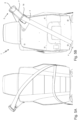
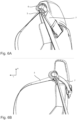
- FIG. 1A a vehicle seat 1 according to the known prior art is shown, wherein the vehicle seat 1 has a backrest RL on which a deflection unit 5 with a deflection element 6 is shown.
- a belt system 2 with a belt element 3 and the winding and unwinding mechanism 4 have been omitted at this point for clarity.
- the deflection element 6 is arranged relatively close to the backrest RL, so that an ergonomic or comfortable guidance and deflection of a belt element 3 cannot be provided.
- FIG. 1B a vehicle seat 1 according to a preferred embodiment of the invention is shown, wherein the deflection element 6 of the deflection unit 5 is arranged on the backrest RL on the vehicle seat 1.
- the deflection element 6 is connected to the backrest RL by means of a spacing element 7.
- the spacing element 7 makes it possible to arrange the deflection element 6, as shown, relatively far away from the backrest RL.
- FIG. 1C A comparison between the vehicle seat 1 according to the prior art and the vehicle seat 1 according to the present invention is shown in the Figure 1C shown, whereby it can be clearly seen how the arrangement of the respective deflection element 6 differs from the backrest RL or the vehicle seat 1.
- the deflection element 6 further out enables better or more optimal ergonomics of the belt system 2 or guidance of the belt element 3.
- the deflection element 6 can be arranged more than 100 mm in a width direction B and more than 50 mm in a height direction H further outwards with respect to the vehicle seat 1 compared to the prior art.
- the deflection element 6 can be arranged up to 130 mm in the width direction B and up to 80 mm in the height direction H further outwards compared to the prior art.
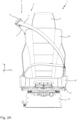
- FIG. 2A a vehicle seat 1 according to a preferred embodiment is shown from the front, in which Figure 2B in a side view and in the Figure 2C in a perspective view from behind.
- the vehicle seat 1 according to a preferred embodiment comprises a backrest RL, a seat part ST and a vehicle seat lower part UT, wherein the vehicle seat lower part UT is arranged below the seat part ST, and wherein the seat part ST is connected to the vehicle seat lower part UT.
- the vehicle seat lower part UT further preferably comprises a spring and/or damping unit 18, which is only identified as an example in this example and spring units and damping units per se have been dispensed with.
- the vehicle seat 1 can comprise a headrest K.
- the belt system 2 is also shown with a belt element 3, whereby the belt system 2 can represent a 3-point belt known from the prior art.
- the deflection element 6 of the deflection unit 5 is connected to the vehicle seat 1, here to the backrest RL, by means of the spacing element 7 and is spaced apart from it.
- the deflection element 6 is provided and designed to deflect the belt element 3 accordingly and guide it towards the person.
- the person is not shown here, but can be imagined sitting on the seat part ST or the vehicle seat 1.
- the detailed explanations regarding the 3-point belt can be omitted.
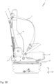
- the vehicle seat 1 is in accordance with Figure 2A shown in a side view, where the rolling up and down mechanism 4 can now also be seen, which in this case is connected to the vehicle seat lower part UT and is preferably arranged and connected to the vehicle seat 1 behind the vehicle seat 1.
- the rolling up and down mechanism is in this case connected to the vehicle seat lower part UT, where it is also conceivable that the rolling up and down mechanism 4 can be connected to the seat part ST, the backrest RL or other elements of the vehicle seat 1.
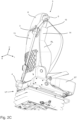
- FIG. 2C The vehicle seat is in accordance with Figures 2A and 2B shown again in a perspective view from behind.
- the deflection element 6 and the deflection unit 5 are designed in such a way that the belt element 3, which can be provided from the winding and unwinding mechanism 4, in the embodiments shown according to the Figure 2A , 2B and 2C shown, by the winding and unwinding mechanism 4 from a position relatively far down with respect to the vehicle seat 1 and behind the vehicle seat 1 upwards and by the deflection element 6 from the top rear to the top front and back down again.
- the belt guide is designed such that no further guide is arranged between the winding and unwinding mechanism 4 and the deflection element 6, i.e. that the belt element 3 is only guided by the winding and unwinding mechanism 4 and the deflection element 6 behind the backrest RL.
- the belt element 3 is arranged on a side of the spacing element 7 facing away from the vehicle seat 1. This means that, viewed in the longitudinal direction L, the spacing element is arranged behind the vehicle seat 1 and the belt element 3 is arranged behind the spacing element 7.
- a further embodiment of the guide of the belt element 3 is shown, wherein a guide element 16 is provided, which is arranged with respect to the belt element 3 or its guide between the winding and unwinding mechanism 4 and the deflection element 6.
- the guide element 16 is connected to the spacing element 7.
- the guide element 16 is connected to the vehicle seat 1, for example the backrest RL.
- the guide element 16 is in this case designed so that a guidance of the belt element 3 and, if necessary, a slight deflection of the belt element 3 is possible.
- the guide element 16 is arranged behind the spacing element 7 as seen in the longitudinal direction L and is connected to it.
- the guide element 16 it would also be possible in principle for the guide element 16 to be arranged between the vehicle seat 1 or the backrest RL and the spacing element 7; this is particularly advantageous if the belt guide of the belt element 3 is such that the belt element 3 is arranged between the vehicle seat 1 and the spacing element 7.
- the spacer element 7 is designed to be elastically deformable, i.e. it is designed as an elastically deformable spacer element 7. It is further preferably provided that in the event that no force acts on the spacer element 7 as a result of a movement of the belt element 3, the spacer element 7 is in a zero position, i.e. is not deformed. However, if tensile forces in particular act on the spacer element 7 as a result of tensile forces acting on the belt element 3, the spacer element 7 is deformed accordingly and is therefore in a deformed state. Because tensile forces in particular act on the spacer element 7, the spacer element 7 is deformed accordingly in the direction of the pull, i.e. preferably in the longitudinal direction L towards the front.
- the forces can be transmitted to the spacing element 7 via the deflection element 6, which leads to the spacing element 7 being deformed forwards.
- the spacing element 7 is deformed forwards.
- the belt element 3 is arranged in the zero position between the vehicle seat 1 and the spacing element 7, and is accordingly moved forward by the spacing element 7 with the deflection element 6.
- FIG. 7 a sectional view of a part of the vehicle seat 1 is shown, wherein the section is such that the spacing element 7, the deflection element 6 and further features of the deflection unit 5 can be seen in the sectional view.
- the deflection element 6 has a slot 20 which is designed and intended to be plugged onto the spacer element 7 so that the spacer element 7 extends partially into the deflection element 6.
- the slot 20 is also preferably designed such that it provides a construction space and a free space for the movement of the spacer element 7 when the spacer element 7 is deformed.
- a first screw connection 19 is provided, which is also intended for the connection between the deflection element 6 and the spacer element 7. The further embodiments of the first screw connection 19 are discussed in more detail in the following figures.
- the spacing element 7 has a layer structure 8 with at least several layers 9.
- the layers 9 are arranged in such a way that they lie on top of one another.
- the respective layers 9 are particularly preferably formed from a leaf spring element.
- the layer structure 8 with the layers 9 is such that the layers 9 can be moved relative to one another when the spacing element 7 is deformed, ie that the layers 9 can be displaced or shifted relative to one another. This is advantageous in order to be able to follow the deformation or movement of the spacing element 7 due to the action of forces.
- the deflection element 6 is shown in more detail.
- the deflection element 6 comprises a guide slot 21, which is provided and designed so that the belt element 3 can pass through the guide slot 21 from the back to the front through the deflection element 6.
- the first screw connection 19 is also shown again, wherein the deflection element 6 further comprises a guide groove 22, which is designed so that the first screw connection 19 is arranged in the guide groove 22.
- the first screw connection 19 is arranged stationary relative to the spacing element 7, so that when the belt element 3 moves in the deflection element 6, for example the guide slot 21, the deflection element 6 moves due to a movement of the guide groove 22 relative to the first screw connection 19, so that the deflection element 6 can be rotated by an angle 23.
- the angle 23 is shown schematically in the Figure 8B The angle 23 is limited by the design or configuration of the guide groove 22, ie, the length of the guide groove 22.
- a securing element 17 is shown in more detail, which is designed to enable or provide the limit angle 10 of the deformation.
- the securing element 17 is such that the layers 9 of the layer structure 8 are connected to one another by the securing element 17.
- the design of the securing element 17 is discussed in more detail below.
- the securing connections 24 are provided, which can particularly preferably also be designed as a screw connection.
- the first screw connection 19 can also function as a securing connection 24.
- the securing connections 24 are such that the layers 9 of the layer structure 8 of the spacing element 7 are connected to one another.
- the securing connection 24 is fitted precisely into corresponding holes 27.
- the holes 27 are preferably designed as through-openings.
- the securing connections 24 are each arranged in a slot 28.
- the slots 28 are designed in such a way that the securing connections 24 can follow the movement of the spacer element 7 as long as the respective end of the slot 28 has been reached. Reaching the end of the slot 28 particularly preferably corresponds to the limit angle 10.
- connection or arrangement of the spacing element 7 on the vehicle seat 1 is shown in more detail in the following figures.
- the spacing element 7 can be connected to the vehicle seat 1, for example the backrest RL, by means of a connecting plate 29.
- a connecting plate 29 By means of the connecting plate 29 provided, further functions can be provided with regard to the rotatability or displaceability of the spacing element 7. This is explained further in the following figures.
- the connecting plate 29 has in particular holes 30 which are provided and designed to be connected to the vehicle seat 1 or the backrest RL with a corresponding element which extends through the hole 30.
- the connecting plate 29 has first holes 31 and second holes 32.
- the first holes 31 are provided above the second holes 32 as seen in the height direction H.
- the first holes 31 are arranged spaced apart from one another in the width direction B. The same also applies to the second holes 32.
- the spacing element 7 is connected to the connecting plate 29 via a first hole 31 and a second hole 32.
- a connecting plate 29 is shown on which the spacing element 7 is arranged. It is provided that on the one hand the spacing element 7 is connected to a first hole 31 and to a second hole 32 or can be connected to the connecting plate 29 via these holes 31, 32. Screw connections 34 are introduced into the holes 31, 32, which are such that the spacing element 7 can be connected to the connecting plate 29.
- the connection with regard to the first hole 31 is such that the spacing element forms a rotation axis 23 here.
- an elongated hole 35 of the spacing element 7 is provided, which is designed so that the elongated hole 35 is movable relative to the screw connection 34.
- the screw connection 34 allows the spacing element 7 to rest so firmly against the connecting plate 29 that movement in the elongated hole 35 or the elongated hole 35 is prevented. Rotation of the spacing element 7 is possible according to the configuration of the elongated hole 35.
- the spacer element 7 can be connected to the connecting plate 29 in any first hole 31 and in any second hole 32.
- the positioning of the spacer element 7 with respect to the connecting plate 29 changes accordingly, as does the positioning of the vehicle seat 1.
- the spacing element 7 is detachably connected to the connecting plate 29 so that during use of the vehicle seat 1 the positioning of the spacing element 7 can be adjusted according to the specifications of a person.
- the positioning of the spacer element 7 is shown as just described. It is provided that the spacer element 7 is released from a first hole 31 and rotated relative to the connecting plate 29 and is connected to a further first hole 31. The connection to the second hole 32 remains unchanged. As can be seen, the result is a rotation or pivoting of the spacer element 7 about the axis of rotation which is formed by the second hole 32.
Landscapes
- Engineering & Computer Science (AREA)
- Mechanical Engineering (AREA)
- Aviation & Aerospace Engineering (AREA)
- Transportation (AREA)
- Automotive Seat Belt Assembly (AREA)
Abstract
Description
- Die vorliegende Erfindung betrifft einen Fahrzeugsitz mit einem Gurtsystem, wobei das Gurtsystem ein Gurtelement und einen Auf- und Abrollmechanismus aufweist, welcher dazu vorgesehen und ausgebildet ist, dass Gurtelement auf- und abzurollen, und wobei das Gurtsystem eine Umlenkeinheit mit einem Umlenkelement aufweist, wobei das Umlenkelement dazu vorgesehen und ausgebildet ist, dass Gurtelement in Richtung einer Person umzulenken.
- Derartige Systeme sind aus dem Stand der Technik gut bekannt, weisen aber grundsätzlich den Nachteil auf, dass sie relativ nah an dem Fahrzeugsitz bzw. mit dem Fahrzeugsitz verbunden sind, sodass eine Umlenkung bzw. eine ergonomische Gurtführung für große und kleine Fahrer gleichermaßen nicht vorgesehen ist. Des Weiteren ist es aus dem Stand der Technik so bekannt, dass die Gurtumlenkungen bzw. die Gurtführungen relativ starr ausgebildet sind, sodass kleineren Bewegungen der Person auf dem Fahrzeugsitz sitzend nicht nachgefolgt werden kann.
- Es ist daher die Aufgabe der vorliegenden Erfindung, einen Fahrzeugsitz bereitzustellen, mittels welchem eine gute Gurtführung und eine Umlenkung des Gurtelements ermöglicht ist uns der Komfort für eine Person, welche auf dem Fahrzeugsitz sitzt, deutlich verbessert werden kann.
- Gelöst wird diese zugrunde liegende Aufgabe durch einen Fahrzeugsitz mit einem Gurtsystem mit den Merkmalen des Patentanspruchs 1.
- Kerngedanke der vorliegenden Erfindung ist es, einen Fahrzeugsitz mit einem Gurtsystem bereitzustellen, wobei das Gurtsystem ein Gurtelement und einen Auf- und Abrollmechanismus aufweist, welche dazu vorgesehen und ausgebildet ist, das Gurtelement auf- und abzurollen, und wobei das Gurtsystem eine Umlenkeinheit mit einem Umlenkelement aufweist, wobei das Umlenkelement dazu vorgesehen ausgebildet ist, das Gurtelement in Richtung einer Person umzulenken. Erfindungsgemäß ist die vorliegende Anmeldung dadurch gekennzeichnet, dass die Umlenkeinheit ein elastisch deformierbares Beabstandungselement aufweist, welches an dem Fahrzeugsitz angeordnet ist und wobei das Umlenkelement derart an den Beabstandungselement angeordnetes, sodass das Umlenkelement von dem Fahrzeugsitz beabstandet ist.
- Dadurch, dass das Umlenkelement von dem Fahrzeugsitz beabstandet ist, bedeutet dies, dass das Umlenkelement zu dem Fahrzeugsitz einen gewissen Abstand aufweist. Das Umlenkelement ist daher mittels des Beabstandungselements insbesondere indirekt mit dem Fahrzeugsitz verbunden.
- Alternativ kann der Begriff Gurtelement auch als ein Gurtband verstanden werden. Ebenso kann der Auf- und Abrollmechanismus als Gurtaufroller oder Gurtrollelement verstanden werden.
- Die Formulierung, dass das Gurtelement in Richtung einer Person umlenkbar ist, bedeutet insbesondere, dass das Gurtelement mittels der Umlenkeinheit und insbesondere mittels des Umlenkelements derart geführt und umgelenkt werden kann, dass das Gurtelement von dem Auf- und Abrollmechanismus in Richtung der Person umgelenkt bzw. geführt werden kann. Insbesondere ist die Person eine Person, welche auf dem Fahrzeugsitz Platz genommen hat und darauf sitzt.
- Wie bereits erwähnt, fungiert das Beabstandungselement als ein Zwischenelement zwischen dem Umlenkelement und dem Fahrzeugsitz.
- Dadurch, dass das Beabstandungselement elastisch deformierbar ausgebildet ist, kann es insbesondere beim Auftreten von Kräften, weiter bevorzugt Zugkräften, dazu führen, dass das elastisch deformierbare Element eben elastisch deformiert werden kann. Dies bedeutet, dass das Beabstandungselement in einem Zustand, in welchem keine Kräfte auf das Beabstandungselement wirken, in seiner Null-Position angeordnet ist. Falls Kräfte, insbesondere Zugkräfte, auf das elastisch deformierbare Beabstandungselement einwirken, kann durch die Kräfte bzw. die einwirkende Kräfte auf das Beabstandungselement das Beabstandungselement elastisch deformiert werden, d. h., dass das Beabstandungselement verbogen bzw. gebogen wird in einen deformierten Zustand. Befindet sich das Beabstandungselement in einem deformierten Zustand, und wirken keine weiteren Kräfte mehr auf das Beabstandungselement, so bewegt sich das Beabstandungselement von dem deformierten Zustand wieder zurück in seine Null-Position.
- Unter den einwirkenden Kräften auf das Beabstandungselement sind insbesondere die Kräfte gemeint, welche mittels bzw. aufgrund der einwirkenden Kräfte auf das Gurtelement auf das Beabstandungselement übertragen werden können. Beispielsweise können Kräfte auf das Gurtelement einwirken bei einer Bewegung der auf dem Fahrzeugsitz sitzenden Person, bei Beschleunigungsmanövern, bei Unfällen und dergleichen. Dadurch, dass sich die Person relativ zu dem Fahrzeugsitz bewegen möchte in diesen Fällen, wird die Bewegung der Person auf das Gurtelement übertragen und entsprechend dann auch auf das Beabstandungselement.
- Es ist daher besonders bevorzugt gemäß der vorliegenden Erfindung vorgesehen, dass eben kleinere Bewegungen der Person auf dem Fahrzeugsitz durch das deformierbare Beabstandungselement gut nachgefolgt werden kann, sodass der Person ein verbesserter Komfort hinsichtlich kleinerer Bewegungen auf dem Fahrzeugsitz bereitgestellt werden kann.
- Aus dem Stand der Technik sind derartige Nachfolgungen des Beabstandungselements nicht vorgesehen, sodass bei Auftreten von Kräften auf das Gurtelement der Auf- und Abrollmechanismus blockiert und dementsprechend auch die Bewegung der Person auf dem Fahrzeugsitz blockiert.
- Dieser Nachteil wird durch die vorliegende Erfindung, insbesondere dem elastisch deformierbaren Beabstandungselement, behoben und eine verbesserte und komfortablere Gurtführung gewährleistet.
- Gemäß einer besonders bevorzugten Ausführungsform ist es dabei vorgesehen, dass das elastisch deformierbare Beabstandungselement derart ausgebildet ist, dass bei einer Deformierung des Beabstandungselements bis zu einem vorbestimmten Grenzwinkel die Deformierung des Beabstandungselement elastisch ist und ab dem Grenzwinkel die Deformierung des Beabstandungselement plastisch ist.
- Beim Erreichen des Grenzwinkels ändert sich eine Belastung des Beabstandungselements von einer Biegebelastung zu einer Zugbelastung, wodurch von einer elastischen Deformierung zu einer plastischen Deformierung gewechselt wird.
- Dadurch, dass das Beabstandungselement ab einem bestimmten Grenzwinkel plastisch deformiert ist bzw. werden kann, hat dies zur Folge, dass bei Auftreten von besonders hohen bzw. kritischen Kräften das Beabstandungselement plastisch deformiert wird, wodurch Kräfte aufgenommen werden können, um Belastungen der auf dem Fahrzeugsitz sitzenden Person aufnehmen zu können. Für kleinere Krafteinwirkungen ist es vorgesehen, dass das Beabstandungselement bis zu dem Grenzwinkel elastisch deformiert werden kann. Die plastische Verformung bzw. Deformierung hat dementsprechend einen Sicherheitsaspekt, insbesondere bei Unfällen, Crashs oder dergleichen.
- Besonders bevorzugt kann es vorgesehen sein, dass der vorbestimmte Grenzwinkel 45° beträgt.
- Insbesondere kann der erfindungsgemäße Fahrzeugsitz, auch insbesondere in Verbindung mit dem vorbestimmten Grenzwinkel, die Anforderungen bzw. Forderungen der SAE J2292 gerecht werden und auch entsprechend den darin definierten Zugversuch gut bestehen.
- Gemäß einer besonders bevorzugten Ausführungsform kann das Beabstandungselement besonders einfach dargestellt werden, wenn das elastisch deformierbare Beabstandungselement schichtartig ausgebildet ist. Besonders bevorzugt weist daher das Beabstandungselement eine Schichtstruktur auf, und wobei bevorzugt die Schichtstruktur aus zumindest zwei Schichten besteht. Dabei kann es bevorzugt vorgesehen sein, dass die Schichten der Schichtstruktur gleichartig ausgebildet sind. Bei mehreren Schichten, d. h. bei mehr als zwei Schichten, kann es vorgesehen sein, dass einzelne Schichten zueinander identisch ausgebildet sind und weiter einzelne oder weitere Schichten andersartig ausgebildet sind. Hierdurch kann es möglich sein, das Beabstandungselement entsprechend den vorliegenden Anforderungen auszubilden.
- Gemäß einer weiteren bevorzugten Ausführungsform kann es vorgesehen sein, dass das Beabstandungselement ein Sicherungselement aufweist, welches die verschiedenen Schichten des Beabstandungselements miteinander verbindet und dabei bevorzugt dazu vorgesehen und ausgebildet ist, bei einem Winkel größer als dem vorbestimmten Grenzwinkel zu versagen und daher die plastische Deformierung des Beabstandungselement zu ermöglichen.
- Weiter kann das elastisch deformierbare Beabstandungselement gemäß einer bevorzugten Ausführungsform derart ausgebildet sein, dass jede Schicht der Schichtstruktur ein Blattfederelement ist. Besonders bevorzugt können die Schichten, wie bereits ausgeführt, unterschiedlich ausgebildet sein, sodass auch die Blattfederelemente zueinander verschieden sein können.
- Gemäß einer weiteren bevorzugten Ausführungsform kann es vorgesehen sein, dass das Beabstandungselement länglich ausgebildet ist. Bevorzugt weist daher das Beabstandungselement eine Erstreckungsrichtung auf, in welche sich die längliche Erstreckung des Beabstandungselements erstreckt. Weiter bedeutet länglich ausgebildet, dass im Vergleich zu der Erstreckung in der Erstreckungsrichtung die Höhenerstreckung sowie die Breitenerstreckung kleiner ausgebildet sind als die Erstreckung in der Erstreckungsrichtung.
- Hierdurch ist es möglich, das Beabstandungselement gut an dem Fahrzeugsitz anzuordnen und entsprechend den Herausforderungen bzw. den Bedarf an den Fahrzeugsitz mit dem Gurtsystem anzupassen.
- Weiter bevorzugt ist es gemäß einer Ausführungsform vorgesehen, dass das Beabstandungselement ein erstes Ende und ein zweites Ende aufweist. Besonders bevorzugt ist das erste Ende mit dem Fahrzeugsitz verbunden. Weiter bevorzugt kann es vorgesehen sein, dass das Umlenkelement an dem zweiten Ende des Beabstandungselement angeordnet ist. Bevorzugt ist es vorgesehen, dass das Beabstandungselement fest mit dem Fahrzeugsitz verbunden ist.
- Um den Komfort für eine auf dem Fahrzeugsitz sitzenden Person weiter verbessern zu können, ist es besonders bevorzugt vorgesehen, dass das elastisch deformierbare Beabstandungselement gegenüber dem Fahrzeugsitz verlagert und/oder drehbar angeordnet ist. Jedoch kann es für eine Person möglich sein, die Position des Umlenkelements hinsichtlich des Fahrzeugsitzes einzustellen, sodass das Umlenkelement an der korrekten Position für den Fahrer angeordnet ist. Wie erwähnt, kann das elastisch deformierbare Beabstandungselement gegenüber dem Fahrzeugsitz verlagert werden. Beispielsweise ist es hier möglich, eine Führung mittels einer oder mehrerer Nut- und Federelemente bereitzustellen, wobei bevorzugt die Nut an dem Beabstandungselement und die Feder an dem Fahrzeugsitz angeordnet ist. Alternativ oder kumulativ kann es vorgesehen sein, dass das elastisch deformierbare Beabstandungselement gegenüber dem Fahrzeugsitz drehbar angeordnet ist. Dies kann bedeuten, dass durch ein Drehen des Beabstandungselements das Beabstandungselement entsprechend ausgerichtet werden kann.
- Besonders bevorzugt kann es vorgesehen sein, dass eine Verlagerung bzw. eine Drehung des Beabstandungselements gegenüber dem Fahrzeugsitz eine lösbare Verbindung darstellt, wobei die Verbindung zwischen dem Beabstandungselement und dem Fahrzeugsitz eben gelöst werden kann und auch das Beabstandungselement wieder fest mit dem Fahrzeugsitz verbunden werden kann, insbesondere nach einer Verlagerung und/oder Drehung des Beabstandungselements.
- Durch die feste Verbindung des Beabstandungselements zu dem Fahrzeugsitz kann eine ungewollte Bewegung des Beabstandungselements verhindert werden, um eine entsprechend gute Positionierung des Umlenkelement gegenüber dem Fahrzeugsitz zu haben und eine gute Krafteinwirkung bzw. Krafteinlenkung auf das Umlenkelement bzw. den Beabstandungselement gewährleistet werden kann.
- Besonders vorteilhaft kann das elastisch deformierbare Beabstandungselement bereitgestellt werden, wenn das Beabstandungselement aus einem oder mehreren Metallen und/oder Metalllegierungen besteht. Besonders bevorzugt kann es vorgesehen sein, dass das Beabstandungselement aus einem korrosionsbeständigen Federstahl, insbesondere einem nicht-rostenden Federstah, besteht bzw. hergestellt ist. Durch das Ausbilden des Beabstandungselements aus Metallen bzw. Metalllegierungen kann eine gute Balance zwischen einer Deformierung und einer Stabilität bzw. Steifigkeit bereitgestellt werden.
- Das Material des korrosionsbeständigen Federstahls ist dabei besonders bevorzugt, da eben genau dieses die geforderten Anforderungen an das Beabstandungselement bereitstellen kann. Ebenso ist Edelstahl leicht verfügbar und kostentechnisch weiterhin günstig zu erwerben.
- Zur weiteren Komforterhöhung für einen Benutzer des Fahrzeugsitz bzw. der Person auf dem Fahrzeugsitz kann es gemäß einer besonders bevorzugten Ausführungsform vorgesehen sein, dass das Umlenkelement drehbar mit dem elastisch deformierbaren Beabstandungselement verbunden ist. Dies bedeutet, dass das Umlenkelement drehbar mit dem Beabstandungselement verbunden ist, wodurch das Gurtelement, welches sich durch das Umlenkelement erstreckt bzw. mittels des Umlenkelements umgelenkt werden kann, durch Beanspruchungen zur Seite, also durch Krafteinwirkung senkrecht zu einer Zugkrafteinwirkung, einer Auslenkung des Gurtelements gut nachgefolgt werden kann.
- Weiter kann es gemäß einer bevorzugten Ausführungsform vorgesehen sein, dass der Fahrzeugsitz eine Rückenlehne aufweist. Weiter bevorzugt ist es vorgesehen, dass das elastisch deformierbare Beabstandungselement mit der Rückenlehne verbunden ist. Bevorzugt ist er diese Verbindung zwischen dem Beabstandungselement und der Rückenlehne derart, dass das Beabstandungselement an einem rückwärtigen Teil der Rückenlehne, an einem seitlichen Teil der Rückenlehne, und/oder an einem oberen Teil der Rückenlehne angeordnet ist.
- Dies bedeutet, dass das Beabstandungselement und dementsprechend auch das Umlenkelement entsprechend positioniert werden können, sodass möglichst eine gute Positionierung des Gurtelements hinsichtlich der auf dem Fahrzeugsitz sitzenden Person möglich ist. Das Beabstandungselement sollte derart angeordnet sein, dass es im Fahrbetrieb bzw. bei der Benutzung des Fahrzeugsitzes möglichst nicht störend auf die Person wirken kann. Besonders bevorzugt ist es vorgesehen, dass das Beabstandungselement an dem rückwärtigen Teil der Rückenlehne angeordnet ist. Dies ist besonders dann vorteilhaft, wenn auch der Auf- und Abrollmechanismus an dem rückwärtigen Teil der Rückenlehne angeordnet ist oder hinter der Rückenlehne angeordnet ist. Eine Befestigung an einem seitlichen Teil der Rückenlehne ist dabei abhängig von den Platzverhältnissen nach links bzw. nach rechts im Fahrzeug bzw. hinsichtlich des Fahrzeugsitzes. Gleiches gilt natürlich in ähnlicher Weise für den oberen Teil der Rückenlehne, wobei es bevorzugt vorgesehen sein kann, dass eine Kopfstütze vorgesehen ist. Für den Fall, dass diese Kopfstütze vorgesehen ist, ist es besonders bevorzugt derart, dass das Umlenkelement auf einer Höhe mit der Kopfstütze angeordnet sein kann.
- Gemäß einer weiteren bevorzugten Ausführungsform kann es vorgesehen sein, dass der Auf- und Abrollmechanismus hinter der Rückenlehne angeordnet ist. Weiter bevorzugt kann es vorgesehen sein, dass der Auf- und Abrollmechanismus an einem Sitzteil des Fahrzeugsitzes und/oder an einem Fahrzeugsitzunterteil angeordnet ist. Das Sitzteil kann dementsprechend als das Element des Fahrzeugsitzes verstanden werden, auf welchem die Person sitzen kann. Das Fahrzeugsitzunterteil kann dabei derart verstanden werden, dass dies ein Trageteil darstellt, auf welchen der Fahrzeugsitz an sich angeordnet ist.
- Durch diese Anordnung des Auf- und Abrollmechanismuses ist es dementsprechend möglich, dass mit der Bewegung des Fahrzeugsitzes bei einer Längsverstellung, bei einer Breitenverstellung und/oder einer Höhenverstellung der Auf- und Abrollmechanismus mit dem Fahrzeugsitz bewegt wird bzw. mit dem entsprechenden Element. Dies gilt auch hinsichtlich einer Drehung des Fahrzeugsitzes. Dies bedeutet, dass der Auf- und Abrollmechanismus sich gleichermaßen mit dem Fahrzeugsitz bzw. dem Fahrzeugsitzunterteil bewegen kann, sodass eben dieser Mechanismus entsprechend positioniert werden kann.
- Gemäß einer weiteren bevorzugten Ausführungsform kann es vorgesehen sein, dass zwischen dem Auf- und Abrollmechanismus und dem Umlenkelement ein Führungselement angeordnet ist zum Führen des Gurtelements. Dies bedeutet, dass das Führungselement dazu vorgesehen und ausgebildet ist, das entsprechend vorgesehene Gurtelement zu führen, d. h., in diesem Falle zu dem Umlenkelement hinzuführen.
- Gemäß einer weiteren bevorzugten Ausführungsform kann es vorgesehen sein, dass das Führungselement zwischen dem Fahrzeugsitz und dem elastisch deformierbaren Beabstandungselement angeordnet ist. Hierdurch ist es möglich, den Platz zwischen dem Fahrzeugsitz und dem Beabstandungselement bzw. zwischen der Rückenlehne und dem Beabstandungselement effizient auszunutzen.
- Alternativ kann es gemäß einer weiteren bevorzugten Ausführungsform vorgesehen sein, dass das Führungselement auf einer dem Fahrzeugsitz abgewandten Seite des elastisch deformierbaren Beabstandungselements angeordnet ist. Dadurch kann das entsprechende Führungselement besonders vorteilhaft ausgebildet werden, um besonders gut die Führung des Gurtelements gewährleisten zu können.
- Gemäß einer alternativen Ausführungsform kann es vorgesehen sein, dass das Gurtelement zwischen dem Fahrzeugsitz und dem elastisch deformierbaren Beabstandungselement angeordnet ist, wobei auf ein Führungselement verzichtet werden kann. Bei einem Verzicht auf das Führungselement und der Anordnung des Gurtelements zwischen Beabstandungselement und dem Fahrzeugsitz ist eine Führung des Gurtelement bereits inhärent vorgegeben.
- Weiterführende Ausgestaltungen und Ausbildungen in den Ausführungsformen untereinander sind auf die weiteren Ausführungen anwendbar und sind untereinander frei kombinierbar, sofern sie nicht gegenläufigen Ausführungsformen entsprechen.
- Weitere vorteilhafte Ausführungsformen ergeben sich aus den Unteransprüchen.
- Weitere Ziele, Vorteile und Zweckmäßigkeiten der vorliegenden Erfindung sind der nachfolgenden Beschreibung in Verbindung mit den Zeichnungen zu entnehmen.
- Die Erfindung wird nachfolgend in Zusammenhang mit den Figuren näher dargestellt.
- Es zeigen:
- Fig. 1A
- einen Fahrzeugsitz des Standes der Technik;
- Fig. 1B
- einen erfindungsgemäßen Fahrzeugsitz;
- Fig. 1C
- einen Vergleich der Fahrzeugsitze gemäß den
Figuren 1A und 1B ; - Fig. 2A
- den Fahrzeugsitz gemäß einer bevorzugten Ausführungsform in einer Vorderansicht;
- Fig. 2B
- den Fahrzeugsitz gemäß
Figur 2A in einer Seitenansicht; - Fig. 2C
- den Fahrzeugsitz gemäß
Figur 2A in einer perspektivischen Ansicht von hinten; - Fig. 3A
- einen Fahrzeugsitz gemäß einer Ausführungsform in einer Vorderansicht;
- Fig. 3B
- den Fahrzeugsitz gemäß
Figur 3A in einer Rückansicht; - Fig. 4A
- einen Fahrzeugsitz gemäß einer Ausführungsform in einer Vorderansicht;
- Fig. 4B
- den Fahrzeugsitz gemäß
Figur 4A in einer Rückansicht; - Fig. 5A
- einen Fahrzeugsitz gemäß einer Ausführungsform in einer Vorderansicht;
- Fig. 5B
- den Fahrzeugsitz gemäß
Figur 5A in einer Rückansicht; - Fig. 6A
- das Beabstandungselement in einer Null-Position;
- Fig. 6B
- das Beabstandungselement in einer deformierten Position;
- Fig. 6C
- das Beabstandungselement in einer deformierten Position;
- Fig. 7
- eine Schnittdarstellung der Umlenkeinheit;
- Fig. 8A
- eine Seitenansicht der Umlenkeinheit;
- Fig. 8B
- eine Schnittansicht entlang B-B;
- Fig. 8C
- eine Schnittansicht entlang C-C;
- Fig. 8D
- eine Schnittansicht entlang D-D;
- Fig. 9A
- eine Darstellung einer Verbindungsplatte;
- Fig. 9B
- die Verbindungsplatte mit montiertem Beabstandungselement;
- Fig. 9C
- verschiedene Drehpositionen des Beabstandungselements;
- Fig. 9D
- verschiedene Verlagerungspositionen des Beabstandungselements.
- In den Figuren sind gleiche Bauteile jeweils mit den entsprechenden Bezugszeichen zu verstehen. Zur besseren Übersichtlichkeit können in manchen Figuren Bauteile nicht mit einem Bezugszeichen versehen sein, die jedoch an anderer Stelle bezeichnet worden sind.
- Gemäß der
Figur 1A ist ein Fahrzeugsitz 1 gemäß dem bekannten Stand der Technik dargestellt, wobei der Fahrzeugsitz 1 eine Rückenlehne RL aufweist, an welcher eine Umlenkeinheit 5 mit einem Umlenkelement 6 gezeigt ist. Auf ein Gurtsystem 2 mit einem Gurtelement 3 sowie dem Auf- und Abrollmechanismus 4 wurde an dieser Stelle zu Übersichtlichkeit verzichtet. - Wie gemäß der
Figur 1A zu erkennen ist, ist das Umlenkelement 6 relativ nahe bei der Rückenlehne RL angeordnet, sodass eine ergonomische bzw. komfortable Führung und Umlenkung eines Gurtelements 3 nicht bereitgestellt werden kann. - Demgegenüber ist in der
Figur 1B ein Fahrzeugsitz 1 gemäß einer bevorzugten Ausführungsform der Erfindung gezeigt, wobei an dem Fahrzeugsitz 1 wiederum das Umlenkelement 6 der Umlenkeinheit 5 an der Rückenlehne RL angeordnet ist. Das Umlenkelement 6 ist dabei mittels eines Beabstandungselements 7 mit der Rückenlehne RL verbunden. Durch das Beabstandungselement 7 ist es möglich, das Umlenkelement 6, wie gezeigt, relativ weit von der Rückenlehne RL beabstandet anzuordnen. - Ein Vergleich zwischen dem Fahrzeugsitz 1 gemäß dem Stand der Technik und dem Fahrzeugsitz 1 gemäß der vorliegenden Erfindung ist in der
Figur 1C gezeigt, wobei deutlich zu erkennen ist, wie der Unterschied der Anordnung des jeweiligen Umlenkelements 6 zu der Rückenlehne RL bzw. dem Fahrzeugsitz 1 ist. - Durch die weiter außen liegende Anordnung des Umlenkelements 6 ist eine bessere bzw. optimalere Ergonomie des Gurtsystems 2 bzw. eine Führung des Gurtelements 3 möglich. Besonders bevorzugt im Vergleich zu dem Stand der Technik aus der
Figur 1A kann in totalen Zahlen das Umlenkelement 6 gegenüber dem Stand der Technik um mehr als 100 mm in einer Breitenrichtung B und mehr als 50 mm in einer Höhenrichtung H weiter außen hinsichtlich des Fahrzeugsitzes 1 angeordnet werden. Besonders bevorzugt kann das Umlenkelement 6 um bis zu 130 mm in der Breitenrichtung B und bis zu 80 mm in der Höhenrichtung H weiter außen gegenüber dem Stand der Technik angeordnet werden. - In den nachfolgenden Figuren werden weitere Ausgestaltungen, Ausbildungen und Eigenschaften der vorliegenden Erfindung weiter näher dargestellt.
- In der
Figur 2A ist ein Fahrzeugsitz 1 gemäß einer bevorzugten Ausführungsform von vorne dargestellt, in derFigur 2B in einer Seitendarstellung und in derFigur 2C in einer perspektivischen Darstellung von hinten. - Wie zu erkennen ist, umfasst der Fahrzeugsitz 1 gemäß einer bevorzugten Ausführungsform eine Rückenlehne RL, ein Sitzteil ST und ein Fahrzeugsitzunterteil UT, wobei das Fahrzeugsitzunterteil UT unterhalb des Sitzteils ST angeordnet ist, und wobei das Sitzteil ST mit dem Fahrzeugsitzunterteil UT verbunden ist. Das Fahrzeugsitzunterteil UT umfasst weiter bevorzugt eine Feder- und/oder Dämpfungseinheit 18, welche in diesem Beispiel lediglich beispielhaft gekennzeichnet ist und auf Federeinheiten und Dämpfungseinheiten an sich verzichtet worden ist.
- Weiter kann der Fahrzeugsitz 1 eine Kopfstütze K umfassen.
- Weiter ist das Gurtsystem 2 mit einem Gurtelement 3 dargestellt, wobei das Gurtsystem 2 einen aus dem Stand der Technik bekannt kannten 3-Punktgurt darstellen kann. Das Umlenkelement 6 der Umlenkeinheit 5 ist dabei mittels des Beabstandungselements 7 mit dem Fahrzeugsitz 1, hier mit der Rückenlehne RL, verbunden und von diesem beabstandet. Das Umlenkelement 6 ist dabei dazu vorgesehen und ausgebildet, das Gurtelement 3 entsprechend umzulenken und zu der Person hinzuführen. Die Person ist hier nicht dargestellt, kann aber auf dem Sitzteil ST bzw. dem Fahrzeugsitz 1 sitzend vorgestellt werden. Auf die näheren Ausführungen hinsichtlich des der 3-Punktgurtes kann verzichtet werden.
- In der
Figur 2B ist der Fahrzeugsitz 1 gemäß derFigur 2A in einer Seitenansicht dargestellt, wobei nun auch der Auf- und Abrollmechanismus 4 zu erkennen ist, welcher vorliegend mit dem Fahrzeugsitzunterteil UT verbunden ist und dabei bevorzugt hinter dem Fahrzeugsitz 1 mit dem Fahrzeugsitz 1 angeordnet und verbunden ist. Der Auf- und Abrollmechanismus ist dabei vorliegend mit dem Fahrzeugsitzunterteil UT verbunden, wobei es auch denkbar ist, dass der Auf- und Abrollmechanismus 4 mit dem Sitzteil ST, der Rückenlehne RL oder anderen Elementen des Fahrzeugsitzes 1 verbunden sein kann. - In der
Figur 2C ist der Fahrzeugsitz gemäß denFiguren 2A und2B nochmals in einer perspektivischen Ansicht von hinten dargestellt. - Besonders bevorzugt ist das Umlenkelement 6 und die Umlenkeinheit 5 dabei derart ausgebildet, das Gurtelement 3, welches aus dem Auf- und Abrollmechanismus 4 heraus bereitgestellt werden kann, in den gezeigten Ausführungsformen gemäß der
Figur 2A ,2B und2C dargestellt, von dem Auf- und Abrollmechanismus 4 von einer Position relativ weit unten hinsichtlich des Fahrzeugsitzes 1 und hinter dem Fahrzeugsitz 1 nach oben und von dem Umlenkelement 6 von oben hinten nach oben vorne und wieder nach unten zu führen. - Die verschiedenen Möglichkeiten bzw. Ausführungsformen hinsichtlich der Führung des Gurtelements 3 ist in den nachfolgenden Figuren näher dargestellt.
- In den
Figuren 3A und 3B ist die Gurtführung derart ausgebildet, dass zwischen dem Auf- und Abrollmechanismus 4 und dem Umlenkelement 6 keine weitere Führung angeordnet ist, d. h., dass das Gurtelement 3 lediglich durch den Auf- und Abrollmechanismus 4 sowie dem Umlenkelement 6 hinter der Rückenlehne RL geführt ist. - Dabei ist es vorgesehen, dass das Gurtelement 3 auf einer dem Fahrzeugsitz 1 abgewandten Seite des Beabstandungselements 7 angeordnet ist. Das bedeutet, dass in der Längsrichtung L gesehen das Beabstandungselement hinter dem Fahrzeugsitz 1 angeordnet ist und das Gurtelement 3 hinter dem Beabstandungselement 7.
- In den
Figuren 4A und 4B ist eine alternative Ausführungsform zu denFiguren 3A und 3B dargestellt, wobei nun das Gurtelement 3 nicht hinter dem Beabstandungselement 7 angeordnet ist, sondern derart, dass das Gurtelement 3 zwischen dem Fahrzeugsitz 1 und dem Beabstandungselement 7 angeordnet ist. Dies bedeutet, dass das Gurtelement 3 in der Längsrichtung L gesehen hinter dem Fahrzeugsitz 1 angeordnet ist und das Beabstandungselement 7 hinter dem Gurtelement 3. - Gemäß den
Figuren 5A und 5B ist eine weitere Ausführungsform der Führung des Gurtelements 3 dargestellt, wobei ein Führungselement 16 vorgesehen ist, welches hinsichtlich des Gurtelements 3 bzw. dessen Führung zwischen dem Auf- und Abrollmechanismus 4 sowie dem Umlenkelement 6 angeordnet ist. Gemäß der vorliegendenFigur 5B ist es vorgesehen, dass das Führungselement 16 mit dem Beabstandungselement 7 verbunden ist. Grundsätzlich ist es auch möglich, dass das Führungselement 16 mit dem Fahrzeugsitz 1, beispielsweise der Rückenlehne RL, verbunden ist. Das Führungselement 16 ist dabei derart ausgebildet, dass eine Führung des Gurtelements 3 und gegebenenfalls eine geringe Ablenkung des Gurtelements 3 möglich ist. - In der vorliegenden Ausführungsform gemäß der
Figur 5B ist es vorgesehen, dass das Führungselement 16 in Längsrichtung L gesehen hinter dem Beabstandungselement 7 angeordnet ist und mit diesem verbunden ist. - Es wäre auch grundsätzlich möglich, dass das Führungselement 16 zwischen dem Fahrzeugsitz 1 bzw. der Rückenlehne RL und dem Beabstandungselement 7 angeordnet ist, dies ist insbesondere dann vorteilhaft, wenn die Gurtführung des Gurtelements 3 derart ist, dass das Gurtelement 3 zwischen dem Fahrzeugsitz 1 und dem Beabstandungselement 7 angeordnet ist.
- In den weiteren Figuren wird nun die Funktionsweise des Beabstandungselements 7 sowie die Ausgestaltungen bzw. Ausführungen hinsichtlich des Beabstandungselements 7 näher dargestellt.
- Erfindungsgemäß ist es vorgesehen, dass das Beabstandungselement 7 elastisch deformierbar ausgebildet ist, also als ein elastisch deformierbares Beabstandungselement 7 ausgebildet ist. Weiter bevorzugt ist es vorgesehen, dass für den Fall, dass keine Kraft durch eine Bewegung des Gurtelements 3 auf das Beabstandungselement 7 einwirkt, sich das Beabstandungselement 7 in einer Null-Position befindet, d. h., nicht deformiert ist. Wirken jedoch insbesondere Zugkräfte durch Zugkräfte, welche auf das Gurtelement 3 einwirken, auf das Beabstandungselement 7, so wird das Beabstandungselement 7 entsprechend deformiert und befindet sich demnach in einem deformierten Zustand. Dadurch, dass insbesondere Zugkräfte auf das Beabstandungselement 7 einwirken, wird das Beabstandungselement 7 entsprechend in Richtung des Zuges deformiert, d. h. bevorzugt in Längsrichtung L nach vorne.
- In der
Figur 6A ist das Beabstandungselement 7 in der Null-Position dargestellt. Das bedeutet, dass keine Kräfte auf das Beabstandungselement 7 einwirken, da keine Kräfte auf das Gurtelement 3 einwirken. - In der
Figur 6B hingegen ist das Beabstandungselement 7 in einem deformierten Zustand dargestellt, wobei durch Einwirkung von Kräften auf das Gurtelement 3 in der Längsrichtung - L nach vorne dementsprechend auch über das Umlenkelement 6 die Kräfte auf das Beabstandungselement 7 übertragen werden können, was dazu führt, dass das Beabstandungselement 7 nach vorne deformiert wird. Weiter ist in der
Figur 6B die Ausführungsform dargestellt, dass das Beabstandungselement 7 nach vorne deformiert wird. Weiter ist in derFigur 6B die Ausführungsform dargestellt, dass das Gurtelement 3 in der Null-Position zwischen dem Fahrzeugsitz 1 und dem Beabstandungselement 7 angeordnet ist, und dementsprechend von dem Beabstandungselement 7 nach vorne bewegt wird mit dem Umlenkelement 6. - In der
Figur 6C ist die Ausgangssituation wie in derFigur 6B , jedoch ist das Gurtelement 3 hier in diesem Falle hinter dem Beabstandungselement 7 angeordnet, sodass sich das Gurtelement 3 entsprechend mit dem Beabstandungselement 7 bewegt. - In der
Figur 7 ist eine Schnittdarstellung eines Teils des Fahrzeugsitzes 1 dargestellt, wobei der Schnitt derart ist, dass das Beabstandungselement 7, das Umlenkelement 6 und weitere Merkmale der Umlenkeinheit 5 in der Schnittdarstellung zu sehen sind. - Besonders bevorzugt ist es vorgesehen, dass das Umlenkelement 6 einen Schlitz 20 aufweist, welcher dazu ausgebildet und vorgesehen ist, auf das Beabstandungselement 7 aufgesteckt zu werden, so dass sich das Beabstandungselement 7 teilweise in das Umlenkelement 6 hinein erstreckt. Weiter bevorzugt ist der Schlitz 20 derart ausgebildet, dass dieser einen Bauraum und einen Freiraum für die Bewegung des Beabstandungselements 7 bei Deformation des Beabstandungselements 7 bereitstellt. Weiter ist es vorgesehen, dass eine erste Schraubverbindung 19 vorgesehen ist, welche ebenfalls zur Verbindung zwischen dem Umlenkelement 6 und dem Beabstandungselement 7 vorgesehen ist. Auf die weiteren Ausführungen der ersten Schraubverbindung 19 wird in den nachfolgenden Figuren näher eingegangen.
- Weiter ist zu erkennen, dass das Beabstandungselement 7 eine Schichtstruktur 8 aufweist, mit zumindest mehreren Schichten 9. Dabei sind die Schichten 9 derart angeordnet, dass diese übereinanderliegend sind. Besonders bevorzugt sind die jeweiligen Schichten 9 aus einem Blattfederelement ausgebildet. Hierdurch ist es möglich, eine besonders einfache Konstruktion des Beabstandungselement 7 bereitzustellen. Insbesondere ist die Schichtstruktur 8 mit den Schichten 9 derart, dass die Schichten 9 bei einer Deformierung des Beabstandungselements 7 zueinander bewegbar sind, d. h., dass sich die Schichten 9 zueinander verlagern bzw. verschieben können. Dies ist dahingehend vorteilhaft, um der Deformation bzw. der Bewegung des Beabstandungselements 7 nachfolgend zu können, aufgrund der Einwirkung von Kräften.
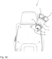
- In der
Figur 8A ist nochmals das Beabstandungselement 7 mit dem Umlenkelement 6 dargestellt, wobei auf den Fahrzeugsitz 1 bzw. das Gurtsystem 2 mit dem Gurtelement 3 verzichtet worden ist. In derFigur 8A sind weitere Schnitte dargestellt, einmal ein Schnitt B-B, welche in derFigur 8B dargestellt ist, 1chnitt C-C, welcher in derFigur 8C dargestellt ist, und einen Schnitt D-D, welcher in derFigur 8D dargestellt ist. - In der
Figur 8B ist das Umlenkelement 6 nochmals näher dargestellt. Insbesondere umfasst das Umlenkelement 6 einen Führungsschlitz 21, welcher dazu vorgesehen und ausgebildet ist, dass das Gurtelement 3 durch den Führungsschlitz 21 hindurch von hinten nach vorne durch das Umlenkelement 6 hindurchreichen kann. Weiter ist nochmals die erste Schraubverbindung 19 dargestellt, wobei das Umlenkelement 6 weiter eine Führungsnut 22 aufweist, welche dazu vorgesehen ausgebildet ist, dass die erste Schraubverbindung 19 in der Führungsnut 22 angeordnet ist. Die erste Schraubverbindung 19 ist dabei ortsfest gegenüber dem Beabstandungselement 7 angeordnet, sodass sich bei einer Bewegung des Gurtelements 3 in dem Umlenkelement 6, beispielsweise dem Führungsschlitz 21, bewegt, sich das Umlenkelement 6 durch eine Bewegung der Führungsnut 22 gegenüber der ersten Schraubverbindung 19 bewegt, sodass das Umlenkelement 6 um einen Winkel 23 gedreht werden kann. Der Winkel 23 ist dabei schematisch in derFigur 8B dargestellt. Der Winkel 23 ist dabei durch die Ausbildung bzw. Ausgestaltung der Führungsnut 22 limitiert, d. h., der Länge der Führungsnut 22. - In den
Figuren 8C und 8D ist ein Sicherungselement 17 näher dargestellt, welches dazu ausgebildet vorgesehen ist, den Grenzwinkel 10 der Deformierung zu ermöglichen bzw. bereitzustellen. Das Sicherungselement 17 ist dabei derart, dass durch das Sicherungselement 17 die Schichten 9 der Schichtstruktur 8 miteinander verbunden sind. Auf die Ausgestaltung des Sicherungselement 17 wird im Folgenden näher eingegangen. Wie zu erkennen ist, ist gemäß derFigur 8C und 8D die Sicherungsverbindungen 24 vorgesehen, welche besonders bevorzugt auch als eine Schraubverbindung ausgebildet sein können. Die erste Schraubverbindung 19 kann dabei auch als eine Sicherungsverbindung 24 fungieren. Die Sicherungsverbindungen 24 sind dabei derart, dass die Schichten 9 der Schichtstruktur 8 des Beabstandungselements 7 miteinander verbunden sind. Auf der einen Seite bzw. der ersten Seite 25 des Beabstandungselements 7 sind die Sicherungsverbindung in 24 passgenau in entsprechende Löcher 27 eingebracht. Die Löcher 27 es sind dabei bevorzugt als Durchgangsöffnungen ausgebildet. Auf der anderen bzw. der zweiten Seite 26 des Beabstandungselements 7, wie in derFigur 8D dargestellt, sind die Sicherungsverbindungen 24 jeweils in einem Langloch 28 angeordnet. Bei einer Deformation des Beabstandungselements 7 verschieben sich entsprechend die Schichtstrukturen zueinander, sodass auch die Sicherungsverbindungen 24 eine entsprechende Bewegung erfahren, wobei die Sicherungsverbindungen 24 aufgrund der Ausgestaltung bzw. dem Vorsehen von Langlöchern 28 auf der zweiten Seite 26 dieser Bewegung gut nachfolgend können. Die Langlöcher 28 es sind dabei derart ausgebildet, dass die Sicherungsverbindungen 24 solange der Bewegung des Beabstandungselements 7 nachfolgend können, ist das jeweilige Ende des Langlochs 28 erreicht worden ist. Das Erreichen des Endes des Langloches 28 entspricht besonders bevorzugt dem Grenzwinkel 10. - In den nachfolgenden Figuren ist die Verbindung bzw. Anordnung des Beabstandungselements 7 an dem Fahrzeugsitz 1 im Näheren dargestellt.
- Besonders bevorzugt ist es vorgesehen, dass das Beabstandungselement 7 mittels einer Verbindungsplatte 29 mit dem Fahrzeugsitz 1, beispielsweise der Rückenlehne RL, verbunden werden kann. Mittels der vorgesehenen Verbindungsplatte 29 können weitere Funktionen hinsichtlich der Drehbarkeit bzw. Verlagerbarkeit des Beabstandungselements 7 bereitgestellt werden. Dies wird in den nachfolgenden Figuren weiter erläutert.
- Die Verbindungsplatte 29 weist insbesondere Löcher 30 auf, welche dazu vorgesehen und ausgebildet sind, mit einem entsprechenden Element, welches sich durch das Loch 30 hindurch erstreckt, mit dem Fahrzeugsitz 1 bzw. der Rückenlehne RL verbunden zu werden.
- Weiter weist die Verbindungsplatte 29 erste Löcher 31 und zweite Löcher 32 auf. Besonders bevorzugt sind die ersten Löcher 31 in der Höhenrichtung H gesehen oberhalb der zweiten Löcher 32 vorgesehen. Die ersten Löcher 31 sind in der Breitenrichtung B voneinander beabstandet angeordnet. Gleiches gilt auch für die zweiten Löcher 32.
- Besonders bevorzugt ist das Beabstandungselement 7 dabei jeweils mit einem ersten Loch 31 und einem zweiten Loch 32 mit der Verbindungsplatte 29 verbunden.
- Je nachdem, mit welchen Löchern 31, 32 das Beabstandungselement 7 mit der Verbindungsplatte 29 verbunden ist, können verschiedene Positionen des Beabstandungselements 7 hinsichtlich der Verbindungsplatte 29 und dementsprechend hinsichtlich des Fahrzeugsitzes 1 bzw. der Rückenlehne RL realisiert werden.
- Gemäß der vorliegenden
Figur 9B ist eine Verbindungsplatte 29 gezeigt, an welcher das Beabstandungselement 7 angeordnet ist. Dabei ist es vorgesehen, dass einerseits das Beabstandungselement 7 mit einem ersten Loch 31 und mit einem zweiten Loch 32 verbunden ist bzw. über diese Löcher 31, 32 mit der Verbindungsplatte 29 verbindbar ist. In die Löcher 31,32 sind Schraubverbindungen 34 eingebracht, welche derart sind, dass das Beabstandungselement 7 mit der Verbindungsplatte 29 verbunden werden können. Die Verbindung hinsichtlich des ersten Loches 31 ist dabei derart, dass das Beabstandungselement eine Drehachse 23 hier ausbildet. Weiter bevorzugt ist ein Langloch 35 des Beabstandungselements 7 vorgesehen, welches dazu vorgesehen ausgebildet ist, dass das Langloch 35 gegenüber der Schraubverbindung 34 bewegbar ist. Es ist jedoch auch bevorzugt vorgesehen, dass die Schraubverbindung 34 so fest das Beabstandungselement 7 derart an die Verbindungsplatte 29 anliegen lässt, sodass eine Bewegung im Langloch 35 bzw. des Langloch 35 verhindert wird. Eine Drehung des Beabstandungselements 7 ist entsprechend den Ausgestaltungen des Langloches 35 möglich. - Grundsätzlich ist es denkbar, dass das Beabstandungselement 7 in einem beliebigen ersten Loch 31 und in einem beliebigen zweiten Loch 32 an die Verbindungsplatte 29 verbunden werden kann. Je nachdem, welche Löcher 31, 32 zur Befestigung des Beabstandungselement 7 an der Verbindungsplatte 29 ausgebildet sind, ändert sich entsprechend die Positionierung des Beabstandungselements 7 hinsichtlich der Verbindungsplatte 29 dementsprechend ebenso gegenüber dem Fahrzeugsitz 1.
- Ebenso ist es vorgesehen, dass das Beabstandungselement 7 lösbar mit der Verbindungsplatte 29 verbunden ist, sodass während eines Gebrauchs des Fahrzeugsitzes 1 die Positionierung des Beabstandungselements 7 entsprechend den Vorgaben einer Person angepasst werden kann.
- Gemäß der
Figur 9C ist die Positionierung des Beabstandungselement 7, wie gerade beschrieben, dargestellt. Dabei ist es vorgesehen, dass das Beabstandungselement 7 aus einem ersten Loch 31 gelöst wird und gegenüber der Verbindungsplatte 29 gedreht wird und mit einem weiteren ersten Loch 31 verbunden wird. Die Verbindung mit dem zweiten Loch 32 bleibt unverändert. Wie zu erkennen ist, ist das Resultat eine Drehung bzw. Verschwenkung des Beabstandungselements 7 um die Drehachse, welche durch das zweite Loch 32 ausgebildet ist. - Gemäß der
Figur 9D ist eine weitere Situation dargestellt, wobei die Positionierung des Beabstandungselements 7 dahingehend geändert worden ist, dass sowohl die Position bzw. die Verbindung zu einem ersten Loch 31 und zu einem zweiten Loch 32 geändert worden ist. - Sämtliche in den Anmeldungsunterlagen offenbarten Merkmale werden als erfindungswesentlich beansprucht, sofern sie einzeln oder in Kombination gegenüber dem Stand der Technik neu sind. Alle aufgeführten Merkmale können miteinander in beliebiger Weise kombiniert werden.
-
- 1
- Fahrzeugsitz
- 2
- Gurtsystem
- 3
- Gurtelement
- 4
- Auf- und Abrollmechanismus
- 5
- Umlenkeinheit
- 6
- Umlenkelement
- 7
- Beabstandungselement
- 8
- Schichtstruktur
- 9
- Schicht
- 10
- Grenzwinkel
- 11
- erstes Ende des Beabstandungselements
- 12
- zweites Ende des Beabstandungselements
- 13
- rückwärtiges Teil
- 14
- seitliches Teil
- 15
- oberes Teil
- 16
- Führungselement
- 17
- Sicherungselement
- 18
- Feder- und/oder Dämpfungseinheit
- 19
- erste Schraubverbindung
- 20
- Schlitz
- 21
- Führungsschlitz
- 22
- Führungsnut
- 23
- Winkel
- 24
- Sicherungsverbindung
- 25
- erste Seite
- 26
- zweite Seite
- 27
- Loch
- 28
- Langloch
- 29
- Verbindungsplatte
- 30
- Loch
- 31
- erstes Loch
- 32
- zweites Loch
- 33
- Drehachse
- 34
- Schraubverbindung
- 35
- Langloch
- RL
- Rückenlehne
- ST
- Sitzteil
- UT
- Fahrzeugsitzunterteil
- K
- Kopfstütze
Claims (13)
- Fahrzeugsitz (1) mit einem Gurtsystem (2), wobei das Gurtsystem (2) ein Gurtelement (3) und einen Auf- und Abrollmechanismus (4) aufweist, welcher dazu vorgesehen und ausgebildet ist, das Gurtelement () auf- und abzurollen, und wobei das Gurtsystem (3) eine Umlenkeinheit (5) mit einem Umlenkelement (6) aufweist, wobei das Umlenkelement (6) dazu vorgesehen und ausgebildet ist, das Gurtelement (3) in Richtung einer Person umzulenken,
dadurch gekennzeichnet, dass
die Umlenkeinheit (5) ein Beabstandungselement (7) aufweist, welches an dem Fahrzeugsitz (1) angeordnet ist und wobei das Umlenkelement (6) derart an dem Beabstandungselement (7) angeordnet ist, dass das Umlenkelement (6) von dem Fahrzeugsitz (1) beabstandet ist, und wobei das Beabstandungselement (7) elastisch deformierbar ist. - Fahrzeugsitz (1) nach Anspruch 1,
dadurch gekennzeichnet, dass
das elastisch deformierbare Beabstandungselement (7) schichtartig ausgebildet ist mit zumindest zwei Schichten (9). - Fahrzeugsitz (1) nach Anspruch 2,
dadurch gekennzeichnet, dass
jede Schicht (9) ein Blattfederelement ist. - Fahrzeugsitz (1) nach einem der Ansprüche 1 bis 3,
dadurch gekennzeichnet, dass
das elastisch deformierbare Beabstandungselement (7) derart ausgebildet ist, dass bei einer Deformierung des Beabstandungselements (7) bis zu einem vorbestimmten Grenzwinkel (10) die Deformierung des Beabstandungselements (7) elastisch ist und ab dem Grenzwinkel (10) die Deformierung des Beabstandungselements (7) plastisch ist. - Fahrzeugsitz (1) nach einem der Ansprüche 1 bis 4,
dadurch gekennzeichnet, dass
das Beabstandungselement (7) länglich ausgebildet ist und ein erstes Ende (11) und ein zweites Ende (12) aufweist, wobei das erste Ende (11) mit dem Fahrzeugsitz (1) verbunden ist und an dem zweiten Ende (12) das Umlenkelement (6) angeordnet ist. - Fahrzeugsitz (1) nach einem der Ansprüche 1 bis 5,
dadurch gekennzeichnet, dass
das elastisch deformierbare Beabstandungselement (7) gegenüber dem Fahrzeugsitz (1) verlagerbar und/oder drehbar angeordnet ist. - Fahrzeugsitz (1) nach einem der Ansprüche 1 bis 6,
dadurch gekennzeichnet, dass
das elastisch deformierbare Beabstandungselement (7) aus einem oder mehreren Metallen und/oder Metalllegierungen besteht, wobei bevorzugt das Beabstandungselement (7) aus einem korrosionsbeständigen Federstahl besteht. - Fahrzeugsitz (1) nach einem der Ansprüche 1 bis 7,
dadurch gekennzeichnet, dass
das Umlenkelement (6) drehbar mit dem elastisch deformierbaren Beabstandungselement (7) verbunden ist. - Fahrzeugsitz (1) nach einem der Ansprüche 1 bis 8,
dadurch gekennzeichnet, dass
der Fahrzeugsitz (1) eine Rückenlehne (RL) aufweist, wobei das elastisch deformierbare Beabstandungselement (7) mit der Rückenlehne (RL) verbunden ist, bevorzugt derart, dass das Beabstandungselement (7) an einem rückwärtigen Teil (13) der Rückenlehne (RL), an einem seitlichen Teil (14) der Rückenlehne (RL), und/oder an einem oberen Teil (15) der Rückenlehne (RL) angeordnet ist. - Fahrzeugsitz (1) nach Anspruch 9,
dadurch gekennzeichnet, dass
der Auf- und Abrollmechanismus (4) hinter der Rückenlehne (RL) angeordnet ist, bevorzugt an einem Sitzteil (ST) des Fahrzeugsitzes (1) und/oder an einem Fahrzeugsitzunterteil (UT). - Fahrzeugsitz (1) nach einem der Ansprüche 1 bis 10,
dadurch gekennzeichnet, dass
zwischen dem Auf- und Abrollmechanismus (4) und dem Umlenkelement (6) ein Führungselement (16) angeordnet ist zum Führen des Gurtelements (). - Fahrzeugsitz (1) nach Anspruch 11,
dadurch gekennzeichnet, dass
das Führungselement (16) zwischen dem Fahrzeugsitz (1) und dem elastisch deformierbaren Beabstandungselement (7) angeordnet ist. - Fahrzeugsitz (1) nach Anspruch 11,
dadurch gekennzeichnet, dass
das Führungselement (16) auf einer dem Fahrzeugsitz (1) abgewandten Seite des elastisch deformierbaren Beabstandungselements (7) angeordnet ist.
Applications Claiming Priority (1)
| Application Number | Priority Date | Filing Date | Title |
|---|---|---|---|
| DE102023114893.1A DE102023114893B4 (de) | 2023-06-06 | 2023-06-06 | Fahrzeugsitz mit Gurtsystem |
Publications (2)
| Publication Number | Publication Date |
|---|---|
| EP4474228A1 true EP4474228A1 (de) | 2024-12-11 |
| EP4474228B1 EP4474228B1 (de) | 2025-10-01 |
Family
ID=91067241
Family Applications (1)
| Application Number | Title | Priority Date | Filing Date |
|---|---|---|---|
| EP24174912.6A Active EP4474228B1 (de) | 2023-06-06 | 2024-05-08 | Fahrzeugsitz mit gurtsystem |
Country Status (6)
| Country | Link |
|---|---|
| US (1) | US20240409060A1 (de) |
| EP (1) | EP4474228B1 (de) |
| JP (1) | JP2024175653A (de) |
| KR (1) | KR20240173689A (de) |
| CN (1) | CN119078721A (de) |
| DE (1) | DE102023114893B4 (de) |
Families Citing this family (1)
| Publication number | Priority date | Publication date | Assignee | Title |
|---|---|---|---|---|
| CN221293400U9 (zh) * | 2023-10-30 | 2024-12-06 | 安道拓(重庆)汽车部件有限公司 | 用于座椅靠背的高度可调式安全带导向出口 |
Citations (3)
| Publication number | Priority date | Publication date | Assignee | Title |
|---|---|---|---|---|
| US8303042B2 (en) * | 2010-06-23 | 2012-11-06 | GM Global Technology Operations LLC | Deployable/stowable seat mounted seat belt webbing comfort guide |
| US8419127B1 (en) * | 2009-12-11 | 2013-04-16 | Armorworks Enterprises LLC. | Moveable seatbelt support |
| JP2016030498A (ja) * | 2014-07-28 | 2016-03-07 | 株式会社東海理化電機製作所 | シートベルト装置 |
Family Cites Families (40)
| Publication number | Priority date | Publication date | Assignee | Title |
|---|---|---|---|---|
| US3171688A (en) * | 1964-02-13 | 1965-03-02 | Leon Chemical Ind Inc | Receiver for seat belt retractor |
| JPS5326023U (de) * | 1976-08-12 | 1978-03-06 | ||
| JPS63270263A (ja) * | 1987-04-28 | 1988-11-08 | Mazda Motor Corp | 自動車のシ−トベルト装置 |
| US4832366A (en) * | 1988-02-29 | 1989-05-23 | Saturn Corporation | Adjustable shoulder belt |
| US5439272A (en) * | 1989-12-26 | 1995-08-08 | Bertrand Faure Automobile | Seat for a vehicle provided with a safety belt with fixation points embarked on the armature of the seat |
| DE29609436U1 (de) * | 1996-05-28 | 1996-09-26 | Trw Occupant Restraint Systems Gmbh, 73551 Alfdorf | Verankerung für das Gurtschloß eines Sicherheitsgurtes |
| US6276721B1 (en) * | 2000-03-14 | 2001-08-21 | Simula, Inc. | Pivoting seat belt upper anchor point attachment |
| US5823627A (en) * | 1997-04-11 | 1998-10-20 | General Motors Corporation | Vehicle seat with integral, load limiting belt system |
| KR200147494Y1 (ko) * | 1997-06-26 | 1999-06-15 | 양재신 | 자동차의 뒷자석 안전벨트 가이드 |
| US6312015B1 (en) * | 1997-11-05 | 2001-11-06 | Indiana Mills & Manufacturing, Inc. | Clamp for retractor belt |
| US6631926B2 (en) * | 1997-11-05 | 2003-10-14 | Indiana Mills & Manufacturing, Inc. | Clamp for retractor belt with actuator |
| US6065777A (en) * | 1997-11-05 | 2000-05-23 | Indiana Mills & Manufacturing, Inc. | Clamp for retractor belt |
| US6145881A (en) * | 1999-01-15 | 2000-11-14 | Breed Automotive Technology Inc. | Seatback mounted seat belt tensioner |
| DE10055666A1 (de) * | 2000-11-10 | 2002-05-16 | Volkswagen Ag | Umlenkbeschlag für einen Sicherheitsgurt |
| US6601923B2 (en) * | 2001-08-23 | 2003-08-05 | Seats Incorporated | Emergency vehicle seat with integrated seat belt |
| DE10156599C1 (de) * | 2001-11-17 | 2003-05-15 | Norbert Janz | Gurtumlenker an einem Fahrzeugsitz |
| FR2837158B1 (fr) * | 2002-03-13 | 2004-07-02 | Faurecia Sieges Automobile | Guide de ceinture de securite pour dossier de siege de vehicule |
| DE10251081B4 (de) * | 2002-11-02 | 2005-06-16 | Janz, Norbert, Dipl.-Ing. | Gurtumlenker an einem Sitz, insbesondere einem Fahrzeugsitz |
| GB2401839B (en) * | 2003-05-21 | 2006-03-22 | Autoliv Dev | Improvements in or relating to a seat belt presenter |
| FR2859685B1 (fr) * | 2003-09-12 | 2006-12-01 | Renault Sa | Dispositif de guidage de sangle d'une ceinture de securite |
| DE102004019821A1 (de) * | 2004-04-23 | 2005-11-17 | Volkswagen Ag | Sicherheitsgurtvorrichtung, insbesondere für ein Cabrio-Kraftfahrzeug |
| CA2491103C (en) * | 2004-05-10 | 2008-04-29 | Faurecia Automotive Seating Canada Limited | Seat-belt webbing guide for coupes and convertibles |
| JP2006298091A (ja) * | 2005-04-19 | 2006-11-02 | Mazda Motor Corp | 車両用シート装置 |
| US20080067829A1 (en) * | 2006-07-07 | 2008-03-20 | Arias Antonio M | Recliners for pickup trucks |
| GB2442714A (en) * | 2006-10-12 | 2008-04-16 | Ford Global Tech Llc | A motor vehicle seat belt guide and tether attachment point |
| DE102006056532B4 (de) * | 2006-11-27 | 2014-02-13 | TAKATA Aktiengesellschaft | Fahrzeug mit einem Gurtführungselement |
| DE102007013270A1 (de) * | 2007-03-20 | 2008-09-25 | Trw Automotive Gmbh | Gurtschloßgruppe und Verfahren zur Herstellung einer Gurtschloßgruppe |
| FR2916392B1 (fr) * | 2007-05-24 | 2009-07-31 | Peugeot Citroen Automobiles Sa | Actionneur de deverrouillage de siege a guide de ceinture de securite integre, et dispositif de deverrouillage et siege correspondants |
| FR2920361B1 (fr) * | 2007-08-29 | 2009-11-06 | Peugeot Citroen Automobiles Sa | Actionneur de deverrouillage de siege a logement de guidage et d'extraction de ceinture de securite, et dispositif de deverrouillage et siege correspondants. |
| FR2932134B1 (fr) * | 2008-06-06 | 2010-10-29 | Antolin Grupo Ing Sa | Dispositif de support d'une ceinture de securite |
| DE102010030712A1 (de) * | 2010-06-30 | 2012-01-05 | Ford Global Technologies, Llc | Gurtanordnung für einen Sitz eines Fahrzeugs |
| DE202010012472U1 (de) * | 2010-09-10 | 2010-11-11 | Isringhausen Gmbh & Co. Kg | Gurthöheneinstellvorrichtung sowie Fahrzeugsitz mit einer solchen |
| KR101319408B1 (ko) * | 2011-09-16 | 2013-10-22 | 아우토리브 디벨롭먼트 아베 | 자동차용 시트 벨트 장치 |
| JP6060591B2 (ja) * | 2012-09-26 | 2017-01-18 | Jfeスチール株式会社 | プレス成形品のスプリングバック要因特定方法および装置 |
| WO2014096894A1 (en) * | 2012-12-17 | 2014-06-26 | Renault Trucks | Seat belt arrangement for a suspension seat and vehicle equipped with such an arrangement |
| JP6160530B2 (ja) * | 2014-03-24 | 2017-07-12 | トヨタ自動車株式会社 | 車両用シート |
| US10086792B1 (en) * | 2017-03-30 | 2018-10-02 | Ts Tech Co., Ltd. | Vehicle Seat |
| US10604108B2 (en) * | 2017-11-28 | 2020-03-31 | Ford Global Technologies, Llc | Seatbelt webbing guide |
| DE102021207367B4 (de) * | 2021-07-12 | 2024-09-12 | Volkswagen Aktiengesellschaft | Gurtintegralsitz für ein Fahrzeug |
| US12370975B2 (en) * | 2023-09-15 | 2025-07-29 | Ford Global Technologies, Llc | Seatbelt guide mechanism |
-
2023
- 2023-06-06 DE DE102023114893.1A patent/DE102023114893B4/de active Active
-
2024
- 2024-04-09 JP JP2024062514A patent/JP2024175653A/ja active Pending
- 2024-04-22 US US18/642,298 patent/US20240409060A1/en active Pending
- 2024-04-25 CN CN202410510952.1A patent/CN119078721A/zh active Pending
- 2024-05-02 KR KR1020240058668A patent/KR20240173689A/ko active Pending
- 2024-05-08 EP EP24174912.6A patent/EP4474228B1/de active Active
Patent Citations (3)
| Publication number | Priority date | Publication date | Assignee | Title |
|---|---|---|---|---|
| US8419127B1 (en) * | 2009-12-11 | 2013-04-16 | Armorworks Enterprises LLC. | Moveable seatbelt support |
| US8303042B2 (en) * | 2010-06-23 | 2012-11-06 | GM Global Technology Operations LLC | Deployable/stowable seat mounted seat belt webbing comfort guide |
| JP2016030498A (ja) * | 2014-07-28 | 2016-03-07 | 株式会社東海理化電機製作所 | シートベルト装置 |
Also Published As
| Publication number | Publication date |
|---|---|
| DE102023114893B4 (de) | 2025-01-09 |
| CN119078721A (zh) | 2024-12-06 |
| DE102023114893A1 (de) | 2024-12-12 |
| JP2024175653A (ja) | 2024-12-18 |
| US20240409060A1 (en) | 2024-12-12 |
| EP4474228B1 (de) | 2025-10-01 |
| KR20240173689A (ko) | 2024-12-13 |
Similar Documents
| Publication | Publication Date | Title |
|---|---|---|
| DE102009053537B4 (de) | Schwenkbare Armlehne zur Verwendung in einem Fahrzeug | |
| DE102012103038B4 (de) | Vorrichtung zur Gurtführung an einem Gurtintegralsitz | |
| DE102008004121B4 (de) | Fahrzeugsitz mit einem sitztiefenverstellbaren Sitzteil und Verfahren zur Sitztiefenverstellung eines Fahrzeugsitzes | |
| EP2614985B1 (de) | Fahrzeugsitz und Verwendung eines gewellten Gleitstabelements | |
| DE102014101631B3 (de) | Lenksäule für ein Kraftfahrzeug | |
| EP2263909A2 (de) | Sitz | |
| DE102008045999A1 (de) | Kraftfahrzeugsitz mit einer Rückenlehne und einer Gurtumlenkung | |
| DE60032507T2 (de) | Anordnung und verfahren zur höhenverstellung des oberen befestigungspunktes eines sicherheitsgurtes | |
| EP2301794B1 (de) | Fahrzeugsitz mit Sitztiefenverstellmöglichkeit und Verfahren zum Verstellen der Sitztiefe eines Sitzteils eines Fahrzeugsitzes | |
| EP3515755A1 (de) | Schiene sowie fahrzeugsitz | |
| EP3263397B1 (de) | Federungsvorrichtung | |
| EP4474228B1 (de) | Fahrzeugsitz mit gurtsystem | |
| DE102013010705B4 (de) | Kopfstütze, die in x-richtung in eine sicherheitsstellung und eine komfortstellung überführbar ist | |
| DE102014108226B4 (de) | Führungseinrichtung zum Führen einer Schiebebewegung eines Fahrzeugsitzes | |
| EP3699023B1 (de) | Führungseinrichtung zum führen einer verstellbewegung eines fahrzeugsitzes | |
| EP2287049B1 (de) | Fahrzeugsitz mit höhenverstellbarem Sicherheitsgurt | |
| DE202006010184U1 (de) | Drehkonsole | |
| EP3908480B1 (de) | Verstellmechanismus und kopfstütze | |
| WO2008065064A1 (de) | Gurtführungselement | |
| EP2060449B1 (de) | Haltevorrichtung für einen Gurt | |
| EP4458215A1 (de) | Mechanik für ein sitzmöbel, insbesondere für einen bürostuhl | |
| DE102008059208A1 (de) | Vorrichtung zur Neigungseinstellung einer Rücksitzrückenlehne | |
| DE102006019617B4 (de) | Sitzanordnung für ein Fahrzeug | |
| DE102012012915B4 (de) | Bedienelement zur Einstellung der Sitzkissentiefe und Griff zur Entriegelung und Verriegelung einer Horizontalfederung eines Fahrzeugsitzes sowie Fahrzeugsitz | |
| DE2252342B2 (de) | Führungsschienenanordnung |
Legal Events
| Date | Code | Title | Description |
|---|---|---|---|
| PUAI | Public reference made under article 153(3) epc to a published international application that has entered the european phase |
Free format text: ORIGINAL CODE: 0009012 |
|
| STAA | Information on the status of an ep patent application or granted ep patent |
Free format text: STATUS: THE APPLICATION HAS BEEN PUBLISHED |
|
| AK | Designated contracting states |
Kind code of ref document: A1 Designated state(s): AL AT BE BG CH CY CZ DE DK EE ES FI FR GB GR HR HU IE IS IT LI LT LU LV MC ME MK MT NL NO PL PT RO RS SE SI SK SM TR |
|
| STAA | Information on the status of an ep patent application or granted ep patent |
Free format text: STATUS: REQUEST FOR EXAMINATION WAS MADE |
|
| 17P | Request for examination filed |
Effective date: 20250603 |
|
| GRAP | Despatch of communication of intention to grant a patent |
Free format text: ORIGINAL CODE: EPIDOSNIGR1 |
|
| STAA | Information on the status of an ep patent application or granted ep patent |
Free format text: STATUS: GRANT OF PATENT IS INTENDED |
|
| RIC1 | Information provided on ipc code assigned before grant |
Ipc: B60R 22/18 20060101AFI20250630BHEP Ipc: B60N 2/68 20060101ALI20250630BHEP |
|
| GRAS | Grant fee paid |
Free format text: ORIGINAL CODE: EPIDOSNIGR3 |
|
| GRAA | (expected) grant |
Free format text: ORIGINAL CODE: 0009210 |
|
| STAA | Information on the status of an ep patent application or granted ep patent |
Free format text: STATUS: THE PATENT HAS BEEN GRANTED |
|
| INTG | Intention to grant announced |
Effective date: 20250731 |
|
| AK | Designated contracting states |
Kind code of ref document: B1 Designated state(s): AL AT BE BG CH CY CZ DE DK EE ES FI FR GB GR HR HU IE IS IT LI LT LU LV MC ME MK MT NL NO PL PT RO RS SE SI SK SM TR |
|
| REG | Reference to a national code |
Ref country code: GB Ref legal event code: FG4D Free format text: NOT ENGLISH Ref country code: CH Ref legal event code: F10 Free format text: ST27 STATUS EVENT CODE: U-0-0-F10-F00 (AS PROVIDED BY THE NATIONAL OFFICE) Effective date: 20251001 |
|
| REG | Reference to a national code |
Ref country code: IE Ref legal event code: FG4D Free format text: LANGUAGE OF EP DOCUMENT: GERMAN |
|
| REG | Reference to a national code |
Ref country code: DE Ref legal event code: R096 Ref document number: 502024000268 Country of ref document: DE |
|
| REG | Reference to a national code |
Ref country code: NL Ref legal event code: MP Effective date: 20251001 |
|
| PG25 | Lapsed in a contracting state [announced via postgrant information from national office to epo] |
Ref country code: NL Free format text: LAPSE BECAUSE OF FAILURE TO SUBMIT A TRANSLATION OF THE DESCRIPTION OR TO PAY THE FEE WITHIN THE PRESCRIBED TIME-LIMIT Effective date: 20251001 |
|
| PG25 | Lapsed in a contracting state [announced via postgrant information from national office to epo] |
Ref country code: ES Free format text: LAPSE BECAUSE OF FAILURE TO SUBMIT A TRANSLATION OF THE DESCRIPTION OR TO PAY THE FEE WITHIN THE PRESCRIBED TIME-LIMIT Effective date: 20251001 |
|
| REG | Reference to a national code |
Ref country code: LT Ref legal event code: MG9D |
|
| PG25 | Lapsed in a contracting state [announced via postgrant information from national office to epo] |
Ref country code: NO Free format text: LAPSE BECAUSE OF FAILURE TO SUBMIT A TRANSLATION OF THE DESCRIPTION OR TO PAY THE FEE WITHIN THE PRESCRIBED TIME-LIMIT Effective date: 20260101 |
|
| PG25 | Lapsed in a contracting state [announced via postgrant information from national office to epo] |
Ref country code: FI Free format text: LAPSE BECAUSE OF FAILURE TO SUBMIT A TRANSLATION OF THE DESCRIPTION OR TO PAY THE FEE WITHIN THE PRESCRIBED TIME-LIMIT Effective date: 20251001 Ref country code: HR Free format text: LAPSE BECAUSE OF FAILURE TO SUBMIT A TRANSLATION OF THE DESCRIPTION OR TO PAY THE FEE WITHIN THE PRESCRIBED TIME-LIMIT Effective date: 20251001 |
|
| PG25 | Lapsed in a contracting state [announced via postgrant information from national office to epo] |
Ref country code: RS Free format text: LAPSE BECAUSE OF FAILURE TO SUBMIT A TRANSLATION OF THE DESCRIPTION OR TO PAY THE FEE WITHIN THE PRESCRIBED TIME-LIMIT Effective date: 20260101 |
|
| PG25 | Lapsed in a contracting state [announced via postgrant information from national office to epo] |
Ref country code: IS Free format text: LAPSE BECAUSE OF FAILURE TO SUBMIT A TRANSLATION OF THE DESCRIPTION OR TO PAY THE FEE WITHIN THE PRESCRIBED TIME-LIMIT Effective date: 20260201 |
|
| PG25 | Lapsed in a contracting state [announced via postgrant information from national office to epo] |
Ref country code: CZ Free format text: LAPSE BECAUSE OF FAILURE TO SUBMIT A TRANSLATION OF THE DESCRIPTION OR TO PAY THE FEE WITHIN THE PRESCRIBED TIME-LIMIT Effective date: 20251001 Ref country code: PT Free format text: LAPSE BECAUSE OF FAILURE TO SUBMIT A TRANSLATION OF THE DESCRIPTION OR TO PAY THE FEE WITHIN THE PRESCRIBED TIME-LIMIT Effective date: 20260202 |
|
| PG25 | Lapsed in a contracting state [announced via postgrant information from national office to epo] |
Ref country code: PL Free format text: LAPSE BECAUSE OF FAILURE TO SUBMIT A TRANSLATION OF THE DESCRIPTION OR TO PAY THE FEE WITHIN THE PRESCRIBED TIME-LIMIT Effective date: 20251001 |
|
| PG25 | Lapsed in a contracting state [announced via postgrant information from national office to epo] |
Ref country code: LV Free format text: LAPSE BECAUSE OF FAILURE TO SUBMIT A TRANSLATION OF THE DESCRIPTION OR TO PAY THE FEE WITHIN THE PRESCRIBED TIME-LIMIT Effective date: 20251001 |