EP4474064A1 - Verbundbeschichtungsfilm, wärmetauscher damit und verfahren zur herstellung eines wärmetauschers - Google Patents
Verbundbeschichtungsfilm, wärmetauscher damit und verfahren zur herstellung eines wärmetauschers Download PDFInfo
- Publication number
- EP4474064A1 EP4474064A1 EP23749975.1A EP23749975A EP4474064A1 EP 4474064 A1 EP4474064 A1 EP 4474064A1 EP 23749975 A EP23749975 A EP 23749975A EP 4474064 A1 EP4474064 A1 EP 4474064A1
- Authority
- EP
- European Patent Office
- Prior art keywords
- coating layer
- heat exchanger
- coating film
- coating
- complex
- Prior art date
- Legal status (The legal status is an assumption and is not a legal conclusion. Google has not performed a legal analysis and makes no representation as to the accuracy of the status listed.)
- Granted
Links
Images


Classifications
-
- B—PERFORMING OPERATIONS; TRANSPORTING
- B05—SPRAYING OR ATOMISING IN GENERAL; APPLYING FLUENT MATERIALS TO SURFACES, IN GENERAL
- B05D—PROCESSES FOR APPLYING FLUENT MATERIALS TO SURFACES, IN GENERAL
- B05D7/00—Processes, other than flocking, specially adapted for applying liquids or other fluent materials to particular surfaces or for applying particular liquids or other fluent materials
- B05D7/14—Processes, other than flocking, specially adapted for applying liquids or other fluent materials to particular surfaces or for applying particular liquids or other fluent materials to metal, e.g. car bodies
-
- F—MECHANICAL ENGINEERING; LIGHTING; HEATING; WEAPONS; BLASTING
- F28—HEAT EXCHANGE IN GENERAL
- F28F—DETAILS OF HEAT-EXCHANGE AND HEAT-TRANSFER APPARATUS, OF GENERAL APPLICATION
- F28F19/00—Preventing the formation of deposits or corrosion, e.g. by using filters or scrapers
- F28F19/02—Preventing the formation of deposits or corrosion, e.g. by using filters or scrapers by using coatings, e.g. vitreous or enamel coatings
-
- F—MECHANICAL ENGINEERING; LIGHTING; HEATING; WEAPONS; BLASTING
- F28—HEAT EXCHANGE IN GENERAL
- F28F—DETAILS OF HEAT-EXCHANGE AND HEAT-TRANSFER APPARATUS, OF GENERAL APPLICATION
- F28F13/00—Arrangements for modifying heat-transfer, e.g. increasing, decreasing
- F28F13/18—Arrangements for modifying heat-transfer, e.g. increasing, decreasing by applying coatings, e.g. radiation-absorbing, radiation-reflecting; by surface treatment, e.g. polishing
- F28F13/182—Arrangements for modifying heat-transfer, e.g. increasing, decreasing by applying coatings, e.g. radiation-absorbing, radiation-reflecting; by surface treatment, e.g. polishing especially adapted for evaporator or condenser surfaces
-
- B—PERFORMING OPERATIONS; TRANSPORTING
- B05—SPRAYING OR ATOMISING IN GENERAL; APPLYING FLUENT MATERIALS TO SURFACES, IN GENERAL
- B05D—PROCESSES FOR APPLYING FLUENT MATERIALS TO SURFACES, IN GENERAL
- B05D1/00—Processes for applying liquids or other fluent materials
- B05D1/18—Processes for applying liquids or other fluent materials performed by dipping
-
- B—PERFORMING OPERATIONS; TRANSPORTING
- B05—SPRAYING OR ATOMISING IN GENERAL; APPLYING FLUENT MATERIALS TO SURFACES, IN GENERAL
- B05D—PROCESSES FOR APPLYING FLUENT MATERIALS TO SURFACES, IN GENERAL
- B05D3/00—Pretreatment of surfaces to which liquids or other fluent materials are to be applied; After-treatment of applied coatings, e.g. intermediate treating of an applied coating preparatory to subsequent applications of liquids or other fluent materials
- B05D3/04—Pretreatment of surfaces to which liquids or other fluent materials are to be applied; After-treatment of applied coatings, e.g. intermediate treating of an applied coating preparatory to subsequent applications of liquids or other fluent materials by exposure to gases
- B05D3/0406—Pretreatment of surfaces to which liquids or other fluent materials are to be applied; After-treatment of applied coatings, e.g. intermediate treating of an applied coating preparatory to subsequent applications of liquids or other fluent materials by exposure to gases the gas being air
-
- B—PERFORMING OPERATIONS; TRANSPORTING
- B05—SPRAYING OR ATOMISING IN GENERAL; APPLYING FLUENT MATERIALS TO SURFACES, IN GENERAL
- B05D—PROCESSES FOR APPLYING FLUENT MATERIALS TO SURFACES, IN GENERAL
- B05D7/00—Processes, other than flocking, specially adapted for applying liquids or other fluent materials to particular surfaces or for applying particular liquids or other fluent materials
- B05D7/50—Multilayers
- B05D7/52—Two layers
- B05D7/53—Base coat plus clear coat type
- B05D7/534—Base coat plus clear coat type the first layer being let to dry at least partially before applying the second layer
-
- C—CHEMISTRY; METALLURGY
- C08—ORGANIC MACROMOLECULAR COMPOUNDS; THEIR PREPARATION OR CHEMICAL WORKING-UP; COMPOSITIONS BASED THEREON
- C08K—Use of inorganic or non-macromolecular organic substances as compounding ingredients
- C08K3/00—Use of inorganic substances as compounding ingredients
- C08K3/10—Metal compounds
- C08K3/11—Compounds containing metals of Groups 4 to 10 or of Groups 14 to 16 of the Periodic Table
-
- C—CHEMISTRY; METALLURGY
- C08—ORGANIC MACROMOLECULAR COMPOUNDS; THEIR PREPARATION OR CHEMICAL WORKING-UP; COMPOSITIONS BASED THEREON
- C08K—Use of inorganic or non-macromolecular organic substances as compounding ingredients
- C08K5/00—Use of organic ingredients
- C08K5/0008—Organic ingredients according to more than one of the "one dot" groups of C08K5/01 - C08K5/59
- C08K5/0025—Crosslinking or vulcanising agents; including accelerators
-
- C—CHEMISTRY; METALLURGY
- C09—DYES; PAINTS; POLISHES; NATURAL RESINS; ADHESIVES; COMPOSITIONS NOT OTHERWISE PROVIDED FOR; APPLICATIONS OF MATERIALS NOT OTHERWISE PROVIDED FOR
- C09D—COATING COMPOSITIONS, e.g. PAINTS, VARNISHES OR LACQUERS; FILLING PASTES; CHEMICAL PAINT OR INK REMOVERS; INKS; CORRECTING FLUIDS; WOODSTAINS; PASTES OR SOLIDS FOR COLOURING OR PRINTING; USE OF MATERIALS THEREFOR
- C09D5/00—Coating compositions, e.g. paints, varnishes or lacquers, characterised by their physical nature or the effects produced; Filling pastes
- C09D5/08—Anti-corrosive paints
-
- C—CHEMISTRY; METALLURGY
- C09—DYES; PAINTS; POLISHES; NATURAL RESINS; ADHESIVES; COMPOSITIONS NOT OTHERWISE PROVIDED FOR; APPLICATIONS OF MATERIALS NOT OTHERWISE PROVIDED FOR
- C09D—COATING COMPOSITIONS, e.g. PAINTS, VARNISHES OR LACQUERS; FILLING PASTES; CHEMICAL PAINT OR INK REMOVERS; INKS; CORRECTING FLUIDS; WOODSTAINS; PASTES OR SOLIDS FOR COLOURING OR PRINTING; USE OF MATERIALS THEREFOR
- C09D7/00—Features of coating compositions, not provided for in group C09D5/00; Processes for incorporating ingredients in coating compositions
- C09D7/20—Diluents or solvents
-
- C—CHEMISTRY; METALLURGY
- C09—DYES; PAINTS; POLISHES; NATURAL RESINS; ADHESIVES; COMPOSITIONS NOT OTHERWISE PROVIDED FOR; APPLICATIONS OF MATERIALS NOT OTHERWISE PROVIDED FOR
- C09D—COATING COMPOSITIONS, e.g. PAINTS, VARNISHES OR LACQUERS; FILLING PASTES; CHEMICAL PAINT OR INK REMOVERS; INKS; CORRECTING FLUIDS; WOODSTAINS; PASTES OR SOLIDS FOR COLOURING OR PRINTING; USE OF MATERIALS THEREFOR
- C09D7/00—Features of coating compositions, not provided for in group C09D5/00; Processes for incorporating ingredients in coating compositions
- C09D7/40—Additives
-
- C—CHEMISTRY; METALLURGY
- C09—DYES; PAINTS; POLISHES; NATURAL RESINS; ADHESIVES; COMPOSITIONS NOT OTHERWISE PROVIDED FOR; APPLICATIONS OF MATERIALS NOT OTHERWISE PROVIDED FOR
- C09D—COATING COMPOSITIONS, e.g. PAINTS, VARNISHES OR LACQUERS; FILLING PASTES; CHEMICAL PAINT OR INK REMOVERS; INKS; CORRECTING FLUIDS; WOODSTAINS; PASTES OR SOLIDS FOR COLOURING OR PRINTING; USE OF MATERIALS THEREFOR
- C09D7/00—Features of coating compositions, not provided for in group C09D5/00; Processes for incorporating ingredients in coating compositions
- C09D7/40—Additives
- C09D7/60—Additives non-macromolecular
- C09D7/61—Additives non-macromolecular inorganic
-
- C—CHEMISTRY; METALLURGY
- C09—DYES; PAINTS; POLISHES; NATURAL RESINS; ADHESIVES; COMPOSITIONS NOT OTHERWISE PROVIDED FOR; APPLICATIONS OF MATERIALS NOT OTHERWISE PROVIDED FOR
- C09D—COATING COMPOSITIONS, e.g. PAINTS, VARNISHES OR LACQUERS; FILLING PASTES; CHEMICAL PAINT OR INK REMOVERS; INKS; CORRECTING FLUIDS; WOODSTAINS; PASTES OR SOLIDS FOR COLOURING OR PRINTING; USE OF MATERIALS THEREFOR
- C09D7/00—Features of coating compositions, not provided for in group C09D5/00; Processes for incorporating ingredients in coating compositions
- C09D7/40—Additives
- C09D7/60—Additives non-macromolecular
- C09D7/63—Additives non-macromolecular organic
-
- C—CHEMISTRY; METALLURGY
- C09—DYES; PAINTS; POLISHES; NATURAL RESINS; ADHESIVES; COMPOSITIONS NOT OTHERWISE PROVIDED FOR; APPLICATIONS OF MATERIALS NOT OTHERWISE PROVIDED FOR
- C09D—COATING COMPOSITIONS, e.g. PAINTS, VARNISHES OR LACQUERS; FILLING PASTES; CHEMICAL PAINT OR INK REMOVERS; INKS; CORRECTING FLUIDS; WOODSTAINS; PASTES OR SOLIDS FOR COLOURING OR PRINTING; USE OF MATERIALS THEREFOR
- C09D7/00—Features of coating compositions, not provided for in group C09D5/00; Processes for incorporating ingredients in coating compositions
- C09D7/40—Additives
- C09D7/66—Additives characterised by particle size
- C09D7/67—Particle size smaller than 100 nm
-
- F—MECHANICAL ENGINEERING; LIGHTING; HEATING; WEAPONS; BLASTING
- F24—HEATING; RANGES; VENTILATING
- F24F—AIR-CONDITIONING; AIR-HUMIDIFICATION; VENTILATION; USE OF AIR CURRENTS FOR SCREENING
- F24F1/00—Room units for air-conditioning, e.g. separate or self-contained units or units receiving primary air from a central station
- F24F1/06—Separate outdoor units, e.g. outdoor unit to be linked to a separate room comprising a compressor and a heat exchanger
- F24F1/14—Heat exchangers specially adapted for separate outdoor units
-
- F—MECHANICAL ENGINEERING; LIGHTING; HEATING; WEAPONS; BLASTING
- F28—HEAT EXCHANGE IN GENERAL
- F28D—HEAT-EXCHANGE APPARATUS, NOT PROVIDED FOR IN ANOTHER SUBCLASS, IN WHICH THE HEAT-EXCHANGE MEDIA DO NOT COME INTO DIRECT CONTACT
- F28D1/00—Heat-exchange apparatus having stationary conduit assemblies for one heat-exchange medium only, the media being in contact with different sides of the conduit wall, in which the other heat-exchange medium is a large body of fluid, e.g. domestic or motor car radiators
- F28D1/02—Heat-exchange apparatus having stationary conduit assemblies for one heat-exchange medium only, the media being in contact with different sides of the conduit wall, in which the other heat-exchange medium is a large body of fluid, e.g. domestic or motor car radiators with heat-exchange conduits immersed in the body of fluid
- F28D1/04—Heat-exchange apparatus having stationary conduit assemblies for one heat-exchange medium only, the media being in contact with different sides of the conduit wall, in which the other heat-exchange medium is a large body of fluid, e.g. domestic or motor car radiators with heat-exchange conduits immersed in the body of fluid with tubular conduits
- F28D1/053—Heat-exchange apparatus having stationary conduit assemblies for one heat-exchange medium only, the media being in contact with different sides of the conduit wall, in which the other heat-exchange medium is a large body of fluid, e.g. domestic or motor car radiators with heat-exchange conduits immersed in the body of fluid with tubular conduits the conduits being straight
- F28D1/05316—Assemblies of conduits connected to common headers, e.g. core type radiators
-
- F—MECHANICAL ENGINEERING; LIGHTING; HEATING; WEAPONS; BLASTING
- F28—HEAT EXCHANGE IN GENERAL
- F28F—DETAILS OF HEAT-EXCHANGE AND HEAT-TRANSFER APPARATUS, OF GENERAL APPLICATION
- F28F1/00—Tubular elements; Assemblies of tubular elements
- F28F1/10—Tubular elements and assemblies thereof with means for increasing heat-transfer area, e.g. with fins, with projections, with recesses
- F28F1/12—Tubular elements and assemblies thereof with means for increasing heat-transfer area, e.g. with fins, with projections, with recesses the means being only outside the tubular element
- F28F1/24—Tubular elements and assemblies thereof with means for increasing heat-transfer area, e.g. with fins, with projections, with recesses the means being only outside the tubular element and extending transversely
- F28F1/32—Tubular elements and assemblies thereof with means for increasing heat-transfer area, e.g. with fins, with projections, with recesses the means being only outside the tubular element and extending transversely the means having portions engaging further tubular elements
-
- F—MECHANICAL ENGINEERING; LIGHTING; HEATING; WEAPONS; BLASTING
- F28—HEAT EXCHANGE IN GENERAL
- F28F—DETAILS OF HEAT-EXCHANGE AND HEAT-TRANSFER APPARATUS, OF GENERAL APPLICATION
- F28F19/00—Preventing the formation of deposits or corrosion, e.g. by using filters or scrapers
- F28F19/02—Preventing the formation of deposits or corrosion, e.g. by using filters or scrapers by using coatings, e.g. vitreous or enamel coatings
- F28F19/04—Preventing the formation of deposits or corrosion, e.g. by using filters or scrapers by using coatings, e.g. vitreous or enamel coatings of rubber; of plastics material; of varnish
-
- F—MECHANICAL ENGINEERING; LIGHTING; HEATING; WEAPONS; BLASTING
- F28—HEAT EXCHANGE IN GENERAL
- F28F—DETAILS OF HEAT-EXCHANGE AND HEAT-TRANSFER APPARATUS, OF GENERAL APPLICATION
- F28F19/00—Preventing the formation of deposits or corrosion, e.g. by using filters or scrapers
- F28F19/02—Preventing the formation of deposits or corrosion, e.g. by using filters or scrapers by using coatings, e.g. vitreous or enamel coatings
- F28F19/06—Preventing the formation of deposits or corrosion, e.g. by using filters or scrapers by using coatings, e.g. vitreous or enamel coatings of metal
-
- B—PERFORMING OPERATIONS; TRANSPORTING
- B05—SPRAYING OR ATOMISING IN GENERAL; APPLYING FLUENT MATERIALS TO SURFACES, IN GENERAL
- B05D—PROCESSES FOR APPLYING FLUENT MATERIALS TO SURFACES, IN GENERAL
- B05D1/00—Processes for applying liquids or other fluent materials
- B05D1/28—Processes for applying liquids or other fluent materials performed by transfer from the surfaces of elements carrying the liquid or other fluent material, e.g. brushes, pads, rollers
-
- B—PERFORMING OPERATIONS; TRANSPORTING
- B05—SPRAYING OR ATOMISING IN GENERAL; APPLYING FLUENT MATERIALS TO SURFACES, IN GENERAL
- B05D—PROCESSES FOR APPLYING FLUENT MATERIALS TO SURFACES, IN GENERAL
- B05D2202/00—Metallic substrate
- B05D2202/10—Metallic substrate based on Fe
-
- B—PERFORMING OPERATIONS; TRANSPORTING
- B05—SPRAYING OR ATOMISING IN GENERAL; APPLYING FLUENT MATERIALS TO SURFACES, IN GENERAL
- B05D—PROCESSES FOR APPLYING FLUENT MATERIALS TO SURFACES, IN GENERAL
- B05D2202/00—Metallic substrate
- B05D2202/20—Metallic substrate based on light metals
- B05D2202/25—Metallic substrate based on light metals based on Al
-
- B—PERFORMING OPERATIONS; TRANSPORTING
- B05—SPRAYING OR ATOMISING IN GENERAL; APPLYING FLUENT MATERIALS TO SURFACES, IN GENERAL
- B05D—PROCESSES FOR APPLYING FLUENT MATERIALS TO SURFACES, IN GENERAL
- B05D2601/00—Inorganic fillers
- B05D2601/20—Inorganic fillers used for non-pigmentation effect
- B05D2601/22—Silica
-
- B—PERFORMING OPERATIONS; TRANSPORTING
- B05—SPRAYING OR ATOMISING IN GENERAL; APPLYING FLUENT MATERIALS TO SURFACES, IN GENERAL
- B05D—PROCESSES FOR APPLYING FLUENT MATERIALS TO SURFACES, IN GENERAL
- B05D2601/00—Inorganic fillers
- B05D2601/20—Inorganic fillers used for non-pigmentation effect
- B05D2601/28—Metals
-
- B—PERFORMING OPERATIONS; TRANSPORTING
- B05—SPRAYING OR ATOMISING IN GENERAL; APPLYING FLUENT MATERIALS TO SURFACES, IN GENERAL
- B05D—PROCESSES FOR APPLYING FLUENT MATERIALS TO SURFACES, IN GENERAL
- B05D5/00—Processes for applying liquids or other fluent materials to surfaces to obtain special surface effects, finishes or structures
-
- B—PERFORMING OPERATIONS; TRANSPORTING
- B05—SPRAYING OR ATOMISING IN GENERAL; APPLYING FLUENT MATERIALS TO SURFACES, IN GENERAL
- B05D—PROCESSES FOR APPLYING FLUENT MATERIALS TO SURFACES, IN GENERAL
- B05D7/00—Processes, other than flocking, specially adapted for applying liquids or other fluent materials to particular surfaces or for applying particular liquids or other fluent materials
- B05D7/50—Multilayers
- B05D7/52—Two layers
- B05D7/54—No clear coat specified
- B05D7/546—No clear coat specified each layer being cured, at least partially, separately
-
- C—CHEMISTRY; METALLURGY
- C08—ORGANIC MACROMOLECULAR COMPOUNDS; THEIR PREPARATION OR CHEMICAL WORKING-UP; COMPOSITIONS BASED THEREON
- C08K—Use of inorganic or non-macromolecular organic substances as compounding ingredients
- C08K2201/00—Specific properties of additives
- C08K2201/002—Physical properties
- C08K2201/005—Additives being defined by their particle size in general
-
- C—CHEMISTRY; METALLURGY
- C08—ORGANIC MACROMOLECULAR COMPOUNDS; THEIR PREPARATION OR CHEMICAL WORKING-UP; COMPOSITIONS BASED THEREON
- C08K—Use of inorganic or non-macromolecular organic substances as compounding ingredients
- C08K2201/00—Specific properties of additives
- C08K2201/011—Nanostructured additives
-
- C—CHEMISTRY; METALLURGY
- C08—ORGANIC MACROMOLECULAR COMPOUNDS; THEIR PREPARATION OR CHEMICAL WORKING-UP; COMPOSITIONS BASED THEREON
- C08K—Use of inorganic or non-macromolecular organic substances as compounding ingredients
- C08K3/00—Use of inorganic substances as compounding ingredients
- C08K3/34—Silicon-containing compounds
- C08K3/36—Silica
-
- C—CHEMISTRY; METALLURGY
- C09—DYES; PAINTS; POLISHES; NATURAL RESINS; ADHESIVES; COMPOSITIONS NOT OTHERWISE PROVIDED FOR; APPLICATIONS OF MATERIALS NOT OTHERWISE PROVIDED FOR
- C09D—COATING COMPOSITIONS, e.g. PAINTS, VARNISHES OR LACQUERS; FILLING PASTES; CHEMICAL PAINT OR INK REMOVERS; INKS; CORRECTING FLUIDS; WOODSTAINS; PASTES OR SOLIDS FOR COLOURING OR PRINTING; USE OF MATERIALS THEREFOR
- C09D201/00—Coating compositions based on unspecified macromolecular compounds
- C09D201/02—Coating compositions based on unspecified macromolecular compounds characterised by the presence of specified groups, e.g. terminal or pendant functional groups
-
- C—CHEMISTRY; METALLURGY
- C09—DYES; PAINTS; POLISHES; NATURAL RESINS; ADHESIVES; COMPOSITIONS NOT OTHERWISE PROVIDED FOR; APPLICATIONS OF MATERIALS NOT OTHERWISE PROVIDED FOR
- C09D—COATING COMPOSITIONS, e.g. PAINTS, VARNISHES OR LACQUERS; FILLING PASTES; CHEMICAL PAINT OR INK REMOVERS; INKS; CORRECTING FLUIDS; WOODSTAINS; PASTES OR SOLIDS FOR COLOURING OR PRINTING; USE OF MATERIALS THEREFOR
- C09D201/00—Coating compositions based on unspecified macromolecular compounds
- C09D201/02—Coating compositions based on unspecified macromolecular compounds characterised by the presence of specified groups, e.g. terminal or pendant functional groups
- C09D201/025—Coating compositions based on unspecified macromolecular compounds characterised by the presence of specified groups, e.g. terminal or pendant functional groups containing nitrogen atoms
-
- C—CHEMISTRY; METALLURGY
- C09—DYES; PAINTS; POLISHES; NATURAL RESINS; ADHESIVES; COMPOSITIONS NOT OTHERWISE PROVIDED FOR; APPLICATIONS OF MATERIALS NOT OTHERWISE PROVIDED FOR
- C09D—COATING COMPOSITIONS, e.g. PAINTS, VARNISHES OR LACQUERS; FILLING PASTES; CHEMICAL PAINT OR INK REMOVERS; INKS; CORRECTING FLUIDS; WOODSTAINS; PASTES OR SOLIDS FOR COLOURING OR PRINTING; USE OF MATERIALS THEREFOR
- C09D201/00—Coating compositions based on unspecified macromolecular compounds
- C09D201/02—Coating compositions based on unspecified macromolecular compounds characterised by the presence of specified groups, e.g. terminal or pendant functional groups
- C09D201/06—Coating compositions based on unspecified macromolecular compounds characterised by the presence of specified groups, e.g. terminal or pendant functional groups containing oxygen atoms
- C09D201/08—Carboxyl groups
-
- F—MECHANICAL ENGINEERING; LIGHTING; HEATING; WEAPONS; BLASTING
- F24—HEATING; RANGES; VENTILATING
- F24F—AIR-CONDITIONING; AIR-HUMIDIFICATION; VENTILATION; USE OF AIR CURRENTS FOR SCREENING
- F24F1/00—Room units for air-conditioning, e.g. separate or self-contained units or units receiving primary air from a central station
- F24F1/0007—Indoor units, e.g. fan coil units
- F24F1/0059—Indoor units, e.g. fan coil units characterised by heat exchangers
-
- F—MECHANICAL ENGINEERING; LIGHTING; HEATING; WEAPONS; BLASTING
- F28—HEAT EXCHANGE IN GENERAL
- F28D—HEAT-EXCHANGE APPARATUS, NOT PROVIDED FOR IN ANOTHER SUBCLASS, IN WHICH THE HEAT-EXCHANGE MEDIA DO NOT COME INTO DIRECT CONTACT
- F28D1/00—Heat-exchange apparatus having stationary conduit assemblies for one heat-exchange medium only, the media being in contact with different sides of the conduit wall, in which the other heat-exchange medium is a large body of fluid, e.g. domestic or motor car radiators
- F28D1/02—Heat-exchange apparatus having stationary conduit assemblies for one heat-exchange medium only, the media being in contact with different sides of the conduit wall, in which the other heat-exchange medium is a large body of fluid, e.g. domestic or motor car radiators with heat-exchange conduits immersed in the body of fluid
- F28D1/04—Heat-exchange apparatus having stationary conduit assemblies for one heat-exchange medium only, the media being in contact with different sides of the conduit wall, in which the other heat-exchange medium is a large body of fluid, e.g. domestic or motor car radiators with heat-exchange conduits immersed in the body of fluid with tubular conduits
- F28D1/053—Heat-exchange apparatus having stationary conduit assemblies for one heat-exchange medium only, the media being in contact with different sides of the conduit wall, in which the other heat-exchange medium is a large body of fluid, e.g. domestic or motor car radiators with heat-exchange conduits immersed in the body of fluid with tubular conduits the conduits being straight
- F28D1/05316—Assemblies of conduits connected to common headers, e.g. core type radiators
- F28D1/05341—Assemblies of conduits connected to common headers, e.g. core type radiators with multiple rows of conduits or with multi-channel conduits combined with a particular flow pattern, e.g. multi-row multi-stage radiators
-
- F—MECHANICAL ENGINEERING; LIGHTING; HEATING; WEAPONS; BLASTING
- F28—HEAT EXCHANGE IN GENERAL
- F28F—DETAILS OF HEAT-EXCHANGE AND HEAT-TRANSFER APPARATUS, OF GENERAL APPLICATION
- F28F2245/00—Coatings; Surface treatments
- F28F2245/02—Coatings; Surface treatments hydrophilic
Definitions
- the present disclosure relates to a complex coating film comprising a first coating layer providing corrosion resistance and hydrophilicity to a fin or a tube of a heat exchanger for a heat exchange, and a second coating layer having hydrophilicity and being formed on the first coating layer to ensure long-lasting hydrophilicity and corrosion resistance, and a fin and tube type heat exchanger and a microchannel type heat exchanger comprising the same.
- a heat exchange system is provided in an appliance that operates based on a basic mechanism of heat exchange.
- appliances such as an air conditioner, a refrigerator, a dehumidifier and the like achieve aims based on a heat exchange and is categorized into an appliance provided with the heat exchange system.
- a typical device of the heat exchange system is a heat exchanger.
- moisture is formed on the surface of the heat exchanger.
- temperature of the evaporator becomes lower than room temperature in a cooling mode of the air conditioner. Accordingly, condensate is formed on the surface of the evaporator.
- temperature of the surface of an aluminum fin is a dew point of the atmosphere or less, and water droplets are attached to the surface of the fin.
- water droplets are attached to the surface of the fin, three problems can be caused as follows. First, the aluminum fin becomes vulnerable to corrosion. Second, ventilation resistance increases, and an air amount decreases, resulting in deterioration in heat exchange efficiency. Third, the water droplets on the surface of the fin is suctioned into cooling air, and scattered to an indoor space or the inside of a vehicle.
- a fin has a hydrophilic surface
- water attached to the surface of the fin is shaped into a water curtain rather than a sphere.
- a hydrophilic film is ordinarily formed on the surface of a fin material.
- an corrosion resistant film is provided between the fin material and the hydrophilic film.
- a "heat exchange system” is disclosed in KR Patent Publication No. 10-2020-0006436 published on January 20, 2020 , and comprises a formation layer and a hydrophilic coating layer.
- the formation layer and the hydrophilic coating layer are formed in an area where moisture stays on the surface of a basic material for a long time, to provide an antibacterial function and an odor removing function of the heat exchange system, producing no significant corrosion resistance effect.
- KR Patent No. 10-1463050 published on November 18, 2014 , and involves providing super hydrophobicity to the surface of aluminum metal by coating a titanium dioxide layer with a compound containing fluorine.
- One objective of the present disclosure is to provide a complex coating film in which a first coating layer having hydrophilicity and corrosion resistance and a second coating layer having hydrophilicity are formed on a metallic material, to ensure long-lasting hydrophilicty and corrosion resistance.
- Another objective of the present disclosure is to provide a fin and tube type heat exchanger in which a complex coating layer comprising a first coating layer of hydrophilicity and corrosion resistance and a second coating layer of hydrophilicity is formed, to improve its hydrophilicity and corrosion resistance and promote the effect of draining condensate of the heat exchanger.
- Another objective of the present disclosure is to provide a manufacturing method of a fin and tube type heat exchanger in which a complex coating layer comprising a first coating layer of hydrophilicity and corrosion resistance and a second coating layer of hydrophilicity is formed, to improve its hydrophilicity and corrosion resistance and promote the effect of draining condensate of the heat exchanger.
- Another objective of the present disclosure is to provide a microchannel type heat exchanger in which a complex coating layer comprising a first coating layer of hydrophilicity and corrosion resistance and a second coating layer of hydrophilicity is formed, to improve its hydrophilicity and corrosion resistance and promote the effect of draining condensate of the microchannel type heat exchanger.
- Another objective of the present disclosure is to provide a manufacturing method of a microchannel type heat exchanger in which a complex coating layer comprising a first coating layer of hydrophilicity and corrosion resistance and a second coating layer of hydrophilicity is formed, to improve its hydrophilicity and corrosion resistance and promote the effect of draining condensate of the microchannel type heat exchanger.
- Yet another objective of the present disclosure is to provide an indoor unit and an outdoor unit of an air conditioner in which a complex coating layer comprising a first coating layer of hydrophilicity and corrosion resistance and a second coating layer of hydrophilicity is formed, to improve its hydrophilicity and corrosion resistance and promote the effect of draining condensate of the indoor unit of the air conditioner.
- a complex coating film in which a first coating layer is formed on the surface of a metallic material, and a second coating layer is formed on the first coating layer, to additionally form a hydrophilic layer as well as providing corrosion resistance and hydrophilicity to a coating composition, thereby maintaining the hydrophilicity of the complex coating film and improving drainage of condensate at a maximum level.
- the second coating layer comprises 1-20 wt% of a second hydrophilic resin, 1-20 wt% of a silica particle, 0.01-5 wt% of a cross linker, 0.1-5 wt% of a solvent, and water as a remaining component.
- a coating amount of the first coating layer and the second coating layer is 0.50-1.50 g/m 2 .
- a fin and tube type heat exchanger in the present disclosure comprises a distribution header distributing refrigerants; a plurality of refrigerant pipes connecting to a lateral surface of the distribution header; and a fin being provided with a hole through which the refrigerant pipe passes and providing a space in which refrigerants moving along the refrigerant pipe and external air exchange heat with each other, wherein the fin has a complex coating film comprising a first coating layer that has corrosion resistance and hydrophilicity, and a second coating layer that has hydrophilicity and is formed on the first coating layer, on a surface thereof, the first coating layer comprises 10-40 wt% of a first hydrophilic resin, 1-20 wt% of a metal compound, 5-20 wt% of an amide-based cross linker, 1-15 wt% of a silane compound and water as a remaining component, and the second coating layer comprises 1-20 wt% of a second hydrophilic resin, 1-20 wt% of a silica particle, 0.01-5
- a manufacturing method of a fin and tube type heat exchanger in the present disclosure comprises performing roll coating and heat drying on a metallic material and forming a first coating layer; performing roll coating and heat drying on the first coating layer and forming a second coating layer; and manufacturing the metallic material on which the first coating layer and the second coating layer are formed into a plurality of fins, inserting a tube into the fin and manufacturing a heat exchanger.
- a microchannel type heat exchanger in the present disclosure comprises a plurality of flat tubes having a plurality of flow paths therein; a fin connecting the flat tubes and transferring heat; and a complex coating film being formed at one or more of the flat tube and the fin, wherein the complex coating film comprises a first coating layer of corrosion resistance and hydrophilicity, and a second coating layer of hydrophilicity, the first coating layer comprises 10-40 wt% of a first hydrophilic resin, 1-20 wt% of a metal compound, 5-20 wt% of an amide-based cross linker, 1-15 wt% of a silane compound and water as a remaining component, and the second coating layer comprises 1-20 wt% of a second hydrophilic resin, 1-20 wt% of a silica particle, 0.01-5 wt% of a cross linker, 0.1-5 wt% of a solvent, and water as a remaining component.
- the complex coating film comprises a first coating layer of corrosion resistance and hydrophilicity, and
- a manufacturing method of a microchannel type heat exchanger in the present disclosure comprises dipping a microchannel type heat exchanger in a coating composition of corrosion resistance and hydrophilicity and forming a first coating layer; immersing the microchannel type heat exchanger at which the first coating layer is formed in a coating composition of hydrophilicity and forming a second coating layer; air blowing a lower end portion of the microchannel type heat exchanger; and drying the microchannel type heat exchanger.
- the complex coating film of the present disclosure comprises a first coating layer of corrosion resistance and hydrophilicity and a second coating layer of hydrophilicity, maintaining the corrosion resistance and hydrophilicity of the complex coating film for a long period of time and improving the performance and lifespan of a product.
- the first coating layer of corrosion resistance and hydrophilicity comprises two or more sorts of metal compounds exhibiting corrosion resistance, thereby improving corrosion resistance, and comprises a silane compound, thereby improving a coupling force with metal and being applicable to a variety of metallic materials.
- curing temperature of a coating is 240 ⁇ 10 °C within a coating amount range of the corrosion resistant and hydrophilic coating film, thereby expanding a range of temperatures of processing control by about 10 °C compared to conventional processing, and decreasing a mid range temperature of processing control by about 10 °C compared to conventional processing to improve processability.
- first means a first component, a second component, unless stated to the contrary.
- each component can be provided a single one or a plurality of ones, unless stated to the contrary.
- a complex coating film comprising: a metallic material
- the first coating layer comprises 10-40 wt% of a first hydrophilic resin, 1-20 wt% of a metal compound, 5-20 wt% of an amide-based cross linker, 1-15 wt% of a saline compound, and water as a remaining component.
- the second coating layer provides a complex coating film that comprises 1-20 wt% of a second hydrophilic resin, 1-20 wt% of a silica particle, 0.01-5 wt% of a cross linker, 0.1-5 wt% of a solvent, and water as a remaining component.
- the coupling energy of the components included in the complex coating film is calculated, and an optimal content of the components is determined.
- a composition used to manufacture the complex coating film needs to have a proper viscosity of at least 20 cPs. A low viscosity is likely to fail to achieve uniform coating and ensure a proper coating amount.
- the temperature of the surface of an aluminum fin disposed at a heat exchanger is the dew point of the atmosphere or less
- droplets are attached to the surface of the fin, causing the corrosion of the fin, an increase in stack loss, and a decrease in an air amount.
- heat exchange efficiency deteriorates, and the droplets on the surface of the fin is suctioned into cooling air and scattered to an indoor space or into a vehicle.
- the corrosion resistant film and the hydrophilic film are formed respectively, and in particular, the corrosion resistant coating film does not exhibit hydrophilicity, causing deterioration in long-term hydrophilicity and corrosion resistance and reducing the performance and lifespan of a product.
- the complex coating film of the present disclosure comprises a first coating layer having corrosion resistance and hydrophilicity, and a second coating layer having hydrophilicity, maintaining the corrosion resistance and hydrophilicity of the complex coating film for a long period of time and ensuring improvement in the performance and lifespan of a product.
- the corrosion resistance of the complex coating film may be maintained thanks to the corrosion resistance of the first coating layer, even if the second coating layer is reduced by condensate, a strong coupling between the first coating layer and the second coating layer may be maintained thanks to the first hydrophilic resin of the first coating layer, thereby preventing the second coating layer from being washed away by condensate.
- the first coating layer having corrosion resistance and hydrophilicity comprises two or more sorts of metal compounds exhibiting corrosion resistance and ensures improvement in corrosion resistance, and comprises a silane compound and has a strong coupling force with metal, and is applicable to a variety of metallic materials.
- the first coating layer having corrosion resistance comprises silica and has an irregular structure, thereby improving hydrophilicity further.
- the coating amount of each of the first coating layer and the second coating layer is within a range of 0.50-1.50 g/m 2 , and the curing temperature of each of the first coating layer and the second coating layer is 240 ⁇ 10 °C. Accordingly, a range of temperatures of processing control may expand further than that of conventional processing control by about 10 °C, and a mid range temperature of processing control may decrease by about 10 °C to improve processability.
- the coating amount is less than 0.50 g/m 2
- hydrophilicity hardly improves, and corrosion resistance decreases due to a small amount of the metal compound, causing the corrosion of a heat exchanger. Accordingly, by-products produced due to the corrosion of the heat exchanger are likely to be discharged outward at a time of operating an air conditioner, and in the case where the coating amount is greater than 1.50 g/m 2 , the coupling force with the metallic material decreases, and the coated surface of the heat exchanger may be removed from the surface of the heat exchanger easily.
- content denotes wt%, and for example, is based on total content in a composition forming the first coating layer and total content in a composition forming the second coating layer. Additionally, since the first coating layer and the second coating layer are in the state where water evaporates from each of the coating compositions, the content of each component may vary when the coating layers are formed.
- the metal compound is added to apply corrosion resistance to the complex coating film, and preferably, comprises at least two or more sorts of metal elements among chromium (Cr), zirconium (Zr) and titanium (Ti), and more preferably, zirconium (Zr) or titanium (Ti) is included in chromium (Cr).
- vanadium (V) among elements of a metal compound that is usually used, has a unique smell, vanadium (V) is likely to give off its smell at a time of operating an air conditioner and preferably, is not included.
- 1-20 wt% of the metal compound is added.
- bondability between a metallic material and a coating material deteriorates, causing the separation of a coating film
- greater than 20 wt% of the metal compound the content of the first hydrophilic resin decreases, causing deterioration in the hydrophilicity of a coating film.
- the amide-based cross linker is included to improve the durability of an acrylic resin applying hydrophilicity on a coating film and a coating film, and 5 ⁇ 20 wt% of the amide-based cross linker is added preferably.
- the amide-based cross linker may be formamide, sodiumamide, nicotinic acid amide, dimethylformamide, acetamide, acrylamide, polyacrylamide, potassiumamide, oxamide, lithiumdiethylamide, dimethylformamide, benzamide, iodoacetamide, acetamide, arylamide, phenylacetamide, cyanoacetamide, dicyanoacetamide, dimethylacetamide, diethylchloroacetamide, dimethylformamide, glycinamide, isopropylacrylamide, methaacrylamide, methylenebisacrylamide, nicotinamide, oleamide, oxamide, sulfanilamide/sulfonilamide and thioacetamide.
- the silane compound may be used to improve a coupling force with the metallic material, and have an epoxy functional group.
- the silane compound having an epoxy functional group may be 3-glycidoxypropyltrimethoxysilane, chlorotrimethylsilane, 4-(chloromethyl)pentyltrichlorosilane, dichlorodimethylsilane, dichloromethylsilane, dichloromethylpenylsilane, dimethyldichlorosilane, ethoxytrimethylsilane, methyltrimethoxysilane, 3-methacryloxypropyltrimethoxysilane, pentyltrichlorosilane, tetramethylsilane, vinyltriethoxysilane, triethoxyvinylsilane, vinyltrimethylsilane, tetraethoxysilane, and methyltrimethoxysilane and the like, for example.
- 1-15 wt% of the silane compound is included.
- a coupling force between a metal compound and a metallic material deteriorates, the durability of a coating film deteriorates, and the possibility of the separation of a coating film increases
- greater than 15 wt% of the silane compound is added, the content of a hydrophilic component and a corrosion resistant component decreases, and the hydrophilicity and corrosion resistance of a coating film deteriorates.
- a second hydrophilic resin of the second coating layer may be used to exhibit hydrophilicity, and may have at least one or more sorts of function groups among a hydroxyl group, an amide group and a carboxyl group.
- 1-20 wt% of the second hydrophilic resin is included.
- hydrophilicity deteriorates, and the content of silica particles is higher than the content of the second hydrophilic resin, generating silica particles that are not coupled with the hydrophilic resin and degrading dispersibility of the silica particles.
- greater than 20 wt% of the second hydrophilic resin the content of hydrophilic particles is much higher than the content of silica particles, and an irregular structure formed by the silica particles decreases, degrading the Wenzel effect that is a hydrophilicity improvement mechanism based on an irregular structure, and decreasing hydrophilicity.
- the silica particles are included to improve the hydrophilicity of the second coating layer further, and the size of the silica particles is preferably 1-100 nm, and more preferably, 10- 20 nm. In the case where the size of the silica particles is less than 1 nm, the height of the irregularities of the irregular structure formed by the silica particles is low, degrading hydrophilicity and antibacterial performance, and in the case where the size of the silica particles is greater than 100 nm, the particles can be massed in coating, and an even coating cannot be ensured.
- 1-20 wt% of the silica particles is included.
- the content of the second hydrophilic resin is lower than the content of the silica particles, causing deterioration in the synergy effect of the hydrophilic resin and the silica particles.
- the cross linker is used to couple the second hydrophilic resin and the silica particles.
- the second hydrophilic resin surrounds the silica particles to form a coating.
- the cross linker is a coupling cross linker and used to couple the second hydrophilic resin and the silica particles, and the second hydrophilic resin surrounds the silica particles to form a coating.
- the cross linker is a material having two different reaction groups, and one side of the material is comprised of a methoxy group, an ethoxy group, an acetoxy group, an amino group, and an alkoxy group such as an epoxy group and the like, while the other side of the material is comprised of an organic functional group that is coupled to a polymer, such that interfacial adhesiveness of an organic material and an inorganic adhesive increases, ensuring improvement in the properties of a complex material.
- the cross linker is a metal coupling cross linker that is a compound where multivalent metal such as aluminum, iron, zinc, tin, titanium, antimony, and magnesium is coordinated with acetyl acetone or ethyl acetoacetate nad the like.
- 0.01-5 wt% of the cross linker is included.
- a coupling force between the second hydrophilic resin and the silica particles may deteriorate, and in the case where greater than 5 wt% of the cross linker is included, coupling cross linkers that does not react and remain may affect the hydrophilicity and durability of a coating layer adversely.
- the solvent is an alcohol-based solvent that can evaporate and improve the dispersity of silica after a composition for forming a coating layer dries
- the alcohol-based solvent may comprise one or more sorts selected from a group that consists of methanol, ethanol, n-propanol, isopropanol, n-butanol, isobutanol, methoxy methanol, ethoxy methanol, methoxy propanol, ethoxy propanol, and diacetone alcohol.
- 0.1-5 wt% f the solvent is included.
- the dispersity of the silica particles deteriorates, the uniformity of a coating layer deteriorates, and the viscosity of coating itself for a coating layer increases, forming a coating layer that is too thick, and in the case where greater than 5 wt% of the solvent is included, the content of the silica particles in coating for a coating layer decreases, causing a small irregular structure.
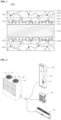
- FIG. 1 is a cross-sectional view showing a complex coating film in the present disclosure.
- a complex coating film 1000 comprises a metallic material 1100, a first coating layer 1200 formed on the metallic material 1100, and a second coating layer 1300 formed on the first coating layer 1200.
- the first coating layer 1200 comprises a first hydrophilic resin 1220, a metal compound 1240, a silane compound 1260, an amide-based cross linker 1280.
- the metal compound 1240 comprises the silane compound 1260 to improve a coupling force with the metallic material 1100. Since the silane compound 1260 exhibits a strong coupling force with metal, the metallic material 1100 that can be coated with the silane compound 1260 may comprise other metals including aluminum. Additionally, since the complex coating film comprises the first hydrophilic resin 1220 exhibiting hydrophilicity, the cross linker 1280 having an amide group is included to cure the first hydrophilic resin 1220 and to be coupled with a corrosion resisting agent.
- the second coating layer 1300 comprises a second hydrophilic resin 1320, a silica particle 1340 and a cross linker 1360.
- the cross linker 1360 is included to couple the second hydrophilic resin 1320 exhibiting hydrophilicity and the silica particle 1340.
- the second coating layer 1300 may be coupled to the first coating layer 1200 by the amide-based cross linker in the first coating layer 1200.
- the second coating layer 1300 may further comprise an additive such as an antibacterial agent to prevent a smell and a bacterial growth and the like.
- the first coating layer 1200 and the second coating layer 1300 may comprise a coating stabilizer or a coating preservative to store a coating composition for a long period of time.
- a degreasing process may be performed to ensure an adhesive force with the metallic material 1100, before a corrosion resistant and hydrophilic coating film in the present disclosure is formed.
- the complex coating film 1000 in the present disclosure may be applied to a fin of a heat exchanger, to allow heat exchange between air of a refrigerant pipe and air around the fin, and a plurality may be provided to enhance heat exchange.
- a fin and tube type heat exchanger of the present disclosure comprises: a distribution header distributing refrigerants
- FIG. 2 is a view showing the configuration of an air conditioner.
- a standing air conditioner or a ceiling-mounted air conditioner in the drawing is described an air conditioner, for example.
- the sort of the air conditioner is not restricted to the above-described ones, and a wall-mounted air conditioner or an integrated air conditioner in which an outdoor unit and an indoor unit do not separate can be included.
- the shape of the air conditioner is not restricted to the shape in the drawing.
- the air conditioner comprises an indoor unit 200 discharging conditioned air to an indoor space, and an outdoor unit 100 connecting to the indoor unit 200 and being disposed in an outdoor space.
- the outdoor unit 100 and the indoor unit 200 connect to a refrigerant pipe such that low-temperature air is discharged from the indoor unit 200 to an indoor space, based on the circulation of refrigerants.
- a plurality of indoor units 200 may be provided and connect to the outdoor unit 100.
- the air conditioner comprises a plurality of indoor units 200 and at least one outdoor unit 100 connecting to the plurality of indoor units 200.
- the plurality of indoor units 200 and the outdoor unit 100 connect to a refrigerant pipe, or connect to a communicable cable to transmit or receive a control instruction, based on a predetermined communication method.
- the indoor unit 200 comprises a discharge opening that discharges heat exchanged air.
- the discharge opening may be provided with an air direction adjuster that can open and close the discharge opening and control a direction of air discharged. Additionally, the indoor unit 200 may adjust an amount of air discharged from the discharge opening.
- a plurality of air inlets and a plurality of air outlets may have a plurality of vanes. The vane may open and close at least any one of the plurality of air inlets and the plurality of air outlets, and guide a flow direction of air.
- the indoor unit 200 may further comprise a display part that displays an operation state and setting information of the indoor unit 200, and an input part that is used to input setting data.
- the outdoor unit 100 may operate in a cooling mode or a heating mode, in response to the input instruction.
- the outdoor unit 100 may supply refrigerants to the plurality of indoor units 100, and the flow direction of air is guided along the discharge opening of the indoor unit 100 to adjust the environment of an indoor space.
- FIG. 3 is a perspective view showing a fin and tube type heat exchanger in the present disclosure
- FIG. 4 is a cross-sectional view showing a portion cut along I-I' in FIG. 3 .
- the fin and tube type heat exchanger 300 in one embodiment may comprise a distribution header 310 that distributes refrigerants flowing into the fin and tube type heat exchanger 300, at least one or more refrigerant pipes 320 that communicates with the distribution header 310, at least one or more fins 330 that are formed at one side of the refrigerant pipe 320, and a discharge header 350 that guides refrigerants discharged from the fin and tube type heat exchanger 300.
- the distribution header 310 may comprise a distribution pipe 312 that forms the outer shape of the distribution header 310, and an inflow part 314 that is formed in the end portion of the distribution pipe 312.
- the distribution pipe 312 may be a cylindrical pipe that has a hollow hole therein.
- the shape of the distribution pipe 312 is not restricted to a cylindrical shape.
- the distribution pipe 312 may be disposed horizontally with respect the ground surface. In other words, the distribution pipe 312 may be disposed perpendicularly with respect to the gravitational direction.
- the inflow part 314 may be defined as a portion to which the distribution pipe 312 connects.
- the inflow part 314 is a portion that guides refrigerants to the fin and tube type heat exchanger 300.
- the refrigerant pipe 320 guides refrigerants drawn from the distribution pipe 312 to the discharge header 350. Refrigerants passing through the refrigerant pipe 320 may exchange heat with air flowing in a direction across the refrigerant pipe 320.
- the refrigerant pipe 320 may be disposed horizontally with respect to the ground surface. In other words, the refrigerant pipe 320 may be disposed perpendicularly in the gravitational direction.
- the refrigerant pipe 320 may connect to the distribution pipe 312 in a direction perpendicular to the lengthwise direction of the distribution pipe 312.
- a plurality of refrigerant pipes 320 may be formed.
- the plurality of refrigerant pipes 320 may be disposed side by side on one surface. In other words, the plurality of refrigerant pipes 320 may be disposed to form one layer.
- the refrigerant pipe 320 may comprise a first refrigerant pipe, and a second refrigerant pipe provided at the lower side of the first refrigerant pipe.
- the first refrigerant pipe may draw refrigerants from the distribution header 310 and discharge the refrigerants to the second refrigerant pipe.
- the refrigerants drawn into the second refrigerant pipe may pass through the second refrigerant pipe and be guided to the discharge header 350.
- a redistribution header 340 may be provided between the first refrigerant pipe and the second refrigerant pipe and allow the first refrigerant pipe and the second refrigerant pipe to communicate.
- the redistribution header 340 may comprise a redistribution pipe 342, a first connection hole 344 being formed on the lateral surface of the redistribution pipe 342 and connecting to the first refrigerant pipe, and a second connection hole 346 being formed on the lateral surface of the redistribution pipe 342 and connecting to the second refrigerant pipe.
- the redistribution pipe 342 draws refrigerants drawn from the first refrigerant pipe, and discharges the drawn refrigerants to the second refrigerant pipe.
- the redistribution pipe 342 may have a hollow hole therein, and have a semicircular cross section. However, the shape of the redistribution pipe 342 is not restricted to a semicircular one.
- the redistribution pipe 342 may be disposed horizontally with respect to the ground surface. In other words, the redistribution pipe 342 may be disposed perpendicularly with respect to the gravitational direction.
- the redistribution pipe 342 and the distribution pipe 314 may be disposed in parallel. In other words, the distribution pipe 314 and the redistribution pipe 342 may be disposed in parallel with each other, and the refrigerant pipe 320 may be disposed between the distribution pipe 314 and the redistribution pipe 342.
- the redistribution pipe 342 may be disposed in a way that the redistribution pipe 342 is orthogonal to the refrigerant pipe 320.
- the refrigerant pipe 320 may be disposed in two layers in the present disclosure, but not restricted.
- the refrigerant pipe 320 may be disposed in three layers.
- a plurality of the redistribution headers 340 may be disposed in response to the number of layers of the refrigerant pipe 320. Detailed description in relation to this is omitted.
- the discharge header 350 may comprise a discharge pipe 352 forming the outer shape of the discharge header 350, and a discharge part 354 formed in the end portion of the discharge pipe 352.
- the fin 330 may be shaped into a planar heat conductor.
- the fin 330 may be disposed in a way that the fin 330 is perpendicular to the refrigerant pipe 320.
- the fin 330 may contact the refrigerant pipe 320, to improve heat transfer efficiency of the refrigerant pipe 320.
- the fin 330 may have a pipe insertion hole through which the refrigerant pipe 320 is inserted. In other words, the refrigerant pipe 320 may be disposed to penetrate the fin 330.
- a flow path of air passing through the fin and tube type heat exchanger 300 is described as follows.
- Air having passed through an indoor fan 221 may move to the fin and tube type heat exchanger 300. Specifically, the air having passed through the indoor fan 221 may move to a space formed among the plurality of fins 330. The air having moved to the space may exchange heat with refrigerants moving along the refrigerant pipe 320.
- frost may be formed on the outer surface of the plurality of fins 330. That is, refrigerants moving along the refrigerant pipe 320 and air being moved by the indoor fan 221 may have a different temperature. Additionally, a difference between the temperature of the refrigerants and the temperature of the air may increase further in the winter.
- the complex coating film 400 of the present disclosure may be formed at the fin 330.
- the coating film 400 may surround the outer surface of the fin 330 entirely. That is, the coating film 400 may also be formed in the edge portion of the fin 330.
- a coating film 400 formed in the edge portion of the fin 330 and a coating film 400 formed on one surface of the fin 330 may be respectively manufactured and then coupled, or may be manufactured integrally to surround the outer surface of the fin 330.
- the coating film 400 may prevent the fin 330 from directly contacting external air. Accordingly, frosting caused by frost that is made on the outer surface of the fin 330 may be minimized. That is, frosting on the outer surface of the fin 330 may be delayed.
- the coating film 400 may be applied to an outdoor unit. In the case where the coating film 400 is applied to an outdoor unit, drainage improves and frosting is delayed.
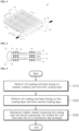
- FIG. 5 is a flowchart showing a manufacturing method of a fin and tube type heat exchanger in the present disclosure.
- the manufacturing method of a fin and tube type heat exchanger in the present disclosure comprises: performing roll coating and heat drying on a metallic material and forming a first coating layer (S10).
- the metallic material may be aluminum, copper, stainless steel, nickel and the like.
- the roll coating process involves applying coating for forming a coating layer to the upper end and the lower end of the metallic material by a roller, while the roller rotates, and the first coating layer is formed based on roll coating described above.
- the first coating layer is a layer having corrosion resistance and hydrophilicity, and as described above, comprises 10-40 wt% of a first hydrophilic resin, 1-20 wt% of a metal compound, 5-20 wt% of an amide-based cross linker, 1-15 wt% of a silane compound, and water as a remaining component.
- the drying process is preferably performed at 200-400 °C. In the case where temperature of the drying process is less than 200 °C, the first coating layer is not formed, and in the case where temperature of the drying process is greater than 400 °C, desired corrosion resistance and hydrophilicty may not be embodied.
- the manufacturing method of a fin and tube type heat exchanger in the present disclosure comprises performing roll coating and heat drying on the first coating layer and forming a second coating layer (S20).
- the second coating layer is a layer having hydrophilicity, and as described above, comprises 1-20 wt% of a second hydrophilic resin, 1-20 wt% of a silica particle, 0.01-5 wt% of a cross linker, 0.1-5 wt% of a solvent, and water as a remaining component.
- the second coating layer is formed on the metallic material where the first coating layer is formed, and formed based on the same roll coating and heat drying processes that are performed to form the first coating layer.
- the manufacturing method of a fin and tube type heat exchanger in the present disclosure comprises manufacturing the metallic material, on which the first coating layer and the second coating layer are formed, into a plurality of fins, inserting a tube into the plurality of fins, and forming a heat exchanger (S30).
- the metallic material where the first coating layer and the second coating layer are formed is punched and shaped into a fin, and a tube is inserted and welded into the fin, to manufacture a heat exchanger.
- FIG. 6 is a flow chart showing a manufacturing method of a microchannel type heat exchanger in the present disclosure.
- the manufacturing method of a microchannel type heat exchanger in the present disclosure comprises: dipping a microchannel type heat exchanger in a coating composition having corrosion resistance and hydrophilicity and forming a first coating layer (S100);
- the manufacturing method of a microchannel type heat exchanger in the present disclosure comprises immersing a microchannel type heat exchanger in a coating composition having corrosion resistance and hydrophilicity and forming a first coating layer (S100).
- a fin and/or a tube may be coated based on dipping, after the microchannel type heat exchanger is manufactured.
- the corrosion resistant and hydrophilic coating composition comprises 10-40 wt% of a first hydrophilic resin, 1-20 wt% of a metal compound, 5-20 wt% of an amide-based cross linker, 1-15 wt% of a silane compound, and water as a remaining component.
- the manufacturing method of a microchannel type heat exchanger in the present disclosure comprises immersing the microchannel type heat exchanger where the first coating layer is formed in a coating composition having hydrophilicty and forming a second coating layer (S200).
- the hydrophilic coating composition comprises 1-20 wt% of a second hydrophilic resin, 1-20 wt% of a silica particle, 0.01-5 wt% of a cross linker, 0.1-5 wt% of a solvent, and water as a remaining component.
- the manufacturing method of a microchannel type heat exchanger in the present disclosure comprises air blowing the lower end portion of the microchannel type heat exchanger (S300).
- the air blowing process is performed to remove the coating composition in the lower end portion of the microchannel type heat exchanger, and is preferably performed at pressure of 3-10 kgf/cm 2 .
- the coating composition in the lower end potion of the heat exchanger is not removed, and in the case where the air blowing process is performed at greater than 10 kgf/cm 2 , the coating composition is removed excessively. Accordingly, a target amount of coating is not coated, and the corrosion resistance and hydrophilicity of the heat exchanger deteriorate.
- the manufacturing method of a microchannel type heat exchanger in the present disclosure comprises drying the microchannel type heat exchanger (S400).
- the drying process is performed to deposit the coating composition, formed at the microchannel type heat exchanger, reliably as a film, and performed in a drying furnace, within a drying temperature range of 240 ⁇ 15 °C. Accordingly, a processing temperature range for forming a conventional coating film may be expanded by about 10 °C, and a mid range temperature may be decreased by about 10 °C to improve processability.
- the manufacturing method of a microchannel type heat exchanger in the present disclosure may further comprise degreasing and washing processes before the dipping process of the microchannel type heat exchanger.
- the degreasing and washing processes may be performed to remove oil components and contaminants existing on the surface of the heat exchanger, before the dipping of the microchannel type heat exchanger, ensuring improvement in an adhesive force of the heat exchanger and the coating film.
- a microchannel type heat exchanger of the present disclosure comprises: a plurality of flat tubes having a plurality of flow paths therein;
- microchannel type heat exchanger in the present disclosure is specifically described hereafter and enables heat exchange between air around the flat tube and air around the fin.
- a plurality of microchannel type heat exchangers may Be provided to improve heat exchange efficiency.
- An indoor unit and an outdoor unit of an air conditioner comprises: a cabinet assembly having an inlet into which indoor air is suctioned; and
- FIG. 7 is a perspective view showing a heat exchanger assembly in an indoor unit of an air conditioner in the present disclosure.
- a first microchannel type heat exchanger 501 and a second microchannel type heat exchanger 502 are separately manufacture, are stacked vertically and operate as one heat exchanger.
- one of the first microchannel type heat exchanger 501 and the second microchannel type heat exchanger 502 forms a parallel flow, and the other forms a counter flow.
- the microchannel type heat exchangers do not need to be replaced, even if the surface area of the inlet expands.
- a reliable coupling structure is provided through a supporter 510, and a pipe connection part is inserted into the supporter such that the pipe connection part is protected.
- Two heat exchangers having a height greater than a width are stacked for the heat exchange assembly 500, to deal with pressure imbalance between refrigerants at the upper side and refrigerants at the lower side.
- the first heat exchanger 501 and the second heat exchanger 502 may have the same structure.
- FIG. 8 is a cross-sectional view showing a microchannel type heat exchanger in the present disclosure.
- the structure of the first heat exchanger 501 is specifically described as an example.
- the first heat exchanger 501 comprises a first heat exchange part 530 exchanging heat with air, and a second heat exchange part 540 being stacked at the first heat exchange part 530 in a front-rear direction and exchanging heat with air.
- the first heat exchange part 530 and the second heat exchange part 540 are integrally manufactured in a furnace.
- the first heat exchange part 530 and the second heat exchange part 540 are microchannel type heat exchangers.
- the first heat exchange part 530 and the second heat exchange part 540 are made of aluminum.
- the first heat exchange part 530 comprises a plurality of flat tubes 550 having a plurality of flow paths therein, a fin 560 connecting the flat tubes 550 and transferring heat, a first lower header 570 being coupled to one side of the plurality of flat tubes 550, communicating with one side of the plurality of flat tubes 550 and allowing refrigerants to flow, a first upper header 580 being coupled to the other side of the plurality of flat tubes 550, communicating with the other side of the plurality of flat tubes 550 and allowing refrigerants to flow, and a baffle 590 being formed at least any one of the first lower header 270 or the first upper header 580 and partitioning the inside of the first lower header 570 to prevent refrigerants from flowing.
- the flat tube 550 has a flow path therein, which is elongated in the lengthwise direction of the flat tube 550 and in which refrigerants flow.
- the flat tube 550 is disposed perpendicularly, the plurality of flat tubes 550 is stacked in a left-right direction, and the flat tube 550 has a plurality of flow paths therein. Refrigerants flow along the lengthwise direction of the flat tube 550.
- the left side of the flat tube 550 is inserted into and communicates with the first lower header 570.
- the right side of the flat tube 550 is inserted into and communicates with the first upper header 580.
- the fin 560 bends and connects the two stacked flat tubes 550 to conduct heat.
- a low path of air passing through the microchannel type heat exchanger 501 is described as follows.
- Air having passed through an indoor fan may move to the heat exchanger 510. Specifically, the air having passed through the indoor fan may move to spaces formed among the plurality of fins 560. The air having moved to the spaces may exchange heat with refrigerants moving along the flat tubes 550.
- frost may be made on the outer surface of the plurality of fins 560. That is, refrigerants moving along the flat tubes 550 and air being moved by the indoor fan may have a different temperature. Additionally, a difference between the temperature of the refrigerants and the temperature of the air may increase further in the winter.
- a complex coating film of the present disclosure may be formed on the fin 560 and the flat tubes 550.
- the complex coating film may surround the outer surfaces of the fin 560 and the flat tubes 550 entirely.
- Aluminum metal was degreased at 60 °C for 30 seconds with an alkali solution, and then was washed at 50-70 °C and dried at 1 10 °C.
- the dried aluminum metal was annealed at 300 °C or less for 30 hours.
- An acrylic resin, a metal compound comprising Cr and Zr, a silane compound, an amide-based cross linker and water were mixed to manufacture a corrosion resistant and hydrophilic coating composition.
- the corrosion resistant and hydrophilic coating composition was coated on the surface of the aluminum metal, based on roll coating, and then dried at 230 °C, to form a first coating layer.
- a hydrophilic resin, a silica particle, a cross linker, a solvent and water were mixed to manufacture a hydrophilic coating composition.
- the hydrophilic coating composition was coated on the corrosion resistant and hydrophilic coating layer, based on roll coating, and then dried at 230 °C, to form a second coating layer.
- Table 1 hereafter shows the content of components included in the coating compositions of embodiments 1 to 6.
- First hydrophilic resin 15 20 25 30 35 40 Metal compound Chromium compound 2 4 5 6 8 10 Zirconium compound 1 3 5 7 9 10 Amide-based cross linker 5 8 11 13 15 20 Silane compound Epoxy group 1.5 2.5 3.5 4.5 5.5 7 Amino group 1.5 2.5 3.5 4.5 5.5 7 Amide-based cross linker 5 8 11 13 15 20 Water Remainin g portion Remainin g portion Remainin g portion Remainin g portion Remaining portion Remaining portion Hydrophil ic layer Second hydrophilic resin 2 4 7 12 15 20 Silica particle 1 5 10 13 17 20 Coupling cross linker 0.01 0.1 0.5 1 3 5 Solvent 0.1 0.5 1 2 3 5 Water Remainin g portion Remainin g
- the coating liquid was applied on an aluminum plate at 1 micron and heated for 30 seconds with hot air of 240 °C, to manufacture a coating layer.
- composition for hydrophilization was degreased with an aqueous solution where an alkali degreasing agent is dissolved at concentration of 2 %, applied to an aluminum plate treated with a cromate agent to form a dry film at 1 micron, and heated for 30 seconds with hot air of 240 °C, to manufacture a coating layer.
- FIG. 9(a) shows the exterior of an aluminum metal material after the formation of a complex coating film of the present disclosure on the surface of the aluminum metal material
- FIG. 9(b) shows an SEM photo of an aluminum metal material after the formation of a first coating layer of a complex coating film of the present disclosure, exhibiting corrosion resistance and hydrophilicity, on the aluminum metal material
- FIG. 9(c) shows an SEM photo of an aluminum metal material after the formation of a complex coating film of the present disclosure on the aluminum metal material.
- the exterior of the complex coating film of the present disclosure is in shades of gray color, and the complex coating film is formed uniformly.
- a porous structure of the complex coating film having corrosion resistance and hydrophilicity and an irregular structure of s silica particle of the second coating layer having hydrophilicity of the complex coating film are mixed. In the case where an irregular structure is formed on the surface and the roughness of the surface increases, hydrophilic performance is expected to improve.
- FIG. 10 is a photo showing a water contact angle before and after the formation of a complex coating film of the present disclosure on the surface of aluminum, and to measure the water contact angle, 10 ⁇ l of distilled water was dropped, and then a surface contact angle was measured.
- a coating amount was analyzed by calculating an amount of coating coated per sample area, based on a difference in weight before and after coating.
- ⁇ de notes a water spread diameter of 15 mm or greater
- ⁇ denotes a water spread diameter of 10-15 mm
- ⁇ de denotes a water spread diameter of 8-10 mm
- X denotes a water spread diameter of 8 mm or less.
- Table 2 shows that unlike comparative example 1, the original plate hydrophilicity, the initial hydrophilicity, the durable hydrophilicity and the long-lasting hydrophilicity of the complex coating film of the present disclosure are all excellent, as a result of measurement of hydrophilicity based on a coating amount.
- an acetic acid salt spray test (SWAAT, ASTM G85-A3) test simulating an aquatic environment that contains an acidic component was performed, a solution was comprised of 4.2 % of NaCl and 1 % of CH 3 COOH, the acidity of the solution was pH 2.8-3.0, and cycle conditions of a spray of the solution for 30 minutes (49 °C) and a wet atmosphere for one and a half hours (49 °C) were repeated.
- Example Comparative example 1 Comparative example 2 Complex coating film of the present disclosure Experimental period (time/hour) 360 360 168 288 360 432 528 676 Corrosion resistance (SWAAT 72hr) ⁇ ⁇ ⁇ ⁇ ⁇ ⁇ ⁇ ⁇ ⁇
- Table 3 shows that the R.N. of comparative example 1 is 8.0 or less (a rate of a corroded area of 0.10 % or greater and less than 0.25 %), and the R.N. of comparative example 2 is 7.0, while the R.N. of the complex coating film of the present disclosure is 9.8 or greater (a rate of a corroded area of less than 0.02 %) for 168-360 hours and is 8.0 or greater for 432-676 hours, in the case where a rating number is expressed based on a rate of a corroded area of the coating film.
- the coating film was accelerated through a wet/dry cycle test, and then the antibacterial performance of the coating film was tested.
- the coating film of comparative example 2 and the complex coating film of the present disclosure show the same results, i.e., an antibacterial property of 99.9 % or greater.
- the long-lasting acceleration-tested coating film has a higher antibacterial property than the coating film of comparative example 2.
- the number of remaining bacteria of the coating film of the present disclosure is 40 % less than that of the coating film of comparative example 2, ensuring a high anti bacterial property.
- distilled water was drained from a heat exchanger, and water remaining on the surface of the heat exchanger was weighed in the case where the distilled water was sprayed to the heat exchanger and then was left perpendicularly for a certain period of time.
- the complex coating film of the present disclosure, formed at the heat exchanger is more hydrophilic than that of comparative example 1 and comparative example 2. Accordingly, remaining water weighs less after the drainage test.
- a hydrophilic layer is additionally stacked on a corrosion resistant and hydrophilic coating layer, to improve hydrophilicity further.
Landscapes
- Engineering & Computer Science (AREA)
- Chemical & Material Sciences (AREA)
- Organic Chemistry (AREA)
- Life Sciences & Earth Sciences (AREA)
- Wood Science & Technology (AREA)
- Physics & Mathematics (AREA)
- Mechanical Engineering (AREA)
- General Engineering & Computer Science (AREA)
- Materials Engineering (AREA)
- Thermal Sciences (AREA)
- Chemical Kinetics & Catalysis (AREA)
- Medicinal Chemistry (AREA)
- Polymers & Plastics (AREA)
- Health & Medical Sciences (AREA)
- Nanotechnology (AREA)
- Inorganic Chemistry (AREA)
- Combustion & Propulsion (AREA)
- Geometry (AREA)
- Paints Or Removers (AREA)
- Laminated Bodies (AREA)
- Air Filters, Heat-Exchange Apparatuses, And Housings Of Air-Conditioning Units (AREA)
- Heat-Exchange Devices With Radiators And Conduit Assemblies (AREA)
Applications Claiming Priority (2)
| Application Number | Priority Date | Filing Date | Title |
|---|---|---|---|
| KR1020220014018A KR20230118208A (ko) | 2022-02-03 | 2022-02-03 | 복합 코팅막, 이를 포함하는 열교환기 및 열교환기의 제조방법 |
| PCT/KR2023/001568 WO2023149742A1 (ko) | 2022-02-03 | 2023-02-03 | 복합 코팅막, 이를 포함하는 열교환기 및 열교환기의 제조방법 |
Publications (3)
| Publication Number | Publication Date |
|---|---|
| EP4474064A1 true EP4474064A1 (de) | 2024-12-11 |
| EP4474064A4 EP4474064A4 (de) | 2025-05-28 |
| EP4474064B1 EP4474064B1 (de) | 2026-04-29 |
Family
ID=87552696
Family Applications (1)
| Application Number | Title | Priority Date | Filing Date |
|---|---|---|---|
| EP23749975.1A Active EP4474064B1 (de) | 2022-02-03 | 2023-02-03 | Rippenrohr- und mikrokanal-wärmeübertrager sowie deren herstellungsverfahren. |
Country Status (6)
| Country | Link |
|---|---|
| US (1) | US20250155207A1 (de) |
| EP (1) | EP4474064B1 (de) |
| JP (1) | JP2025505173A (de) |
| KR (1) | KR20230118208A (de) |
| CN (1) | CN118647466A (de) |
| WO (1) | WO2023149742A1 (de) |
Family Cites Families (8)
| Publication number | Priority date | Publication date | Assignee | Title |
|---|---|---|---|---|
| JP2001247822A (ja) * | 2000-03-06 | 2001-09-14 | Kansai Paint Co Ltd | 親水化処理用組成物及び親水化処理方法 |
| KR100469382B1 (ko) * | 2000-10-26 | 2005-01-31 | 한라공조주식회사 | 열교환기의 피막 형성방법 |
| KR101463050B1 (ko) | 2013-05-10 | 2014-11-18 | 한국과학기술원 | 초소수성 표면을 포함하는 재료 및 이의 제조 방법 |
| KR101677526B1 (ko) * | 2014-12-11 | 2016-11-21 | 주식회사 케미존 | 에어컨 열교환기용 일액형 내식, 친수 코팅제 및 이의 제조방법 |
| WO2019014685A1 (en) * | 2017-07-14 | 2019-01-17 | Inertech Ip Llc | SYSTEMS AND METHODS FOR MODULAR AIR COOLING AND DISPENSING |
| JP2019113250A (ja) * | 2017-12-22 | 2019-07-11 | 三菱アルミニウム株式会社 | 熱交換器用アルミニウムフィン材および熱交換器 |
| KR102580285B1 (ko) | 2018-07-10 | 2023-09-19 | 엘지전자 주식회사 | 열교환 시스템 |
| JP2021116993A (ja) * | 2020-01-29 | 2021-08-10 | 株式会社神戸製鋼所 | アルミニウムフィン材、熱交換器、空気調和機、および、アルミニウムフィン材の製造方法 |
-
2022
- 2022-02-03 KR KR1020220014018A patent/KR20230118208A/ko active Pending
-
2023
- 2023-02-03 CN CN202380020056.0A patent/CN118647466A/zh active Pending
- 2023-02-03 JP JP2024546169A patent/JP2025505173A/ja active Pending
- 2023-02-03 WO PCT/KR2023/001568 patent/WO2023149742A1/ko not_active Ceased
- 2023-02-03 EP EP23749975.1A patent/EP4474064B1/de active Active
- 2023-02-03 US US18/835,857 patent/US20250155207A1/en active Pending
Also Published As
| Publication number | Publication date |
|---|---|
| WO2023149742A1 (ko) | 2023-08-10 |
| KR20230118208A (ko) | 2023-08-11 |
| JP2025505173A (ja) | 2025-02-21 |
| CN118647466A (zh) | 2024-09-13 |
| EP4474064B1 (de) | 2026-04-29 |
| US20250155207A1 (en) | 2025-05-15 |
| EP4474064A4 (de) | 2025-05-28 |
Similar Documents
| Publication | Publication Date | Title |
|---|---|---|
| JPH0493597A (ja) | 撥水性コーティング用組成物及び撥水性コーティング用組成物を塗布した熱交換器 | |
| CN103703338B (zh) | 热交换器用预涂翅片材料及热交换器 | |
| KR940007204B1 (ko) | 열교환기 | |
| JP6596313B2 (ja) | プレコートフィン及び熱交換器 | |
| JP6151960B2 (ja) | 親水化表面処理金属材及び熱交換器 | |
| JPH08313191A (ja) | 熱交換器用アルミニウムフィン材 | |
| EP4474064A1 (de) | Verbundbeschichtungsfilm, wärmetauscher damit und verfahren zur herstellung eines wärmetauschers | |
| CN102443329B (zh) | 涂料组合物以及使用其的铝散热片材 | |
| US11168224B2 (en) | Heat exchanger coating | |
| JP2019073749A (ja) | 親水化表面処理アルミニウム含有金属材及び熱交換器 | |
| JP7601731B2 (ja) | アルミニウム製フィン材 | |
| JP2003201577A (ja) | 熱交換器フィン用アルミニウム又はアルミニウム合金材及び熱交換器用フィン | |
| JP3717205B2 (ja) | アルミニウム含有金属製熱交換器および製造方法 | |
| JP2507060B2 (ja) | アルミニウム製熱交換器及びその製造方法 | |
| JP2013210144A (ja) | アルミニウムフィン材 | |
| WO2015151909A1 (ja) | アルミニウム製フィン材 | |
| JP2584109B2 (ja) | 撥水性コーティング用塗料及びその塗料を塗布した熱交換器 | |
| JPH03244680A (ja) | 撥水性コーティング用組成物及び撥水性コーティング用組成物を用いた熱交換器 | |
| JP3274044B2 (ja) | 熱交換器用表面処理フィン材及びその製造方法 | |
| US20250035390A1 (en) | Coating composition, coating film, and micro channel type heat exchanger using the same | |
| JP4467264B2 (ja) | フィン用塗料組成物およびフィン材 | |
| JP2003336986A (ja) | 空調用熱交換器及びその製造方法 | |
| JPH05222339A (ja) | 撥水性コーティング用組成物及び撥水性コーティング用組成物を塗布した熱交換器 | |
| JPS61225044A (ja) | 熱交換器用アルミニウムフイン材 | |
| JPH03251693A (ja) | 撥水性コーティング用組成物及び撥水性コーティング用組成物を用いた熱交換器 |
Legal Events
| Date | Code | Title | Description |
|---|---|---|---|
| STAA | Information on the status of an ep patent application or granted ep patent |
Free format text: STATUS: THE INTERNATIONAL PUBLICATION HAS BEEN MADE |
|
| PUAI | Public reference made under article 153(3) epc to a published international application that has entered the european phase |
Free format text: ORIGINAL CODE: 0009012 |
|
| STAA | Information on the status of an ep patent application or granted ep patent |
Free format text: STATUS: REQUEST FOR EXAMINATION WAS MADE |
|
| 17P | Request for examination filed |
Effective date: 20240903 |
|
| AK | Designated contracting states |
Kind code of ref document: A1 Designated state(s): AL AT BE BG CH CY CZ DE DK EE ES FI FR GB GR HR HU IE IS IT LI LT LU LV MC ME MK MT NL NO PL PT RO RS SE SI SK SM TR |
|
| DAV | Request for validation of the european patent (deleted) | ||
| DAX | Request for extension of the european patent (deleted) | ||
| A4 | Supplementary search report drawn up and despatched |
Effective date: 20250428 |
|
| RIC1 | Information provided on ipc code assigned before grant |
Ipc: F28F 19/04 20060101ALI20250422BHEP Ipc: C08K 3/36 20060101ALI20250422BHEP Ipc: C08K 3/11 20180101ALI20250422BHEP Ipc: C08K 5/00 20060101ALI20250422BHEP Ipc: C09D 5/08 20060101ALI20250422BHEP Ipc: C09D 7/20 20180101ALI20250422BHEP Ipc: C09D 7/40 20180101ALI20250422BHEP Ipc: C09D 7/63 20180101ALI20250422BHEP Ipc: C09D 7/61 20180101ALI20250422BHEP Ipc: B05D 7/14 20060101AFI20250422BHEP |
|
| GRAP | Despatch of communication of intention to grant a patent |
Free format text: ORIGINAL CODE: EPIDOSNIGR1 |
|
| STAA | Information on the status of an ep patent application or granted ep patent |
Free format text: STATUS: GRANT OF PATENT IS INTENDED |
|
| INTG | Intention to grant announced |
Effective date: 20251222 |
|
| GRAS | Grant fee paid |
Free format text: ORIGINAL CODE: EPIDOSNIGR3 |
|
| GRAA | (expected) grant |
Free format text: ORIGINAL CODE: 0009210 |
|
| STAA | Information on the status of an ep patent application or granted ep patent |
Free format text: STATUS: THE PATENT HAS BEEN GRANTED |
|
| AK | Designated contracting states |
Kind code of ref document: B1 Designated state(s): AL AT BE BG CH CY CZ DE DK EE ES FI FR GB GR HR HU IE IS IT LI LT LU LV MC ME MK MT NL NO PL PT RO RS SE SI SK SM TR |
|
| REG | Reference to a national code |
Ref country code: CH Ref legal event code: F10 Free format text: ST27 STATUS EVENT CODE: U-0-0-F10-F00 (AS PROVIDED BY THE NATIONAL OFFICE) Effective date: 20260429 |