EP4470736B1 - Heftgerät - Google Patents
Heftgerät Download PDFInfo
- Publication number
- EP4470736B1 EP4470736B1 EP24179415.5A EP24179415A EP4470736B1 EP 4470736 B1 EP4470736 B1 EP 4470736B1 EP 24179415 A EP24179415 A EP 24179415A EP 4470736 B1 EP4470736 B1 EP 4470736B1
- Authority
- EP
- European Patent Office
- Prior art keywords
- staple
- shaping
- face plate
- shaping portion
- plate
- Prior art date
- Legal status (The legal status is an assumption and is not a legal conclusion. Google has not performed a legal analysis and makes no representation as to the accuracy of the status listed.)
- Active
Links
Images






Classifications
-
- B—PERFORMING OPERATIONS; TRANSPORTING
- B25—HAND TOOLS; PORTABLE POWER-DRIVEN TOOLS; MANIPULATORS
- B25C—HAND-HELD NAILING OR STAPLING TOOLS; MANUALLY OPERATED PORTABLE STAPLING TOOLS
- B25C5/00—Manually operated portable stapling tools; Hand-held power-operated stapling tools; Staple feeding devices therefor
-
- B—PERFORMING OPERATIONS; TRANSPORTING
- B27—WORKING OR PRESERVING WOOD OR SIMILAR MATERIAL; NAILING OR STAPLING MACHINES IN GENERAL
- B27F—DOVETAILED WORK; TENONS; SLOTTING MACHINES FOR WOOD OR SIMILAR MATERIAL; NAILING OR STAPLING MACHINES
- B27F7/00—Nailing or stapling; Nailed or stapled work
- B27F7/17—Stapling machines
- B27F7/26—Stapling machines without provision for bending the ends of the staples on to the work
- B27F7/28—Stapling machines without provision for bending the ends of the staples on to the work with means for forming the staples in the machine
-
- B—PERFORMING OPERATIONS; TRANSPORTING
- B27—WORKING OR PRESERVING WOOD OR SIMILAR MATERIAL; NAILING OR STAPLING MACHINES IN GENERAL
- B27F—DOVETAILED WORK; TENONS; SLOTTING MACHINES FOR WOOD OR SIMILAR MATERIAL; NAILING OR STAPLING MACHINES
- B27F7/00—Nailing or stapling; Nailed or stapled work
- B27F7/17—Stapling machines
- B27F7/38—Staple feeding devices
Definitions
- the present invention relates to a stapler that binds a bundle of sheets with a staple according to the preamble of claim 1.
- a stapler including a staple pusher (feeding portion) that presses connected staples (staple sheet) to which linear staples (linear staples) are bonded in parallel toward a front end plate (face plate), a forming plate that shapes the linear staple into a gate shape (U-shape), and a driver that moves up and down in conjunction with the forming plate and drives out the staple shaped by the forming plate (for example, see Patent Literature 1).
- both of a portion for shaping one side of a straight staple and a portion for shaping the other side of the straight staple in the forming plate are simultaneously retracted from the feeding path of the staple, and when the staple sheet is fed, the shaped staple is moved to a position at which the staple can be driven out by the driver.
- Patent Literature 1 JP H10 180710 A . This document discloses a stapler according to the preamble of claim 1.
- the present disclosure provides a stapler capable of reducing sound generated when a staple sheet comes into contact with a face plate.
- the present invention provides a stapler according to claim 1.
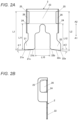
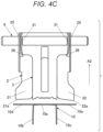
- the stapler comprises a forming plate configured to shape a leading staple of a staple sheet, which is formed by connecting a plurality of staples extending linearly in a direction perpendicular to an axial direction of the staples, into a U-shape, when viewed from a connection direction of the staples; a face plate provided at a position to be face the leading staple in the connection direction; and a feeding portion configured to, after the leading staple is shaped, feed the staple sheet in the connection direction, and configured to bring a linear staple positioned immediately behind the shaped staple into contact with the face plate.
Landscapes
- Engineering & Computer Science (AREA)
- Mechanical Engineering (AREA)
- Life Sciences & Earth Sciences (AREA)
- Forests & Forestry (AREA)
- Portable Nailing Machines And Staplers (AREA)
- Dovetailed Work, And Nailing Machines And Stapling Machines For Wood (AREA)
Claims (7)
- Hefter (1A), umfassend:eine Formplatte (2), die dazu eingerichtet ist, eine vordere Klammer eines Klammerbands, das durch Verbinden einer Vielzahl von Klammern, die sich linear in einer Richtung senkrecht zu einer axialen Richtung der Klammern erstrecken, ausgebildet ist, in eine U-Form zu bringen, wenn man aus einer Verbindungsrichtung der Klammern auf das Klammerband blickt;eine Stirnplatte (5), die an einer Position vorgesehen ist, die der vorderen Klammer in der Verbindungsrichtung gegenüberliegt; undeinen Zufuhrabschnitt (4), der dazu eingerichtet ist, nachdem die vordere Klammer geformt ist, das Klammerband in der Verbindungsrichtung zuzuführen, und der dazu eingerichtet ist, eine lineare Klammer, die unmittelbar hinter der geformten Klammer positioniert ist, in Kontakt mit der Stirnplatte zu bringen, wobeidie Formplatte (2) einen ersten Formabschnitt (21) umfasst, der dazu eingerichtet ist, einen Schenkelabschnitt der Klammer, der einen Teil der U-Form bildet, zu formen und einen zweiten Formabschnitt (22), der dazu eingerichtet ist, einen anderen Schenkelabschnitt davon zu formen, welcher einen anderen Teil der U-Form bildet,der erste Formabschnitt (21) dazu eingerichtet ist, an einer der Stirnplatte zugewandten Position einführbar und entfernbar zu sein, um den einen Schenkelabschnitt durch Biegen eines Teils der vorderen Klammer zu formen, indem er an der der Stirnplatte zugewandten Position eingeführt wird, und dazu eingerichtet ist, sich nach dem Formen aus der der Stirnplatte zugewandten Position zurückzuziehen, undder zweite Formabschnitt (22) dazu eingerichtet ist, an der der Stirnplatte (5) zugewandten Position einführbar und entfernbar zu sein, und den anderen Schenkelabschnitt durch Biegen eines anderen Teils der vorderen Klammer zu formen, indem er an der der Stirnplatte zugewandten Position eingeführt wird,dadurch gekennzeichnet, dass der zweite Formabschnitt (22) dazu eingerichtet ist, sich aus der der Stirnplatte (5) zugewandten Position zurückzuziehen, nachdem sich der erste Formabschnitt (21) nach der Formgebung aus der der Stirnplatte (5) zugewandten Position zurückgezogen hat.
- Hefter nach Anspruch 1, wobei
der zweite Formabschnitt (22) so ausgebildet ist, dass eine Länge desselben entlang einer Einführungs- und Entfernungsrichtung länger ist als eine Länge des ersten Formabschnitts (21) entlang der Einführungs- und Entfernungsrichtung. - Hefter nach Anspruch 1, wobei
die Formplatte (2) entlang der ihr zugewandten Stirnplatte (5) drehbar gelagert und so ausgelegt ist, dass sie gedreht werden kann, so dass der erste Formabschnitt (21) früher als der zweite Formabschnitt (22) zurückgezogen wird, nachdem die Schenkelabschnitte geformt sind. - Hefter nach Anspruch 2, wobeider erste Formabschnitt (21) und der zweite Formabschnitt (22) jeweils eine geneigte Fläche aufweisen, deren vorderer Endabschnitt in einer Einführrichtung nach außen geneigt ist, unddie geneigte Fläche des ersten Formabschnitts (21) einen Neigungswinkel aufweist, der sich von dem der geneigten Fläche des zweiten Formabschnitts (22) unterscheidet.
- Hefter nach Anspruch 4, wobei
eine hintere Endposition der geneigten Oberfläche des ersten Formabschnitts (21) in der Einführungs- und Entfernungsrichtung auf die gleiche oder im Wesentlichen die gleiche Position wie eine hintere Endposition der geneigten Oberfläche des zweiten Formabschnitts (22) in der Einführungs- und Entfernungsrichtung eingestellt ist. - Hefter nach Anspruch 1, ferner umfassendeine Mitnehmerplatte (3), die dazu eingerichtet ist, die Klammer durch Eindrücken eines Kronenabschnitts der durch die Formplatte (2) in die U-Form geformten Klammer auszutreiben, wobeidie Mitnehmerplatte (3) dazu eingerichtet ist, in einen Zuführweg der Klammer einführbar und aus diesem entfernbar zu sein, wenn der Kronenabschnitt hineingedrückt wird, und dazu eingerichtet ist, mit dem Kronenabschnitt in Kontakt zu kommen, indem sie in den Zuführweg eingeführt wird, um die Klammer auszutreiben, und dazu eingerichtet ist, sich aus dem Zuführweg zurückzuziehen, nachdem die Klammer ausgetrieben ist, undder erste Formabschnitt (21) und der zweite Formabschnitt (22) dazu eingerichtet sind, sich aus der Position, die der Stirnplatte (5) zugewandt ist, zurückzuziehen, nachdem sich die Mitnehmerplatte (3) aus dem Zuführweg zurückgezogen hat.
- Hefter nach Anspruch 1, wobei
die der Stirnplatte (5) zugewandte Position eine der Stirnplatte (5) zugewandte Position in einem Zuführweg der Klammer ist.
Applications Claiming Priority (1)
| Application Number | Priority Date | Filing Date | Title |
|---|---|---|---|
| JP2023090421A JP2024172599A (ja) | 2023-05-31 | 2023-05-31 | ステープラ |
Publications (2)
| Publication Number | Publication Date |
|---|---|
| EP4470736A1 EP4470736A1 (de) | 2024-12-04 |
| EP4470736B1 true EP4470736B1 (de) | 2025-07-09 |
Family
ID=91375059
Family Applications (1)
| Application Number | Title | Priority Date | Filing Date |
|---|---|---|---|
| EP24179415.5A Active EP4470736B1 (de) | 2023-05-31 | 2024-05-31 | Heftgerät |
Country Status (4)
| Country | Link |
|---|---|
| US (1) | US12377572B2 (de) |
| EP (1) | EP4470736B1 (de) |
| JP (1) | JP2024172599A (de) |
| CN (1) | CN119057737A (de) |
Family Cites Families (9)
| Publication number | Priority date | Publication date | Assignee | Title |
|---|---|---|---|---|
| US3524575A (en) * | 1967-03-30 | 1970-08-18 | Swingline Inc | Electric stapling machinne |
| US4366924A (en) * | 1980-11-03 | 1983-01-04 | Xerox Corporation | Stapler having an abutment for limiting stapler repenetration |
| US4623082A (en) * | 1985-05-14 | 1986-11-18 | Max Co. Ltd. | Electronic stapler |
| JPH0325931Y2 (de) * | 1986-10-31 | 1991-06-05 | ||
| JP3518217B2 (ja) | 1996-12-27 | 2004-04-12 | マックス株式会社 | 電動ステープラのステープル支持装置 |
| EP0838315B1 (de) | 1996-10-23 | 2004-02-25 | Max Co., Ltd. | Elektrischer Heftapparat |
| JP5359694B2 (ja) * | 2008-10-17 | 2013-12-04 | マックス株式会社 | ステープラのクリンチャ機構 |
| JP7003824B2 (ja) * | 2018-04-17 | 2022-02-04 | マックス株式会社 | カートリッジ |
| JP7251105B2 (ja) * | 2018-11-02 | 2023-04-04 | マックス株式会社 | ステープラ |
-
2023
- 2023-05-31 JP JP2023090421A patent/JP2024172599A/ja active Pending
-
2024
- 2024-05-30 US US18/678,882 patent/US12377572B2/en active Active
- 2024-05-31 EP EP24179415.5A patent/EP4470736B1/de active Active
- 2024-05-31 CN CN202410699915.XA patent/CN119057737A/zh active Pending
Also Published As
| Publication number | Publication date |
|---|---|
| JP2024172599A (ja) | 2024-12-12 |
| US20240399610A1 (en) | 2024-12-05 |
| US12377572B2 (en) | 2025-08-05 |
| CN119057737A (zh) | 2024-12-03 |
| EP4470736A1 (de) | 2024-12-04 |
Similar Documents
| Publication | Publication Date | Title |
|---|---|---|
| US6036074A (en) | Staple clinching mechanism in stapler | |
| KR100626980B1 (ko) | 전동 호치키스 | |
| US8251272B2 (en) | Stapler | |
| JP7810299B2 (ja) | ステープラ | |
| KR100709993B1 (ko) | 전동 호치키스 | |
| EP4470736A1 (de) | Heftgerät | |
| EP1769888B1 (de) | Klammervorrichtung und klammerpatrone | |
| EP3563999B1 (de) | Kartusche | |
| JP2003513812A (ja) | ステープルドライバ | |
| US20050098603A1 (en) | Stapler cartridge and stapler apparatus comprising the same | |
| CN100340374C (zh) | 订书机和卡盘 | |
| US12617061B2 (en) | Binding machine | |
| JP4465832B2 (ja) | 電動ステープラ | |
| CN118254131A (zh) | 订书机 | |
| JP4456441B2 (ja) | 連結ファスナー | |
| WO2026094948A1 (ja) | ステープラ | |
| JP2003136426A (ja) | ステープラー内のステープル形成機構 | |
| JP7856942B2 (ja) | 結束機 | |
| EP3147083B1 (de) | Heftgerät | |
| WO2005025810A1 (ja) | ステープラー | |
| JP5870715B2 (ja) | ステープラ | |
| JP2001191265A (ja) | 電動式ステープラー | |
| JP3692879B2 (ja) | 電動ホッチキス | |
| JPH0650140Y2 (ja) | 釘打機の釘供給ガイド装置 | |
| JP3444328B2 (ja) | 電動ホッチキスにおける綴り準備機構 |
Legal Events
| Date | Code | Title | Description |
|---|---|---|---|
| PUAI | Public reference made under article 153(3) epc to a published international application that has entered the european phase |
Free format text: ORIGINAL CODE: 0009012 |
|
| STAA | Information on the status of an ep patent application or granted ep patent |
Free format text: STATUS: THE APPLICATION HAS BEEN PUBLISHED |
|
| STAA | Information on the status of an ep patent application or granted ep patent |
Free format text: STATUS: REQUEST FOR EXAMINATION WAS MADE |
|
| AK | Designated contracting states |
Kind code of ref document: A1 Designated state(s): AL AT BE BG CH CY CZ DE DK EE ES FI FR GB GR HR HU IE IS IT LI LT LU LV MC ME MK MT NL NO PL PT RO RS SE SI SK SM TR |
|
| 17P | Request for examination filed |
Effective date: 20241122 |
|
| RBV | Designated contracting states (corrected) |
Designated state(s): AL AT BE BG CH CY CZ DE DK EE ES FI FR GB GR HR HU IE IS IT LI LT LU LV MC ME MK MT NL NO PL PT RO RS SE SI SK SM TR |
|
| GRAP | Despatch of communication of intention to grant a patent |
Free format text: ORIGINAL CODE: EPIDOSNIGR1 |
|
| STAA | Information on the status of an ep patent application or granted ep patent |
Free format text: STATUS: GRANT OF PATENT IS INTENDED |
|
| INTG | Intention to grant announced |
Effective date: 20250130 |
|
| GRAS | Grant fee paid |
Free format text: ORIGINAL CODE: EPIDOSNIGR3 |
|
| GRAA | (expected) grant |
Free format text: ORIGINAL CODE: 0009210 |
|
| STAA | Information on the status of an ep patent application or granted ep patent |
Free format text: STATUS: THE PATENT HAS BEEN GRANTED |
|
| AK | Designated contracting states |
Kind code of ref document: B1 Designated state(s): AL AT BE BG CH CY CZ DE DK EE ES FI FR GB GR HR HU IE IS IT LI LT LU LV MC ME MK MT NL NO PL PT RO RS SE SI SK SM TR |
|
| REG | Reference to a national code |
Ref country code: GB Ref legal event code: FG4D |
|
| REG | Reference to a national code |
Ref country code: CH Ref legal event code: EP |
|
| REG | Reference to a national code |
Ref country code: IE Ref legal event code: FG4D |
|
| REG | Reference to a national code |
Ref country code: DE Ref legal event code: R096 Ref document number: 602024000291 Country of ref document: DE |
|
| REG | Reference to a national code |
Ref country code: NL Ref legal event code: MP Effective date: 20250709 |
|
| PG25 | Lapsed in a contracting state [announced via postgrant information from national office to epo] |
Ref country code: PT Free format text: LAPSE BECAUSE OF FAILURE TO SUBMIT A TRANSLATION OF THE DESCRIPTION OR TO PAY THE FEE WITHIN THE PRESCRIBED TIME-LIMIT Effective date: 20251110 |
|
| PG25 | Lapsed in a contracting state [announced via postgrant information from national office to epo] |
Ref country code: NL Free format text: LAPSE BECAUSE OF FAILURE TO SUBMIT A TRANSLATION OF THE DESCRIPTION OR TO PAY THE FEE WITHIN THE PRESCRIBED TIME-LIMIT Effective date: 20250709 |
|
| REG | Reference to a national code |
Ref country code: AT Ref legal event code: MK05 Ref document number: 1811446 Country of ref document: AT Kind code of ref document: T Effective date: 20250709 |
|
| PG25 | Lapsed in a contracting state [announced via postgrant information from national office to epo] |
Ref country code: IS Free format text: LAPSE BECAUSE OF FAILURE TO SUBMIT A TRANSLATION OF THE DESCRIPTION OR TO PAY THE FEE WITHIN THE PRESCRIBED TIME-LIMIT Effective date: 20251109 |
|
| PG25 | Lapsed in a contracting state [announced via postgrant information from national office to epo] |
Ref country code: NO Free format text: LAPSE BECAUSE OF FAILURE TO SUBMIT A TRANSLATION OF THE DESCRIPTION OR TO PAY THE FEE WITHIN THE PRESCRIBED TIME-LIMIT Effective date: 20251009 |
|
| REG | Reference to a national code |
Ref country code: LT Ref legal event code: MG9D |
|
| PG25 | Lapsed in a contracting state [announced via postgrant information from national office to epo] |
Ref country code: AT Free format text: LAPSE BECAUSE OF FAILURE TO SUBMIT A TRANSLATION OF THE DESCRIPTION OR TO PAY THE FEE WITHIN THE PRESCRIBED TIME-LIMIT Effective date: 20250709 |
|
| PG25 | Lapsed in a contracting state [announced via postgrant information from national office to epo] |
Ref country code: FI Free format text: LAPSE BECAUSE OF FAILURE TO SUBMIT A TRANSLATION OF THE DESCRIPTION OR TO PAY THE FEE WITHIN THE PRESCRIBED TIME-LIMIT Effective date: 20250709 |
|
| PG25 | Lapsed in a contracting state [announced via postgrant information from national office to epo] |
Ref country code: HR Free format text: LAPSE BECAUSE OF FAILURE TO SUBMIT A TRANSLATION OF THE DESCRIPTION OR TO PAY THE FEE WITHIN THE PRESCRIBED TIME-LIMIT Effective date: 20250709 |
|
| PG25 | Lapsed in a contracting state [announced via postgrant information from national office to epo] |
Ref country code: GR Free format text: LAPSE BECAUSE OF FAILURE TO SUBMIT A TRANSLATION OF THE DESCRIPTION OR TO PAY THE FEE WITHIN THE PRESCRIBED TIME-LIMIT Effective date: 20251010 |
|
| PG25 | Lapsed in a contracting state [announced via postgrant information from national office to epo] |
Ref country code: SE Free format text: LAPSE BECAUSE OF FAILURE TO SUBMIT A TRANSLATION OF THE DESCRIPTION OR TO PAY THE FEE WITHIN THE PRESCRIBED TIME-LIMIT Effective date: 20250709 |
|
| PG25 | Lapsed in a contracting state [announced via postgrant information from national office to epo] |
Ref country code: LV Free format text: LAPSE BECAUSE OF FAILURE TO SUBMIT A TRANSLATION OF THE DESCRIPTION OR TO PAY THE FEE WITHIN THE PRESCRIBED TIME-LIMIT Effective date: 20250709 |
|
| PG25 | Lapsed in a contracting state [announced via postgrant information from national office to epo] |
Ref country code: BG Free format text: LAPSE BECAUSE OF FAILURE TO SUBMIT A TRANSLATION OF THE DESCRIPTION OR TO PAY THE FEE WITHIN THE PRESCRIBED TIME-LIMIT Effective date: 20250709 Ref country code: PL Free format text: LAPSE BECAUSE OF FAILURE TO SUBMIT A TRANSLATION OF THE DESCRIPTION OR TO PAY THE FEE WITHIN THE PRESCRIBED TIME-LIMIT Effective date: 20250709 |
|
| PG25 | Lapsed in a contracting state [announced via postgrant information from national office to epo] |
Ref country code: RS Free format text: LAPSE BECAUSE OF FAILURE TO SUBMIT A TRANSLATION OF THE DESCRIPTION OR TO PAY THE FEE WITHIN THE PRESCRIBED TIME-LIMIT Effective date: 20251009 |
|
| PG25 | Lapsed in a contracting state [announced via postgrant information from national office to epo] |
Ref country code: ES Free format text: LAPSE BECAUSE OF FAILURE TO SUBMIT A TRANSLATION OF THE DESCRIPTION OR TO PAY THE FEE WITHIN THE PRESCRIBED TIME-LIMIT Effective date: 20250709 |
|
| PG25 | Lapsed in a contracting state [announced via postgrant information from national office to epo] |
Ref country code: SM Free format text: LAPSE BECAUSE OF FAILURE TO SUBMIT A TRANSLATION OF THE DESCRIPTION OR TO PAY THE FEE WITHIN THE PRESCRIBED TIME-LIMIT Effective date: 20250709 |
|
| PG25 | Lapsed in a contracting state [announced via postgrant information from national office to epo] |
Ref country code: DK Free format text: LAPSE BECAUSE OF FAILURE TO SUBMIT A TRANSLATION OF THE DESCRIPTION OR TO PAY THE FEE WITHIN THE PRESCRIBED TIME-LIMIT Effective date: 20250709 |
|
| PG25 | Lapsed in a contracting state [announced via postgrant information from national office to epo] |
Ref country code: IT Free format text: LAPSE BECAUSE OF FAILURE TO SUBMIT A TRANSLATION OF THE DESCRIPTION OR TO PAY THE FEE WITHIN THE PRESCRIBED TIME-LIMIT Effective date: 20250709 |
|
| PG25 | Lapsed in a contracting state [announced via postgrant information from national office to epo] |
Ref country code: CZ Free format text: LAPSE BECAUSE OF FAILURE TO SUBMIT A TRANSLATION OF THE DESCRIPTION OR TO PAY THE FEE WITHIN THE PRESCRIBED TIME-LIMIT Effective date: 20250709 |
|
| PG25 | Lapsed in a contracting state [announced via postgrant information from national office to epo] |
Ref country code: SK Free format text: LAPSE BECAUSE OF FAILURE TO SUBMIT A TRANSLATION OF THE DESCRIPTION OR TO PAY THE FEE WITHIN THE PRESCRIBED TIME-LIMIT Effective date: 20250709 Ref country code: EE Free format text: LAPSE BECAUSE OF FAILURE TO SUBMIT A TRANSLATION OF THE DESCRIPTION OR TO PAY THE FEE WITHIN THE PRESCRIBED TIME-LIMIT Effective date: 20250709 |
|
| PLBE | No opposition filed within time limit |
Free format text: ORIGINAL CODE: 0009261 |
|
| STAA | Information on the status of an ep patent application or granted ep patent |
Free format text: STATUS: NO OPPOSITION FILED WITHIN TIME LIMIT |