EP4470734A1 - Greifvorrichtung zum greifen eines nahrungsmittels und fördervorrichtung mit einer solchen vorrichtung - Google Patents
Greifvorrichtung zum greifen eines nahrungsmittels und fördervorrichtung mit einer solchen vorrichtung Download PDFInfo
- Publication number
- EP4470734A1 EP4470734A1 EP24176860.5A EP24176860A EP4470734A1 EP 4470734 A1 EP4470734 A1 EP 4470734A1 EP 24176860 A EP24176860 A EP 24176860A EP 4470734 A1 EP4470734 A1 EP 4470734A1
- Authority
- EP
- European Patent Office
- Prior art keywords
- jaw element
- gripping device
- foodstuff
- jaw
- finger elements
- Prior art date
- Legal status (The legal status is an assumption and is not a legal conclusion. Google has not performed a legal analysis and makes no representation as to the accuracy of the status listed.)
- Granted
Links
Images


Classifications
-
- B—PERFORMING OPERATIONS; TRANSPORTING
- B25—HAND TOOLS; PORTABLE POWER-DRIVEN TOOLS; MANIPULATORS
- B25J—MANIPULATORS; CHAMBERS PROVIDED WITH MANIPULATION DEVICES
- B25J15/00—Gripping heads and other end effectors
- B25J15/0014—Gripping heads and other end effectors having fork, comb or plate shaped means for engaging the lower surface on a object to be transported
-
- B—PERFORMING OPERATIONS; TRANSPORTING
- B25—HAND TOOLS; PORTABLE POWER-DRIVEN TOOLS; MANIPULATORS
- B25J—MANIPULATORS; CHAMBERS PROVIDED WITH MANIPULATION DEVICES
- B25J11/00—Manipulators not otherwise provided for
- B25J11/0045—Manipulators used in the food industry
-
- B—PERFORMING OPERATIONS; TRANSPORTING
- B25—HAND TOOLS; PORTABLE POWER-DRIVEN TOOLS; MANIPULATORS
- B25J—MANIPULATORS; CHAMBERS PROVIDED WITH MANIPULATION DEVICES
- B25J15/00—Gripping heads and other end effectors
- B25J15/02—Gripping heads and other end effectors servo-actuated
- B25J15/0253—Gripping heads and other end effectors servo-actuated comprising parallel grippers
- B25J15/0293—Gripping heads and other end effectors servo-actuated comprising parallel grippers having fingers directly connected to actuator
-
- B—PERFORMING OPERATIONS; TRANSPORTING
- B65—CONVEYING; PACKING; STORING; HANDLING THIN OR FILAMENTARY MATERIAL
- B65G—TRANSPORT OR STORAGE DEVICES, e.g. CONVEYORS FOR LOADING OR TIPPING, SHOP CONVEYOR SYSTEMS OR PNEUMATIC TUBE CONVEYORS
- B65G47/00—Article or material-handling devices associated with conveyors; Methods employing such devices
- B65G47/74—Feeding, transfer, or discharging devices of particular kinds or types
- B65G47/90—Devices for picking-up and depositing articles or materials
Definitions
- the invention relates to a gripping device configured to grasp and contain a foodstuff, in particular a cured meat such as a piece of speck or a piece of bacon or a ham, in particular a raw ham.
- a gripping device configured to pick up a foodstuff from a support plane defined by conveying means on which the foodstuff is placed.
- the invention also relates to a conveying apparatus for conveying a foodstuff including such a gripping device and a conveying robot equipped with an arm connected to the gripping device to move the gripping device, and thus the foodstuff, along a conveying path.
- the gripping device is configured to pick up a foodstuff from the conveying means, for example from a conveyor belt, provided in a picking-up station and contain and support the foodstuff internally whilst the gripping device is conveyed, for example by the conveying apparatus according to the invention, to an unloading or release station in which the foodstuff is unloaded by the gripping device for example into a storage container.
- a cured meat processing line for processing for example, pieces of speck, pieces of bacon or hams, in particular raw hams, subjecting pieces of animal meat, in particular pig meat, to a plurality of processes is known, and it is known to arrange each piece of meat on a roller conveyor belt from which an operator takes one piece at a time to move the piece, still manually, to a storage container where the pieces of meat are collected before being subjected to successive processing or before being matured or before being marketed.
- the pieces of meat are divided into several storage containers on the basis of the weight of each piece of meat so that each storage container contains pieces of meat having a similar weight, i.e. the pieces of meat arranged in the same storage container differ from one another in weight by a set negligible amount.
- the operation of moving the pieces of meat from the conveying means to the storage containers can occur, for example, after the piece of meat has undergone salting or before undergoing salting, which can occur, for example, inside the storage containers.
- Hooking devices are known from the prior art for hooking the pieces of meat, each of which is arranged in particular to hook a raw ham to a maturing frame.
- hooking devices are shown by document GB 406793 A that describes a device for hanging meat comprising jaws provided with teeth and connected to arms hinged together in a connecting zone, and a sliding element carrying a wedge at the lower end of which a pair of tilted flanges is engaged.
- Each flange is integral with a respective arm so that the weight of the meat, by tending to drag the wedge to the connecting zone, closes the jaws with a force that increases with the weight of the meat.
- hooking devices do not allow the pieces of meat to be picked up from conveying means, but the pieces of meat have to be arranged manually by an operator between the jaws of these hooking devices.
- One object of the invention is to improve gripping devices for gripping a foodstuff of known type.
- Another object of the invention is to obtain a gripping device for gripping a foodstuff that enables a piece of meat to be grasped from conveying means.
- Still another object is to provide a conveying apparatus that enables a foodstuff to be gripped effectively from a conveying means in a picking-up station, the foodstuff to be conveyed along a set path and to be unloaded in an unloading station.
- the gripping device further includes at least one group of finger elements designed to support below the foodstuff and drive means configured to drive the at least one group of finger elements between a release/non-operating configuration and a support operating configuration.
- the group of finger elements includes a plurality of finger elements, each of which is configured to be able to be inserted between components of the conveying means, for example in a space defined between two adjacent rollers of a roller conveyor belt. In this manner, the finger elements can be positioned at a lower height than that of a support plane of the conveying means on which a foodstuff is placed, and, once the gripping device has been moved away from the support plane, i.e.
- the gripping device it is possible to pick up a foodstuff, in particular a cured meat, completely automatically and in a robotized manner from conveying means and contain the foodstuff therein effectively and without leaving any permanent mark on the outer surface of the foodstuffs. Further, owing to the conveying apparatus according to the invention equipped with the gripping device according to the invention it is possible to convey the foodstuff from a loading, or picking-up, station, to an unloading or release station without the foodstuff falling down.
- the gripping device is extremely compact and can be taken, when not in use, to a rest or non-operational position, with minimal overall dimensions in which the jaw elements are in a near position.
- a gripping device configured to grasp and contain a foodstuff, in particular a cured meat such as a piece of speck or a piece of bacon or a ham, the gripping device including:
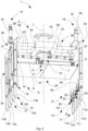
- a gripping device 1 for gripping a foodstuff in particular a cured meat such as a piece of speck or a piece of bacon or a ham, in particular a raw ham, according to the invention is shown that is configured to grasp and contain the foodstuff.
- the gripping device 1 is configured to pick up a foodstuff from a support plane defined in conveying means provided in a processing line for processing the foodstuff and for containing the foodstuff in particular during a movement of the gripping device 1 between a picking-up station provided in a zone of the conveying means in which the foodstuff is grasped by the gripping device 1 and a releasing/unloading station in which the foodstuff is unloaded by the gripping device 1 and, for example, is dropped by gravity inside a storage container.
- the gripping device 1 can be included in a conveying apparatus for conveying a foodstuff according to the invention that is configured to move the gripping device 1 between the picking-up station in which in use the gripping device 1 grasps the foodstuff that can then be contained inside a space of the gripping device 1 and the releasing/unloading station in which the gripping device 1 unloads the foodstuff which can then exit the gripping device 1, for example to be placed in the storage container.
- the gripping device 1 is in this configuration not suitable for containing the foodstuff.
- the pair of jaw elements includes a first jaw element 2a and a second jaw element 2b, in which the first jaw element 2a and the second jaw element 2b are reciprocally connected and, in use, are movable in relation to one another.
- first jaw element 2a and the second jaw element 2b When the first jaw element 2a and the second jaw element 2b are in the distanced position D, they can be in particular, further from a plane P ( Figure 5 ) of the gripping device 1, for example a plane of symmetry of the gripping device 1, with respect to when the first jaw element 2a and the second jaw element 2b are in the near position R.
- the first jaw element 2a can be fitted substantially specularly to the second jaw element 2b with respect to the plane P.
- the first jaw element 2a can include a first plate 3a provided with at least one first flat inner zone 4a intended to contact an outer part of the foodstuff, once picked up.
- This outer part is, in particular, an outer (side) surface portion of the foodstuff.
- the second jaw element 2b can include a second plate 3b provided with at least one second flat inner zone 4b designed to contact a further outer part of the foodstuff, once picked up.
- This further outer part is, in particular, a further outer (side) surface portion of the foodstuff.
- first flat inner zone 4a and the second flat inner zone 4b are arranged for contacting opposite sides of the foodstuff when the first jaw element 2a and the second jaw element 2b are in the near position R and the foodstuff has been picked up.
- the first plate 3a can be fitted substantially specularly to the second plate 3b with respect to the plane P.
- the gripping device 1 further includes distance adjusting means 5, operationally associated with the pair of jaw elements 2a, 2b and configured to adjust and maintain a distance L between the first jaw element 2a and the second jaw element 2b.
- the distance adjusting means 5 is connected stiffly to the first jaw element 2a and to the second jaw element 2b.
- the distance L is variable on the basis of the position in which the first jaw element 2a and the second jaw element 2b are arranged. In particular, the distance L will be greater in the distanced position D whereas it will be less in the near position R.
- the distance adjusting means 5 is operationally connected to the first jaw element 2a and/or to the second jaw element 2b for moving at least either the first jaw element 2a or the second jaw element 2b so as to take the first jaw element 2a and the second jaw element 2b to a set distance and maintain the first jaw element 2a and the second jaw element 2b at a set distance.
- the distance adjusting means 5 is configured to move at least either the first jaw element 2a or the second jaw element 2b for a substantially rectilinear stroke along an approach direction E to decrease the distance L or along a distancing direction F, opposite the approach direction E, to increase the distance L so as to take the first jaw element 2a and the second jaw element 2b to the set distance and to maintain the first jaw element 2a and the second jaw element 2b at the set distance.
- the distance adjusting means 5 in use, moves the first jaw element 2a and/or the second jaw element 2b along a substantially horizontal direction, in particular substantially perpendicular to the plane P, in particular substantially perpendicular to the vector associated with the force of gravity.
- both the first jaw element 2a and the second jaw element 2b are movable by the distance adjusting means 5 between the distanced position D and the near position R for a respective substantially rectilinear stroke along a respective approach direction E to decrease the distance L or along a respective distancing direction F, opposite the approach direction E, to increase the distance L so as to take the first jaw element 2a and the second jaw element 2 to the set distance and maintain the first jaw element 2a and the second jaw element 2b at the set distance.
- the respective approach directions E are opposite in direction, as the respective distancing directions F are.
- the distance adjusting means 5 are operationally associated both with the first jaw element 2a and with the second jaw element 2b and, in use, move both the first jaw element 2a and the second jaw element 2b for a respective substantially rectilinear stroke (i.e. neither the first jaw element 2a or the second jaw element 2b rotate during movement) along a respective approach direction E to decrease the distance L or along a respective distancing direction F, opposite said respective approach direction E, to increase the distance L so as to take the first jaw element 2a and the second jaw element 2b to the set distance and maintain the first jaw element 2a and the second jaw element 2b to the set distance.
- a respective substantially rectilinear stroke i.e. neither the first jaw element 2a or the second jaw element 2b rotate during movement
- a respective approach direction E to decrease the distance L or along a respective distancing direction F, opposite said respective approach direction E, to increase the distance L so as to take the first jaw element 2a and the second jaw element 2b to the set distance and maintain the first jaw
- the respective approach directions E are reciprocally opposite in direction, as the respective distancing directions F are reciprocally opposite in direction.
- the approach directions E are, in particular, substantially perpendicular to the plane P and in a direction facing the plane; the distancing directions F are, in particular, substantially perpendicular to the plane P but in a direction moving away from the plane P.
- the distance adjusting means 5 can include an actuating device 6 (for example shown in Figure 2 ) arranged to move away from one another or towards one another the first jaw element 2a and the second jaw element 2b.
- the actuating device 6 can be provided with a hollow body 7 including a head 8 operationally associated with, in particular fitted to, one of the jaw elements, for example the first jaw element 2a, and be provided with (at least) a stem 9, or cursor, or tip, an end portion 10 of which is operationally associated with, in particular is designed to contact, the other jaw element, for example the end portion is operationally associated with a second jaw element 2b.
- the stem 9 is slidable inside the hollow body 7 to move at least the other jaw element, in particular the second jaw element 2b, along the approach direction E or along the distancing direction F.
- the distance L between the first jaw element 2a and the second jaw element 2b is thus correlated with the protrusion of the stem 9 outside the hollow body 7.
- the head 8 is fitted to the first plate 3a of the first jaw element 2a and the end portion 10 of the stem 9 is so fitted as to contact an inner zone of the second plate 3b of the second jaw element 2b, i.e. a zone of the second plate 3b facing the inside of the gripping device 1.
- the actuating device 6 can be, in particular, a linear actuating device.
- the gripping device 1 can further include distance measuring means 66 (for example shown in Figure 1 ) arranged for measuring the distance L between the first jaw element 2a and the second jaw element 2b.
- the distance L can be measured constantly in particular whilst the first jaw element 2a and/or the second jaw element 2b are moved, so as to ensure that the first jaw element 2a and/or the second jaw element 2b are stopped with considerable precision when the distance L coincides with the set distance for a set work step.
- the distance measuring means 66 is connected stiffly to the first jaw element 2a and to the second jaw element 2b.
- the distance measuring means 66 When the distance measuring means 66 is not provided, it can be the operator who actuates and stops the distance adjusting means 5 so that the distance L substantially coincides with the set distance for a set work step.
- the distance measuring means 66 can include a linear movement transducing device 67, like, for example, a potentiometric rod, arranged to detect the distance L, in particular whilst the first jaw element 2a and the second jaw element 2b move reciprocally.
- a linear movement transducing device 67 is configured to convert the corresponding (linear) movement of the first jaw element 2a with respect to the second jaw element 2b into a variation of a physical parameter, for example an electrical resistance.
- the linear movement transducing device 67 generates an output signal that is proportionate to the measurement of a length, i.e. of the distance L.
- the linear movement transducing device 67 can be provided with a frame 76, which is in particular hollow, including a first end part 86 operationally associated with, in particular fitted to one of the jaw elements, for example to the first jaw element 2a, and with (at least) a cursor 96, an end portion of which is operationally associated with, in particular is designed to contact, the other jaw element, for example the second jaw element 2b.
- the cursor 96 is slidable with respect to the frame 76 to which it is connected, for example internally, proportionally to the movement of the first jaw element 2a and/or of the second jaw element 2b along the (respective) approach direction E or along the (respective) distancing direction F.
- the distance measuring means 66 in particular the linear movement transducing device 67, can be operationally associated with programmable electronic control means (for example a PLC) that can be provided, for example, in the conveying apparatus equipped with the gripping device 1.
- programmable electronic control means for example a PLC
- the linear movement transducing device 67 can be configured to send to the programmable electronic control means the signal that is proportionate to the measurement of the distance L that it detects.
- the programmable electronic control means is configured to control the gripping device 1.
- the set distance to which the first jaw element 2a and the second jaw element 2b must be taken in the closed configuration C is chosen following a foodstuff classification operation performed on the processing line of the foodstuff that determines the "cut", i.e. the weight and dimensions thereof.
- the selection operation is performed, in particular, by a vision system including at least one camera and at least one sensor device, like a weight sensor, by means of which the data concerning each foodstuff are detected, like the dimensions, in particular a maximum length, a maximum width and a maximum thickness, and a weight of the foodstuff.
- a vision system including at least one camera and at least one sensor device, like a weight sensor, by means of which the data concerning each foodstuff are detected, like the dimensions, in particular a maximum length, a maximum width and a maximum thickness, and a weight of the foodstuff.
- the operation of classifying the foodstuffs is performed upstream of a work zone in which the gripping device 1 grasps the foodstuffs.
- the programmable electronic control means receives the signal indicating the distance L that the distance measuring means 66 detects continuously in real time during movement of the first jaw element 2a and/or of the second jaw element 2b between the near position R and the distanced position D.
- the programmable electronic control means (or the operator if the latter is not provided) commands the distance adjusting means 5 to interrupt movement of the first jaw element 2a and/or of the second jaw element 2b (i.e. it interrupts sliding of the stem 9 when the actuating device 6 is provided).
- the distance adjusting means 5, in particular the actuating device 6, and the distance measuring means 66, in particular the linear position transducing device 67, are respectively connected to the programmable electronic control means by means of connecting means of known type that can include, for example, a wireless connection, one or more transceiver devices, or other components suitable for establishing a connection, for example a wireless connection, between the distance adjusting means 5, in particular the actuating device 6, the distance measuring means 66, in particular the linear movement transducing device 67, and the programmable electronic control means.
- the previously mentioned connection enables the programmable electronic control means to send data to and/or receive data from the distance adjusting means 5 and/or distance measuring means 66, these transceiver devices or other components being of known type and therefore not being disclosed here in a detailed manner.
- the data that can be exchanged between the programmable electronic control means and the distance measuring means 66 are, in particular, set values corresponding to the distance L that the distance adjusting means 5, in particular the actuating device 6, has to impose between the first jaw element 2a and the second jaw element 2b, in the various work steps, for example to be able to grasp the foodstuff, and set values relating to a height to which the gripping device 1 is to be taken in the various work steps, for example to be able to pick up the foodstuff from the support plane of the conveying means, or to be moved from the picking-up station to the releasing station.
- the data can include the measurement (in particular the signal proportionate to such a measurement) of the distance L detected by the distance measuring means 66.
- the values relating to the set distance are based on the data relating to each foodstuff detected by the vision system following the classification operation.
- the values relating to the set distance to which the first jaw element 2a and the second jaw element 2b must be taken, in the various work steps, for example in the near position R, are determined, for example, by the operator by a recipe set on the programmable electronic control means by the operator and are based on the dimensions of the foodstuff that the gripping device 1 has to pick up and subsequently convey.
- the distance adjusting means 5, in particular the actuating device 6 then has the function of determining a movement for a substantially rectilinear stroke of the first jaw element 2a (and/or of the second jaw element 2b) along the (respective) approach direction E that is useful for not squashing the foodstuff too much.
- the movement of the first jaw element 2a and/or of the second jaw element 2b caused by the distance adjusting means 5 is such that the end distance L between the first jaw element 2a and the second jaw element 2b is the same as the set distance in a given work step.
- the gripping device 1 further includes at least one group of finger elements, for example the group of finger elements 11, intended to support the foodstuff below.
- the group of finger elements 11 includes a plurality of finger elements 11a,...11n movable between a release or non-operational configuration N, (shown for example in Figure 1 ) in which they do not interact with the foodstuff and a support operating configuration O (shown for example in Figure 3 ) in which they support the foodstuff below.
- Each of the finger elements 11a,...11n of the group of finger elements 11 is arranged near an end zone 12a of the first jaw element 2a.
- the finger elements 11a,...11n can be arranged equidistant.
- the gripping device 1 can further include a further group of finger elements 13 that is shaped, in particular, substantially like the group of finger elements 11.
- the further group of finger elements 13 includes a plurality of further finger elements 13a, ..., 13n arranged substantially specularly to the finger elements 11a, ..., 11n and movable, in use, in coordination (for example by the programmable electronic control means) with the latter to promote supporting the foodstuff below in synergy with the finger elements 11a, ..., 11n.
- the further finger elements 13a,...13n can be arranged equidistant.
- Each of the further finger elements 13a,...13n of the further group of finger elements 13 is arranged near a further end zone 12b of the second jaw element 2b.
- FIG. 1 An embodiment of a gripping device 1 is shown in the Figures in which both the group of finger elements 11 and the further group of finger elements 13 are present.
- the gripping device 1 includes five finger elements 11a, ...11e and five further finger elements 13a, ...13e.
- the number of finger elements 11a, ... 11e and the number of further finger elements 13a, ... 13e can differ.
- one of these groups of finger elements 11, 13 can be missing.
- the dimensions of the finger elements 11a, ..., 11n and/or of the further finger elements 13a, ..., 13n, in particular a length thereof, are so chosen as to be able to support the foodstuff both during gripping of the foodstuff from the support plane by the gripping device 1 and during the movement of the gripping device 1 between the picking-up station and the releasing station.
- the gripping device 1 further includes drive means 14 operationally associated with at least one group of finger elements, for example the group of finger elements 11, and configured to drive the finger elements 11a, ..., 11n (and/or the further finger elements 13a,...13n when provided) between the release configuration N and the support operating configuration O.
- drive means 14 operationally associated with at least one group of finger elements, for example the group of finger elements 11, and configured to drive the finger elements 11a, ..., 11n (and/or the further finger elements 13a,...13n when provided) between the release configuration N and the support operating configuration O.
- the drive means 14 is further configured to maintain the group of finger elements 11 and/or the further group of finger elements 13 in the release configuration R or in the support operating configuration O.
- the finger elements 11a, ...11n and/or the further finger elements 13a, ... 13n extend, in particular, along a substantially vertical direction V, in particular downwards, substantially parallel to the vector associated with the force of gravity.
- the surface of the support plane of the conveying means on which the foodstuff is arranged is, in particular, substantially perpendicular to the vertical direction V.
- the finger elements 11a, ... 11n and/or the further finger elements 13a, ... 13n extend prevalently, in particular, along a direction that is substantially perpendicular to the vertical direction V.
- the drive means 14 is configured to rotate the finger elements 11a, ...11n and/or the further finger elements 13a, 13n between the release configuration N and the support operating configuration O.
- the pair of jaw elements 2a, 2b and at least one group of finger elements are configured to cooperate in order to grasp and contain in the gripping device 1 the foodstuff when the pair of jaw elements 2a, 2b is in the near position R and at least one group of finger elements is in the support operating configuration O, or in order to unload from the gripping device 1 the foodstuff when the pair of jaw elements 2a, 2b is in the distanced position D and at least one group of finger elements or each group of finger elements is in the release configuration N.
- the gripping device 1 can be defined in the open configuration A when the pair of jaw elements 2a, 2b is in the distanced position D and the group of finger elements 11 and/or the further group of finger elements 13, when the latter is present, is in the release configuration N.
- the open configuration A is adopted by the gripping device 1, in particular, before picking up the foodstuff or when the foodstuff has to be unloaded by the gripping device 1 or after the foodstuff has been unloaded by the gripping device 1.
- the gripping device 1 on the other hand, can be defined in the closed configuration C when the pair of jaw elements 2a, 2b is in the near position R and the group of finger elements 11 and/or the further group of finger elements 13, when the latter is present, is in the support operating configuration O.
- the closed configuration C is adopted by the gripping device 1, in particular, to pick up the foodstuff and when the foodstuff has to be contained inside the gripping device 1 to be able to be conveyed, for example from the picking-up station to the releasing station.
- the finger elements 11a, ...11n and the further finger elements 13a, ...13n each include a respective first end 15 shaped and acting as a cam that is rotatably connected to the drive means 14.
- Each first end 15 includes a first zone 17 and a second zone 20 to which the drive means 14 is rotatably connected.
- the finger elements 11a, ...11n and the further finger elements 13a, ... 13n each include a respective second end 65, opposite a respective first end 15, that can be tooth shaped.
- the drive means 14 includes at least one rotation rod 16 connected to the first zone 17 of the first end 15 of the finger elements 11a, ... 11n.
- the first end 15 of each finger element 11a, ... 11n and of each further finger element 13a, ...13n is, in use, rotatable around the respective rotation rod 16, 26 when the finger elements 11a, ... 11n and the further finger elements 13a, ...13n, when present, are moved between the release configuration N and the support operating configuration O.
- the rotation rod 16 and the other rotation rod 26 act as a fulcrum for rotating respectively the finger elements 11a, ... 11n and the further finger elements 13a, ... 13n, when the latter are present.
- the drive means 14 further includes at least one drive element 18 and a first pulling/pushing rod 19 connected to the second zone 20 of each first end 15 of the finger elements 11a, ...11n.
- the (at least one) drive element 18 is configured to pull or push the first pulling/pushing rod 19 and the other first pulling/pushing rod 29 (when the latter is present) so as to cause a rotation of the finger elements 11a, 11n and of the further finger elements 13a, 13n, when the latter are present, respectively around the rotation rod 16 and the other rotation rod 26, alternatively in one rotation direction (for pulling) or in an opposite direction (for pushing).
- the drive element 18 can be a pneumatic actuator, in particular a pneumatic cylinder.
- the gripping device 1 can include only one drive element 18 that drives both the groups of finger elements 11, 13 or a plurality of drive elements 18, for example a drive element 18 for each group of finger elements 11, 13 as in the embodiment illustrated in the Figures.
- the drive element 18, or the drive elements 18 are, in particular, fitted to the first plate 3a and/or to the second plate 3b, for example at a folded portion 48 of the first plate 3a and/or of the second plate 3b.
- the finger elements 11a,...11n and the further finger elements 13a,...13n can be connected to the rotation rod 16 or to the other rotation rod 26 and to the first pulling/pushing rod 19 or to the other first pulling/pushing rod 29 by means, respectively, of a first hole 21 obtained in the first zone 17 of each finger element 11a,...11n and of each further finger element 13a,...13n, when present, and of a second hole 22 obtained in the second zone 20 of each finger element 11a,...11n and of each further finger element 13a,...13n, when present.
- the rotation rod 16 and the other rotation rod 26, when the latter is present, and the first pulling/pushing rod 19 and the other first pulling/pushing rod 29, when the latter is present, are inserted, respectively, into the first holes 21 or into the second holes 22.
- the coupling between the first holes 21 and the second holes 22 and, respectively, the finger elements 11a,...11n and the further finger elements 13a,...13n, occurs by minimum clearance that at the same time enables the finger elements 11a,...11n and the further finger elements 13a,...13n to rotate around the respective rotation rods 16, 26 and pulling/pushing rods 19, 29, without the finger elements 11a,...11n and the further finger elements 13a,...13n, being able to slide along the rods.
- the rotation rod 16 and the other rotation rod 26, when the latter is present, can be connected stiffly respectively to the first plate 3a and to the second plate 3b by means of a respective connecting element 23, for example including a connecting rod.
- the drive means 14 further includes at least one system of rods 24 arranged to connect the drive element 18 to the first pulling/pushing rod 19 and to consequently drive the first pulling/pushing rod 19 upwards or downwards according to the pulling or pushing action set by the drive element 18.
- the gripping device 1 in fact further includes another system of rods 34, which is identical to the system of rods 24 and is arranged to connect the other drive element 18 to the other first pulling/pushing rod 29.
- the system of rods 24 can include a first group of rods 25 provided with a plurality of rods 27, such rods 27 each extending with a substantially vertically prevalent dimension and being alongside each other.
- Each rod 27 includes a first end zone 28 connected to the first pulling/pushing rod 19 and a second end zone 30, opposite the first end zone 28, connected to a further pulling/pushing rod 39.
- the further pulling/pushing rod 39 is connected to the drive element 18 in particular by means of a fork element 31 provided in the gripping device 1.
- the system of rods 24 can further include a second group of rods 32 provided with a plurality of further rods 33, the further rods 33 each extending with a substantially vertically prevalent dimension and being alongside each other.
- Each further rod 33 includes an end 35 connected to the further pulling/pushing rod 39 and a further end 36, opposite the end 35, connected to a still further pulling/pushing rod 49. If also the second group of rods 32 is present, the fork element 31 can be connected to the still further pulling/pushing rod 49.
- the first plate 3a and/or the second plate 3b can include each, a pair of flaps 37, the flaps 37 of each pair of flaps being arranged facing one another.
- Each flap 37 can extend along an edge of the first plate 3a and/or of the second plate 3b.
- Each flap 37 can extend along a height of the first plate 3a and/or of the second plate 3b, in particular along the entire height of the first plate 3a and/or of the second plate 3b.
- Each flap 37 can be made by folding a portion of sheet metal that is the precursor of the first plate 3a or of the second plate 3b.
- At least one opening 38 is obtained in each flap 37.
- the openings 38 of a pair of flaps 37 are obtained, and the flaps 37 are so fitted that in the openings 38 two portions of the further pulling/pushing rod 39 can be housed slidingly.
- a further opening 40 can also be obtained in each flap 37.
- the further openings 40 of a pair of flaps 37 are obtained, and the flaps 37 are fitted, so that in the further openings 40 two portions of the still further pulling/pushing rod 49 can be slidingly housed.
- Each opening 38 and/or each further opening 40 can have a substantially L-shaped plan view.
- the rotation rod 16 and the other rotation rod 26, when the latter is present, are rotatably connected, in particular at the respective ends, to a pair of facing flaps 37.
- the further pulling/pushing rod 39 and the still further pulling/pushing rod 49 slide upwards under the pulling action of the drive means 14 respectively inside the openings 38 and the further openings 40, whilst when the drive means 14 drives the finger elements 11a,...11n and the possible further finger elements 13a, ... 13n from the support operating configuration O to the release configuration N, the further pulling/pushing rod 39 and the still further pulling/pushing rod 49 slide downwards under the thrust action of the drive means 14, i.e. along a direction substantially parallel to the vertical direction V, respectively inside the openings 38 and the further openings 40.
- the further pulling/pushing rod 39 and the still further pulling/pushing rod 49 are arranged, in particular, resting on a portion of the openings 38 and of the further openings 40, respectively.
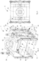
- the gripping device 1 can further include a centring unit 41 configured to ensure that the stroke travelled by the first jaw element 2a and the stroke travelled by the second jaw element 2b are substantially the same.
- the foodstuff when it is picked up from a support plane, can be grasped by the first jaw element 2a and by the second jaw element 2b arranged in the near position R at the set distance on the basis of a dimension of the foodstuff to be picked up, for example a width, without entailing sliding of the foodstuff with respect to the first jaw element 2a or to the second jaw element 2b.
- a dimension of the foodstuff to be picked up for example a width
- the centring unit 41 can include, in one embodiment of a gripping device 1 like the one shown in the Figures, a rotating table 42 that is rotatable around a substantially vertical rotation axis T, and a pair of tie rods 43, each tie rod 43 being connected rotatably on one side to the rotating table 42, in particular to a face 44 of the rotating table 42, and on the other side to a respective jaw element 2a, 2b, in particular to the first plate 3a or to the second plate 3b.
- the rotating table 42 is rotated when the first jaw element 2a and the second jaw element 2b are driven to move along the respective stroke by the distance adjusting means 5.
- the tie rods 43 are fitted to the face 44 of the rotating table 42 so as to enable a movement of the first jaw element 2a and of the second jaw element 2b by an equal amount.
- the rotating table 42 can have a disc shape.
- the rotating table 42 can include a further face 54, opposite the face 44, by which the rotating table 42 is connected to a support block 55, in turn connected to the first jaw element 2a and to the second jaw element 2b by sliding support means 56.
- the rotating table 42 rotates around the rotation axis T in a rotation direction, whereas when the first jaw element 2a and the second jaw element 2b are brought near one another along the approach directions E, the rotating table 42 rotates around the rotation axis T in an opposite rotation direction, because of the fact that the tie rods 43 are dragged to move as a result of the movement of the first jaw element 2a and of the second jaw element 2b.
- the sliding support means 56 and the support block 55 are configured to connect the first jaw element 2a to the second jaw element 2b.
- the sliding support means 56 and the support block 55 are configured to slidingly support and guide the first jaw element 2a and the second jaw element 2b when they are moved along a substantially horizontal direction (to the first jaw element 2a and/or to the second jaw element 2b), i.e. when they are moved along the approach direction E or along the distancing direction F between the distanced position D and the near position R.
- the sliding support means 56 includes a first support rod 57 connected in a fixed manner on one side, in particular at one end, to the first jaw element 2a, in particular to an inner part of the first plate 3a, and on the other side being slidingly received inside the support block 55.
- the sliding support means 56 further includes a second support rod 58 connected in a fixed manner on one side, in particular at one end, to the second jaw element 2b, in particular to an inner part of the second plate 3b, and on the other side being slidingly received inside the support block 55.
- the sliding support means 56 can further include a further first support rod 59, which is identical to the first support rod 57.
- the sliding support means 56 can further include a further second support rod 60, which is identical to the second support rod 58.
- the support block 55 includes a body 61 in which a plurality of through holes 62 is obtained each of which is designed to slidingly receive a portion of the first support rod 57, of the second support rod 58, of the further first support rod 59 and of the further second support rod 60, where these rods are provided.
- still further support rods can be provided that are identical to those disclosed previously.
- first support rod 57, the second support rod 58, the further first support rod 59, the further second support rod 60 and the still further support rods when present, slide inside the respective through holes 62 depending on the set distance to which the first jaw element 2a and the second jaw element 2b are taken by the distance adjusting means 5.
- the centring unit 41 can include a ring gear, in particular a cogwheel that is rotatable around a substantially vertical rotation axis, and a pair of linear gears, in particular a pair of racks.
- Each linear gear is provided with a plurality of teeth arranged for engaging a plurality of further teeth provided in the ring gear.
- Each linear gear is coupled on one side with the ring gear and on the other side is connected to a respective jaw element 2a, 2b.
- the ring gear is rotated when the first jaw element 2a and the second jaw element 2b are moved for the respective stroke by the distance adjusting means 5.
- the linear gears are coupled with the ring gear so as to enable a movement of the first jaw element 2a and of the second jaw element 2b for an equal stroke.
- the gripping device 1 can further include a cover device 45 arranged to cover from above the foodstuff when the gripping device 1 has grasped the foodstuff, i.e. when the first jaw element 2a and the second jaw element 2b are in the near position R.
- the cover device 45 includes at least one first cover plate 46 fitted to either the first plate 3a or the second plate 3b, for example the first plate 3a.
- the first cover plate 46 can be fitted so as to be substantially perpendicular to the vertical direction V when the gripping device 1 is in the closed configuration C.
- the gripping device 1 further includes a second cover plate 47 fitted to one of the first plate 3a or second plate 3b to which first cover plate 46 is not fitted, for example to the second plate 3b.
- the second cover plate 47 can be fitted so as to be substantially perpendicular to the vertical direction V when the gripping device 1 is in the closed configuration C.
- the second cover plate 47 and first cover plate 46 can be fitted on top of one another and so as to be substantially parallel to one another.
- the conveying apparatus for conveying the foodstuff in addition to including at least one gripping device 1 and the programmable electronic control means, can further include a conveying robot for conveying the foodstuff.
- the robot includes a robotic arm, in particular an anthropomorphic robotic arm, connectable to the gripping device 1 to be able to grasp and convey the latter along a path, for example between the picking-up station and the releasing station.
- the robotic arm can be configured to grasp a hooking element 50 provided in the gripping device 1.
- the hooking element 50 can include a circular plate 51 fitted to the support block 55, for example using a support element 52, for example shaped like a column.
- the circular plate 51 has a circumferential portion 53 that protrudes radially beyond the support element 52.
- the circumferential portion 53 can be designed to be grasped by the robotic arm, or to be fitted to the robotic arm.
- the height values which, in use, the gripping device 1 has to attain are entered by the operator into the programmable electronic control means, which transforms the height values into coordinates that the programmable electronic control means sends, in use, to the conveying robot.
- the programmable electronic control means is configured to coordinate a movement of the pair of jaw elements 2a, 2b and of at least one group of finger elements, for example the group of finger elements 11, in particular of the pair of groups of finger elements 11, 13 in accordance with a movement of the robotic arm of the conveying robot between the picking-up station in which the gripping device 1 grasps the foodstuff and the releasing station in which the gripping device 1 releases the foodstuff.
- the values relating to the heights to which the gripping device 1 has to be taken by the conveying apparatus in the work steps are preliminarily first entered into the programmable electronic control means, in particular by the operator, in particular in the picking-up station, in the releasing station and along the path between the two stations.
- Such height values are based, in particular, on the height with respect to the ground on which the support plane is arranged, and on a height of the storage container inside which the foodstuff has to be unloaded, in order to avoid collisions therewith.
- the gripping device 1 that is in the open configuration A, is taken by the conveying apparatus to a height that is suitable with respect to the support plane.
- a base of the foodstuff is substantially at the same height as the end zone 12a and as the further end zone 12b respectively of the first jaw element 2a and as the second jaw element 2b.
- the first jaw element 2a and the second jaw element 2b are taken by the distance adjusting means 5 in the near position R to the set distance, for example by moving only one jaw element 2a; 2b along the approach direction E with respect to the other jaw element 2b; 2a or both the jaw elements 2a, 2b along the respective approach directions E.
- the programmable electronic control means (or the operator if the latter is not provided) commands the distance adjusting means 5 to interrupt movement of the first jaw element 2a and/or of the second jaw element 2b (i.e. interrupts sliding of the stem 9).
- the portion travelled by the first jaw element 2a and by the second jaw element 2b can be, in particular, the same, owing, for example, to the centring unit 41.
- first jaw element 2a and the second jaw element 2b When the first jaw element 2a and the second jaw element 2b are in the near position R they grasp the foodstuff on opposite sides.
- the gripping device 1 is lifted, i.e. moved away from the support plane, in particular vertically upwards.
- the group of finger elements 11 and the further group of finger elements 13, even if the latter is present, are taken to the support operating configuration O. In this manner, the foodstuff is supported not only laterally but also below by the gripping device 1.
- the gripping device 1 is thus in the closed configuration C.
- the gripping device 1 is then moved by the conveying apparatus from the picking-up station, for example, to the releasing station, at which it is taken by the robotic arm to a further height that is suitable for the gripping device 1 being able to release the foodstuff.
- the group of finger elements 11 and the further group of finger elements 13, even if the latter is present, are taken from the support operating configuration O to the release configuration N and the first jaw element 2a and/or the second jaw element 2b are moved away from one another until they reach a (further) set distance in the distanced position D.
- the programmable electronic control means (or the operator if the latter is not provided) commands the distance adjusting means 5 to interrupt movement of the first jaw element 2a and/or of the second jaw element 2b (i.e. interrupts sliding of the stem 9).
- the portion travelled by the first jaw element 2a and by the second jaw element 2b can be, in particular, the same, owing, for example, to the centring unit 41.
- the gripping device 1 is again in the open configuration A and can be moved by the conveying apparatus to the picking-up station to pick up a further foodstuff, or to a rest station in which it can park, for example, to undergo maintenance.
- the gripping device 1 can be taken to a rest position in which the jaw elements 2a, 2b are in the near position R at a minimum distance L based on a thickness of the first jaw element 2a and of the second jaw element 2b, by the distance adjusting means 5, and the group of finger elements 11 and the further group of finger elements 13, even if the latter is present, are in the release configuration N.
- the gripping device 1 has minimum overall dimensions, in particular along a direction substantially perpendicular to the plane P.
- the gripping device 1 Owing to the jaw elements 2a, 2b, to the distance adjusting means 5, to the at least one group of finger elements 11 and to the drive means 14, the gripping device 1 according to the invention is suitable for picking up a foodstuff from a support plane, in particular of a conveyor belt, and unloading the foodstuff completely automatically, without an operator having to convey the foodstuff from/to the gripping device 1 and/or from the picking-up station to the releasing station.
- the operator is therefore prevented from being subjected to physical fatigue due to manual conveying of the foodstuff that can be very heavy for the operator. This also enables foodstuff movement operations to be speeded up.
Landscapes
- Engineering & Computer Science (AREA)
- Mechanical Engineering (AREA)
- Robotics (AREA)
- Life Sciences & Earth Sciences (AREA)
- Food Science & Technology (AREA)
- Manipulator (AREA)
Applications Claiming Priority (1)
| Application Number | Priority Date | Filing Date | Title |
|---|---|---|---|
| IT102023000010842A IT202300010842A1 (it) | 2023-05-29 | 2023-05-29 | Dispositivo di presa di un alimento e apparato di trasporto dotato di tale dispositivo |
Publications (2)
| Publication Number | Publication Date |
|---|---|
| EP4470734A1 true EP4470734A1 (de) | 2024-12-04 |
| EP4470734B1 EP4470734B1 (de) | 2025-12-10 |
Family
ID=88098564
Family Applications (1)
| Application Number | Title | Priority Date | Filing Date |
|---|---|---|---|
| EP24176860.5A Active EP4470734B1 (de) | 2023-05-29 | 2024-05-20 | Greifvorrichtung zum greifen eines nahrungsmittels und fördervorrichtung mit einer solchen vorrichtung |
Country Status (2)
| Country | Link |
|---|---|
| EP (1) | EP4470734B1 (de) |
| IT (1) | IT202300010842A1 (de) |
Citations (13)
| Publication number | Priority date | Publication date | Assignee | Title |
|---|---|---|---|---|
| GB406793A (en) | 1932-10-14 | 1934-03-08 | Moyle & Adams Ltd | Improvements relating to meat suspension devices |
| JPS6076983A (ja) * | 1983-10-01 | 1985-05-01 | 中野 勇 | 把持揚降装置 |
| JPS6099584A (ja) * | 1983-11-02 | 1985-06-03 | 不二輸送機工業株式会社 | ロボツトハンドの間隔調整装置 |
| JPS6471684A (en) * | 1987-09-09 | 1989-03-16 | Teijin Seiki Co Ltd | Gripper |
| JPH07251942A (ja) * | 1994-03-15 | 1995-10-03 | Mitsubishi Electric Corp | 荷扱い装置 |
| JPH09267284A (ja) * | 1996-04-03 | 1997-10-14 | Kubota Corp | ロボット用ハンド装置 |
| CA2285582A1 (en) * | 1998-10-15 | 2000-04-15 | Abb Flexible Automation Inc. | Device for mechanically grasping and palletizing rectangular objects |
| JP3119336B2 (ja) * | 1994-06-09 | 2000-12-18 | 株式会社ダイフク | 物品移載装置 |
| JP4224936B2 (ja) * | 2000-09-28 | 2009-02-18 | 株式会社明電舎 | ロボットハンド |
| US20120086226A1 (en) | 2010-10-06 | 2012-04-12 | Weber Maschinenbau Gmbh Breidenbach | Portion gripper |
| JP2012200806A (ja) * | 2011-03-24 | 2012-10-22 | Toyota Motor Corp | ハンド装置 |
| JP2015131368A (ja) | 2014-01-14 | 2015-07-23 | セイコーエプソン株式会社 | 把持装置、ロボット、及び、把持方法 |
| JP2015217466A (ja) | 2014-05-16 | 2015-12-07 | 日産自動車株式会社 | ロボットハンド及びこれを備えた自動組立ロボット |
Family Cites Families (1)
| Publication number | Priority date | Publication date | Assignee | Title |
|---|---|---|---|---|
| EP2394800B1 (de) * | 2010-06-11 | 2013-03-06 | Sigurd A. Riedmayer | Vorrichtung zum Greifen und Anheben von Gegenständen |
-
2023
- 2023-05-29 IT IT102023000010842A patent/IT202300010842A1/it unknown
-
2024
- 2024-05-20 EP EP24176860.5A patent/EP4470734B1/de active Active
Patent Citations (13)
| Publication number | Priority date | Publication date | Assignee | Title |
|---|---|---|---|---|
| GB406793A (en) | 1932-10-14 | 1934-03-08 | Moyle & Adams Ltd | Improvements relating to meat suspension devices |
| JPS6076983A (ja) * | 1983-10-01 | 1985-05-01 | 中野 勇 | 把持揚降装置 |
| JPS6099584A (ja) * | 1983-11-02 | 1985-06-03 | 不二輸送機工業株式会社 | ロボツトハンドの間隔調整装置 |
| JPS6471684A (en) * | 1987-09-09 | 1989-03-16 | Teijin Seiki Co Ltd | Gripper |
| JPH07251942A (ja) * | 1994-03-15 | 1995-10-03 | Mitsubishi Electric Corp | 荷扱い装置 |
| JP3119336B2 (ja) * | 1994-06-09 | 2000-12-18 | 株式会社ダイフク | 物品移載装置 |
| JPH09267284A (ja) * | 1996-04-03 | 1997-10-14 | Kubota Corp | ロボット用ハンド装置 |
| CA2285582A1 (en) * | 1998-10-15 | 2000-04-15 | Abb Flexible Automation Inc. | Device for mechanically grasping and palletizing rectangular objects |
| JP4224936B2 (ja) * | 2000-09-28 | 2009-02-18 | 株式会社明電舎 | ロボットハンド |
| US20120086226A1 (en) | 2010-10-06 | 2012-04-12 | Weber Maschinenbau Gmbh Breidenbach | Portion gripper |
| JP2012200806A (ja) * | 2011-03-24 | 2012-10-22 | Toyota Motor Corp | ハンド装置 |
| JP2015131368A (ja) | 2014-01-14 | 2015-07-23 | セイコーエプソン株式会社 | 把持装置、ロボット、及び、把持方法 |
| JP2015217466A (ja) | 2014-05-16 | 2015-12-07 | 日産自動車株式会社 | ロボットハンド及びこれを備えた自動組立ロボット |
Also Published As
| Publication number | Publication date |
|---|---|
| IT202300010842A1 (it) | 2024-11-29 |
| EP4470734B1 (de) | 2025-12-10 |
Similar Documents
| Publication | Publication Date | Title |
|---|---|---|
| CN101369523B (zh) | 一种ic料条激光打标机及其工作方法 | |
| US8800747B2 (en) | Apparatus for loading biological material containers in a conveying system | |
| US11452297B2 (en) | Robot gripper | |
| KR101205281B1 (ko) | 개선된 픽 앤드 플레이스 그리퍼 | |
| US20230042516A1 (en) | Stack Lifting Assembly | |
| EP0545995B1 (de) | Verfahren und anordnung zum vorbereiten einer verpackten substanz zum räuchern und/oder einer anderen behandlung | |
| CN110498244B (zh) | 长柄伞齿轮精整自动生产线 | |
| CN111299445B (zh) | 立式卷封机 | |
| WO2017149554A1 (en) | Machine for the automatic oriented positioning of fruits in a primary packing container | |
| US4648237A (en) | Stack handling method and apparatus | |
| JP7462291B2 (ja) | 物品群供給装置及び物品群供給方法 | |
| EP4470734B1 (de) | Greifvorrichtung zum greifen eines nahrungsmittels und fördervorrichtung mit einer solchen vorrichtung | |
| KR101850811B1 (ko) | 판재 적층 및 이송을 위한 자동화 장치 | |
| WO2015112018A1 (en) | Gripper unit for gripping, picking up, transporting, and discharging boxes | |
| CN113959698B (zh) | 一种用于弹簧的检测装置及检测方法 | |
| US10836529B1 (en) | Automated hard drive static-shielding bag opening and removal | |
| JPH077888U (ja) | 加工食材の把持装置 | |
| US20240315263A1 (en) | Robot gripper | |
| US3968887A (en) | Article pick-up and transfer apparatus | |
| EP1105256A1 (de) | Handhabung eines containers | |
| EP4129070B1 (de) | Vorrichtung und verfahren zur knochenentfernung | |
| CN222497790U (zh) | 一种抓取机构及物品搬运系统 | |
| CN223073425U (zh) | 一种钢水试样送样装置 | |
| CN221498603U (zh) | 一种自动检测装盘设备 | |
| CN215997584U (zh) | 一种自动分拣设备 |
Legal Events
| Date | Code | Title | Description |
|---|---|---|---|
| PUAI | Public reference made under article 153(3) epc to a published international application that has entered the european phase |
Free format text: ORIGINAL CODE: 0009012 |
|
| STAA | Information on the status of an ep patent application or granted ep patent |
Free format text: STATUS: THE APPLICATION HAS BEEN PUBLISHED |
|
| AK | Designated contracting states |
Kind code of ref document: A1 Designated state(s): AL AT BE BG CH CY CZ DE DK EE ES FI FR GB GR HR HU IE IS IT LI LT LU LV MC ME MK MT NL NO PL PT RO RS SE SI SK SM TR |
|
| STAA | Information on the status of an ep patent application or granted ep patent |
Free format text: STATUS: REQUEST FOR EXAMINATION WAS MADE |
|
| 17P | Request for examination filed |
Effective date: 20241218 |
|
| GRAP | Despatch of communication of intention to grant a patent |
Free format text: ORIGINAL CODE: EPIDOSNIGR1 |
|
| STAA | Information on the status of an ep patent application or granted ep patent |
Free format text: STATUS: GRANT OF PATENT IS INTENDED |
|
| RIC1 | Information provided on ipc code assigned before grant |
Ipc: B65G 47/90 20060101ALI20250313BHEP Ipc: B25J 15/00 20060101ALI20250313BHEP Ipc: B25J 11/00 20060101ALI20250313BHEP Ipc: B25J 15/02 20060101AFI20250313BHEP |
|
| INTG | Intention to grant announced |
Effective date: 20250326 |
|
| GRAS | Grant fee paid |
Free format text: ORIGINAL CODE: EPIDOSNIGR3 |
|
| GRAJ | Information related to disapproval of communication of intention to grant by the applicant or resumption of examination proceedings by the epo deleted |
Free format text: ORIGINAL CODE: EPIDOSDIGR1 |
|
| GRAL | Information related to payment of fee for publishing/printing deleted |
Free format text: ORIGINAL CODE: EPIDOSDIGR3 |
|
| STAA | Information on the status of an ep patent application or granted ep patent |
Free format text: STATUS: REQUEST FOR EXAMINATION WAS MADE |
|
| GRAP | Despatch of communication of intention to grant a patent |
Free format text: ORIGINAL CODE: EPIDOSNIGR1 |
|
| STAA | Information on the status of an ep patent application or granted ep patent |
Free format text: STATUS: GRANT OF PATENT IS INTENDED |
|
| INTC | Intention to grant announced (deleted) | ||
| INTG | Intention to grant announced |
Effective date: 20250804 |
|
| GRAA | (expected) grant |
Free format text: ORIGINAL CODE: 0009210 |
|
| STAA | Information on the status of an ep patent application or granted ep patent |
Free format text: STATUS: THE PATENT HAS BEEN GRANTED |
|
| AK | Designated contracting states |
Kind code of ref document: B1 Designated state(s): AL AT BE BG CH CY CZ DE DK EE ES FI FR GB GR HR HU IE IS IT LI LT LU LV MC ME MK MT NL NO PL PT RO RS SE SI SK SM TR |
|
| REG | Reference to a national code |
Ref country code: CH Ref legal event code: F10 Free format text: ST27 STATUS EVENT CODE: U-0-0-F10-F00 (AS PROVIDED BY THE NATIONAL OFFICE) Effective date: 20251210 Ref country code: GB Ref legal event code: FG4D |
|
| REG | Reference to a national code |
Ref country code: DE Ref legal event code: R096 Ref document number: 602024001599 Country of ref document: DE |
|
| REG | Reference to a national code |
Ref country code: IE Ref legal event code: FG4D |