EP4468828A2 - Stützstruktur für vakuumröhre - Google Patents
Stützstruktur für vakuumröhre Download PDFInfo
- Publication number
- EP4468828A2 EP4468828A2 EP24172481.4A EP24172481A EP4468828A2 EP 4468828 A2 EP4468828 A2 EP 4468828A2 EP 24172481 A EP24172481 A EP 24172481A EP 4468828 A2 EP4468828 A2 EP 4468828A2
- Authority
- EP
- European Patent Office
- Prior art keywords
- fluid
- vacuum tube
- support structure
- cover
- tube support
- Prior art date
- Legal status (The legal status is an assumption and is not a legal conclusion. Google has not performed a legal analysis and makes no representation as to the accuracy of the status listed.)
- Pending
Links
Images


Classifications
-
- H—ELECTRICITY
- H05—ELECTRIC TECHNIQUES NOT OTHERWISE PROVIDED FOR
- H05G—X-RAY TECHNIQUE
- H05G1/00—X-ray apparatus involving X-ray tubes; Circuits therefor
- H05G1/02—Constructional details
- H05G1/04—Mounting the X-ray tube within a closed housing
-
- H—ELECTRICITY
- H01—ELECTRIC ELEMENTS
- H01J—ELECTRIC DISCHARGE TUBES OR DISCHARGE LAMPS
- H01J19/00—Details of vacuum tubes of the types covered by group H01J21/00
- H01J19/74—Cooling arrangements
-
- F—MECHANICAL ENGINEERING; LIGHTING; HEATING; WEAPONS; BLASTING
- F25—REFRIGERATION OR COOLING; COMBINED HEATING AND REFRIGERATION SYSTEMS; HEAT PUMP SYSTEMS; MANUFACTURE OR STORAGE OF ICE; LIQUEFACTION SOLIDIFICATION OF GASES
- F25D—REFRIGERATORS; COLD ROOMS; ICE-BOXES; COOLING OR FREEZING APPARATUS NOT OTHERWISE PROVIDED FOR
- F25D31/00—Other cooling or freezing apparatus
-
- G—PHYSICS
- G01—MEASURING; TESTING
- G01B—MEASURING LENGTH, THICKNESS OR SIMILAR LINEAR DIMENSIONS; MEASURING ANGLES; MEASURING AREAS; MEASURING IRREGULARITIES OF SURFACES OR CONTOURS
- G01B15/00—Measuring arrangements characterised by the use of electromagnetic waves or particle radiation, e.g. by the use of microwaves, X-rays, gamma rays or electrons
- G01B15/02—Measuring arrangements characterised by the use of electromagnetic waves or particle radiation, e.g. by the use of microwaves, X-rays, gamma rays or electrons for measuring thickness
-
- G—PHYSICS
- G01—MEASURING; TESTING
- G01B—MEASURING LENGTH, THICKNESS OR SIMILAR LINEAR DIMENSIONS; MEASURING ANGLES; MEASURING AREAS; MEASURING IRREGULARITIES OF SURFACES OR CONTOURS
- G01B15/00—Measuring arrangements characterised by the use of electromagnetic waves or particle radiation, e.g. by the use of microwaves, X-rays, gamma rays or electrons
- G01B15/02—Measuring arrangements characterised by the use of electromagnetic waves or particle radiation, e.g. by the use of microwaves, X-rays, gamma rays or electrons for measuring thickness
- G01B15/025—Measuring arrangements characterised by the use of electromagnetic waves or particle radiation, e.g. by the use of microwaves, X-rays, gamma rays or electrons for measuring thickness by measuring absorption
-
- H—ELECTRICITY
- H01—ELECTRIC ELEMENTS
- H01J—ELECTRIC DISCHARGE TUBES OR DISCHARGE LAMPS
- H01J19/00—Details of vacuum tubes of the types covered by group H01J21/00
- H01J19/54—Vessels; Containers; Shields associated therewith
-
- H—ELECTRICITY
- H01—ELECTRIC ELEMENTS
- H01J—ELECTRIC DISCHARGE TUBES OR DISCHARGE LAMPS
- H01J19/00—Details of vacuum tubes of the types covered by group H01J21/00
- H01J19/64—Means forming part of the tube for the purpose supporting it
-
- H—ELECTRICITY
- H01—ELECTRIC ELEMENTS
- H01J—ELECTRIC DISCHARGE TUBES OR DISCHARGE LAMPS
- H01J21/00—Vacuum tubes
-
- H—ELECTRICITY
- H05—ELECTRIC TECHNIQUES NOT OTHERWISE PROVIDED FOR
- H05G—X-RAY TECHNIQUE
- H05G1/00—X-ray apparatus involving X-ray tubes; Circuits therefor
- H05G1/02—Constructional details
- H05G1/025—Means for cooling the X-ray tube or the generator
Definitions
- the present disclosure relates to a vacuum tube support structure.
- Vacuum tube support structures for storing and supporting vacuum tubes are known. See, for example, Patent Literature (PTL) 1.
- PTL Patent Literature
- the temperature inside the vacuum tube support structure rises due to the heat generated by the vacuum tube, resulting in premature deterioration of the vacuum tube.
- An aspect of the present disclosure is as follows.
- a vacuum tube support structure such that the internal temperature does not rise easily can be provided.
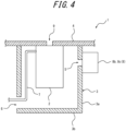
- a vacuum tube support structure 1 includes a vacuum tube 2, a cover 3 that covers the vacuum tube 2, and a support member 4 that supports the vacuum tube 2 and the cover 3.
- the cover 3 includes a fluid introduction port 5 that allows a fluid to pass through the cover 3 to introduce the fluid inside the cover 3 and a fluid discharge port 6 configured to allow the fluid to pass through the cover 3 to discharge the fluid from inside the cover 3.
- the fluid introduced through the fluid introduction port 5 contacts the vacuum tube 2 and is discharged through the fluid discharge port 6.
- the cover 3 covering the vacuum tube 2 can protect the surrounding area from high voltage applied to the vacuum tube 2. Furthermore, the fluid introduced inside the cover 3 from the fluid introduction port 5 comes in contact with the vacuum tube 2 and thus removes the heat generated by the vacuum tube 2. The fluid is then discharged from inside the cover 3 through the fluid discharge port 6, thereby suppressing a rise in temperature inside the cover 3. Therefore, a vacuum tube support structure 1 such that the internal temperature does not rise easily can be achieved. As a result, deterioration of the vacuum tube 2 can be suppressed, and the amount of work to replace the vacuum tube 2, for example, can be reduced.
- the fluid discharge port 6 allows wiring 7 of the vacuum tube 2 to pass through the fluid discharge port 6. According to this configuration, the fluid discharge port 6 can also serve as a passage for the wiring 7 of the vacuum tube 2, thereby simplifying the vacuum tube support structure 1.
- the vacuum tube support structure 1 includes a fluid supply apparatus 8, and the fluid supply apparatus 8 supplies the fluid to the fluid introduction port 5. According to this configuration, fluid can be easily introduced inside the cover 3 by the fluid supply apparatus 8.
- the fluid supply apparatus 8 includes piping 8a connecting to the fluid introduction port 5, and the piping 8a supplies the fluid to the fluid introduction port 5. According to this configuration, the piping 8a can be used to introduce the fluid from a desired location to the fluid introduction port 5.
- the fluid supply apparatus 8 may be configured to include a fan 8b that sends the fluid. According to this configuration, the structure of the fluid supply apparatus 8 can be simplified, since the fluid can be sent to the fluid introduction port 5 by the fan 8b.
- the fluid supply apparatus 8 may be configured to include a cooling apparatus 8c capable of cooling the fluid. According to this configuration, since the cooling apparatus 8c can supply cooled fluid, a vacuum tube support structure 1 such that the internal temperature does not rise easily can be achieved.
- the fluid supply apparatus 8 may be configured to include a temperature adjustment apparatus capable of adjusting the temperature of the fluid. According to this configuration, since the temperature adjustment apparatus can supply an appropriately cooled fluid, the temperature inside the vacuum tube support structure 1 can be appropriately controlled.
- the vacuum tube support structure 1 may be configured to include a fluid discharge apparatus, and the fluid discharge apparatus may discharge the fluid from the fluid discharge port 6. According to this configuration, fluid can be easily discharged from inside the cover 3 by the fluid discharge apparatus.
- the fluid discharge apparatus may be configured to include piping 8a that connects to the fluid discharge port 6, and the piping 8a may discharge the fluid from the fluid discharge port 6.
- the piping 8a can be used to discharge the fluid from the fluid discharge port 6 to a desired location.
- the fluid discharge apparatus may be configured to include a fan 8b that sends the fluid. According to this configuration, the structure of the fluid discharge apparatus can be simplified, since the fluid can be discharged from the fluid discharge port 6 by the fan 8b.
- the cover 3 includes a peripheral wall member 3a, which has one end supported by the support member 4, and an end member 3b provided at the other end of the peripheral wall member 3a. According to this configuration, the cover 3 can be achieved with a simple structure.
- the fluid introduction port 5 and the fluid discharge port 6 are located in the peripheral wall member 3a. According to this configuration, the heat generated by the vacuum tube 2 can be efficiently removed, and a rise in temperature inside the cover 3 can be further suppressed.
- the vacuum tube 2 is an x-ray tube that emits x-rays. X-ray tubes are particularly prone to deterioration due to heat generation. Therefore, deterioration can be significantly suppressed by using the vacuum tube support structure 1 according to this configuration, in which the internal temperature does not rise easily.
- the vacuum tube 2 is not limited to being an x-ray tube but may also be configured to emit electromagnetic waves other than x-rays.
- the vacuum tube support structure 1 includes an electromagnetic wave transmission space 9 that allows electromagnetic waves emitted by the vacuum tube 2 to be transmitted through the vacuum tube support structure 1 for emission from within the vacuum tube support structure 1. According to this configuration, electromagnetic waves can be emitted through the electromagnetic wave transmission space 9. As illustrated in FIGS. 3 and 4 , the support member 4 includes the electromagnetic wave transmission space 9, but this configuration is not limiting.
- a sensor 10 includes the vacuum tube support structure 1 and measures a physical quantity of a measurement target 11 by receiving electromagnetic waves irradiated from the vacuum tube 2 toward the measurement target 11.
- the sensor 10 includes a transmitter 12 that includes the vacuum tube support structure 1 and irradiates electromagnetic waves from the vacuum tube 2 toward the measurement target 11 and a receiver 13 that receives the electromagnetic waves irradiated toward the measurement target 11. According to this configuration, it is possible to achieve a sensor 10 that includes a vacuum tube support structure 1 such that the internal temperature does not rise easily.
- the senor 10 is a transmission-type sensor such that the transmitter 12 and the receiver 13 are installed on different sides as viewed from the measurement target 11, but this configuration is not limiting.
- the sensor 10 may also be configured as a reflection-type sensor such that the transmitter 12 and the receiver 13 are installed on the same side as viewed from the measurement target 11.
- the sensor 10 includes a power source 14 that supplies power to the vacuum tube 2, and the power source 14 is supported by the support member 4. According to this configuration, the structure of the sensor 10 can be simplified.
- a measurement apparatus 15 includes the sensor 10 and a movement apparatus 16 that moves the sensor 10 in a direction intersecting (see the double bold arrows in FIG. 1 ) the direction of movement (see the bold arrow in FIG. 1 ) of the measurement target 11. According to this configuration, it is possible to achieve a measurement apparatus 15 that includes a vacuum tube support structure 1 such that the internal temperature does not rise easily.
- the measurement apparatus 15 is installed on a production line along which the measurement target 11 flows. According to the this configuration, a physical quantity of the measurement target 11 can be measured on the production line.
- the measurement apparatus 15 is configured as a thickness gauge, such as a basis weight meter, that measures the thickness of the measurement target 11 by the intensity of the electromagnetic waves received by the receiver 13. According to this configuration, it is possible to achieve a thickness gauge that includes a vacuum tube support structure 1 such that the internal temperature does not rise easily.
Landscapes
- Physics & Mathematics (AREA)
- Engineering & Computer Science (AREA)
- Electromagnetism (AREA)
- General Physics & Mathematics (AREA)
- Mechanical Engineering (AREA)
- Combustion & Propulsion (AREA)
- Chemical & Material Sciences (AREA)
- Thermal Sciences (AREA)
- General Engineering & Computer Science (AREA)
- Measuring Fluid Pressure (AREA)
- X-Ray Techniques (AREA)
- Thermal Insulation (AREA)
- External Artificial Organs (AREA)
- Jet Pumps And Other Pumps (AREA)
Applications Claiming Priority (1)
| Application Number | Priority Date | Filing Date | Title |
|---|---|---|---|
| JP2023084819A JP2024168278A (ja) | 2023-05-23 | 2023-05-23 | 真空管支持構造 |
Publications (2)
| Publication Number | Publication Date |
|---|---|
| EP4468828A2 true EP4468828A2 (de) | 2024-11-27 |
| EP4468828A3 EP4468828A3 (de) | 2025-06-04 |
Family
ID=90885804
Family Applications (1)
| Application Number | Title | Priority Date | Filing Date |
|---|---|---|---|
| EP24172481.4A Pending EP4468828A3 (de) | 2023-05-23 | 2024-04-25 | Stützstruktur für vakuumröhre |
Country Status (4)
| Country | Link |
|---|---|
| US (1) | US20240397602A1 (de) |
| EP (1) | EP4468828A3 (de) |
| JP (1) | JP2024168278A (de) |
| CN (1) | CN119028791A (de) |
Families Citing this family (1)
| Publication number | Priority date | Publication date | Assignee | Title |
|---|---|---|---|---|
| CN121736553A (zh) | 2024-09-27 | 2026-03-27 | 柯尼卡美能达株式会社 | 喷墨用墨 |
Family Cites Families (8)
| Publication number | Priority date | Publication date | Assignee | Title |
|---|---|---|---|---|
| US1992335A (en) * | 1932-12-30 | 1935-02-26 | Kelley Koett Mfg Company | Shock-proof X-ray tube unit |
| DE3888388T2 (de) * | 1987-05-07 | 1994-06-23 | Picker Int Inc | Gerät für Röntgenaufnahme. |
| JP2002124396A (ja) * | 2000-08-18 | 2002-04-26 | Marconi Medical Systems Inc | 解除可能な電気的結合装置及び方法 |
| WO2006090323A2 (en) * | 2005-02-24 | 2006-08-31 | Philips Intellectual Property & Standards Gmbh | Computer tomography apparatus with multiple x-ray radiation sources |
| JP4880771B2 (ja) * | 2010-07-21 | 2012-02-22 | 株式会社ジョブ | X線発生装置 |
| JP6214899B2 (ja) * | 2012-03-30 | 2017-10-18 | 東芝電子管デバイス株式会社 | 回転陽極型x線管ユニット及び回転陽極型x線管装置 |
| JP7091654B2 (ja) * | 2017-12-26 | 2022-06-28 | 横河電機株式会社 | X線式坪量測定装置 |
| JP2020013715A (ja) * | 2018-07-19 | 2020-01-23 | キヤノン電子管デバイス株式会社 | X線管装置及びx線コンピュータ断層撮影装置 |
-
2023
- 2023-05-23 JP JP2023084819A patent/JP2024168278A/ja active Pending
-
2024
- 2024-04-19 CN CN202410474158.6A patent/CN119028791A/zh active Pending
- 2024-04-25 EP EP24172481.4A patent/EP4468828A3/de active Pending
- 2024-05-06 US US18/655,734 patent/US20240397602A1/en active Pending
Also Published As
| Publication number | Publication date |
|---|---|
| JP2024168278A (ja) | 2024-12-05 |
| CN119028791A (zh) | 2024-11-26 |
| US20240397602A1 (en) | 2024-11-28 |
| EP4468828A3 (de) | 2025-06-04 |
Similar Documents
| Publication | Publication Date | Title |
|---|---|---|
| US9281155B2 (en) | Radiation generating apparatus and radiation imaging apparatus | |
| US7887237B2 (en) | Cooling system for gantry-mounted components of a computed tomography system | |
| US20240397602A1 (en) | Vacuum tube support structure | |
| US9058958B2 (en) | Radiation generating apparatus and radiation imaging apparatus | |
| US7619374B2 (en) | Radiotherapy system for performing radiotherapy with presice irradiation | |
| JP2017027873A (ja) | X線発生装置及びx線撮影システム | |
| JP2013020791A5 (de) | ||
| WO2013032019A1 (en) | X-ray generator and x-ray imaging apparatus | |
| EP2995905A1 (de) | Röntgenstrahlvorrichtung und herstellungsverfahren für eine struktur | |
| EP2333528A3 (de) | Röntgenstrahlenmessvorrichtung | |
| US10504679B2 (en) | X-ray generating apparatus and radiography system including the same | |
| JP6122796B2 (ja) | X線厚さ計 | |
| CN110650777A (zh) | 中子捕捉疗法系统 | |
| JPWO2019151251A1 (ja) | X線管の制御方法及びx線管の制御装置 | |
| US20140294150A1 (en) | Radiation generating apparatus and radiographing system using the same | |
| JP2019115422A (ja) | 放射線撮影装置及び放射線撮影システム | |
| JP5194261B2 (ja) | X線管装置 | |
| WO2006009053A1 (ja) | 固定陽極x線管とそれを用いたx線検査装置及びx線照射装置 | |
| US10438766B2 (en) | X-ray emitter | |
| US9711322B2 (en) | X-ray tube device | |
| KR101817989B1 (ko) | 멀티소스를 갖는 x선 촬영장치 | |
| EP2277003B1 (de) | Dickemessvorrichtung für metallblech und diesbezügliches messverfahren | |
| JP2020013715A (ja) | X線管装置及びx線コンピュータ断層撮影装置 | |
| JP2011196837A (ja) | X線測定装置 | |
| JP2024118762A (ja) | X線厚み測定装置 |
Legal Events
| Date | Code | Title | Description |
|---|---|---|---|
| PUAI | Public reference made under article 153(3) epc to a published international application that has entered the european phase |
Free format text: ORIGINAL CODE: 0009012 |
|
| STAA | Information on the status of an ep patent application or granted ep patent |
Free format text: STATUS: THE APPLICATION HAS BEEN PUBLISHED |
|
| AK | Designated contracting states |
Kind code of ref document: A2 Designated state(s): AL AT BE BG CH CY CZ DE DK EE ES FI FR GB GR HR HU IE IS IT LI LT LU LV MC ME MK MT NL NO PL PT RO RS SE SI SK SM TR |
|
| PUAL | Search report despatched |
Free format text: ORIGINAL CODE: 0009013 |
|
| AK | Designated contracting states |
Kind code of ref document: A3 Designated state(s): AL AT BE BG CH CY CZ DE DK EE ES FI FR GB GR HR HU IE IS IT LI LT LU LV MC ME MK MT NL NO PL PT RO RS SE SI SK SM TR |
|
| RIC1 | Information provided on ipc code assigned before grant |
Ipc: G01B 15/02 20060101ALI20250429BHEP Ipc: G01B 7/00 20060101ALI20250429BHEP Ipc: H05G 1/04 20060101ALI20250429BHEP Ipc: H05G 1/02 20060101AFI20250429BHEP |
|
| STAA | Information on the status of an ep patent application or granted ep patent |
Free format text: STATUS: REQUEST FOR EXAMINATION WAS MADE |
|
| 17P | Request for examination filed |
Effective date: 20251104 |