EP4468064A2 - Dreidimensionale anzeige mit mehreren tiefenebenen mit einem wellenleiterreflektorarrayprojektor - Google Patents
Dreidimensionale anzeige mit mehreren tiefenebenen mit einem wellenleiterreflektorarrayprojektor Download PDFInfo
- Publication number
- EP4468064A2 EP4468064A2 EP24205494.8A EP24205494A EP4468064A2 EP 4468064 A2 EP4468064 A2 EP 4468064A2 EP 24205494 A EP24205494 A EP 24205494A EP 4468064 A2 EP4468064 A2 EP 4468064A2
- Authority
- EP
- European Patent Office
- Prior art keywords
- light
- reflectors
- micro
- wave guide
- wave
- Prior art date
- Legal status (The legal status is an assumption and is not a legal conclusion. Google has not performed a legal analysis and makes no representation as to the accuracy of the status listed.)
- Pending
Links
Images









Classifications
-
- G—PHYSICS
- G02—OPTICS
- G02B—OPTICAL ELEMENTS, SYSTEMS OR APPARATUS
- G02B27/00—Optical systems or apparatus not provided for by any of the groups G02B1/00 - G02B26/00, G02B30/00
- G02B27/01—Head-up displays
- G02B27/017—Head mounted
-
- G—PHYSICS
- G02—OPTICS
- G02B—OPTICAL ELEMENTS, SYSTEMS OR APPARATUS
- G02B30/00—Optical systems or apparatus for producing three-dimensional [3D] effects, e.g. stereoscopic images
- G02B30/50—Optical systems or apparatus for producing three-dimensional [3D] effects, e.g. stereoscopic images the image being built up from image elements distributed over a three-dimensional [3D] volume, e.g. voxels
-
- G—PHYSICS
- G02—OPTICS
- G02B—OPTICAL ELEMENTS, SYSTEMS OR APPARATUS
- G02B6/00—Light guides; Structural details of arrangements comprising light guides and other optical elements, e.g. couplings
- G02B6/04—Light guides; Structural details of arrangements comprising light guides and other optical elements, e.g. couplings formed by bundles of fibres
- G02B6/06—Light guides; Structural details of arrangements comprising light guides and other optical elements, e.g. couplings formed by bundles of fibres the relative position of the fibres being the same at both ends, e.g. for transporting images
-
- G—PHYSICS
- G02—OPTICS
- G02B—OPTICAL ELEMENTS, SYSTEMS OR APPARATUS
- G02B6/00—Light guides; Structural details of arrangements comprising light guides and other optical elements, e.g. couplings
- G02B6/24—Coupling light guides
- G02B6/26—Optical coupling means
- G02B6/262—Optical details of coupling light into, or out of, or between fibre ends, e.g. special fibre end shapes or associated optical elements
-
- G—PHYSICS
- G02—OPTICS
- G02F—OPTICAL DEVICES OR ARRANGEMENTS FOR THE CONTROL OF LIGHT BY MODIFICATION OF THE OPTICAL PROPERTIES OF THE MEDIA OF THE ELEMENTS INVOLVED THEREIN; NON-LINEAR OPTICS; FREQUENCY-CHANGING OF LIGHT; OPTICAL LOGIC ELEMENTS; OPTICAL ANALOGUE/DIGITAL CONVERTERS
- G02F1/00—Devices or arrangements for the control of the intensity, colour, phase, polarisation or direction of light arriving from an independent light source, e.g. switching, gating or modulating; Non-linear optics
- G02F1/01—Devices or arrangements for the control of the intensity, colour, phase, polarisation or direction of light arriving from an independent light source, e.g. switching, gating or modulating; Non-linear optics for the control of the intensity, phase, polarisation or colour
- G02F1/011—Devices or arrangements for the control of the intensity, colour, phase, polarisation or direction of light arriving from an independent light source, e.g. switching, gating or modulating; Non-linear optics for the control of the intensity, phase, polarisation or colour in optical waveguides, not otherwise provided for in this subclass
-
- G—PHYSICS
- G02—OPTICS
- G02B—OPTICAL ELEMENTS, SYSTEMS OR APPARATUS
- G02B27/00—Optical systems or apparatus not provided for by any of the groups G02B1/00 - G02B26/00, G02B30/00
- G02B27/01—Head-up displays
- G02B27/0101—Head-up displays characterised by optical features
- G02B2027/0127—Head-up displays characterised by optical features comprising devices increasing the depth of field
-
- G—PHYSICS
- G02—OPTICS
- G02B—OPTICAL ELEMENTS, SYSTEMS OR APPARATUS
- G02B6/00—Light guides; Structural details of arrangements comprising light guides and other optical elements, e.g. couplings
- G02B6/0001—Light guides; Structural details of arrangements comprising light guides and other optical elements, e.g. couplings specially adapted for lighting devices or systems
- G02B6/0011—Light guides; Structural details of arrangements comprising light guides and other optical elements, e.g. couplings specially adapted for lighting devices or systems the light guides being planar or of plate-like form
- G02B6/0013—Means for improving the coupling-in of light from the light source into the light guide
- G02B6/0023—Means for improving the coupling-in of light from the light source into the light guide provided by one optical element, or plurality thereof, placed between the light guide and the light source, or around the light source
- G02B6/0028—Light guide, e.g. taper
-
- G—PHYSICS
- G02—OPTICS
- G02B—OPTICAL ELEMENTS, SYSTEMS OR APPARATUS
- G02B6/00—Light guides; Structural details of arrangements comprising light guides and other optical elements, e.g. couplings
- G02B6/0001—Light guides; Structural details of arrangements comprising light guides and other optical elements, e.g. couplings specially adapted for lighting devices or systems
- G02B6/0011—Light guides; Structural details of arrangements comprising light guides and other optical elements, e.g. couplings specially adapted for lighting devices or systems the light guides being planar or of plate-like form
- G02B6/0033—Means for improving the coupling-out of light from the light guide
- G02B6/0035—Means for improving the coupling-out of light from the light guide provided on the surface of the light guide or in the bulk of it
-
- G—PHYSICS
- G02—OPTICS
- G02B—OPTICAL ELEMENTS, SYSTEMS OR APPARATUS
- G02B6/00—Light guides; Structural details of arrangements comprising light guides and other optical elements, e.g. couplings
- G02B6/0001—Light guides; Structural details of arrangements comprising light guides and other optical elements, e.g. couplings specially adapted for lighting devices or systems
- G02B6/0011—Light guides; Structural details of arrangements comprising light guides and other optical elements, e.g. couplings specially adapted for lighting devices or systems the light guides being planar or of plate-like form
- G02B6/0075—Arrangements of multiple light guides
-
- G—PHYSICS
- G02—OPTICS
- G02B—OPTICAL ELEMENTS, SYSTEMS OR APPARATUS
- G02B6/00—Light guides; Structural details of arrangements comprising light guides and other optical elements, e.g. couplings
- G02B6/0001—Light guides; Structural details of arrangements comprising light guides and other optical elements, e.g. couplings specially adapted for lighting devices or systems
- G02B6/0011—Light guides; Structural details of arrangements comprising light guides and other optical elements, e.g. couplings specially adapted for lighting devices or systems the light guides being planar or of plate-like form
- G02B6/0075—Arrangements of multiple light guides
- G02B6/0076—Stacked arrangements of multiple light guides of the same or different cross-sectional area
-
- G—PHYSICS
- G02—OPTICS
- G02B—OPTICAL ELEMENTS, SYSTEMS OR APPARATUS
- G02B6/00—Light guides; Structural details of arrangements comprising light guides and other optical elements, e.g. couplings
- G02B6/0001—Light guides; Structural details of arrangements comprising light guides and other optical elements, e.g. couplings specially adapted for lighting devices or systems
- G02B6/0011—Light guides; Structural details of arrangements comprising light guides and other optical elements, e.g. couplings specially adapted for lighting devices or systems the light guides being planar or of plate-like form
- G02B6/0075—Arrangements of multiple light guides
- G02B6/0078—Side-by-side arrangements, e.g. for large area displays
Definitions
- a light field encompasses all the light rays at every point in space traveling in every direction. Light fields are considered four dimensional because every point in a three-dimensional space also has an associated direction, which is the fourth dimension.
- Wearable three-dimensional displays may include a substrate guided optical device, also known as the light-guide optical element (LOE) system.
- LOE light-guide optical element
- Such devices are manufactured by, for example Lumus Ltd.
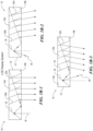
- the LOE system 10 uses a single layer wave guide 12 made of two parallel planar surfaces 14a, 14b.
- Light 16 is coupled into the LOE wave guide 12 using a mini-projector (not shown) and reflector strip 18.
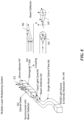
- FIGS 1B-1, 1B-2 and 1B-3 illustrate the wave guide 12 of the LOE system 10, showing light 16 entering at three respective angles
- the LOE system 10 uses planar micro-reflectors 20a-20n (only two called out for sake of drawing clarity) that are only oriented along one angular direction and are positioned parallel to one another. However, the LOE system 10 only projects a single depth plane, focused at infinity, with a spherical wave front curvature of zero.
- the invention is directed to the following items.
- WRAP wave guide reflector array projector
- the ability of the humans to perceive depth of field in a scene is limited, that is, humans have limited visual resolution at different radial distances. Consequently, to recreate an object or scene so that a user experiences the full 3D effect, not every possible focal plane in the 3D volume needs to be recreated.
- the 3D volume can be recreated for human perception by simply reproducing a limited number of slices of a particular 3D volume.
- Theories as to the number of slices that need to be recreated range from less than 16 to 36 or more, where the width of the slices are thinnest for distances closer to the eye and increase with distance.
- the human vision system i.e. eyes, retinal nerve, brain focally collapses each of these planes so that additional slices of information presented are not necessary for the human to perceive the 3D volume.
- the basic assumption is that only a finite number of slices of a 3D volume need to be reproduced for a human to perceive the full 3D effect.
- An optical apparatus or system may be employed to, for example, generate or project light to simulate a four dimensional (4D) light field that would be produced by light reflecting from a real three-dimensional object or scene.
- an optical apparatus such as a wave guide reflector array projector (WRAP) apparatus or multiple depth plane three dimensional (3D) display system may generate or project multiple virtual depth planes at respective radial focal distances to simulate a 4D light field.
- the optical apparatus in the form of a WRAP apparatus or multiple depth plane 3D display system may, for instance, project images into each eye of a user, either directly or indirectly.
- a discrete set of projected depth planes mimics the psycho-physical effect that is produced by a real, continuous, three dimensional object or scene.
- an optical apparatus in the form of a WRAP apparatus or multiple depth plane 3D display system 500 may include a 2D array 502 of a plurality of wave guides 504a-504n (collectively 504, only two called out for drawing clarity).
- each of the wave guides 504 may have a rectangular cross section taken across a length or longitudinal axis thereof (the longitudinal axis denominated herein as x axis).
- the wave guides 504 may be arranged in a plurality of columns 506 ⁇ e.g., xy planes, extending vertically in the view of FIG.
- the columns 506 may be characterized as two-dimensional (2D) wave guides or sets of wave guides (each identified with reference number 506).
- the 2D wave guides 506 may be stacked as layers, for example along a first lateral axis, denominated herein as z axis. As explained herein, each 2D planar wave guide, set of wave guides, layer or column 506 produces or generates a respective virtual depth plane at a respective distance to produce a 4D light field.
- the WRAP apparatus or multiple depth plane 3D display system 500 may include one or more components to provide one or more optical paths to, or from, the wave guides 504.
- a set of distribution wave guides 510a-510n (collectively 510, only two called out for drawing clarity).
- the distribution wave guides may provide an optical path to wave guides 504 in respective columns or layers 506.
- the WRAP apparatus or multiple depth plane 3D display system 500 may include a plurality of optical couplers (e.g. , optical fibers) illustrated by arrows 512 (referenced collectively) that provide an optical path to respective ones of the distribution wave guides 510 (i.e., each respective column 508).
- the WRAP apparatus or multiple depth plane 3D display system 500 may include a single optical coupler (e.g. , optical fibers) illustrated by arrow 514 that provides an optical path to two, more or all of the distribution wave guides 510.
- the distribution wave guides 510 and/or optical couplers 512, 514 may, for example provide input to the wave guides 504 of the 2D array 502, for instance as a pixel pattern from a source of red/green/blue (RGB) light (not illustrated in FIG. 5A .
- RGB red/green/blue
- each column or wave guide layer 506a-506c produces a respective slice or virtual depth plane 522a-522c (only three shown, collectively 522) having a spherical wave front 524a-524c (only three shown, collectively 524) to cumulatively simulate a 4D light field 526.
- a position of a respective virtual point source 528a-528c (only three shown, collectively 528) for each of the virtual depth planes 522a-522c is also illustrated.
- FIG. 3A shows a single column, 2D planar wave guide, column, layer or set of wave guides 506, along with its respective distribution coupler 510 and an optical coupler 512, 514, according to one illustrated embodiment,
- Each of the 2D planar wave guides or layers 506 are comprised of a plurality of linear wave guides 504e, 504f (collectively 504, only two called out for drawing clarity).
- the 2D planar wave guides 506 may, for example, each include a series or linear array of rectangular cylindrical wave guides 504, sometimes referred to as wave guide tubes.
- tubes While sometimes denominated as “tubes” one of skill in the art will readily appreciate that such structures do not need to be hollow, and in many implementations will be solid, similar in many respects to optical fibers but having at least one pair of opposed planar surfaces, which are at least partially internally reflective to propagate electromagnetic energy (e.g., light) along a length 530 of the wave guide 504.
- the at least one pair of opposed planar surfaces 532a, 532b may substantially internally reflect certain defined modes of light while allowing certain other defined modes of light to substantially pass out of the wave guide 504.
- the wave guide 504 will include two pairs of opposed planar surfaces 532a/532b, 532c/532d (collectively 532), which are partially internally reflective, for example substantially internally reflective of certain defined modes.
- substantially means more than 50 percent, and typically more than 85 percent or 95 percent.
- the wave guides 504 of the 2D planar wave guide, layer, column or set 506 may be formed individually and assembled or coupled together.
- the wave guides 504 of the 2D planar wave guide, layer, column or set 506 may be formed as a single unitary structure. Planar surfaces may facilitate production of the desired depth planes and/or increase the density of packing the wave guides 504 into a 3D structure.
- each linear wave guide 504 Embedded, located or formed within each linear wave guide 504 is a series of deconstructed curved spherical reflectors or mirrors 540a-540n (only two of the curved micro-reflectors called out for clarity of drawing) that are designed to refocus infinity-focused light at specific radial distances. It is noted that in the interest of drawing clarity, the full micro-reflectors of a single linear array of only one of the linear wave guides 504 are fully illustrated in broken line, the micro-reflectors of other linear arrays of other linear wave guides 504 represented schematically by simple convex curves. A number of micro-reflectors 504A-504D for a single linear or rectangular wave guide 504n are represented in FIG. 5A .
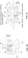
- FIG. 1A shows an example of how an input plane wave 100 focused at infinity can be reflected from a convex spherical mirror 102 to produce an output spherical wave 104 to represent a virtual point source 106 which appears to be located at a defined distance behind the convex spherical mirror 102.
- a series of micro-reflectors 540 whose shapes ⁇ e.g., radii of curvature about two axes) and orientation together project a 3D image that corresponds to a spherical wave front produced by a virtual point source at a particular x, y, z, coordinate.
- Each of the 2D wave guides or layers 506 provides an independent optical path relative to the other wave guides, and shapes the wave front and focuses incoming light to project a virtual depth plane 522 ( FIG. 5C ) that corresponds to a respective radial distance.
- a virtual depth plane 522 FIG. 5C
- a user viewing the projected virtual depth planes experiences a 3D effect.
- FIGS. 5A-5C shows a portion of an example multiple layer WRAP display apparatus or system 500 with 2D planar wave guides, columns or sets of wave guides 506 stacked as layers.
- Each layer 506 includes multiple wave guides, for instance linear or rectangular wave guides 504, as shown in the example of FIG. 3A .
- a set of optical distribution couplers 510 and/or other optical couplers 512, 514 optically couple the linear or rectangular wave guides 504 of the 2D array 502, to other components.
- the optical distribution couplers 510 and/or other optical couplers 512, 514 may optically couple the linear or rectangular wave guides 504 of the 2D array 502 to a subsystem that provides pixel patterns ⁇ e.g., RGB intensity modulated pixel patterns).
- the set of optical couplers 510 are referred to herein and/or in the claims as a linear array of column distribution couplers or as second lateral (Y) axis distribution optical couplers, or coupling tubes.
- Y second lateral
- Each individual wave guide 504 in the WRAP apparatus 500 includes a series of deconstructed curved spherical reflectors or mirrors 540 that are designed to refocus infinity-focused light at specific radial distances.
- a Fresnel lens is an example of a macroscopic optical element constructed from a series of optical micro-components.
- the WRAP apparatus 500 includes an array of micro-reflectors 540 that operate effectively as a side- injected ⁇ e.g., injected from a side denominated as the first end) Fresnel mirror.
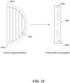
- FIG. 18 illustrates an example of an array of micro-reflectors 1802a- 1802n (collectively 1802, only two called out for drawing clarity) in the configuration of a portion of a sphere 1804 rather than an array of micro- reflectors 1806a-1806n (collectively 1806, only two called out for drawing clarity) in a linear configuration 1808 as would be found in the equivalent Fresnel mirror, where the orientation of the micro-reflectors 1802 in the sphere configuration 1804 matches the orientation of the micro-components or micro-reflectors 1806 of the linear Fresnel mirror configuration 1808.
- the WRAP apparatus 500 includes an array of curved micro- reflectors in the linear or rectangular wave guides 504 that comprise each of the 2D wave guides 506.
- the array of curved micro-reflectors are positioned and oriented to act similarly to a lens or curved mirror, to project virtual images at specified radial distances. While denominated herein and/or in the claims as "reflectors," as explained herein the curved micro-reflectors typically partially reflect and partially pass electromagnetic energy, for instance optical wavelengths of light (i.e., Near Infrared or N-IR, visible, Near Ultraviolet or N-UV). As described herein, the reflectance may be a function of an angular mode of the electromagnetic energy or light.
- Conventional lens-based imaging systems or curved mirror-based imaging systems use optical elements with large surface curvatures.
- Conventional lens-based imaging systems or curved mirror-based imaging systems are front- or back-injected, typically by a wide light field from a projector element.
- Such conventional systems tend to be relatively thick and heavy, and often use multiple optical elements and moving parts to vary their focal lengths.
- the illustrated 2D array 502 ( FIG. 5A ) of linear wave guides 504 of the WRAP apparatus 500 has a planar surface.
- the illustrated 2D array 502 of linear wave guides 504 of the WRAP apparatus 500 may be side-injected (i.e., injected into side denominated herein and in the claims as a first end) by a cone 542 ( FIG.
- the illustrated 2D array 502 of linear wave guides 504 of the WRAP apparatus 500 may be can be made very thin and light.
- the illustrated 2D planar wave guides or layers 506 may be easily stacked to create a multifocal display in which each 2D planar wave guide, layer, column or set 506 provides optical paths independently of other 2D planar wave guides, layers, columns or sets, for example allowing each to provide a respective focal or depth plane in a 3D image.
- the WRAP apparatus 500 projects multiple depth planes 522 ( FIG. 5C ), each focused at a different radial distance with the corresponding spherical wave front curvatures 524 ( FIG. 5C ).
- the WRAP apparatus 500 may include a series of linear or rectangular cylindrical wave guides arranged in vertical (xy) columns to create a planar 2D wave guide 506, which is some instances may be referred to as a 2D assembly of linear or rectangular wave guides 503.
- the WRAP apparatus 500 may include multiple 2D planar wave guides, columns, layers or sets 506, each corresponding to a different virtual depth plane 522 ( FIG. 5C ).
- the WRAP apparatus 500 may use convex spherically curved micro- reflectors 540 ( FIGS. 3A and 5A ).
- the micro-reflectors 540 may have one or more surface curvatures, and the surface curvatures may vary in each wave guide layer 506.
- each of the micro- reflectors 540 may be oriented along two angular directions ⁇ , O.
- the angular directions ⁇ , O may vary in any given linear wave guide 504 or may vary between linear wave guides 504 in a single layer 506 or between different layers 506.
- light may be coupled to the 2D array 503 of the WRAP apparatus 500 from one or more RGB (red, green, blue) light sources 544, for example via one or more of a light intensity modulator 546, fiber optic cables 548, angular mode modulator or beam deflector 550, optional optical demultiplexing switch for instance implemented via optical gates 552, optional z-axis coupling array 554, and the previously described and illustrated separate set of y-axis optical couplers or optical coupling array 510.
- RGB red, green, blue
- a WRAP apparatus 500 may include a stack of thin, planar, 2D wave guides 506 that are themselves made up of horizontal rows of linear or rectangular cylindrical wave guides 504. While denominated as 2D, the 2D wave guides 506 physically have depth, but are denominated as such since each represents a 2D slice or portion (i.e., column) of the 2D array 502.
- the 2D array of wave guides physically have a length, but are denominated as such since the length is an inherent property of the individual linear or rectangular wave guides 504 which may up the 2D array 502, Likewise, while sometimes referred to as a linear wave guide 504, these wave guides physically have heights and widths, but are denominated as such since each provides a linear optical path.
- FIG. 3A shows an example single layer of the 2D array 503 of a WRAP apparatus 500.
- An input cone 542 of light is directed via an optical fiber 512, 514, 548 into a distribution optical coupler or y-axis optical coupler 510, sometimes referred to herein as a coupling tube (oriented vertically in FIG. 3A ).
- a distribution optical coupler or y-axis optical coupler 510 mounted in a row within the optical coupler 510 are a number of multiple beam splitters 556a-556n (collectively 556, only two called out in interest of drawing clarity).
- Each beam splitter 556v reflects a first portion of the light incident upon it to one of multiple stacked linear or rectangular wave guides 504 (oriented horizontally in FIG.
- light incident into the distribution optical coupler or y-axis optical coupler 510 is emitted into multiple linear or rectangular wave guides 504 positioned along at least a portion of a length of the distribution optical coupler or y-axis optical coupler 510.
- each linear or rectangular wave guide 504 embedded, positioned or formed in each linear or rectangular wave guide 504 is a linear array of curved micro- reflectors 540 that are shaped and angularly oriented such that each angled light beam that is guided through the linear or rectangular wave guide 504 is projected from the linear or rectangular wave guide 504 by the micro- reflectors 540 into a three dimensional curved pattern.
- FIG. 3B shows example orientation angles ⁇ , O of micro-reflectors 540 in a wave guide, where the micro-reflectors are represented in planar form for ease if illustration.
- FIG. 3C shows an example of orientation angles ⁇ , O for a curved micro-reflector 540.
- the projected pattern corresponds to the spherical wave front that is produced by a virtual point source placed at a given x,y,z coordinate, with the x and y coordinates being determined by the 2D angular orientation of the light beam, and the z-coordinate being determined by the particular configuration of micro-reflector shapes and 2D orientation gradients in a given 2D planar wave guide, column, layer or set 506.
- Each 2D planar wave guide, column, layer or set 506 is configured to have different wave front shaping and focusing properties such that each layer projects a virtual depth plane corresponding to a different z-coordinate, or radial coordinate (r-coordinate).
- a point source of light that is placed at a given x,y,z coordinate produces a radiating three dimensional pattern of light that varies in a very specific way throughout three dimensional space.
- the point source generates a spherical wave front whose surface curvature varies in inverse proportion to the radius of the radiating sphere.
- the WRAP apparatus 500 is designed to generate a section of this sphere with the appropriate wave front curvature and two dimensional rotation, for a particular z-coordinate, upon receiving the input ray that corresponds to a given x, y coordinate.
- each WRAP 2D planar wave guide, column, layer or set 506 may be provided via a separate multi-mode optical fiber 512 into which a small cone 542 of light has been injected.
- light input to each 2D planar wave guide, column, layer or set 506 is in the form of the light cone 542 via a respective output channel 514 of a demultiplexing switch 552 ( FIG. 8 ).
- the light cone 542 contains a two dimensional angular distribution of light beams that corresponds to the two dimensional x, y light intensity pattern that is present in a single depth plane of a 3D volume to be re-created.
- There are a number of ways to couple the angular distribution of the light cone into the input fiber such as using a MEMS scanner, a switchable liquid crystal, or a MEMS diffraction grating.
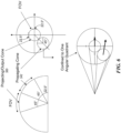
- the propagating light cone 542 should have a defined or known angular pattern, for example as shown in the example of FIG. 6 .
- the light cone 542 that propagates inside of the linear or rectangular wave guide 504 should lie approximately in the angular range of -22.5 degrees to -67.5 degrees, in both angular directions, and the light cone 560 that is projected out of the wave guide should lie approximately in the angular range of -22.5 degrees to +22.5 degrees, in both angular directions.
- the angular range of the input image should be limited accordingly. Light that is propagated outside of these angular ranges will produce aliasing and double images.
- each wave guide layer 506 is driven by a different multi-mode fiber 512 that propagates an angular pattern corresponding to that portion of the visual field which is contained in a particular depth layer volume.
- These angular patterns are generated by drive electronics ⁇ e.g., RGB light source, intensity modulator) that are located in a base unit and then sent to the 2D array 502 in parallel over multiple multi-mode fibers 512.
- drive electronics e.g., RGB light source, intensity modulator
- 2D images can be angularly encoded using a scanning projector system (such as the scanning fiber projector) or by coupling a 2D micro-projector to a pinhole aperture.
- the angular pattern for the entire visual field is simultaneously created and sorted amongst the different wave guide layers 506, one angular beam at a time, using optical gates 552 that are synchronized with a 2D beam deflector 550 that creates the pattern. Because this process takes place at the 2D array 502, distribution or y-axis optical coupler 510 and/or z-axis optical coupler 562 ( FIG. 9 ), and not in a base unit, it can be driven by a single single-mode fiber 514. In this system, input images are angularly encoded such that each resolvable angle that propagates through a fiber or other wave guide 514 corresponds to an intensity of a single object point.
- multi-mode fibers 514 and optical couplers 514, 562 are used that are able to propagate numerous angular modes with an angular density that is comparable to the linear resolution of the display.
- the angular range of the light cone corresponds to the maximum field of view of the optical apparatus 500, for example, 45 degrees.
- FIG. 9 shows an example illustration of light propagation through a portion of a WRAP apparatus which includes a z-axis optical coupler 562.
- FIG. 9 represents the relative orientations of the z-axis optical coupler 562, the distribution or y-axis optical coupler 510, and the linear or rectangular wave guides (interchangeably referred to as x-axis wave guides) 504.
- light initially enters via the z-axis optical coupler 562.
- the z-axis optical coupler may be similar in many respects to the linear or rectangular wave guides, for example having at least one pair of opposed planar sides that provide at least partial internal reflection to propagate or guide light along a length of the z-axis optical coupler 562.
- the z-axis optical coupler 562 contains a linear array of angled, planar micro-reflectors 564a- 564n (collectively 564) that multiply and inject copies of the incoming angular distribution of light into each of the distribution or y-axis optical couplers 510 of the various columns, sets or layers 506.
- the distribution or y-axis optical couplers 510 may be similar in construction to the z-axis optical coupler 562, having a linear array of angled, planar micro-reflectors 566a-566n (collectively 566).
- the distribution or y-axis optical couplers 510 multiplies and injects copies of the incoming angular distribution of light into each of the x-axis wave guides 504 in the respective column, set or layer 506.
- narrow, angled, plane wave light beam 566 enters the linear or rectangular wave guide 504, reflecting from a planar reflector 568 toward at least one of the opposed reflective surfaces 532.
- the plane wave light beam is split into two beams.
- a first beam continues to the next micro-reflector 540, and a second beam is reflected in a divergent pattern with a curvature that is twice as great as that of a surface of the micro-reflector 540 from which the second beam reflected.
- a narrow incident plane wave is converted into a small wedge-like section of a spherical wave front that has a 2D orientation that corresponds to that of the incident plane wave.
- all of the spherical wave front wedges that are projected from each micro-reflector 540 can be aligned into a single spherical wave front 569 that appears to be radiating from a virtual point 570 located at the x and y coordinates that correspond to the 2D orientation of the plane wave 566 and the z-coordinate that corresponds to the curvature(s) of the micro-reflector 540 and 2D orientation gradient of the 2D wave guide, column, set or layer 506, as shown in FIG. 2B .
- FIGS. 13-15 show coordinate systems for virtual object points, a 4D light field on a display surface, and 2
- depth planes are sufficiently numerous and have the appropriate thicknesses as a function of their radial distance (as determined by the depth of field equation), such that if the depth planes meet or exceed the limits of human z-coordinate resolution (as well as x, y coordinate resolution), then the light field that is generated from a virtual 3D volume should be indistinguishable to a human from that of a real, physical, three dimensional space.
- each 2D wave guide, plane, set or layer 506 is mutually unaffected by the other 2D wave guide, plane, set or layers 506. This feature allows the 2D wave guide, plane, set or layers 506 to be stacked on top of each other to create a multifocal optical system, a feature which is not believe to be possible with conventional lenses.
- orthogonal light polarization can be used to decouple light from the real outside world from that of the virtual display to create an augmented reality multiple depth plane 3D display.
- Polarized reflectors 540 only reflect that portion of light which is aligned parallel to the axis of polarization of the reflector.
- Cross polarized light is not reflected by the reflector 540, and in the case of a semi-transparent reflector 540, would simply pass through the reflector without being reflected.
- a 2D wave guide, plane, set or layer 506 can be made transparent to light from the outside world or to other 2D wave guide, plane, set or layers 506 simply by cross polarizing the 2D wave guide, plane, set or layer's 506 light.
- a z-axis optical coupler 562 ( FIG. 9 ) can be equipped with optical gates 522 that are synchronized with the beam deflector 550 to sort the light beams from a multiplexed input cone 542 into multiple output channel cones 572 (only one called out in FIG. 8 for clarity of drawing) that correspond to each of the depth plane in the virtual 3D volume 1604.
- the 2D array 502 is driven by a single single-mode fiber 514, 548, and the light cones 572 that correspond to the different 2D wave guide, plane, set or layers 506 are generated within the device itself.
- the light angles should be simultaneously created and sorted, one angle at a time. If the light angles are not created in a time sequential manner, the light angles cannot easily be sorted into each of the 2D wave guide, plane, set or layers 506.
- the optical apparatus 500 can be viewed as a mathematical operator that transforms 2D light fields into 4D light fields.
- FIG. 4 shows example details of the transformation.
- the optical apparatus 500 performs the transformation by applying a positive curvature to each of the light beams in an input cone 402 and mapping 406 a 2D array of differentially rotated copies of the modified light cone onto a surface of a display. These operations are physically generated by the array(s) of micro-reflectors 540 and have the effect of transforming narrow, plane wave light beams into wide, spherical wave fronts 404; converting light cones into virtual depth planes; and generating a 3D volume from a stack of two dimensional projections, as shown in the example of FIG. 12 . (For comparison, FIGS.
- FIG. 4 and 12 also show an input cone 408 generated into a flat wave front 410.
- FIG. 13 shows a coordinate system 1300 for virtual object points.
- FIG. 14 shows a coordinate system 1400 for a 4D light field on a display surface.
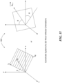
- FIG. 15 shows a coordinate system 1500 for two-dimensional micro-reflector orientations.
- linear or rectangular wave guides 504 function as beam multipliers and wideners that mathematically and physically generate a wide 2D array of light beams based on the input of a single, narrow light beam.
- FIG. 19 illustrates how a light cone 1902a1902d (collectively 1902) is multiplied through the use of multiple beam splitters that transmit a portion of incident light and reflect a portion of the incident light.
- micro-reflectors ⁇ e.g., curved micro-reflectors 504) should be partially transparent and perform the function of a beam splitter as well as a reflector. In this way, a single beam of light having a narrow range of angles can be repeatedly multiplied and redistributed through the array to create a wide 4D light field.
- the reflectances of the reflective surfaces (e.g. 532) of the wave guides ⁇ e.g., linear or rectangular wave guides 504) and the micro- reflectors (e.g., curved micro-reflectors 504) should be angle specific. Specifically, the micro-reflectors (e.g., curved micro-reflectors 504) should only reflect the angular modes of the input cone that are internally reflected from the surface ⁇ e.g., 532) of the wave guide (e.g., linear or rectangular wave guides 504), and should be transparent to all other angular modes.
- Each wave guide ⁇ e.g., linear or rectangular wave guides 504) should only be transparent to the angular modes which are reflected from the micro- reflectors (e.g., curved micro-reflectors 504) and should confine all other angular modes to the interior of the wave guide (e.g., linear or rectangular wave guides 504). This allows the light from the input cone to be distributed throughout the entire length of the wave guide (e.g., linear or rectangular wave guides 504) and to be coupled to each of the micro-reflectors (e.g., curved micro-reflectors 504) before being projected out of the 2D array 502.
- micro-reflectors e.g., curved micro- reflectors 504
- wave guides e.g., linear or rectangular wave guides 504
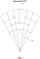
- FOV maximum field of view
- the field of view 700 of the optical apparatus 500 will be less than 45 degrees to accommodate the beam curvature that is produced by the micro-reflectors 540, as shown in FIG. 7 .
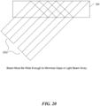
- the light beams that are coupled into the linear or rectangular wave guides 504 should be wide enough so that the micro-reflectors 540 are evenly covered by the light beams, and gaps and irregularities in the output are minimized.
- FIG. 20 shows an example where the width of the light beam 2002 is not wide enough to prevent gaps in the light beam array.
- the light from the input cone should be polarized along a single axis, and the micro-reflectors 540 and reflective opposed surfaces 532 of the wave guides 504 should only reflect light that is polarized along the same axis.
- an exterior side of the display should have an orthogonally polarizing screen (not shown), such as a liquid crystal display, that allows the user to adjust the real-virtual contrast, i.e., the relative light intensities of the real and virtual visual fields.
- the orthogonally polarizing screen can also orthogonally polarize the light from the real world relative to the polarization axis of the virtual display, thus allowing the light to pass through the display without being affected by the micro-reflectors 540 or reflective opposed surfaces 532 of the linear or rectangular wave guides 504.
- phase differences and incoherence that is brought about by variations in path length, transit time and wavelength should be undetectable by the human visual system.
- each 2D planar wave guide, column, set or layer 506 of the 2D array 502 should be as thin as possible. For example, in one embodiment with 10 layers, a thickness of approximately 1 mm per layer would work for the wearable device. With a larger number of layers, e.g., 25 to 35, near and far light fields can be fully recreated. However, fewer than 10 or greater than 35 layers can be used.
- each 2D planar wave guide, column, set or layer 506 can be reconfigured in real-time, i.e., the curvature(s) of the micro-reflector(s) 504 and/or 2D orientation gradient can be dynamically varied in a rapid manner.
- the projection of each virtual depth layer can be time multiplexed, instead of being presented simultaneously.
- a single layer N-plane display system should be reconfigured at a rate N times that of the refresh rate of a single layer in an N-layer system.
- Dynamically configurable curved micro-reflectors 504a may be employed.
- two dimensional liquid crystal surfaces can be used, where the shapes and orientations of the surfaces can be controlled with electric and/or magnetic fields, as shown in the example of FIG. 10 .
- electrically and/or magnetically deformable microfluids can be used as the micro-reflectors 504b, where the shapes and orientations can be dynamically changed, as shown in the example of FIG. 17 .
- transparent display screens whose pixels 540b are able to project light in specified directions can be used to change the direction of the projected light, for instance as shown in the examples of the bottom of FIG. 10 and FIG. 1 1 .
- FIG. 21 is a flow diagram illustrating an example process 2100 of re-creating a three-dimensional volume on a display by driving a multiple layer wave guide in parallel.
- the optical apparatus 502 receives multiple input light beams.
- Each of the multiple light beams can be delivered by a multi-mode optical fiber.
- Each of the multiple input light beams corresponds to an intensity pattern of a portion of a visual field in a different layer of the three-dimensional volume to be recreated.
- the system creates a set of intermediate light beams from each of the multiple input light beams.
- the system independently rotates copies of the set of multiple intermediate light beams, and at block 2120, projects a wave front that appears to radiate from a virtual point. All of the projected wave fronts together recreate the 3D volume for viewing by the user.
- the words “comprise,” “comprising,” and the like are to be construed in an inclusive sense (i.e., to say, in the sense of “including, but not limited to”), as opposed to an exclusive or exhaustive sense.
- the terms “connected,” “coupled,” or any variant thereof means any connection or coupling, either direct or indirect, between two or more elements. Such a coupling or connection between the elements can be physical, logical, or a combination thereof.
- the words “herein,” “above,” “below,” and words of similar import when used in this application, refer to this application as a whole and not to any particular portions of this application.
Landscapes
- Physics & Mathematics (AREA)
- General Physics & Mathematics (AREA)
- Optics & Photonics (AREA)
- Nonlinear Science (AREA)
- Optical Elements Other Than Lenses (AREA)
- Mechanical Light Control Or Optical Switches (AREA)
- Optical Couplings Of Light Guides (AREA)
- Liquid Crystal (AREA)
- Projection Apparatus (AREA)
- Light Guides In General And Applications Therefor (AREA)
- Testing, Inspecting, Measuring Of Stereoscopic Televisions And Televisions (AREA)
- Optical Modulation, Optical Deflection, Nonlinear Optics, Optical Demodulation, Optical Logic Elements (AREA)
- Electrochromic Elements, Electrophoresis, Or Variable Reflection Or Absorption Elements (AREA)
- Optical Integrated Circuits (AREA)
Applications Claiming Priority (4)
| Application Number | Priority Date | Filing Date | Title |
|---|---|---|---|
| US201261658355P | 2012-06-11 | 2012-06-11 | |
| PCT/US2013/045267 WO2013188464A1 (en) | 2012-06-11 | 2013-06-11 | Multiple depth plane three-dimensional display using a wave guide reflector array projector |
| EP22195536.2A EP4130820B1 (de) | 2012-06-11 | 2013-06-11 | Dreidimensionale anzeige mit mehreren tiefenebenen mit einem wellenleiterreflektorarrayprojektor |
| EP13803879.9A EP2859403B1 (de) | 2012-06-11 | 2013-06-11 | Dreidimensionales display mit mehreren tiefenebenen und einem wellenleiter-reflektorarray-projektor |
Related Parent Applications (2)
| Application Number | Title | Priority Date | Filing Date |
|---|---|---|---|
| EP13803879.9A Division EP2859403B1 (de) | 2012-06-11 | 2013-06-11 | Dreidimensionales display mit mehreren tiefenebenen und einem wellenleiter-reflektorarray-projektor |
| EP22195536.2A Division EP4130820B1 (de) | 2012-06-11 | 2013-06-11 | Dreidimensionale anzeige mit mehreren tiefenebenen mit einem wellenleiterreflektorarrayprojektor |
Publications (2)
| Publication Number | Publication Date |
|---|---|
| EP4468064A2 true EP4468064A2 (de) | 2024-11-27 |
| EP4468064A3 EP4468064A3 (de) | 2024-12-11 |
Family
ID=49758682
Family Applications (3)
| Application Number | Title | Priority Date | Filing Date |
|---|---|---|---|
| EP13803879.9A Active EP2859403B1 (de) | 2012-06-11 | 2013-06-11 | Dreidimensionales display mit mehreren tiefenebenen und einem wellenleiter-reflektorarray-projektor |
| EP24205494.8A Pending EP4468064A3 (de) | 2012-06-11 | 2013-06-11 | Dreidimensionale anzeige mit mehreren tiefenebenen mit einem wellenleiterreflektorarrayprojektor |
| EP22195536.2A Active EP4130820B1 (de) | 2012-06-11 | 2013-06-11 | Dreidimensionale anzeige mit mehreren tiefenebenen mit einem wellenleiterreflektorarrayprojektor |
Family Applications Before (1)
| Application Number | Title | Priority Date | Filing Date |
|---|---|---|---|
| EP13803879.9A Active EP2859403B1 (de) | 2012-06-11 | 2013-06-11 | Dreidimensionales display mit mehreren tiefenebenen und einem wellenleiter-reflektorarray-projektor |
Family Applications After (1)
| Application Number | Title | Priority Date | Filing Date |
|---|---|---|---|
| EP22195536.2A Active EP4130820B1 (de) | 2012-06-11 | 2013-06-11 | Dreidimensionale anzeige mit mehreren tiefenebenen mit einem wellenleiterreflektorarrayprojektor |
Country Status (10)
| Country | Link |
|---|---|
| US (1) | US9310559B2 (de) |
| EP (3) | EP2859403B1 (de) |
| JP (2) | JP6238974B2 (de) |
| KR (2) | KR102217788B1 (de) |
| CN (4) | CN115494654B (de) |
| AU (4) | AU2013274359B2 (de) |
| CA (1) | CA2876335C (de) |
| IL (3) | IL236176A0 (de) |
| NZ (1) | NZ702897A (de) |
| WO (1) | WO2013188464A1 (de) |
Families Citing this family (367)
| Publication number | Priority date | Publication date | Assignee | Title |
|---|---|---|---|---|
| IL166799A (en) | 2005-02-10 | 2014-09-30 | Lumus Ltd | Aluminum shale surfaces for use in a conductive substrate |
| US10073264B2 (en) | 2007-08-03 | 2018-09-11 | Lumus Ltd. | Substrate-guide optical device |
| US10261321B2 (en) | 2005-11-08 | 2019-04-16 | Lumus Ltd. | Polarizing optical system |
| GB0522968D0 (en) | 2005-11-11 | 2005-12-21 | Popovich Milan M | Holographic illumination device |
| GB0718706D0 (en) | 2007-09-25 | 2007-11-07 | Creative Physics Ltd | Method and apparatus for reducing laser speckle |
| US9335604B2 (en) | 2013-12-11 | 2016-05-10 | Milan Momcilo Popovich | Holographic waveguide display |
| US11726332B2 (en) | 2009-04-27 | 2023-08-15 | Digilens Inc. | Diffractive projection apparatus |
| US11204540B2 (en) | 2009-10-09 | 2021-12-21 | Digilens Inc. | Diffractive waveguide providing a retinal image |
| US20200057353A1 (en) | 2009-10-09 | 2020-02-20 | Digilens Inc. | Compact Edge Illuminated Diffractive Display |
| US9274349B2 (en) | 2011-04-07 | 2016-03-01 | Digilens Inc. | Laser despeckler based on angular diversity |
| US10670876B2 (en) | 2011-08-24 | 2020-06-02 | Digilens Inc. | Waveguide laser illuminator incorporating a despeckler |
| WO2016020630A2 (en) | 2014-08-08 | 2016-02-11 | Milan Momcilo Popovich | Waveguide laser illuminator incorporating a despeckler |
| EP2748670B1 (de) | 2011-08-24 | 2015-11-18 | Rockwell Collins, Inc. | Tragbare datenanzeige |
| US20150010265A1 (en) | 2012-01-06 | 2015-01-08 | Milan, Momcilo POPOVICH | Contact image sensor using switchable bragg gratings |
| EP2842003B1 (de) | 2012-04-25 | 2019-02-27 | Rockwell Collins, Inc. | Holographisches weitwinkeldisplay |
| US9456744B2 (en) | 2012-05-11 | 2016-10-04 | Digilens, Inc. | Apparatus for eye tracking |
| IL219907A (en) | 2012-05-21 | 2017-08-31 | Lumus Ltd | Integrated head display system with eye tracking |
| US9671566B2 (en) | 2012-06-11 | 2017-06-06 | Magic Leap, Inc. | Planar waveguide apparatus with diffraction element(s) and system employing same |
| US9122966B2 (en) | 2012-09-07 | 2015-09-01 | Lawrence F. Glaser | Communication device |
| US11593776B2 (en) | 2012-09-07 | 2023-02-28 | Studebaker & Brackett PC | Communication device to sense one or more biometric characteristics of a user |
| US10044985B1 (en) * | 2012-10-19 | 2018-08-07 | Amazon Technologies, Inc. | Video monitoring using plenoptic cameras and mirrors |
| US9933684B2 (en) | 2012-11-16 | 2018-04-03 | Rockwell Collins, Inc. | Transparent waveguide display providing upper and lower fields of view having a specific light output aperture configuration |
| US10209517B2 (en) | 2013-05-20 | 2019-02-19 | Digilens, Inc. | Holographic waveguide eye tracker |
| US10262462B2 (en) | 2014-04-18 | 2019-04-16 | Magic Leap, Inc. | Systems and methods for augmented and virtual reality |
| WO2015006784A2 (en) | 2013-07-12 | 2015-01-15 | Magic Leap, Inc. | Planar waveguide apparatus with diffraction element(s) and system employing same |
| US10533850B2 (en) | 2013-07-12 | 2020-01-14 | Magic Leap, Inc. | Method and system for inserting recognized object data into a virtual world |
| US9727772B2 (en) | 2013-07-31 | 2017-08-08 | Digilens, Inc. | Method and apparatus for contact image sensing |
| US11402629B2 (en) | 2013-11-27 | 2022-08-02 | Magic Leap, Inc. | Separated pupil optical systems for virtual and augmented reality and methods for displaying images using same |
| KR102177133B1 (ko) | 2014-01-31 | 2020-11-10 | 매직 립, 인코포레이티드 | 멀티-포컬 디스플레이 시스템 및 방법 |
| US10203762B2 (en) | 2014-03-11 | 2019-02-12 | Magic Leap, Inc. | Methods and systems for creating virtual and augmented reality |
| US10430985B2 (en) | 2014-03-14 | 2019-10-01 | Magic Leap, Inc. | Augmented reality systems and methods utilizing reflections |
| US11138793B2 (en) | 2014-03-14 | 2021-10-05 | Magic Leap, Inc. | Multi-depth plane display system with reduced switching between depth planes |
| WO2015145119A1 (en) * | 2014-03-24 | 2015-10-01 | Wave Optics Ltd | Display system |
| IL232197B (en) | 2014-04-23 | 2018-04-30 | Lumus Ltd | Compact head-up display system |
| NZ764905A (en) * | 2014-05-30 | 2022-05-27 | Magic Leap Inc | Methods and systems for generating virtual content display with a virtual or augmented reality apparatus |
| US10852838B2 (en) | 2014-06-14 | 2020-12-01 | Magic Leap, Inc. | Methods and systems for creating virtual and augmented reality |
| GB2529003B (en) * | 2014-08-03 | 2020-08-26 | Wave Optics Ltd | Optical device |
| WO2016020632A1 (en) | 2014-08-08 | 2016-02-11 | Milan Momcilo Popovich | Method for holographic mastering and replication |
| WO2016042283A1 (en) | 2014-09-19 | 2016-03-24 | Milan Momcilo Popovich | Method and apparatus for generating input images for holographic waveguide displays |
| EP3198192A1 (de) | 2014-09-26 | 2017-08-02 | Milan Momcilo Popovich | Optischer tracker mit holografischem wellenleiter |
| WO2016054079A1 (en) | 2014-09-29 | 2016-04-07 | Zyomed Corp. | Systems and methods for blood glucose and other analyte detection and measurement using collision computing |
| AU2015323940B2 (en) | 2014-09-29 | 2021-05-20 | Magic Leap, Inc. | Architectures and methods for outputting different wavelength light out of waveguides |
| IL235642B (en) | 2014-11-11 | 2021-08-31 | Lumus Ltd | A compact head-up display system is protected by an element with a super-thin structure |
| US10154239B2 (en) | 2014-12-30 | 2018-12-11 | Onpoint Medical, Inc. | Image-guided surgery with surface reconstruction and augmented reality visualization |
| US10437064B2 (en) | 2015-01-12 | 2019-10-08 | Digilens Inc. | Environmentally isolated waveguide display |
| EP3245551B1 (de) | 2015-01-12 | 2019-09-18 | DigiLens Inc. | Lichtfeldanzeigen mit wellenleiter |
| CN107533137A (zh) | 2015-01-20 | 2018-01-02 | 迪吉伦斯公司 | 全息波导激光雷达 |
| US9632226B2 (en) | 2015-02-12 | 2017-04-25 | Digilens Inc. | Waveguide grating device |
| CN106034232B (zh) | 2015-03-12 | 2018-03-23 | 北京智谷睿拓技术服务有限公司 | 显示控制方法和装置 |
| WO2016146963A1 (en) | 2015-03-16 | 2016-09-22 | Popovich, Milan, Momcilo | Waveguide device incorporating a light pipe |
| NZ773822A (en) | 2015-03-16 | 2022-07-29 | Magic Leap Inc | Methods and systems for diagnosing and treating health ailments |
| US10591756B2 (en) | 2015-03-31 | 2020-03-17 | Digilens Inc. | Method and apparatus for contact image sensing |
| CN106293557B (zh) | 2015-05-04 | 2019-12-03 | 北京智谷睿拓技术服务有限公司 | 显示控制方法和装置 |
| NZ775650A (en) | 2015-05-04 | 2023-06-30 | Magic Leap Inc | Separated pupil optical systems for virtual and augmented reality and methods for displaying images using same |
| CN106293561B (zh) | 2015-05-28 | 2020-02-28 | 北京智谷睿拓技术服务有限公司 | 显示控制方法和装置、显示设备 |
| CN106303315B (zh) | 2015-05-30 | 2019-08-16 | 北京智谷睿拓技术服务有限公司 | 视频显示控制方法和装置、显示设备 |
| CN106303499B (zh) | 2015-05-30 | 2018-10-16 | 北京智谷睿拓技术服务有限公司 | 视频显示控制方法和装置、显示设备 |
| CN106303498B (zh) | 2015-05-30 | 2018-10-16 | 北京智谷睿拓技术服务有限公司 | 视频显示控制方法和装置、显示设备 |
| IL256276B (en) | 2015-06-15 | 2022-09-01 | Magic Leap Inc | Display system with optical components for coupling multiple light streams |
| US10685488B1 (en) | 2015-07-17 | 2020-06-16 | Naveen Kumar | Systems and methods for computer assisted operation |
| US10176642B2 (en) | 2015-07-17 | 2019-01-08 | Bao Tran | Systems and methods for computer assisted operation |
| US10492981B1 (en) | 2015-07-17 | 2019-12-03 | Bao Tran | Systems and methods for computer assisted operation |
| US10149958B1 (en) | 2015-07-17 | 2018-12-11 | Bao Tran | Systems and methods for computer assisted operation |
| US10335572B1 (en) | 2015-07-17 | 2019-07-02 | Naveen Kumar | Systems and methods for computer assisted operation |
| AU2016296723B2 (en) * | 2015-07-20 | 2021-03-04 | Magic Leap, Inc. | Collimating fiber scanner design with inward pointing angles in virtual/augmented reality system |
| JP6503963B2 (ja) | 2015-07-29 | 2019-04-24 | オムロン株式会社 | 光デバイス |
| JP2017032673A (ja) * | 2015-07-30 | 2017-02-09 | 日本電気硝子株式会社 | 導光板及びこれを用いた積層導光板 |
| KR102689919B1 (ko) | 2015-08-18 | 2024-07-30 | 매직 립, 인코포레이티드 | 가상 및 증강 현실 시스템들 및 방법들 |
| KR102726941B1 (ko) | 2015-08-21 | 2024-11-05 | 매직 립, 인코포레이티드 | 눈꺼풀 형상 추정 |
| CN108135469B (zh) | 2015-08-21 | 2021-03-09 | 奇跃公司 | 使用眼睛姿态测量的眼睑形状估计 |
| KR102351060B1 (ko) | 2015-09-16 | 2022-01-12 | 매직 립, 인코포레이티드 | 오디오 파일들의 헤드 포즈 혼합 |
| CN108351527B (zh) | 2015-09-23 | 2024-06-18 | 奇跃公司 | 采用离轴成像器的眼睛成像 |
| WO2017062483A1 (en) * | 2015-10-05 | 2017-04-13 | Magic Leap, Inc. | Microlens collimator for scanning optical fiber in virtual/augmented reality system |
| WO2017060665A1 (en) | 2015-10-05 | 2017-04-13 | Milan Momcilo Popovich | Waveguide display |
| IL304501B2 (en) | 2015-10-06 | 2024-08-01 | Magic Leap Inc | A virtual/augmented reality system with an inverted angle refraction grating |
| EP3362946B1 (de) | 2015-10-16 | 2020-08-26 | Magic Leap, Inc. | Identifizierung der augenposition anhand von augenmerkmalen |
| CN113220116A (zh) | 2015-10-20 | 2021-08-06 | 奇跃公司 | 改变可穿戴设备用户输入模式的系统和方法及可穿戴系统 |
| WO2017079329A1 (en) * | 2015-11-04 | 2017-05-11 | Magic Leap, Inc. | Dynamic display calibration based on eye-tracking |
| US11231544B2 (en) | 2015-11-06 | 2022-01-25 | Magic Leap, Inc. | Metasurfaces for redirecting light and methods for fabricating |
| US10204451B2 (en) | 2015-11-30 | 2019-02-12 | Microsoft Technology Licensing, Llc | Multi-optical surface optical design |
| KR102439768B1 (ko) | 2016-01-07 | 2022-09-01 | 매직 립, 인코포레이티드 | 심도 평면들에 걸쳐 분포된 동일하지 않은 수의 컴포넌트 컬러 이미지들을 갖는 가상 및 증강 현실 시스템들 및 방법들 |
| US10831264B2 (en) | 2016-01-19 | 2020-11-10 | Magic Leap, Inc. | Eye image combination |
| CN118605029A (zh) | 2016-01-19 | 2024-09-06 | 奇跃公司 | 利用映像的增强现实系统和方法 |
| CN108474904B (zh) | 2016-01-20 | 2021-07-06 | 奇跃公司 | 虚拟/增强现实系统中的偏振保持光纤 |
| WO2017127897A1 (en) * | 2016-01-27 | 2017-08-03 | Paul Lapstun | Shuttered waveguide light field display |
| CA3013025A1 (en) | 2016-01-29 | 2017-08-03 | Magic Leap, Inc. | Display for three-dimensional image |
| US10429639B2 (en) | 2016-01-31 | 2019-10-01 | Paul Lapstun | Head-mounted light field display |
| US11445305B2 (en) | 2016-02-04 | 2022-09-13 | Magic Leap, Inc. | Technique for directing audio in augmented reality system |
| EP3398007B1 (de) | 2016-02-04 | 2024-09-11 | DigiLens, Inc. | Optischer wellenleitertracker |
| CA3007511C (en) | 2016-02-04 | 2023-09-19 | Magic Leap, Inc. | Technique for directing audio in augmented reality system |
| IL260939B2 (en) * | 2016-02-11 | 2023-10-01 | Magic Leap Inc | Multi-depth planar display system with limited change between depth planes |
| IL303148A (en) | 2016-02-24 | 2023-07-01 | Magic Leap Inc | Low profile connection for light emitter |
| US10302957B2 (en) | 2016-02-24 | 2019-05-28 | Magic Leap, Inc. | Polarizing beam splitter with low light leakage |
| CA3015210A1 (en) | 2016-02-26 | 2017-08-31 | Magic Leap, Inc. | Display system having a plurality of light pipes for a plurality of light emitters |
| EP3420601B1 (de) | 2016-02-26 | 2023-08-02 | Magic Leap, Inc. | Optisches system |
| CN108700712B (zh) * | 2016-02-29 | 2020-10-13 | 奇跃公司 | 虚拟和增强现实系统及方法 |
| EP3423887B1 (de) | 2016-03-01 | 2023-07-12 | Magic Leap, Inc. | Reflexionsschaltungsvorrichtung zur eingabe unterschiedlicher wellenlängen von licht in wellenleiter |
| CN114690881A (zh) | 2016-03-04 | 2022-07-01 | 奇跃公司 | 减少用电的显示系统以及用于减少显示系统的用电的方法 |
| CA3016189A1 (en) | 2016-03-07 | 2017-09-14 | Magic Leap, Inc. | Blue light adjustment for biometric security |
| CN111329552B (zh) | 2016-03-12 | 2021-06-22 | P·K·朗 | 包括机器人的用于引导骨切除的增强现实可视化 |
| CN105589202A (zh) * | 2016-03-18 | 2016-05-18 | 京东方科技集团股份有限公司 | 一种显示装置、显示方法和显示系统 |
| CA3017795A1 (en) | 2016-03-22 | 2017-09-28 | Magic Leap, Inc. | Head mounted display system configured to exchange biometric information |
| JP6895451B2 (ja) | 2016-03-24 | 2021-06-30 | ディジレンズ インコーポレイテッド | 偏光選択ホログラフィー導波管デバイスを提供するための方法および装置 |
| US10698215B2 (en) | 2016-03-25 | 2020-06-30 | Magic Leap, Inc. | Virtual and augmented reality systems and methods |
| US9411167B1 (en) | 2016-03-29 | 2016-08-09 | Kedrick F. Brown | Auto-multiscopic 3D billboard display system |
| US9554738B1 (en) | 2016-03-30 | 2017-01-31 | Zyomed Corp. | Spectroscopic tomography systems and methods for noninvasive detection and measurement of analytes using collision computing |
| KR102438052B1 (ko) | 2016-03-31 | 2022-08-29 | 매직 립, 인코포레이티드 | 포즈들 및 멀티-dof 제어기들을 사용하는 3d 가상 객체들과 상호작용들 |
| US10317679B2 (en) | 2016-04-04 | 2019-06-11 | Akonia Holographics, Llc | Light homogenization |
| EP3440497B1 (de) | 2016-04-08 | 2023-08-16 | Magic Leap, Inc. | Systeme der erweiterten realität und verfahren mit linsenelementen mit veränderlicher brennweite |
| EP3433658B1 (de) | 2016-04-11 | 2023-08-09 | DigiLens, Inc. | Holographische wellenleitervorrichtung für die projektion von strukturiertem licht |
| JP7118007B2 (ja) | 2016-04-21 | 2022-08-15 | マジック リープ, インコーポレイテッド | 視野周辺の視覚的背光 |
| NZ747815A (en) | 2016-04-26 | 2023-05-26 | Magic Leap Inc | Electromagnetic tracking with augmented reality systems |
| US10046229B2 (en) | 2016-05-02 | 2018-08-14 | Bao Tran | Smart device |
| JP6961619B2 (ja) | 2016-05-06 | 2021-11-05 | マジック リープ, インコーポレイテッドMagic Leap, Inc. | 光を再指向させるための非対称格子を有するメタ表面および製造方法 |
| AU2017264695B2 (en) | 2016-05-09 | 2022-03-31 | Magic Leap, Inc. | Augmented reality systems and methods for user health analysis |
| US9904058B2 (en) | 2016-05-12 | 2018-02-27 | Magic Leap, Inc. | Distributed light manipulation over imaging waveguide |
| WO2017201329A1 (en) | 2016-05-20 | 2017-11-23 | Magic Leap, Inc. | Contextual awareness of user interface menus |
| US9491444B2 (en) | 2016-05-27 | 2016-11-08 | Kedrick F. Brown | Auto-multiscopic 3D display system |
| KR20240036149A (ko) | 2016-06-03 | 2024-03-19 | 매직 립, 인코포레이티드 | 증강 현실 아이덴티티 검증 |
| CN117028910A (zh) | 2016-06-10 | 2023-11-10 | 奇跃公司 | 纹理投射灯泡的积分点光源 |
| US10332315B2 (en) | 2016-06-20 | 2019-06-25 | Magic Leap, Inc. | Augmented reality display system for evaluation and modification of neurological conditions, including visual processing and perception conditions |
| CA3029541A1 (en) | 2016-06-30 | 2018-01-04 | Magic Leap, Inc. | Estimating pose in 3d space |
| EP3270208B1 (de) | 2016-07-12 | 2024-03-06 | Essilor International | Verfahren zur bereitstellung einer anzeigevorrichtung für ein elektronisches informationsgerät |
| US10296792B2 (en) | 2016-07-14 | 2019-05-21 | Magic Leap, Inc. | Iris boundary estimation using cornea curvature |
| KR102648770B1 (ko) | 2016-07-14 | 2024-03-15 | 매직 립, 인코포레이티드 | 홍채 식별을 위한 딥 뉴럴 네트워크 |
| AU2017301435B2 (en) | 2016-07-25 | 2022-07-14 | Magic Leap, Inc. | Imaging modification, display and visualization using augmented and virtual reality eyewear |
| KR102723374B1 (ko) | 2016-07-25 | 2024-10-29 | 매직 립, 인코포레이티드 | 광 필드 프로세서 시스템 |
| KR102639135B1 (ko) | 2016-07-29 | 2024-02-20 | 매직 립, 인코포레이티드 | 암호화방식으로 싸인된 레코드들의 안전한 교환 |
| IL303843B2 (en) | 2016-08-11 | 2024-06-01 | Magic Leap Inc | Automatic placement of a virtual object in a three-dimensional space |
| AU2017308914B2 (en) | 2016-08-12 | 2021-12-09 | Magic Leap, Inc. | Word flow annotation |
| WO2018039273A1 (en) | 2016-08-22 | 2018-03-01 | Magic Leap, Inc. | Dithering methods and apparatus for wearable display device |
| EP3500911B1 (de) | 2016-08-22 | 2023-09-27 | Magic Leap, Inc. | Anzeigevorrichtung mit erweiterter realität mit tiefenlernsensoren |
| KR102324728B1 (ko) * | 2016-09-07 | 2021-11-10 | 매직 립, 인코포레이티드 | 두꺼운 미디어를 포함하는 가상 현실, 증강 현실 및 혼합 현실 시스템들 및 관련된 방법들 |
| KR101894556B1 (ko) * | 2016-09-08 | 2018-10-04 | 주식회사 레티널 | 광학 장치 |
| CA3036208A1 (en) | 2016-09-13 | 2018-03-22 | Magic Leap, Inc. | Sensory eyewear |
| IL293629B2 (en) * | 2016-09-21 | 2024-03-01 | Magic Leap Inc | Systems and methods for optical systems with exit pupil expander |
| KR102786412B1 (ko) | 2016-09-22 | 2025-03-25 | 매직 립, 인코포레이티드 | 증강 현실 분광기 |
| US10534043B2 (en) | 2016-09-26 | 2020-01-14 | Magic Leap, Inc. | Calibration of magnetic and optical sensors in a virtual reality or augmented reality display system |
| AU2017335736B2 (en) | 2016-09-28 | 2022-08-11 | Magic Leap, Inc. | Face model capture by a wearable device |
| RU2016138608A (ru) | 2016-09-29 | 2018-03-30 | Мэджик Лип, Инк. | Нейронная сеть для сегментации изображения глаза и оценки качества изображения |
| IL293688B2 (en) | 2016-10-04 | 2024-02-01 | Magic Leap Inc | Efficient data layouts for convolutional neural networks |
| KR102402467B1 (ko) | 2016-10-05 | 2022-05-25 | 매직 립, 인코포레이티드 | 혼합 현실 교정을 위한 안구주위 테스트 |
| JP7187022B2 (ja) * | 2016-10-09 | 2022-12-12 | ルムス エルティーディー. | 長方形導波路を使用する開口乗算器 |
| IL311451A (en) | 2016-10-21 | 2024-05-01 | Magic Leap Inc | System and method for displaying image content on multiple depth planes by providing multiple intrapupillary parallax fields of view |
| CN113031165B (zh) | 2016-11-08 | 2023-06-02 | 鲁姆斯有限公司 | 导光装置、其光学组件及其对应的生产方法 |
| JP6913164B2 (ja) | 2016-11-11 | 2021-08-04 | マジック リープ, インコーポレイテッドMagic Leap,Inc. | 完全な顔画像の眼球周囲およびオーディオ合成 |
| CN115097937B (zh) | 2016-11-15 | 2025-04-29 | 奇跃公司 | 用于长方体检测的深度学习系统 |
| EP3933547B1 (de) | 2016-11-16 | 2023-12-27 | Magic Leap, Inc. | Wärmeverwaltungssysteme für wearable-komponenten |
| KR102506485B1 (ko) | 2016-11-18 | 2023-03-03 | 매직 립, 인코포레이티드 | 넓은 입사 각도 범위들의 광을 방향전환시키기 위한 다중층 액정 회절 격자들 |
| IL312713A (en) | 2016-11-18 | 2024-07-01 | Magic Leap Inc | Waveguide light multiplexer using crossed gratings |
| KR102533671B1 (ko) | 2016-11-18 | 2023-05-16 | 매직 립, 인코포레이티드 | 공간 가변적 액정 회절 격자들 |
| US11067860B2 (en) | 2016-11-18 | 2021-07-20 | Magic Leap, Inc. | Liquid crystal diffractive devices with nano-scale pattern and methods of manufacturing the same |
| EP3548943B1 (de) * | 2016-11-29 | 2025-06-25 | Technische Universiteit Eindhoven | Zweidimensionales optisches strahllenkungsmodul |
| CN106371222A (zh) * | 2016-11-30 | 2017-02-01 | 苏州苏大维格光电科技股份有限公司 | 一种纳米透镜波导镜片和多景深三维显示装置 |
| KR20240038823A (ko) | 2016-12-01 | 2024-03-25 | 매직 립, 인코포레이티드 | 스캐닝 어레이 광 엔진을 갖는 프로젝터 |
| EP3548939A4 (de) | 2016-12-02 | 2020-11-25 | DigiLens Inc. | Wellenleitervorrichtung mit gleichmässiger ausgabebeleuchtung |
| JP7112399B2 (ja) | 2016-12-05 | 2022-08-03 | マジック リープ, インコーポレイテッド | 複合現実環境における仮想ユーザ入力制御 |
| US10531220B2 (en) | 2016-12-05 | 2020-01-07 | Magic Leap, Inc. | Distributed audio capturing techniques for virtual reality (VR), augmented reality (AR), and mixed reality (MR) systems |
| IL304304B2 (en) | 2016-12-08 | 2024-08-01 | Magic Leap Inc | Diffractive devices based on cholesteric liquid crystal |
| US9762892B2 (en) | 2016-12-11 | 2017-09-12 | Lightscope Media, Llc | Auto-multiscopic 3D display and camera system |
| US9955144B2 (en) | 2016-12-11 | 2018-04-24 | Lightscope Media, Llc | 3D display system |
| CA3046399A1 (en) | 2016-12-13 | 2018-06-21 | Magic Leap, Inc. | 3d object rendering using detected features |
| KR102170123B1 (ko) | 2016-12-14 | 2020-10-26 | 주식회사 엘지화학 | 차광막이 형성되어 있는 도파관 및 이의 제조방법 |
| KR102550742B1 (ko) | 2016-12-14 | 2023-06-30 | 매직 립, 인코포레이티드 | 표면 정렬 패턴들의 소프트-임프린트 복제를 이용한 액정들의 패터닝 |
| US10371896B2 (en) | 2016-12-22 | 2019-08-06 | Magic Leap, Inc. | Color separation in planar waveguides using dichroic filters |
| US10746999B2 (en) | 2016-12-28 | 2020-08-18 | Magic Leap, Inc. | Dual depth exit pupil expander |
| EP3563215A4 (de) | 2016-12-29 | 2020-08-05 | Magic Leap, Inc. | Automatische steuerung einer wearable-anzeigevorrichtung auf basis von externen bedingungen |
| KR102779144B1 (ko) | 2017-01-05 | 2025-03-10 | 매직 립, 인코포레이티드 | 플라즈마 에칭에 의한 고굴절률 유리들의 패터닝 |
| US10545346B2 (en) | 2017-01-05 | 2020-01-28 | Digilens Inc. | Wearable heads up displays |
| US10108014B2 (en) | 2017-01-10 | 2018-10-23 | Microsoft Technology Licensing, Llc | Waveguide display with multiple focal depths |
| EP3568783A4 (de) | 2017-01-11 | 2020-11-11 | Magic Leap, Inc. | Medizinischer assistent |
| EP3568070B1 (de) | 2017-01-16 | 2024-01-03 | Philipp K. Lang | Optische führung für chirurgische, medizinische und zahnmedizinische eingriffe |
| AU2018210527B2 (en) | 2017-01-23 | 2022-12-01 | Magic Leap, Inc. | Eyepiece for virtual, augmented, or mixed reality systems |
| US10841724B1 (en) | 2017-01-24 | 2020-11-17 | Ha Tran | Enhanced hearing system |
| IL307294A (en) | 2017-01-27 | 2023-11-01 | Magic Leap Inc | Diffraction gratings produced using a surface cell with differently oriented nanobeams |
| WO2018140502A1 (en) | 2017-01-27 | 2018-08-02 | Magic Leap, Inc. | Antireflection coatings for metasurfaces |
| US11500143B2 (en) | 2017-01-28 | 2022-11-15 | Lumus Ltd. | Augmented reality imaging system |
| US11347054B2 (en) | 2017-02-16 | 2022-05-31 | Magic Leap, Inc. | Systems and methods for augmented reality |
| JP6980209B2 (ja) | 2017-02-22 | 2021-12-15 | ルムス エルティーディー. | 光ガイド光学アセンブリ |
| IL307602A (en) | 2017-02-23 | 2023-12-01 | Magic Leap Inc | Variable focus virtual imagers based on polarization conversion |
| EP3590097B1 (de) | 2017-02-28 | 2023-09-13 | Magic Leap, Inc. | Aufzeichnung virtueller und realer objekte in einer vorrichtung der gemischten realität |
| US11822078B2 (en) | 2017-03-07 | 2023-11-21 | Apple Inc. | Head-mounted display system |
| JP2020514802A (ja) | 2017-03-14 | 2020-05-21 | マジック リープ, インコーポレイテッドMagic Leap,Inc. | 吸光膜を有する導波管およびそれを形成するためのプロセス |
| AU2018236433B2 (en) | 2017-03-17 | 2022-03-03 | Magic Leap, Inc. | Room layout estimation methods and techniques |
| IL269008B2 (en) | 2017-03-21 | 2023-10-01 | Magic Leap Inc | Depth sensing techniques for virtual, augmented and mixed reality systems |
| CN110709772B (zh) | 2017-03-21 | 2022-06-21 | 奇跃公司 | 用于照射空间光调制器的方法、设备和系统 |
| JP7075942B2 (ja) | 2017-03-21 | 2022-05-26 | マジック リープ, インコーポレイテッド | 薄型ビームスプリッタ |
| IL269317B2 (en) | 2017-03-21 | 2023-11-01 | Magic Leap Inc | An eye imaging device that uses optical refractive elements |
| CN117572644A (zh) | 2017-03-22 | 2024-02-20 | 鲁姆斯有限公司 | 用于生产光导光学元件的方法和光学系统 |
| EP3603058B1 (de) | 2017-03-22 | 2024-07-03 | Magic Leap, Inc. | Tiefenbasierte fovea-darstellung für anzeigesysteme |
| US10859812B2 (en) | 2017-03-22 | 2020-12-08 | Magic Leap, Inc. | Dynamic field of view variable focus display system |
| IL251645B (en) | 2017-04-06 | 2018-08-30 | Lumus Ltd | Waveguide and method of production |
| ES3047127T3 (en) * | 2017-04-06 | 2025-12-03 | Konstantin Roggatz | Augmented reality (ar) glasses and method for mixing virtual images into an image visible to a wearer of the glasses through at least one glasses lens |
| WO2018194987A1 (en) | 2017-04-18 | 2018-10-25 | Magic Leap, Inc. | Waveguides having reflective layers formed by reflective flowable materials |
| KR102857458B1 (ko) | 2017-04-19 | 2025-09-09 | 매직 립, 인코포레이티드 | 웨어러블 시스템을 위한 멀티모달 임무 실행 및 텍스트 편집 |
| AU2018257776A1 (en) * | 2017-04-24 | 2019-10-31 | Magic Leap, Inc. | Tracking optical flow of backscattered laser speckle patterns |
| EP4141623B1 (de) | 2017-04-27 | 2024-05-29 | Magic Leap, Inc. | System für erweiterte realität mit lichtemittierender benutzereingabevorrichtung |
| CN117891335A (zh) | 2017-05-19 | 2024-04-16 | 奇跃公司 | 用于虚拟、增强和混合现实显示系统的键盘 |
| AU2018271790A1 (en) | 2017-05-22 | 2019-11-07 | Magic Leap, Inc. | Pairing with companion device |
| CN110710014B (zh) | 2017-05-30 | 2023-06-20 | 奇跃公司 | 用于电子装置的具有风扇组件的电源组件 |
| CN117762256A (zh) | 2017-05-31 | 2024-03-26 | 奇跃公司 | 眼睛跟踪校准技术 |
| CN107238928B (zh) | 2017-06-09 | 2020-03-06 | 京东方科技集团股份有限公司 | 一种阵列波导 |
| US12601923B2 (en) | 2017-07-03 | 2026-04-14 | Holovisions LLC | Augmented reality (AR) eyewear with an environment-only viewing mode and an augmented reality viewing mode |
| US10859834B2 (en) | 2017-07-03 | 2020-12-08 | Holovisions | Space-efficient optical structures for wide field-of-view augmented reality (AR) eyewear |
| US11307420B2 (en) | 2017-07-03 | 2022-04-19 | Holovisions LLC | Augmented reality eyewear with “ghost buster” technology |
| US12436394B2 (en) | 2017-07-03 | 2025-10-07 | Holovisions | Augmented reality (or mixed reality) eyewear with see-through optical elements having individually-adjustable opacity/reflectivity levels |
| US12205231B2 (en) | 2017-07-03 | 2025-01-21 | Holovisions | Holovisions™—adjustable and/or modular augmented reality (AR) eyewear with a movable transflective mirror and different viewing modes |
| US11754843B2 (en) | 2017-07-03 | 2023-09-12 | Holovisions LLC | Augmented reality eyewear with “ghost buster” technology |
| US10338400B2 (en) | 2017-07-03 | 2019-07-02 | Holovisions LLC | Augmented reality eyewear with VAPE or wear technology |
| US11163163B2 (en) | 2017-07-03 | 2021-11-02 | Holovisions | Augmented reality (AR) eyewear with at least one quasi Fresnel reflector (QFR) |
| US12013538B2 (en) | 2017-07-03 | 2024-06-18 | Holovisions LLC | Augmented reality (AR) eyewear with a section of a fresnel reflector comprising individually-adjustable transmissive-reflective optical elements |
| US10908680B1 (en) | 2017-07-12 | 2021-02-02 | Magic Leap, Inc. | Pose estimation using electromagnetic tracking |
| JP7174929B2 (ja) | 2017-07-19 | 2022-11-18 | ルムス エルティーディー. | Loeを介するlcos照明 |
| IL293424A (en) | 2017-07-26 | 2022-07-01 | Magic Leap Inc | Neural network training with displays of user interface devices |
| JP7398962B2 (ja) | 2017-07-28 | 2023-12-15 | マジック リープ, インコーポレイテッド | 画像を表示するためのファンアセンブリ |
| US10521661B2 (en) | 2017-09-01 | 2019-12-31 | Magic Leap, Inc. | Detailed eye shape model for robust biometric applications |
| US11801114B2 (en) | 2017-09-11 | 2023-10-31 | Philipp K. Lang | Augmented reality display for vascular and other interventions, compensation for cardiac and respiratory motion |
| AU2018337653A1 (en) | 2017-09-20 | 2020-01-16 | Magic Leap, Inc. | Personalized neural network for eye tracking |
| EP3685215B1 (de) | 2017-09-21 | 2024-01-03 | Magic Leap, Inc. | Anzeige mit erweiterter realität mit wellenleiter zur erfassung von bildern des auges und/oder der umgebung |
| US10742944B1 (en) | 2017-09-27 | 2020-08-11 | University Of Miami | Vision defect determination for facilitating modifications for vision defects related to double vision or dynamic aberrations |
| US10409071B2 (en) | 2017-09-27 | 2019-09-10 | University Of Miami | Visual enhancement for dynamic vision defects |
| US10389989B2 (en) | 2017-09-27 | 2019-08-20 | University Of Miami | Vision defect determination and enhancement using a prediction model |
| US10531795B1 (en) | 2017-09-27 | 2020-01-14 | University Of Miami | Vision defect determination via a dynamic eye-characteristic-based fixation point |
| KR102724424B1 (ko) | 2017-09-27 | 2024-10-31 | 유니버시티 오브 마이애미 | 디지털 치료적 보정 안경 |
| JP7064581B2 (ja) | 2017-09-28 | 2022-05-10 | マジック リープ, インコーポレイテッド | 光学結像システムの接眼レンズからの迷光放出を低減させる方法および装置 |
| JP7303557B2 (ja) * | 2017-09-29 | 2023-07-05 | ルムス エルティーディー. | 拡張現実ディスプレイ |
| CN111386495B (zh) | 2017-10-16 | 2022-12-09 | 迪吉伦斯公司 | 用于倍增像素化显示器的图像分辨率的系统和方法 |
| IL273991B2 (en) | 2017-10-26 | 2023-11-01 | Magic Leap Inc | Gradual normalization systems and methods for adaptive loss balancing in deep multitasking networks |
| CA3082067C (en) | 2017-11-21 | 2023-08-01 | Lumus Ltd. | Optical aperture expansion arrangement for near-eye displays |
| CA3084011C (en) | 2017-12-15 | 2024-06-11 | Magic Leap, Inc. | Eyepieces for augmented reality display system |
| IL275615B (en) | 2018-01-02 | 2022-08-01 | Lumus Ltd | Augmented reality representatives with active alignment and matching methods |
| CN114721242B (zh) | 2018-01-08 | 2025-08-15 | 迪吉伦斯公司 | 用于制造光学波导的方法 |
| JP7404243B2 (ja) | 2018-01-08 | 2023-12-25 | ディジレンズ インコーポレイテッド | 導波管セル内のホログラフィック格子の高スループット記録のためのシステムおよび方法 |
| JP7456929B2 (ja) | 2018-01-08 | 2024-03-27 | ディジレンズ インコーポレイテッド | 導波管セルを製造するためのシステムおよび方法 |
| WO2019136476A1 (en) | 2018-01-08 | 2019-07-11 | Digilens, Inc. | Waveguide architectures and related methods of manufacturing |
| US10551544B2 (en) | 2018-01-21 | 2020-02-04 | Lumus Ltd. | Light-guide optical element with multiple-axis internal aperture expansion |
| US11348257B2 (en) | 2018-01-29 | 2022-05-31 | Philipp K. Lang | Augmented reality guidance for orthopedic and other surgical procedures |
| US10540941B2 (en) | 2018-01-30 | 2020-01-21 | Magic Leap, Inc. | Eclipse cursor for mixed reality displays |
| US11567627B2 (en) | 2018-01-30 | 2023-01-31 | Magic Leap, Inc. | Eclipse cursor for virtual content in mixed reality displays |
| US10735649B2 (en) | 2018-02-22 | 2020-08-04 | Magic Leap, Inc. | Virtual and augmented reality systems and methods using display system control information embedded in image data |
| JP6785385B2 (ja) | 2018-03-07 | 2020-11-18 | マジック リープ, インコーポレイテッドMagic Leap,Inc. | 周辺デバイスの視覚的追跡 |
| EP3765943B1 (de) | 2018-03-16 | 2025-11-05 | Magic Leap, Inc. | Tiefenbasiertes foveales rendering für anzeigesysteme |
| US10690851B2 (en) | 2018-03-16 | 2020-06-23 | Digilens Inc. | Holographic waveguides incorporating birefringence control and methods for their fabrication |
| WO2019183399A1 (en) | 2018-03-21 | 2019-09-26 | Magic Leap, Inc. | Augmented reality system and method for spectroscopic analysis |
| WO2019226691A1 (en) | 2018-05-22 | 2019-11-28 | Magic Leap, Inc. | Transmodal input fusion for a wearable system |
| IL259518B2 (en) | 2018-05-22 | 2023-04-01 | Lumus Ltd | Optical system and method for improving light field uniformity |
| CN108469684B (zh) * | 2018-05-22 | 2024-04-30 | 成都工业学院 | 一种透明显示器及一种显示系统 |
| WO2019224764A1 (en) | 2018-05-23 | 2019-11-28 | Lumus Ltd. | Optical system including light-guide optical element with partially-reflective internal surfaces |
| DE112018007423B4 (de) * | 2018-05-24 | 2021-07-22 | Mitsubishi Electric Corporation | Fahrzeuganzeigesteuervorrichtung |
| US11157159B2 (en) | 2018-06-07 | 2021-10-26 | Magic Leap, Inc. | Augmented reality scrollbar |
| CN112567287A (zh) | 2018-06-18 | 2021-03-26 | 奇跃公司 | 具有帧调制功能的增强现实显示 |
| US11624909B2 (en) | 2018-06-18 | 2023-04-11 | Magic Leap, Inc. | Head-mounted display systems with power saving functionality |
| US11415812B2 (en) | 2018-06-26 | 2022-08-16 | Lumus Ltd. | Compact collimating optical device and system |
| CN112805997A (zh) * | 2018-06-30 | 2021-05-14 | 石井房雄 | 增强现实(ar)显示器 |
| WO2020018938A1 (en) | 2018-07-19 | 2020-01-23 | Magic Leap, Inc. | Content interaction driven by eye metrics |
| USD918176S1 (en) | 2018-07-24 | 2021-05-04 | Magic Leap, Inc. | Totem controller having an illumination region |
| JP7382387B2 (ja) | 2018-07-24 | 2023-11-16 | マジック リープ, インコーポレイテッド | ディスプレイとユーザの眼との間の位置合わせを決定するためのディスプレイシステムおよび方法 |
| USD924204S1 (en) | 2018-07-24 | 2021-07-06 | Magic Leap, Inc. | Totem controller having an illumination region |
| USD930614S1 (en) | 2018-07-24 | 2021-09-14 | Magic Leap, Inc. | Totem controller having an illumination region |
| US11402801B2 (en) | 2018-07-25 | 2022-08-02 | Digilens Inc. | Systems and methods for fabricating a multilayer optical structure |
| US11227435B2 (en) | 2018-08-13 | 2022-01-18 | Magic Leap, Inc. | Cross reality system |
| US10957112B2 (en) | 2018-08-13 | 2021-03-23 | Magic Leap, Inc. | Cross reality system |
| IL280934B2 (en) | 2018-08-26 | 2023-10-01 | Lumus Ltd | Suppression of reflection in displays close to the eyes |
| IL309806B2 (en) | 2018-09-09 | 2025-11-01 | Lumus Ltd | Optical systems including light-guide optical elements with two-dimensional expansion |
| US11141645B2 (en) | 2018-09-11 | 2021-10-12 | Real Shot Inc. | Athletic ball game using smart glasses |
| US11103763B2 (en) | 2018-09-11 | 2021-08-31 | Real Shot Inc. | Basketball shooting game using smart glasses |
| JP2020042212A (ja) * | 2018-09-12 | 2020-03-19 | ソニー株式会社 | 表示装置、表示制御方法及び記録媒体 |
| US11803056B2 (en) * | 2018-09-14 | 2023-10-31 | Apple Inc. | Waveguided display systems |
| CN112602008B (zh) * | 2018-09-20 | 2023-06-20 | 伊英克公司 | 三维显示设备 |
| EP3861387B1 (de) | 2018-10-05 | 2025-05-21 | Magic Leap, Inc. | Darstellung eines ortsspezifischen virtuellen inhalts an einem beliebigen ort |
| CN111007589A (zh) * | 2018-10-08 | 2020-04-14 | 成都理想境界科技有限公司 | 一种波导模组、基于波导的显示模组及近眼显示设备 |
| CN116559993A (zh) * | 2018-10-16 | 2023-08-08 | 元平台技术有限公司 | 具有颜色交叉耦合的显示波导组件 |
| WO2020106824A1 (en) | 2018-11-20 | 2020-05-28 | Magic Leap, Inc. | Eyepieces for augmented reality display system |
| US11899235B2 (en) | 2018-12-05 | 2024-02-13 | Elbit Systems Ltd. | Display illumination optics |
| WO2020149956A1 (en) | 2019-01-14 | 2020-07-23 | Digilens Inc. | Holographic waveguide display with light control layer |
| JP7489115B2 (ja) | 2019-01-15 | 2024-05-23 | ルムス エルティーディー. | 対称導光光学素子を製造する方法 |
| CA3123518C (en) | 2019-01-24 | 2023-07-04 | Lumus Ltd. | Optical systems including loe with three stage expansion |
| US20200247017A1 (en) | 2019-02-05 | 2020-08-06 | Digilens Inc. | Methods for Compensating for Optical Surface Nonuniformity |
| US11857378B1 (en) | 2019-02-14 | 2024-01-02 | Onpoint Medical, Inc. | Systems for adjusting and tracking head mounted displays during surgery including with surgical helmets |
| US11553969B1 (en) | 2019-02-14 | 2023-01-17 | Onpoint Medical, Inc. | System for computation of object coordinates accounting for movement of a surgical site for spinal and other procedures |
| EP3924759B1 (de) | 2019-02-15 | 2025-07-30 | Digilens Inc. | Verfahren und vorrichtungen zur herstellung einer holografischen wellenleiteranzeige mit integrierten gittern |
| US20220283377A1 (en) | 2019-02-15 | 2022-09-08 | Digilens Inc. | Wide Angle Waveguide Display |
| WO2020174433A1 (en) | 2019-02-28 | 2020-09-03 | Lumus Ltd. | Compact collimated image projector |
| WO2020176783A1 (en) | 2019-02-28 | 2020-09-03 | Magic Leap, Inc. | Display system and method for providing variable accommodation cues using multiple intra-pupil parallax views formed by light emitter arrays |
| JP2022525165A (ja) | 2019-03-12 | 2022-05-11 | ディジレンズ インコーポレイテッド | ホログラフィック導波管バックライトおよび関連する製造方法 |
| WO2020183229A1 (en) | 2019-03-12 | 2020-09-17 | Lumus Ltd. | Image projector |
| US11854137B2 (en) * | 2021-01-22 | 2023-12-26 | Hytto Pte. Ltd. | Method and system for simulating a virtual performance using virtual characters for content viewers |
| US12315062B2 (en) | 2019-03-14 | 2025-05-27 | Hytto Pte. Ltd. | Method and system for simulating a virtual performance using virtual characters for content viewers |
| US20220179193A1 (en) * | 2019-04-02 | 2022-06-09 | Light Field Lab, Inc. | Four-dimensional energy directing systems and methods |
| WO2020202120A1 (en) | 2019-04-04 | 2020-10-08 | Lumus Ltd. | Air-gap free perpendicular near-eye display |
| KR20210151782A (ko) | 2019-04-15 | 2021-12-14 | 루머스 리미티드 | 광-유도 광학 소자 제조 방법 |
| KR20250142979A (ko) | 2019-05-06 | 2025-09-30 | 루머스 리미티드 | 장면 및 근안 디스플레이를 관찰시키기 위한 투명 광 가이드 |
| US11379016B2 (en) | 2019-05-23 | 2022-07-05 | Intel Corporation | Methods and apparatus to operate closed-lid portable computers |
| USD962981S1 (en) | 2019-05-29 | 2022-09-06 | Magic Leap, Inc. | Display screen or portion thereof with animated scrollbar graphical user interface |
| EP3980825A4 (de) | 2019-06-07 | 2023-05-03 | Digilens Inc. | Wellenleiter mit durchlässigen und reflektierenden gittern sowie zugehörige herstellungsverfahren |
| CN114286962A (zh) | 2019-06-20 | 2022-04-05 | 奇跃公司 | 用于增强现实显示系统的目镜 |
| IL289411B2 (en) | 2019-06-27 | 2025-07-01 | Lumus Ltd | Device and methods for eye tracking based on eye imaging using a light-conducting optical component |
| IL289182B2 (en) | 2019-07-04 | 2024-06-01 | Lumus Ltd | Figure waveguide with symmetric light beam multiplication |
| WO2021009766A1 (en) | 2019-07-18 | 2021-01-21 | Lumus Ltd. | Encapsulated light-guide optical element |
| JP2022543571A (ja) | 2019-07-29 | 2022-10-13 | ディジレンズ インコーポレイテッド | 画素化されたディスプレイの画像解像度および視野を乗算するための方法および装置 |
| US12211151B1 (en) | 2019-07-30 | 2025-01-28 | Onpoint Medical, Inc. | Systems for optimizing augmented reality displays for surgical procedures |
| KR102386259B1 (ko) | 2019-08-21 | 2022-04-18 | 주식회사 레티널 | 시력 보정 기능을 구비하는 증강 현실용 광학 장치 |
| JP7196038B2 (ja) * | 2019-08-26 | 2022-12-26 | 株式会社日立エルジーデータストレージ | 映像表示装置、及びそれを用いたヘッドマウントディスプレイ |
| JP2022546413A (ja) | 2019-08-29 | 2022-11-04 | ディジレンズ インコーポレイテッド | 真空回折格子および製造方法 |
| EP4025953A4 (de) * | 2019-09-03 | 2023-10-04 | Light Field Lab, Inc. | Lichtfeldanzeigesystem für spielumgebungen |
| US11244516B2 (en) | 2019-09-16 | 2022-02-08 | Magic Leap, Inc. | Object interactivity in virtual space |
| KR102893003B1 (ko) | 2019-09-16 | 2025-11-27 | 루머스 리미티드 | 헤드 마운트 디스플레이용 컴팩트 프로젝터 |
| EP4046070A4 (de) | 2019-10-15 | 2023-10-18 | Magic Leap, Inc. | Realitätsübergreifendes system, das mehrere gerätetypen unterstützt |
| US11632679B2 (en) | 2019-10-15 | 2023-04-18 | Magic Leap, Inc. | Cross reality system with wireless fingerprints |
| CN114600064B (zh) | 2019-10-15 | 2026-04-24 | 奇跃公司 | 具有定位服务的交叉现实系统 |
| JP7604478B2 (ja) | 2019-10-31 | 2024-12-23 | マジック リープ, インコーポレイテッド | 持続座標フレームについての品質情報を伴うクロスリアリティシステム |
| WO2021096931A1 (en) | 2019-11-12 | 2021-05-20 | Magic Leap, Inc. | Cross reality system with localization service and shared location-based content |
| CN114746792B (zh) * | 2019-11-26 | 2025-03-25 | 瑞典爱立信有限公司 | 向用户供应多层扩展现实图像 |
| KR102939032B1 (ko) * | 2019-12-05 | 2026-03-16 | 루머스 리미티드 | 상보 코팅된 부분적 반사체를 채용하는 도광 광학 소자, 및 광산란을 감소시킨 도광 광학 소자 |
| EP4592880A3 (de) | 2019-12-06 | 2025-10-08 | Magic Leap, Inc. | Dynamische browserstufe |
| CA3155597C (en) | 2019-12-08 | 2023-02-14 | Lumus Ltd. | Optical systems with compact image projector |
| CN114762008A (zh) | 2019-12-09 | 2022-07-15 | 奇跃公司 | 简化的虚拟内容编程的交叉现实系统 |
| KR102349597B1 (ko) * | 2019-12-13 | 2022-01-11 | 한국전자기술연구원 | 비평면 부분 반사면 어레이를 활용한 시역 확장형 도파관 디스플레이 구조체 |
| KR20220118470A (ko) | 2019-12-30 | 2022-08-25 | 루머스 리미티드 | 2차원 확장 도광 광학 요소를 포함하는 광학 시스템 |
| IL294794B1 (en) * | 2020-02-02 | 2026-04-01 | Lumus Ltd | Method for manufacturing light-guiding optical elements |
| JP7684321B2 (ja) | 2020-02-13 | 2025-05-27 | マジック リープ, インコーポレイテッド | 位置特定に関するジオロケーション情報の優先順位化を伴うクロスリアリティシステム |
| CN119984235A (zh) | 2020-02-13 | 2025-05-13 | 奇跃公司 | 具有精确共享地图的交叉现实系统 |
| JP7768888B2 (ja) | 2020-02-13 | 2025-11-12 | マジック リープ, インコーポレイテッド | マルチ分解能フレーム記述子を使用したマップ処理を伴うクロスリアリティシステム |
| IL294538B2 (en) | 2020-02-24 | 2025-12-01 | Lumus Ltd | Mixed reality combiner |
| JP7671769B2 (ja) | 2020-02-26 | 2025-05-02 | マジック リープ, インコーポレイテッド | 高速位置特定を伴うクロスリアリティシステム |
| US11481965B2 (en) | 2020-04-10 | 2022-10-25 | Samsung Electronics Co., Ltd. | Electronic device for communicating in augmented reality and method thereof |
| JP2023524446A (ja) | 2020-04-29 | 2023-06-12 | マジック リープ, インコーポレイテッド | 大規模環境のためのクロスリアリティシステム |
| KR20230004553A (ko) | 2020-04-30 | 2023-01-06 | 루머스 리미티드 | 광학 샘플 특성화 |
| DE212021000276U1 (de) | 2020-05-12 | 2022-11-03 | Lumus Ltd. | Drehbarer Lichtleiter |
| CN117784310A (zh) | 2020-05-24 | 2024-03-29 | 鲁姆斯有限公司 | 制造复合光导光学元件的方法、光学结构 |
| CN115176190B (zh) | 2020-05-24 | 2024-07-09 | 鲁姆斯有限公司 | 复合光导光学元件 |
| EP4158397A4 (de) | 2020-06-01 | 2024-01-31 | Lumus Ltd. | Virtuelles bildbereitstellungssystem für augennahe anzeigen |
| CN111610634B (zh) | 2020-06-23 | 2022-05-27 | 京东方科技集团股份有限公司 | 一种基于四维光场的显示系统及其显示方法 |
| CN115698901A (zh) | 2020-06-26 | 2023-02-03 | 英特尔公司 | 计算系统中动态调度唤醒模式的方法、系统、制品和装置 |
| KR102817675B1 (ko) | 2020-07-15 | 2025-06-09 | 매직 립, 인코포레이티드 | 비구면 각막 모델을 사용한 눈 추적 |
| EP4022382B1 (de) | 2020-08-23 | 2023-10-25 | Lumus Ltd. | Optisches system zur zweidimensionalen erweiterung eines bildes mit reduzierung von lichtreflexen und geisterbildern im wellenleiter |
| WO2022044006A1 (en) | 2020-08-26 | 2022-03-03 | Lumus Ltd. | Generation of color images using white light as source |
| CN115989453B (zh) | 2020-08-30 | 2026-04-28 | 鲁姆斯有限公司 | 具有中间图像平面的反射slm图像投影仪 |
| KR102544150B1 (ko) * | 2020-08-31 | 2023-06-15 | 한국전자기술연구원 | 시역 확장을 위한 프리즘 접합형 도파관 디스플레이 구조체 및 방법 |
| DE202021104723U1 (de) | 2020-09-11 | 2021-10-18 | Lumus Ltd. | An ein optisches Lichtleiterelement gekoppelter Bildprojektor |
| JP7809696B2 (ja) | 2020-09-16 | 2026-02-02 | マジック リープ, インコーポレイテッド | 拡張現実ディスプレイシステムのための接眼レンズ |
| WO2022070197A1 (en) | 2020-10-01 | 2022-04-07 | Lumus Ltd. | Compound light-guide optical elements |
| US12053247B1 (en) | 2020-12-04 | 2024-08-06 | Onpoint Medical, Inc. | System for multi-directional tracking of head mounted displays for real-time augmented reality guidance of surgical procedures |
| CN116762024A (zh) * | 2020-12-04 | 2023-09-15 | 元平台技术有限公司 | 具有透明照明器的显示设备 |
| IL303770B2 (en) | 2020-12-20 | 2024-03-01 | Lumus Ltd | Image projector with laser scanning over spatial light modulator |
| EP4252048A4 (de) | 2020-12-21 | 2024-10-16 | Digilens Inc. | Augenglimmunterdrückung in wellenleiterbasierten anzeigen |
| US12189452B2 (en) | 2020-12-21 | 2025-01-07 | Intel Corporation | Methods and apparatus to improve user experience on computing devices |
| WO2022150841A1 (en) | 2021-01-07 | 2022-07-14 | Digilens Inc. | Grating structures for color waveguides |
| CN112946895B (zh) * | 2021-02-02 | 2022-09-20 | 业成科技(成都)有限公司 | 头戴式显示装置 |
| KR20210023921A (ko) * | 2021-02-18 | 2021-03-04 | 주식회사 레티널 | 시력 보정 기능을 구비하는 증강 현실용 광학 장치 |
| AU2022226493B2 (en) | 2021-02-25 | 2023-07-27 | Lumus Ltd. | Optical aperture multipliers having a rectangular waveguide |
| US12196958B2 (en) | 2021-02-25 | 2025-01-14 | Koito Manufacturing Co., Ltd. | Image projection apparatus |
| IL313859B2 (en) | 2021-03-01 | 2025-11-01 | Lumus Ltd | Optical system with compact coupling from a projector into a waveguide |
| KR20230153459A (ko) | 2021-03-05 | 2023-11-06 | 디지렌즈 인코포레이티드. | 진공 주기적 구조체 및 제조 방법 |
| WO2022192585A1 (en) | 2021-03-10 | 2022-09-15 | Onpoint Medical, Inc. | Augmented reality guidance for imaging systems and robotic surgery |
| KR20240097972A (ko) | 2021-05-19 | 2024-06-27 | 루머스 리미티드 | 액티브 광학 엔진 |
| KR102676604B1 (ko) | 2021-07-04 | 2024-06-18 | 루머스 리미티드 | 시야의 다양한 부분을 제공하는 적층형 도광 요소를 갖는 디스플레이 |
| US20230053982A1 (en) * | 2021-08-18 | 2023-02-23 | Advanced Neuromodulation Systems, Inc. | Systems and methods for providing digital health services |
| JP2024532842A (ja) * | 2021-08-23 | 2024-09-10 | ルーマス リミテッド | 埋め込まれた結合反射器を有する複合導光光学素子の作製方法 |
| US12429701B2 (en) | 2021-12-13 | 2025-09-30 | Samsung Electronics Co., Ltd. | Augmented reality device based on curved waveguide, method therefor, augmented reality glasses based on said device |
| US12433761B1 (en) | 2022-01-20 | 2025-10-07 | Onpoint Medical, Inc. | Systems and methods for determining the shape of spinal rods and spinal interbody devices for use with augmented reality displays, navigation systems and robots in minimally invasive spine procedures |
| CN114236852B (zh) * | 2022-01-20 | 2022-12-09 | 上海理湃光晶技术有限公司 | 一种光学显示装置 |
| CN114236682B (zh) * | 2022-01-20 | 2022-12-09 | 上海理湃光晶技术有限公司 | 一种光学扩展波导 |
| KR20250053044A (ko) | 2022-08-18 | 2025-04-21 | 루머스 리미티드 | 편광 반사굴절 시준기를 갖는 이미지 프로젝터 |
| US20240168299A1 (en) * | 2022-11-23 | 2024-05-23 | Meta Platforms Technologies, Llc | Kaleidoscopic waveguide as small-form-factor pupil expander |
| US11892640B1 (en) * | 2023-03-07 | 2024-02-06 | Microsoft Technology Licensing, Llc | Waveguide combiner with stacked plates |
| TWI912640B (zh) * | 2023-09-18 | 2026-01-21 | 黃旭華 | 分時式光波導裝置 |
Family Cites Families (28)
| Publication number | Priority date | Publication date | Assignee | Title |
|---|---|---|---|---|
| US5812186A (en) * | 1994-07-25 | 1998-09-22 | Polaroid Corporation | Three-dimensional display method(s) and apparatus |
| CA2257370A1 (en) * | 1997-12-23 | 1999-06-23 | Northern Telecom Limited | Method and apparatus for providing volumetric projection |
| JPH11237517A (ja) * | 1998-02-23 | 1999-08-31 | Fujitsu Ltd | 光導波路素子 |
| SE513849C2 (sv) * | 1998-03-06 | 2000-11-13 | Ericsson Telefon Ab L M | Förfarande för att förbinda en ljusalstrande eller - mottagande elektrooptisk eller optoelektrisk anordning med en optisk vågledare |
| US6222971B1 (en) * | 1998-07-17 | 2001-04-24 | David Slobodin | Small inlet optical panel and a method of making a small inlet optical panel |
| WO2000007061A1 (en) * | 1998-07-29 | 2000-02-10 | Digilens, Inc. | Three dimensional projection systems based on switchable holographic optics |
| US6829095B2 (en) * | 2000-06-05 | 2004-12-07 | Lumus, Ltd. | Substrate-guided optical beam expander |
| US6493487B1 (en) * | 2000-07-14 | 2002-12-10 | Applied Wdm, Inc. | Optical waveguide transmission devices |
| TW556008B (en) * | 2001-08-01 | 2003-10-01 | Samsung Electronics Co Ltd | Light guided panel and liquid crystal display device using the same and method for displaying picture using the same |
| EP1639394A2 (de) * | 2003-06-10 | 2006-03-29 | Elop Electro-Optics Industries Ltd. | Verfahren und system zum anzeigen eines informativen bildes vor einem hintergrundbild |
| US7778508B2 (en) * | 2004-12-06 | 2010-08-17 | Nikon Corporation | Image display optical system, image display unit, illuminating optical system, and liquid crystal display unit |
| KR20070100729A (ko) * | 2004-12-14 | 2007-10-11 | 오엠에스 디스플레이스 리미티드 | 광학적 크기변경을 위한 디바이스 및 방법 |
| IL166799A (en) | 2005-02-10 | 2014-09-30 | Lumus Ltd | Aluminum shale surfaces for use in a conductive substrate |
| WO2007046100A2 (en) * | 2005-10-18 | 2007-04-26 | Oms Displays Ltd. | Device and method for optical resizing and backlighting |
| US7535638B2 (en) * | 2005-11-01 | 2009-05-19 | Hewlett-Packard Development Company, L.P. | Fractional coverage louver device for a light guide screen |
| KR101258584B1 (ko) * | 2006-06-21 | 2013-05-02 | 엘지디스플레이 주식회사 | 부피표현방식 3차원 영상표시장치 |
| CN101153958A (zh) * | 2006-09-26 | 2008-04-02 | 深圳国际技术创新研究院 | 新型眼镜式显示器 |
| EP1988420A1 (de) * | 2007-05-03 | 2008-11-05 | SeeReal Technologies S.A. | Vorrichtung zur volumetrischen Anzeige |
| US8434909B2 (en) * | 2007-10-09 | 2013-05-07 | Flex Lighting Ii, Llc | Light emitting display with light mixing within a film |
| CN101470311A (zh) * | 2007-12-26 | 2009-07-01 | 康佳集团股份有限公司 | 使用平面光波导阵列作为光调制器的激光显示装置及方法 |
| JP5104823B2 (ja) * | 2009-07-29 | 2012-12-19 | 株式会社島津製作所 | 表示装置 |
| JP5240214B2 (ja) * | 2010-02-15 | 2013-07-17 | 株式会社島津製作所 | 表示装置 |
| JP5499854B2 (ja) | 2010-04-08 | 2014-05-21 | ソニー株式会社 | 頭部装着型ディスプレイにおける光学的位置調整方法 |
| JP2013525955A (ja) * | 2010-04-16 | 2013-06-20 | フレックス ライティング 2,エルエルシー | フィルムベースのライトガイドを備える照明デバイス |
| JP2012028141A (ja) * | 2010-07-22 | 2012-02-09 | Panasonic Electric Works Co Ltd | 非接触式照明システム |
| GB201016566D0 (en) * | 2010-10-01 | 2010-11-17 | Barco Nv | Curved back projection screen |
| US20140049983A1 (en) * | 2010-11-18 | 2014-02-20 | Anthony John Nichol | Light emitting device comprising a lightguide film and aligned coupling lightguides |
| CN102402005B (zh) * | 2011-12-06 | 2015-11-25 | 北京理工大学 | 自由曲面双焦面单目立体头盔显示器装置 |
-
2013
- 2013-06-11 AU AU2013274359A patent/AU2013274359B2/en active Active
- 2013-06-11 EP EP13803879.9A patent/EP2859403B1/de active Active
- 2013-06-11 KR KR1020207010092A patent/KR102217788B1/ko active Active
- 2013-06-11 CN CN202211183246.8A patent/CN115494654B/zh active Active
- 2013-06-11 US US13/915,530 patent/US9310559B2/en active Active
- 2013-06-11 NZ NZ702897A patent/NZ702897A/en unknown
- 2013-06-11 KR KR1020157000711A patent/KR102100438B1/ko active Active
- 2013-06-11 CN CN201711239821.0A patent/CN107817555A/zh active Pending
- 2013-06-11 CN CN201711239823.XA patent/CN107817556B/zh active Active
- 2013-06-11 JP JP2015517371A patent/JP6238974B2/ja active Active
- 2013-06-11 EP EP24205494.8A patent/EP4468064A3/de active Pending
- 2013-06-11 EP EP22195536.2A patent/EP4130820B1/de active Active
- 2013-06-11 CN CN201380042218.7A patent/CN104737061B/zh active Active
- 2013-06-11 WO PCT/US2013/045267 patent/WO2013188464A1/en not_active Ceased
- 2013-06-11 CA CA2876335A patent/CA2876335C/en active Active
-
2014
- 2014-12-11 IL IL236176A patent/IL236176A0/en active IP Right Grant
-
2017
- 2017-04-28 AU AU2017202843A patent/AU2017202843B2/en active Active
- 2017-09-25 JP JP2017183346A patent/JP2017223998A/ja active Pending
-
2018
- 2018-03-07 IL IL257945A patent/IL257945B/en active IP Right Grant
- 2018-08-30 IL IL261484A patent/IL261484B/en unknown
- 2018-11-15 AU AU2018264080A patent/AU2018264080B2/en active Active
-
2020
- 2020-07-13 AU AU2020205208A patent/AU2020205208B2/en active Active
Also Published As
Similar Documents
| Publication | Publication Date | Title |
|---|---|---|
| AU2020205208B2 (en) | Multiple depth plane three-dimensional display using a wave guide reflector array projector | |
| EP1377871B1 (de) | Display | |
| JP7221362B2 (ja) | 二重混合光照射フィールドデバイス | |
| KR101819905B1 (ko) | 평면 광도파관 회로를 이용한 스테레오스코픽 영상화 방법 및 장치 | |
| KR20190027381A (ko) | 2차원 라이트 필드 및 홀로그램 릴레이들을 이용한 에너지 전파와 횡방향 앤더슨 편재 | |
| KR20180000345A (ko) | 홀로그래픽 또는 입체 디스플레이를 위한 빔 확장 및 각종 콜리메이터 | |
| CN112925098B (zh) | 基于光出射受限像素块-孔径对的近眼显示模组 | |
| CN110531525B (zh) | 用于实现三维图像近眼显示的装置 | |
| CN109254410B (zh) | 空间成像装置 | |
| CN109375469B (zh) | 空间投影显示装置 | |
| CN109212871B (zh) | 投影显示装置 | |
| NZ730745B2 (en) | Multiple depth plane three-dimensional display using a wave guide reflector array projector |
Legal Events
| Date | Code | Title | Description |
|---|---|---|---|
| PUAI | Public reference made under article 153(3) epc to a published international application that has entered the european phase |
Free format text: ORIGINAL CODE: 0009012 |
|
| STAA | Information on the status of an ep patent application or granted ep patent |
Free format text: STATUS: THE APPLICATION HAS BEEN PUBLISHED |
|
| REG | Reference to a national code |
Ref country code: DE Ref legal event code: R079 Free format text: PREVIOUS MAIN CLASS: G02B0030500000 Ipc: G02B0006060000 |
|
| PUAL | Search report despatched |
Free format text: ORIGINAL CODE: 0009013 |
|
| AC | Divisional application: reference to earlier application |
Ref document number: 2859403 Country of ref document: EP Kind code of ref document: P Ref document number: 4130820 Country of ref document: EP Kind code of ref document: P |
|
| AK | Designated contracting states |
Kind code of ref document: A2 Designated state(s): AL AT BE BG CH CY CZ DE DK EE ES FI FR GB GR HR HU IE IS IT LI LT LU LV MC MK MT NL NO PL PT RO RS SE SI SK SM TR |
|
| AK | Designated contracting states |
Kind code of ref document: A3 Designated state(s): AL AT BE BG CH CY CZ DE DK EE ES FI FR GB GR HR HU IE IS IT LI LT LU LV MC MK MT NL NO PL PT RO RS SE SI SK SM TR |
|
| RIC1 | Information provided on ipc code assigned before grant |
Ipc: G02B 30/50 20200101ALI20241107BHEP Ipc: G02B 27/01 20060101ALI20241107BHEP Ipc: G02B 6/06 20060101AFI20241107BHEP |
|
| P01 | Opt-out of the competence of the unified patent court (upc) registered |
Free format text: CASE NUMBER: APP_14434/2025 Effective date: 20250325 |
|
| STAA | Information on the status of an ep patent application or granted ep patent |
Free format text: STATUS: REQUEST FOR EXAMINATION WAS MADE |
|
| 17P | Request for examination filed |
Effective date: 20250610 |
|
| GRAP | Despatch of communication of intention to grant a patent |
Free format text: ORIGINAL CODE: EPIDOSNIGR1 |
|
| STAA | Information on the status of an ep patent application or granted ep patent |
Free format text: STATUS: GRANT OF PATENT IS INTENDED |
|
| RIC1 | Information provided on ipc code assigned before grant |
Ipc: G02B 6/06 20060101AFI20260302BHEP Ipc: G02B 27/01 20060101ALI20260302BHEP Ipc: G02B 30/50 20200101ALI20260302BHEP |
|
| INTG | Intention to grant announced |
Effective date: 20260318 |
|
| RAP3 | Party data changed (applicant data changed or rights of an application transferred) |
Owner name: MAGIC LEAP, INC. |
|
| RIN1 | Information on inventor provided before grant (corrected) |
Inventor name: MACNAMARA, JOHN GRAHAM |
|
| GRAS | Grant fee paid |
Free format text: ORIGINAL CODE: EPIDOSNIGR3 |