EP3548943B1 - Zweidimensionales optisches strahllenkungsmodul - Google Patents
Zweidimensionales optisches strahllenkungsmodul Download PDFInfo
- Publication number
- EP3548943B1 EP3548943B1 EP17804903.7A EP17804903A EP3548943B1 EP 3548943 B1 EP3548943 B1 EP 3548943B1 EP 17804903 A EP17804903 A EP 17804903A EP 3548943 B1 EP3548943 B1 EP 3548943B1
- Authority
- EP
- European Patent Office
- Prior art keywords
- lens
- fiber
- output
- awgr
- input optical
- Prior art date
- Legal status (The legal status is an assumption and is not a legal conclusion. Google has not performed a legal analysis and makes no representation as to the accuracy of the status listed.)
- Active
Links
Images





Classifications
-
- G—PHYSICS
- G02—OPTICS
- G02B—OPTICAL ELEMENTS, SYSTEMS OR APPARATUS
- G02B6/00—Light guides; Structural details of arrangements comprising light guides and other optical elements, e.g. couplings
- G02B6/10—Light guides; Structural details of arrangements comprising light guides and other optical elements, e.g. couplings of the optical waveguide type
- G02B6/12—Light guides; Structural details of arrangements comprising light guides and other optical elements, e.g. couplings of the optical waveguide type of the integrated circuit kind
- G02B6/12007—Light guides; Structural details of arrangements comprising light guides and other optical elements, e.g. couplings of the optical waveguide type of the integrated circuit kind forming wavelength selective elements, e.g. multiplexer, demultiplexer
- G02B6/12009—Light guides; Structural details of arrangements comprising light guides and other optical elements, e.g. couplings of the optical waveguide type of the integrated circuit kind forming wavelength selective elements, e.g. multiplexer, demultiplexer comprising arrayed waveguide grating [AWG] devices, i.e. with a phased array of waveguides
- G02B6/12019—Light guides; Structural details of arrangements comprising light guides and other optical elements, e.g. couplings of the optical waveguide type of the integrated circuit kind forming wavelength selective elements, e.g. multiplexer, demultiplexer comprising arrayed waveguide grating [AWG] devices, i.e. with a phased array of waveguides characterised by the optical interconnection to or from the AWG devices, e.g. integration or coupling with lasers or photodiodes
- G02B6/12021—Comprising cascaded AWG devices; AWG multipass configuration; Plural AWG devices integrated on a single chip
-
- G—PHYSICS
- G02—OPTICS
- G02B—OPTICAL ELEMENTS, SYSTEMS OR APPARATUS
- G02B6/00—Light guides; Structural details of arrangements comprising light guides and other optical elements, e.g. couplings
- G02B6/24—Coupling light guides
- G02B6/26—Optical coupling means
- G02B6/28—Optical coupling means having data bus means, i.e. plural waveguides interconnected and providing an inherently bidirectional system by mixing and splitting signals
- G02B6/293—Optical coupling means having data bus means, i.e. plural waveguides interconnected and providing an inherently bidirectional system by mixing and splitting signals with wavelength selective means
- G02B6/29304—Optical coupling means having data bus means, i.e. plural waveguides interconnected and providing an inherently bidirectional system by mixing and splitting signals with wavelength selective means operating by diffraction, e.g. grating
- G02B6/29316—Light guides comprising a diffractive element, e.g. grating in or on the light guide such that diffracted light is confined in the light guide
- G02B6/29325—Light guides comprising a diffractive element, e.g. grating in or on the light guide such that diffracted light is confined in the light guide of the slab or planar or plate like form, i.e. confinement in a single transverse dimension only
-
- G—PHYSICS
- G02—OPTICS
- G02B—OPTICAL ELEMENTS, SYSTEMS OR APPARATUS
- G02B26/00—Optical devices or arrangements for the control of light using movable or deformable optical elements
- G02B26/08—Optical devices or arrangements for the control of light using movable or deformable optical elements for controlling the direction of light
-
- G—PHYSICS
- G02—OPTICS
- G02B—OPTICAL ELEMENTS, SYSTEMS OR APPARATUS
- G02B6/00—Light guides; Structural details of arrangements comprising light guides and other optical elements, e.g. couplings
- G02B6/24—Coupling light guides
- G02B6/26—Optical coupling means
- G02B6/28—Optical coupling means having data bus means, i.e. plural waveguides interconnected and providing an inherently bidirectional system by mixing and splitting signals
- G02B6/293—Optical coupling means having data bus means, i.e. plural waveguides interconnected and providing an inherently bidirectional system by mixing and splitting signals with wavelength selective means
- G02B6/29379—Optical coupling means having data bus means, i.e. plural waveguides interconnected and providing an inherently bidirectional system by mixing and splitting signals with wavelength selective means characterised by the function or use of the complete device
- G02B6/29395—Optical coupling means having data bus means, i.e. plural waveguides interconnected and providing an inherently bidirectional system by mixing and splitting signals with wavelength selective means characterised by the function or use of the complete device configurable, e.g. tunable or reconfigurable
-
- G—PHYSICS
- G02—OPTICS
- G02F—OPTICAL DEVICES OR ARRANGEMENTS FOR THE CONTROL OF LIGHT BY MODIFICATION OF THE OPTICAL PROPERTIES OF THE MEDIA OF THE ELEMENTS INVOLVED THEREIN; NON-LINEAR OPTICS; FREQUENCY-CHANGING OF LIGHT; OPTICAL LOGIC ELEMENTS; OPTICAL ANALOGUE/DIGITAL CONVERTERS
- G02F1/00—Devices or arrangements for the control of the intensity, colour, phase, polarisation or direction of light arriving from an independent light source, e.g. switching, gating or modulating; Non-linear optics
- G02F1/29—Devices or arrangements for the control of the intensity, colour, phase, polarisation or direction of light arriving from an independent light source, e.g. switching, gating or modulating; Non-linear optics for the control of the position or the direction of light beams, i.e. deflection
- G02F1/31—Digital deflection, i.e. optical switching
-
- G—PHYSICS
- G02—OPTICS
- G02F—OPTICAL DEVICES OR ARRANGEMENTS FOR THE CONTROL OF LIGHT BY MODIFICATION OF THE OPTICAL PROPERTIES OF THE MEDIA OF THE ELEMENTS INVOLVED THEREIN; NON-LINEAR OPTICS; FREQUENCY-CHANGING OF LIGHT; OPTICAL LOGIC ELEMENTS; OPTICAL ANALOGUE/DIGITAL CONVERTERS
- G02F1/00—Devices or arrangements for the control of the intensity, colour, phase, polarisation or direction of light arriving from an independent light source, e.g. switching, gating or modulating; Non-linear optics
- G02F1/29—Devices or arrangements for the control of the intensity, colour, phase, polarisation or direction of light arriving from an independent light source, e.g. switching, gating or modulating; Non-linear optics for the control of the position or the direction of light beams, i.e. deflection
- G02F1/31—Digital deflection, i.e. optical switching
- G02F1/313—Digital deflection, i.e. optical switching in an optical waveguide structure
- G02F1/3131—Digital deflection, i.e. optical switching in an optical waveguide structure in optical fibres
Definitions
- the present invention relates generally to optical wireless communication. More particularly, the invention provides two-dimensional steering of optical beams by means of an arrayed waveguide grating device integrated with fiber pigtails, where the outgoing fibers are arranged in a well-designed 2D matrix followed by a lens.
- Optical wireless communication is receiving interest not only from academia, but increasingly also from industry. It offers a powerful solution for creating high-capacity wireless connectivity while not compromising the already overcrowded radio spectrum. E.g., it is a powerful alternative for fronthaul connections from the baseband units (BBUs) to the remote radio head (RRH) antenna stations in the upcoming 5G wireless networks which should offer 1000x more capacity at 100x less power consumption than current 4G networks, with ⁇ 1ms latency.
- BBUs baseband units
- RRH remote radio head
- the unbeatable bandwidth of the optical beams used in OWC provides the unique opportunity to meet these challenges, while in addition offering improved security (as tapping a beam is nearly impossible, and these OWC links do not penetrate walls) and reliable connections (as OWC links are not bothered by electromagnetic interference (EMI) from radio sources, nor generate EMI).
- EMI electromagnetic interference
- KHALID AM ET AL "10 Gbps indoor optical wireless communication employing 2D passive beam steering based on arrayed waveguide gratings", 2016 IEEE PHOTONICS SOCIETY SUMMER TOPICAL MEETING SERIES (SUM), IEEE, 11 July 2016 (2016-07-11), pages 134-135 .
- This prior art document described an indoor optical wireless communication system based on 2D optical beam steering at l .5 ⁇ m using arrayed waveguide gratings.
- an optical beam steering device includes only one input optical fiber carrying multiple input optical signals, where each input optical signal includes a unique wavelength, an arrayed waveguide grating router (AWGR) having multiple output fibers, where the input optical fiber is connected to the AWGR, where distal ends of the multiple output fibers are arranged in a two-dimensional fiber array, where the multiple input optical signals are routed by the AWGR according to each unique wavelength to a unique AWGR output fiber in the two-dimensional fiber array, and a lens, where the distal ends of the output fibers are disposed proximal to a focal plane of the lens, where for each unique position of each output fiber distal end with respect to a the lens, each input optical signal is steered at a unique angle as an output beam emitted from the lens, where changing the wavelength of the input optical signal changes the output signal angles for two-dimensional beam steering, wherein a profile of said output beam comprises a diverging beam, wherein said output fiber ends are positioned somewhat closer to the
- the two-dimensional fiber array is configured for scanning with discrete steps in both two-dimensional angular directions when the input optical signal wavelength is varied.
- the current invention provides two-dimensional steering of optical beams by use of an arrayed waveguide grating router (AWGR) device, which is an integrated device with fiber pigtails, where the outgoing fibers are arranged in a well-designed 2D matrix followed by a lens.
- AWGR arrayed waveguide grating router
- 2D steering is enabled by tuning the wavelength of the optical signal fed into the arrayed waveguide grating. Multiple beams can be emitted simultaneously and each be independently steered by tuning the wavelength of each signal.
- a 2D beam steering device is shown in FIG. 1 .
- the backbone fiber is feeding the multiple optical signals carrying the high-speed data into the AWGR, where each signal has a different specific wavelength.
- the AWGR has many output fibers, and according to the wavelength filtering characteristics of the AWGR, the wavelength of each input signal determines to which specific output fiber this signal will go.
- the output fibers are arranged in a two-dimensional matrix structure (indicated as 2D fiber array). This array is put in the focal plane of a lens.
- 2D fiber array is put in the focal plane of a lens.
- the 2D beam steering device of figure 1 provides scanning with discrete steps in both the 2D angular directions when the wavelength is varied.
- the module with two cross-aligned gratings provides continuous scanning in one angular direction, and discrete scanning in the orthogonal angular direction.
- the emitted optical beams provide full coverage of the target area which can be reached by both the module according to the current invention and by the module with two cross-aligned gratings according to a previous invention ( US Patent 9,246,589 ).
- the area covered by the beam steering can be derived from the spacing ⁇ y of the fibers in the 2D fiber array and the focal length f of the lens. Each beam will create a spot with a diameter D spot in the image plane.
- the maximum allowable spot size is dictated by the aperture of the optical wireless communications (OWC) receiver, and the minimum amount of received power needed for the data rate to be reliably transferred. As shown in FIG.
- SMF single-mode fiber
- the current invention employs defocusing for the module.
- the beam after the lens is not collimated anymore, but is slightly diverging.
- the diameter of the beam spot in the image area D spot gets larger; so alternatively, given a certain area to be covered, the lens focal length f and the lens diameter D lens can be reduced.
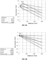
- FIG. 5 shows how the size of the 2D beam steering module can be reduced (in terms of reduction of the lens focal length f, its diameter D lens , and the fiber spacing ⁇ y ), by increasing the defocusing parameter p .
- the current invention can be extended to an AWGR with a larger port count.
- FIG. 6 with e.g.
- f 49.9 mm
- fiber spacing ⁇ y 1.69 mm
- lens diameter D lens 3.11 cm.
- the coverage area can thus be further increased to 1.4 ⁇ 1.4 m 2 .
- the current invention provides ease of assembly and improved stability as the wavelength-dependent functions are done by an integrated optical circuit.
- the 2D beam steering by the alternative module is slightly different from the steering by the two cross-aligned diffraction gratings module as described in US Patent 9,246,589 .
- the steered beam follows discrete steps in both the two angular directions when the wavelength is varied, whereas in the latter one the steered beam is continuous in one angular direction, but takes discrete steps in the orthogonal angular direction.
- full coverage of the target area can be achieved with either module.
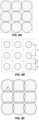
- Another advantage of the defocusing approach is a better fill factor of the covered area.
- the spots will exactly touch each other in the image plane (see FIG. 8A , where the e -2 intensity contours of the Gaussian spot footprints are shown).
- M 196 ports.
- a compact and stable 2D optical beam steering module can be achieved by the proposed concept based on a high fiber-port count optically integrated AWGR followed by a lens including proper defocusing of the 2D fiber matrix.
Landscapes
- Physics & Mathematics (AREA)
- General Physics & Mathematics (AREA)
- Optics & Photonics (AREA)
- Nonlinear Science (AREA)
- Engineering & Computer Science (AREA)
- Microelectronics & Electronic Packaging (AREA)
- Optical Couplings Of Light Guides (AREA)
Claims (2)
- Optische Strahlsteuerungsvorrichtung, die Folgendes umfasst:a) nur eine optische Faser, die mehrere optische Eingangssignale überträgt, wobei jedes dieser optischen Eingangssignale eine eindeutige Wellenlänge aufweist;b) einen Arrayed Waveguide Grating Router, AWGR, mit mehreren Ausgangsfasern,
wobei die optische Eingangsfaser mit dem AWGR verbunden ist, wobei die distalen Enden der mehreren Ausgangsfasern in einem zweidimensionalen Faser-Aarray angeordnet sind, wobei die mehreren optischen Eingangssignale durch den AWGR gemäß jeder der eindeutigen Wellenlänge zu einer eindeutigen AWGR-Ausgangsfaser in dem zweidimensionalen Faser-Array geleitet werden; undc) eine Linse, wobei die distalen Enden der Ausgangsfasern in der Nähe einer Brennebene der Linse angeordnet sind, wobei für jede eindeutige Position jedes distalen Endes der Ausgangsfasern in Bezug auf die Linse jedes optische Eingangssignal unter einem eindeutigen Winkel als ein von der Linse emittierter Ausgangsstrahl gelenkt wird, wobei eine Änderung der Wellenlänge des optischen Eingangssignals die Ausgangsstrahlwinkel für eine zweidimensionale Strahlsteuerung ändert;dadurch gekennzeichnet, dass:
die Ausgangsfaserenden etwas näher an der Hauptebene der Linse als an der Brennebene der Linse positioniert sind, sodass ein Profil des Ausgangsstrahls einen divergierenden Strahl umfasst. - Optische Strahlsteuerungsvorrichtung nach Anspruch 1, wobei das zweidimensionale Faser-Array so konfiguriert ist, dass es mit diskreten Schritten in beiden zweidimensionalen Winkelrichtungen abtastet, wenn die Wellenlänge des optischen Eingangssignals verändert wird.
Applications Claiming Priority (2)
| Application Number | Priority Date | Filing Date | Title |
|---|---|---|---|
| US201662427646P | 2016-11-29 | 2016-11-29 | |
| PCT/EP2017/080716 WO2018099927A1 (en) | 2016-11-29 | 2017-11-28 | Two-dimensional optical beam steering module |
Publications (2)
| Publication Number | Publication Date |
|---|---|
| EP3548943A1 EP3548943A1 (de) | 2019-10-09 |
| EP3548943B1 true EP3548943B1 (de) | 2025-06-25 |
Family
ID=60480324
Family Applications (1)
| Application Number | Title | Priority Date | Filing Date |
|---|---|---|---|
| EP17804903.7A Active EP3548943B1 (de) | 2016-11-29 | 2017-11-28 | Zweidimensionales optisches strahllenkungsmodul |
Country Status (5)
| Country | Link |
|---|---|
| US (1) | US11668876B2 (de) |
| EP (1) | EP3548943B1 (de) |
| CN (1) | CN110178060A (de) |
| ES (1) | ES3041108T3 (de) |
| WO (1) | WO2018099927A1 (de) |
Families Citing this family (2)
| Publication number | Priority date | Publication date | Assignee | Title |
|---|---|---|---|---|
| CN112751616A (zh) * | 2020-12-23 | 2021-05-04 | 杭州电子科技大学 | 一种光无线通信系统 |
| CN119582953B (zh) * | 2024-11-21 | 2025-10-03 | 西南交通大学 | 面向移动目标的LiFi通信系统二维波束扫描与照明光源一体化设计方法 |
Citations (1)
| Publication number | Priority date | Publication date | Assignee | Title |
|---|---|---|---|---|
| US20080138077A1 (en) * | 2004-10-26 | 2008-06-12 | Stephen Stretton | Diverging Beam Optical Communication System |
Family Cites Families (9)
| Publication number | Priority date | Publication date | Assignee | Title |
|---|---|---|---|---|
| CN1093268C (zh) | 1998-09-23 | 2002-10-23 | 西安邮电学院 | 一种波分复用的方法及其装置 |
| CN1217506C (zh) * | 2002-02-05 | 2005-08-31 | 亚太优势微系统股份有限公司 | 多波长光讯号处理装置及其制作方法 |
| WO2003098961A2 (en) * | 2002-05-20 | 2003-11-27 | Metconnex Canada Inc. | Wavelength selective switch |
| CN1217207C (zh) | 2003-09-27 | 2005-08-31 | 浙江大学 | 基于二维分布阵列波导光栅的光波分复用器/解复用器 |
| JP4939341B2 (ja) * | 2007-08-23 | 2012-05-23 | 日本電信電話株式会社 | 光信号処理装置 |
| JP5730526B2 (ja) * | 2010-10-07 | 2015-06-10 | 古河電気工業株式会社 | 光スイッチ |
| US9246589B2 (en) | 2012-01-20 | 2016-01-26 | Technische Universiteit Eindhoven | Two-dimensional optical beam steering module |
| AU2013274359B2 (en) * | 2012-06-11 | 2017-05-25 | Magic Leap, Inc. | Multiple depth plane three-dimensional display using a wave guide reflector array projector |
| CN103759668B (zh) * | 2014-01-02 | 2016-08-17 | 南京理工大学 | 基于光纤阵列型空间点源阵列发生器的倾斜波面干涉系统 |
-
2017
- 2017-11-28 EP EP17804903.7A patent/EP3548943B1/de active Active
- 2017-11-28 ES ES17804903T patent/ES3041108T3/es active Active
- 2017-11-28 US US16/464,358 patent/US11668876B2/en active Active
- 2017-11-28 WO PCT/EP2017/080716 patent/WO2018099927A1/en not_active Ceased
- 2017-11-28 CN CN201780073975.9A patent/CN110178060A/zh active Pending
Patent Citations (1)
| Publication number | Priority date | Publication date | Assignee | Title |
|---|---|---|---|---|
| US20080138077A1 (en) * | 2004-10-26 | 2008-06-12 | Stephen Stretton | Diverging Beam Optical Communication System |
Non-Patent Citations (1)
| Title |
|---|
| KHALID A M ET AL: "10 Gbps indoor optical wireless communication employing 2D passive beam steering based on arrayed waveguide gratings", 2016 IEEE PHOTONICS SOCIETY SUMMER TOPICAL MEETING SERIES (SUM), IEEE, 11 July 2016 (2016-07-11), pages 134 - 135, XP032949049, DOI: 10.1109/PHOSST.2016.7548768 * |
Also Published As
| Publication number | Publication date |
|---|---|
| US20210109286A1 (en) | 2021-04-15 |
| ES3041108T3 (en) | 2025-11-07 |
| WO2018099927A1 (en) | 2018-06-07 |
| US11668876B2 (en) | 2023-06-06 |
| CN110178060A (zh) | 2019-08-27 |
| EP3548943A1 (de) | 2019-10-09 |
Similar Documents
| Publication | Publication Date | Title |
|---|---|---|
| Koonen et al. | High-capacity optical wireless communication using two-dimensional IR beam steering | |
| Abumarshoud et al. | LiFi through reconfigurable intelligent surfaces: A new frontier for 6G? | |
| US20030090765A1 (en) | Free-space optical communication system | |
| US20040120717A1 (en) | Extended source free-space optical communication system | |
| Singh et al. | Design and characterisation of terabit/s capable compact localisation and beam-steering terminals for fiber-wireless-fiber links | |
| US9246589B2 (en) | Two-dimensional optical beam steering module | |
| US6807372B1 (en) | Integrated spectral encoder/decoder for optical CDMA communication system | |
| Koonen et al. | Reconfigurable free-space optical indoor network using multiple pencil beam steering | |
| Oh et al. | 42.8 Gbit/s indoor optical wireless communication with 2-dimensional optical beam-steering | |
| EP3548943B1 (de) | Zweidimensionales optisches strahllenkungsmodul | |
| Oh et al. | 10 Gbps all-optical full-duplex indoor optical wireless communication with wavelength reuse | |
| Sun et al. | Fiber-enabled optical wireless communications with full beam coverage | |
| Koonen et al. | Indoor ultra-high capacity optical wireless communication using steerable infrared beams | |
| Khalid et al. | 10 Gbps indoor optical wireless communication employing 2D passive beam steering based on arrayed waveguide gratings | |
| KR102817323B1 (ko) | 다중입출력 자유공간 무선 광통신 장치 및 방법 | |
| US10374720B2 (en) | Light guide arrangement for a mobile communications device for optical data transmission, mobile communications device and method for optical data transmission | |
| EP2916388B1 (de) | Gruppenantenne, konfigurationsverfahren und kommunikationssystem | |
| Liang et al. | Transparent optical wireless hubs using wavelength space division multiplexing | |
| KR102329109B1 (ko) | 무선 광통신 방향 분할 역다중화가 가능한 포토닉 위상배열 기반 수신기 | |
| WO2023244115A1 (en) | Bi-directional all-optical wireless communication system with autonomous optical beam steering | |
| US7590352B2 (en) | Access method for data packet networks | |
| US6456754B1 (en) | WDM transmitter and receiver | |
| Zakrzewski | Optical RRH working in an all-optical fronthaul network | |
| CN111147147B (zh) | 一种基于相位阵列的无线通信系统及方法 | |
| Khalid et al. | Real time 10Gb-Ethernet transmission over 2D indoor passive beam steered optical wireless system based on high port arrayed waveguide gratings |
Legal Events
| Date | Code | Title | Description |
|---|---|---|---|
| STAA | Information on the status of an ep patent application or granted ep patent |
Free format text: STATUS: UNKNOWN |
|
| STAA | Information on the status of an ep patent application or granted ep patent |
Free format text: STATUS: THE INTERNATIONAL PUBLICATION HAS BEEN MADE |
|
| PUAI | Public reference made under article 153(3) epc to a published international application that has entered the european phase |
Free format text: ORIGINAL CODE: 0009012 |
|
| STAA | Information on the status of an ep patent application or granted ep patent |
Free format text: STATUS: REQUEST FOR EXAMINATION WAS MADE |
|
| 17P | Request for examination filed |
Effective date: 20190618 |
|
| AK | Designated contracting states |
Kind code of ref document: A1 Designated state(s): AL AT BE BG CH CY CZ DE DK EE ES FI FR GB GR HR HU IE IS IT LI LT LU LV MC MK MT NL NO PL PT RO RS SE SI SK SM TR |
|
| AX | Request for extension of the european patent |
Extension state: BA ME |
|
| DAV | Request for validation of the european patent (deleted) | ||
| DAX | Request for extension of the european patent (deleted) | ||
| STAA | Information on the status of an ep patent application or granted ep patent |
Free format text: STATUS: EXAMINATION IS IN PROGRESS |
|
| 17Q | First examination report despatched |
Effective date: 20220421 |
|
| P01 | Opt-out of the competence of the unified patent court (upc) registered |
Effective date: 20230731 |
|
| GRAP | Despatch of communication of intention to grant a patent |
Free format text: ORIGINAL CODE: EPIDOSNIGR1 |
|
| STAA | Information on the status of an ep patent application or granted ep patent |
Free format text: STATUS: GRANT OF PATENT IS INTENDED |
|
| INTG | Intention to grant announced |
Effective date: 20241030 |
|
| GRAS | Grant fee paid |
Free format text: ORIGINAL CODE: EPIDOSNIGR3 |
|
| GRAA | (expected) grant |
Free format text: ORIGINAL CODE: 0009210 |
|
| STAA | Information on the status of an ep patent application or granted ep patent |
Free format text: STATUS: THE PATENT HAS BEEN GRANTED |
|
| AK | Designated contracting states |
Kind code of ref document: B1 Designated state(s): AL AT BE BG CH CY CZ DE DK EE ES FI FR GB GR HR HU IE IS IT LI LT LU LV MC MK MT NL NO PL PT RO RS SE SI SK SM TR |
|
| REG | Reference to a national code |
Ref country code: GB Ref legal event code: FG4D |
|
| REG | Reference to a national code |
Ref country code: CH Ref legal event code: EP |
|
| REG | Reference to a national code |
Ref country code: CH Ref legal event code: EP |
|
| REG | Reference to a national code |
Ref country code: IE Ref legal event code: FG4D |
|
| REG | Reference to a national code |
Ref country code: DE Ref legal event code: R096 Ref document number: 602017090152 Country of ref document: DE |
|
| REG | Reference to a national code |
Ref country code: SE Ref legal event code: TRGR |
|
| PG25 | Lapsed in a contracting state [announced via postgrant information from national office to epo] |
Ref country code: FI Free format text: LAPSE BECAUSE OF FAILURE TO SUBMIT A TRANSLATION OF THE DESCRIPTION OR TO PAY THE FEE WITHIN THE PRESCRIBED TIME-LIMIT Effective date: 20250625 |
|
| REG | Reference to a national code |
Ref country code: LT Ref legal event code: MG9D |
|
| PG25 | Lapsed in a contracting state [announced via postgrant information from national office to epo] |
Ref country code: GR Free format text: LAPSE BECAUSE OF FAILURE TO SUBMIT A TRANSLATION OF THE DESCRIPTION OR TO PAY THE FEE WITHIN THE PRESCRIBED TIME-LIMIT Effective date: 20250926 Ref country code: NO Free format text: LAPSE BECAUSE OF FAILURE TO SUBMIT A TRANSLATION OF THE DESCRIPTION OR TO PAY THE FEE WITHIN THE PRESCRIBED TIME-LIMIT Effective date: 20250925 |
|
| PG25 | Lapsed in a contracting state [announced via postgrant information from national office to epo] |
Ref country code: BG Free format text: LAPSE BECAUSE OF FAILURE TO SUBMIT A TRANSLATION OF THE DESCRIPTION OR TO PAY THE FEE WITHIN THE PRESCRIBED TIME-LIMIT Effective date: 20250625 |
|
| PG25 | Lapsed in a contracting state [announced via postgrant information from national office to epo] |
Ref country code: HR Free format text: LAPSE BECAUSE OF FAILURE TO SUBMIT A TRANSLATION OF THE DESCRIPTION OR TO PAY THE FEE WITHIN THE PRESCRIBED TIME-LIMIT Effective date: 20250625 |
|
| PG25 | Lapsed in a contracting state [announced via postgrant information from national office to epo] |
Ref country code: RS Free format text: LAPSE BECAUSE OF FAILURE TO SUBMIT A TRANSLATION OF THE DESCRIPTION OR TO PAY THE FEE WITHIN THE PRESCRIBED TIME-LIMIT Effective date: 20250925 |
|
| PG25 | Lapsed in a contracting state [announced via postgrant information from national office to epo] |
Ref country code: LV Free format text: LAPSE BECAUSE OF FAILURE TO SUBMIT A TRANSLATION OF THE DESCRIPTION OR TO PAY THE FEE WITHIN THE PRESCRIBED TIME-LIMIT Effective date: 20250625 |
|
| REG | Reference to a national code |
Ref country code: NL Ref legal event code: MP Effective date: 20250625 |
|
| REG | Reference to a national code |
Ref country code: ES Ref legal event code: FG2A Ref document number: 3041108 Country of ref document: ES Kind code of ref document: T3 Effective date: 20251107 |
|
| PG25 | Lapsed in a contracting state [announced via postgrant information from national office to epo] |
Ref country code: NL Free format text: LAPSE BECAUSE OF FAILURE TO SUBMIT A TRANSLATION OF THE DESCRIPTION OR TO PAY THE FEE WITHIN THE PRESCRIBED TIME-LIMIT Effective date: 20250625 |
|
| PG25 | Lapsed in a contracting state [announced via postgrant information from national office to epo] |
Ref country code: PT Free format text: LAPSE BECAUSE OF FAILURE TO SUBMIT A TRANSLATION OF THE DESCRIPTION OR TO PAY THE FEE WITHIN THE PRESCRIBED TIME-LIMIT Effective date: 20251027 |
|
| REG | Reference to a national code |
Ref country code: AT Ref legal event code: MK05 Ref document number: 1807035 Country of ref document: AT Kind code of ref document: T Effective date: 20250625 |
|
| PG25 | Lapsed in a contracting state [announced via postgrant information from national office to epo] |
Ref country code: IS Free format text: LAPSE BECAUSE OF FAILURE TO SUBMIT A TRANSLATION OF THE DESCRIPTION OR TO PAY THE FEE WITHIN THE PRESCRIBED TIME-LIMIT Effective date: 20251025 |
|
| PG25 | Lapsed in a contracting state [announced via postgrant information from national office to epo] |
Ref country code: AT Free format text: LAPSE BECAUSE OF FAILURE TO SUBMIT A TRANSLATION OF THE DESCRIPTION OR TO PAY THE FEE WITHIN THE PRESCRIBED TIME-LIMIT Effective date: 20250625 Ref country code: SM Free format text: LAPSE BECAUSE OF FAILURE TO SUBMIT A TRANSLATION OF THE DESCRIPTION OR TO PAY THE FEE WITHIN THE PRESCRIBED TIME-LIMIT Effective date: 20250625 |
|
| PGFP | Annual fee paid to national office [announced via postgrant information from national office to epo] |
Ref country code: FR Payment date: 20251229 Year of fee payment: 9 |
|
| PG25 | Lapsed in a contracting state [announced via postgrant information from national office to epo] |
Ref country code: CZ Free format text: LAPSE BECAUSE OF FAILURE TO SUBMIT A TRANSLATION OF THE DESCRIPTION OR TO PAY THE FEE WITHIN THE PRESCRIBED TIME-LIMIT Effective date: 20250625 |
|
| PG25 | Lapsed in a contracting state [announced via postgrant information from national office to epo] |
Ref country code: PL Free format text: LAPSE BECAUSE OF FAILURE TO SUBMIT A TRANSLATION OF THE DESCRIPTION OR TO PAY THE FEE WITHIN THE PRESCRIBED TIME-LIMIT Effective date: 20250625 |
|
| PG25 | Lapsed in a contracting state [announced via postgrant information from national office to epo] |
Ref country code: EE Free format text: LAPSE BECAUSE OF FAILURE TO SUBMIT A TRANSLATION OF THE DESCRIPTION OR TO PAY THE FEE WITHIN THE PRESCRIBED TIME-LIMIT Effective date: 20250625 |
|
| PG25 | Lapsed in a contracting state [announced via postgrant information from national office to epo] |
Ref country code: SK Free format text: LAPSE BECAUSE OF FAILURE TO SUBMIT A TRANSLATION OF THE DESCRIPTION OR TO PAY THE FEE WITHIN THE PRESCRIBED TIME-LIMIT Effective date: 20250625 |
|
| PG25 | Lapsed in a contracting state [announced via postgrant information from national office to epo] |
Ref country code: RO Free format text: LAPSE BECAUSE OF FAILURE TO SUBMIT A TRANSLATION OF THE DESCRIPTION OR TO PAY THE FEE WITHIN THE PRESCRIBED TIME-LIMIT Effective date: 20250625 |
|
| PGFP | Annual fee paid to national office [announced via postgrant information from national office to epo] |
Ref country code: SE Payment date: 20260218 Year of fee payment: 9 |
|
| PGFP | Annual fee paid to national office [announced via postgrant information from national office to epo] |
Ref country code: GB Payment date: 20260126 Year of fee payment: 9 |
|
| PGFP | Annual fee paid to national office [announced via postgrant information from national office to epo] |
Ref country code: ES Payment date: 20260219 Year of fee payment: 9 |
|
| PG25 | Lapsed in a contracting state [announced via postgrant information from national office to epo] |
Ref country code: DK Free format text: LAPSE BECAUSE OF FAILURE TO SUBMIT A TRANSLATION OF THE DESCRIPTION OR TO PAY THE FEE WITHIN THE PRESCRIBED TIME-LIMIT Effective date: 20250625 |
|
| PG25 | Lapsed in a contracting state [announced via postgrant information from national office to epo] |
Ref country code: IT Free format text: LAPSE BECAUSE OF FAILURE TO SUBMIT A TRANSLATION OF THE DESCRIPTION OR TO PAY THE FEE WITHIN THE PRESCRIBED TIME-LIMIT Effective date: 20250625 |
|
| PLBE | No opposition filed within time limit |
Free format text: ORIGINAL CODE: 0009261 |
|
| STAA | Information on the status of an ep patent application or granted ep patent |
Free format text: STATUS: NO OPPOSITION FILED WITHIN TIME LIMIT |