EP4459130A1 - Verfahren zur bearbeitung von rippen oder nuten an einer welle für luft- oder gaslager eines verdichters - Google Patents
Verfahren zur bearbeitung von rippen oder nuten an einer welle für luft- oder gaslager eines verdichters Download PDFInfo
- Publication number
- EP4459130A1 EP4459130A1 EP24169647.5A EP24169647A EP4459130A1 EP 4459130 A1 EP4459130 A1 EP 4459130A1 EP 24169647 A EP24169647 A EP 24169647A EP 4459130 A1 EP4459130 A1 EP 4459130A1
- Authority
- EP
- European Patent Office
- Prior art keywords
- shaft
- machining
- grooves
- ribs
- axial bearing
- Prior art date
- Legal status (The legal status is an assumption and is not a legal conclusion. Google has not performed a legal analysis and makes no representation as to the accuracy of the status listed.)
- Pending
Links
Images

Classifications
-
- F—MECHANICAL ENGINEERING; LIGHTING; HEATING; WEAPONS; BLASTING
- F04—POSITIVE - DISPLACEMENT MACHINES FOR LIQUIDS; PUMPS FOR LIQUIDS OR ELASTIC FLUIDS
- F04D—NON-POSITIVE-DISPLACEMENT PUMPS
- F04D29/00—Details, component parts, or accessories
- F04D29/05—Shafts or bearings, or assemblies thereof, specially adapted for elastic fluid pumps
- F04D29/056—Bearings
- F04D29/057—Bearings hydrostatic; hydrodynamic
-
- F—MECHANICAL ENGINEERING; LIGHTING; HEATING; WEAPONS; BLASTING
- F04—POSITIVE - DISPLACEMENT MACHINES FOR LIQUIDS; PUMPS FOR LIQUIDS OR ELASTIC FLUIDS
- F04D—NON-POSITIVE-DISPLACEMENT PUMPS
- F04D29/00—Details, component parts, or accessories
- F04D29/05—Shafts or bearings, or assemblies thereof, specially adapted for elastic fluid pumps
- F04D29/053—Shafts
-
- B—PERFORMING OPERATIONS; TRANSPORTING
- B23—MACHINE TOOLS; METAL-WORKING NOT OTHERWISE PROVIDED FOR
- B23C—MILLING
- B23C3/00—Milling particular work; Special milling operations; Machines therefor
- B23C3/28—Grooving workpieces
- B23C3/34—Milling grooves of other forms, e.g. circumferential
-
- B—PERFORMING OPERATIONS; TRANSPORTING
- B23—MACHINE TOOLS; METAL-WORKING NOT OTHERWISE PROVIDED FOR
- B23B—TURNING; BORING
- B23B5/00—Turning-machines or devices specially adapted for particular work; Accessories specially adapted therefor
- B23B5/36—Turning-machines or devices specially adapted for particular work; Accessories specially adapted therefor for turning specially-shaped surfaces by making use of relative movement of the tool and work produced by geometrical mechanisms, i.e. forming-lathes
- B23B5/46—Turning-machines or devices specially adapted for particular work; Accessories specially adapted therefor for turning specially-shaped surfaces by making use of relative movement of the tool and work produced by geometrical mechanisms, i.e. forming-lathes for turning helical or spiral surfaces
- B23B5/48—Turning-machines or devices specially adapted for particular work; Accessories specially adapted therefor for turning specially-shaped surfaces by making use of relative movement of the tool and work produced by geometrical mechanisms, i.e. forming-lathes for turning helical or spiral surfaces for cutting grooves, e.g. oil grooves of helicoidal shape
-
- B—PERFORMING OPERATIONS; TRANSPORTING
- B23—MACHINE TOOLS; METAL-WORKING NOT OTHERWISE PROVIDED FOR
- B23B—TURNING; BORING
- B23B1/00—Methods for turning or working essentially requiring the use of turning-machines; Use of auxiliary equipment in connection with such methods
-
- B—PERFORMING OPERATIONS; TRANSPORTING
- B23—MACHINE TOOLS; METAL-WORKING NOT OTHERWISE PROVIDED FOR
- B23B—TURNING; BORING
- B23B29/00—Holders for non-rotary cutting tools; Boring bars or boring heads; Accessories for tool holders
- B23B29/04—Tool holders for a single cutting tool
- B23B29/12—Special arrangements on tool holders
- B23B29/125—Vibratory toolholders
-
- B—PERFORMING OPERATIONS; TRANSPORTING
- B23—MACHINE TOOLS; METAL-WORKING NOT OTHERWISE PROVIDED FOR
- B23C—MILLING
- B23C3/00—Milling particular work; Special milling operations; Machines therefor
- B23C3/002—Milling elongated workpieces
-
- B—PERFORMING OPERATIONS; TRANSPORTING
- B23—MACHINE TOOLS; METAL-WORKING NOT OTHERWISE PROVIDED FOR
- B23P—METAL-WORKING NOT OTHERWISE PROVIDED FOR; COMBINED OPERATIONS; UNIVERSAL MACHINE TOOLS
- B23P17/00—Metal-working operations, not covered by a single other subclass or another group in this subclass
-
- F—MECHANICAL ENGINEERING; LIGHTING; HEATING; WEAPONS; BLASTING
- F04—POSITIVE - DISPLACEMENT MACHINES FOR LIQUIDS; PUMPS FOR LIQUIDS OR ELASTIC FLUIDS
- F04D—NON-POSITIVE-DISPLACEMENT PUMPS
- F04D17/00—Radial-flow pumps, e.g. centrifugal pumps; Helico-centrifugal pumps
- F04D17/08—Centrifugal pumps
- F04D17/10—Centrifugal pumps for compressing or evacuating
- F04D17/12—Multi-stage pumps
- F04D17/122—Multi-stage pumps the individual rotor discs being, one for each stage, on a common shaft and axially spaced, e.g. conventional centrifugal multi- stage compressors
-
- F—MECHANICAL ENGINEERING; LIGHTING; HEATING; WEAPONS; BLASTING
- F04—POSITIVE - DISPLACEMENT MACHINES FOR LIQUIDS; PUMPS FOR LIQUIDS OR ELASTIC FLUIDS
- F04D—NON-POSITIVE-DISPLACEMENT PUMPS
- F04D25/00—Pumping installations or systems
- F04D25/02—Units comprising pumps and their driving means
- F04D25/06—Units comprising pumps and their driving means the pump being electrically driven
-
- F—MECHANICAL ENGINEERING; LIGHTING; HEATING; WEAPONS; BLASTING
- F04—POSITIVE - DISPLACEMENT MACHINES FOR LIQUIDS; PUMPS FOR LIQUIDS OR ELASTIC FLUIDS
- F04D—NON-POSITIVE-DISPLACEMENT PUMPS
- F04D29/00—Details, component parts, or accessories
- F04D29/05—Shafts or bearings, or assemblies thereof, specially adapted for elastic fluid pumps
- F04D29/051—Axial thrust balancing
- F04D29/0513—Axial thrust balancing hydrostatic; hydrodynamic thrust bearings
-
- F—MECHANICAL ENGINEERING; LIGHTING; HEATING; WEAPONS; BLASTING
- F04—POSITIVE - DISPLACEMENT MACHINES FOR LIQUIDS; PUMPS FOR LIQUIDS OR ELASTIC FLUIDS
- F04D—NON-POSITIVE-DISPLACEMENT PUMPS
- F04D29/00—Details, component parts, or accessories
- F04D29/05—Shafts or bearings, or assemblies thereof, specially adapted for elastic fluid pumps
- F04D29/053—Shafts
- F04D29/054—Arrangements for joining or assembling shafts
-
- F—MECHANICAL ENGINEERING; LIGHTING; HEATING; WEAPONS; BLASTING
- F04—POSITIVE - DISPLACEMENT MACHINES FOR LIQUIDS; PUMPS FOR LIQUIDS OR ELASTIC FLUIDS
- F04D—NON-POSITIVE-DISPLACEMENT PUMPS
- F04D29/00—Details, component parts, or accessories
- F04D29/05—Shafts or bearings, or assemblies thereof, specially adapted for elastic fluid pumps
- F04D29/056—Bearings
-
- F—MECHANICAL ENGINEERING; LIGHTING; HEATING; WEAPONS; BLASTING
- F16—ENGINEERING ELEMENTS AND UNITS; GENERAL MEASURES FOR PRODUCING AND MAINTAINING EFFECTIVE FUNCTIONING OF MACHINES OR INSTALLATIONS; THERMAL INSULATION IN GENERAL
- F16C—SHAFTS; FLEXIBLE SHAFTS; ELEMENTS OR CRANKSHAFT MECHANISMS; ROTARY BODIES OTHER THAN GEARING ELEMENTS; BEARINGS
- F16C17/00—Sliding-contact bearings for exclusively rotary movement
- F16C17/02—Sliding-contact bearings for exclusively rotary movement for radial load only
- F16C17/026—Sliding-contact bearings for exclusively rotary movement for radial load only with helical grooves in the bearing surface to generate hydrodynamic pressure, e.g. herringbone grooves
-
- F—MECHANICAL ENGINEERING; LIGHTING; HEATING; WEAPONS; BLASTING
- F16—ENGINEERING ELEMENTS AND UNITS; GENERAL MEASURES FOR PRODUCING AND MAINTAINING EFFECTIVE FUNCTIONING OF MACHINES OR INSTALLATIONS; THERMAL INSULATION IN GENERAL
- F16C—SHAFTS; FLEXIBLE SHAFTS; ELEMENTS OR CRANKSHAFT MECHANISMS; ROTARY BODIES OTHER THAN GEARING ELEMENTS; BEARINGS
- F16C17/00—Sliding-contact bearings for exclusively rotary movement
- F16C17/04—Sliding-contact bearings for exclusively rotary movement for axial load only
- F16C17/045—Sliding-contact bearings for exclusively rotary movement for axial load only with grooves in the bearing surface to generate hydrodynamic pressure, e.g. spiral groove thrust bearings
-
- F—MECHANICAL ENGINEERING; LIGHTING; HEATING; WEAPONS; BLASTING
- F16—ENGINEERING ELEMENTS AND UNITS; GENERAL MEASURES FOR PRODUCING AND MAINTAINING EFFECTIVE FUNCTIONING OF MACHINES OR INSTALLATIONS; THERMAL INSULATION IN GENERAL
- F16C—SHAFTS; FLEXIBLE SHAFTS; ELEMENTS OR CRANKSHAFT MECHANISMS; ROTARY BODIES OTHER THAN GEARING ELEMENTS; BEARINGS
- F16C3/00—Shafts; Axles; Cranks; Eccentrics
- F16C3/02—Shafts; Axles
-
- F—MECHANICAL ENGINEERING; LIGHTING; HEATING; WEAPONS; BLASTING
- F16—ENGINEERING ELEMENTS AND UNITS; GENERAL MEASURES FOR PRODUCING AND MAINTAINING EFFECTIVE FUNCTIONING OF MACHINES OR INSTALLATIONS; THERMAL INSULATION IN GENERAL
- F16C—SHAFTS; FLEXIBLE SHAFTS; ELEMENTS OR CRANKSHAFT MECHANISMS; ROTARY BODIES OTHER THAN GEARING ELEMENTS; BEARINGS
- F16C32/00—Bearings not otherwise provided for
- F16C32/06—Bearings not otherwise provided for with moving member supported by a fluid cushion formed, at least to a large extent, otherwise than by movement of the shaft, e.g. hydrostatic air-cushion bearings
- F16C32/0681—Construction or mounting aspects of hydrostatic bearings, for exclusively rotary movement, related to the direction of load
- F16C32/0692—Construction or mounting aspects of hydrostatic bearings, for exclusively rotary movement, related to the direction of load for axial load only
-
- B—PERFORMING OPERATIONS; TRANSPORTING
- B23—MACHINE TOOLS; METAL-WORKING NOT OTHERWISE PROVIDED FOR
- B23B—TURNING; BORING
- B23B2215/00—Details of workpieces
- B23B2215/12—Bearing races
-
- B—PERFORMING OPERATIONS; TRANSPORTING
- B23—MACHINE TOOLS; METAL-WORKING NOT OTHERWISE PROVIDED FOR
- B23B—TURNING; BORING
- B23B2220/00—Details of turning, boring or drilling processes
- B23B2220/12—Grooving
-
- B—PERFORMING OPERATIONS; TRANSPORTING
- B23—MACHINE TOOLS; METAL-WORKING NOT OTHERWISE PROVIDED FOR
- B23B—TURNING; BORING
- B23B2222/00—Materials of tools or workpieces composed of metals, alloys or metal matrices
- B23B2222/28—Details of hard metal, i.e. cemented carbide
-
- B—PERFORMING OPERATIONS; TRANSPORTING
- B23—MACHINE TOOLS; METAL-WORKING NOT OTHERWISE PROVIDED FOR
- B23B—TURNING; BORING
- B23B2226/00—Materials of tools or workpieces not comprising a metal
- B23B2226/18—Ceramic
-
- B—PERFORMING OPERATIONS; TRANSPORTING
- B23—MACHINE TOOLS; METAL-WORKING NOT OTHERWISE PROVIDED FOR
- B23B—TURNING; BORING
- B23B2226/00—Materials of tools or workpieces not comprising a metal
- B23B2226/31—Diamond
-
- B—PERFORMING OPERATIONS; TRANSPORTING
- B23—MACHINE TOOLS; METAL-WORKING NOT OTHERWISE PROVIDED FOR
- B23B—TURNING; BORING
- B23B2260/00—Details of constructional elements
- B23B2260/072—Grooves
- B23B2260/0725—Spiral
-
- F—MECHANICAL ENGINEERING; LIGHTING; HEATING; WEAPONS; BLASTING
- F04—POSITIVE - DISPLACEMENT MACHINES FOR LIQUIDS; PUMPS FOR LIQUIDS OR ELASTIC FLUIDS
- F04D—NON-POSITIVE-DISPLACEMENT PUMPS
- F04D29/00—Details, component parts, or accessories
- F04D29/40—Casings; Connections of working fluid
- F04D29/42—Casings; Connections of working fluid for radial or helico-centrifugal pumps
- F04D29/4206—Casings; Connections of working fluid for radial or helico-centrifugal pumps especially adapted for elastic fluid pumps
-
- F—MECHANICAL ENGINEERING; LIGHTING; HEATING; WEAPONS; BLASTING
- F05—INDEXING SCHEMES RELATING TO ENGINES OR PUMPS IN VARIOUS SUBCLASSES OF CLASSES F01-F04
- F05D—INDEXING SCHEME FOR ASPECTS RELATING TO NON-POSITIVE-DISPLACEMENT MACHINES OR ENGINES, GAS-TURBINES OR JET-PROPULSION PLANTS
- F05D2230/00—Manufacture
- F05D2230/10—Manufacture by removing material
- F05D2230/14—Micromachining
-
- F—MECHANICAL ENGINEERING; LIGHTING; HEATING; WEAPONS; BLASTING
- F16—ENGINEERING ELEMENTS AND UNITS; GENERAL MEASURES FOR PRODUCING AND MAINTAINING EFFECTIVE FUNCTIONING OF MACHINES OR INSTALLATIONS; THERMAL INSULATION IN GENERAL
- F16C—SHAFTS; FLEXIBLE SHAFTS; ELEMENTS OR CRANKSHAFT MECHANISMS; ROTARY BODIES OTHER THAN GEARING ELEMENTS; BEARINGS
- F16C2220/00—Shaping
- F16C2220/60—Shaping by removing material, e.g. machining
- F16C2220/62—Shaping by removing material, e.g. machining by turning, boring, drilling
-
- F—MECHANICAL ENGINEERING; LIGHTING; HEATING; WEAPONS; BLASTING
- F16—ENGINEERING ELEMENTS AND UNITS; GENERAL MEASURES FOR PRODUCING AND MAINTAINING EFFECTIVE FUNCTIONING OF MACHINES OR INSTALLATIONS; THERMAL INSULATION IN GENERAL
- F16C—SHAFTS; FLEXIBLE SHAFTS; ELEMENTS OR CRANKSHAFT MECHANISMS; ROTARY BODIES OTHER THAN GEARING ELEMENTS; BEARINGS
- F16C2360/00—Engines or pumps
- F16C2360/23—Gas turbine engines
Definitions
- the invention relates to a method for machining ribs or grooves on a shaft for air or gas bearings of a high-speed centrifugal fluid compressor.
- the compressor is a two-stage compressor, and comprises a casing with a fluid inlet and a compressed fluid outlet and encloses a shaft rotatably mounted about a longitudinal axis.
- a first compressor wheel and a second compressor wheel are mounted back-to-back on the shaft, the first compressor wheel constituting a first compression stage and the second compressor wheel constituting a second compression stage.
- the centrifugal compressor further comprises a motor, preferably a synchronous electric motor, positioned between the first compressor wheel and the second compressor wheel and arranged to rotate the shaft.
- At least one air or gas axial bearing forms a part of the shaft and is disposed at one end of the shaft.
- a front air or gas radial bearing can be mounted on a first end of the shaft and a rear air or gas radial bearing can be mounted on a second end of the shaft.
- Fluid compressors are typically referred to as turbocompressors or centrifugal compressors. They comprise a stator and a rotor forming a permanent magnet synchronous motor (brushless motor). They can reach very high speeds, such as 100,000 to 500,000 rpm.
- the motor drives the compressor wheels at high speed, at which the compressor wheels compress the fluid.
- the fluid can be air, a gas, a refrigerant or any other suitable fluid. By using two compressor wheels, the fluid is compressed twice as much.
- compressors can be used, for example, in a mobile HVAC (heating, ventilation and air conditioning) system with a refrigerant gas, such as in electric, hybrid or hydrogen-powered vehicles. These compressors can also be used in a stationary system with a refrigerant gas, such as a heat pump.
- a mobile HVAC heating, ventilation and air conditioning
- refrigerant gas such as in electric, hybrid or hydrogen-powered vehicles.
- compressors can also be used in a stationary system with a refrigerant gas, such as a heat pump.
- These compressors typically comprise a first circuit for circulating the fluid to be compressed and a second circuit for circulating a cooling liquid used to cool the compressor, and more particularly the motor and the air or gas bearings supporting the motor shaft on the one hand, and the electronic components on the other. More specifically, rotating the motor at high speed causes it to heat up considerably, so much so that the compressor components need to be cooled to prevent damage thereto.
- These circuits are typically provided inside the compressor itself, at least as far as the cooling circuit is concerned. There is no provision to facilitate the flow of the cooling gas or air during the operation of the compressor, in particular at high speeds, which constitutes a drawback.
- the air or gas bearings supporting the rotor shaft are not designed to support the rotor shaft without friction, which leads to significant heat generation when the rotor is rotating at a high speed, which constitutes another drawback.
- grooves or ribs are known to be made on the air or gas bearings for air or gas flow, and to create pressure and cooling.
- the grooves are produced without any specific arrangement by laser machining, which constitutes a drawback because the machining time is too long and thus the costs thereof are too high.
- One purpose of the invention is to overcome the various drawbacks mentioned hereinabove by means of a method for rapidly producing grooves or ribs on a rotor shaft for air or gas bearings, including an air or gas axial bearing which forms part of the shaft.
- Said grooves or ribs on the shaft are arranged in such a way as to overcome gravity when the shaft of the compressor rotates at high speed in each bearing and to allow the rotating rotor shaft to be held without mechanical contact on an air or gas current in the radial bearings and thus virtually frictionlessly.
- the present invention relates to a method for machining ribs or grooves on a shaft intended to be rotated about a longitudinal axis of a centrifugal compressor, and/or on an air or gas axial bearing forming part of the shaft, which method comprises the features of independent claim 1.
- One advantage of the method for machining ribs or grooves on the shaft and/or the axial bearing of the workpiece shaft of the compressor in a machining unit is that all the ribs or grooves are obtained at once on a workpiece portion of the shaft driven in rotation, by a machining tool which moves back and forth from the beginning to the end of the workpiece portion of the shaft.
- the reciprocating motions of the machining tool are synchronised with the sinusoidal program set up in the machining unit, as well as with the desired arrangement of the ribs or grooves to be produced on the portion of the shaft.
- One advantage of the method for machining ribs or grooves on the axial bearing of the workpiece shaft of the compressor in a machining unit is that all the ribs or grooves are obtained on one or two faces of the disc of the axial bearing of the shaft driven rotatably.
- the shaft or the tool holder carrying the machining tool is also displaced in a longitudinal machining direction while the machining tool carries out the reciprocating motions.
- the reciprocating motions of the tool are compared to a piezoelectric oscillator where the oscillation frequency can be varied to speed up or slow down the reciprocating motions of the tool according to how the machining unit was programmed to obtain said desired ribs or grooves.
- the tool is in the machining position and in contact with the shaft or the axial bearing of the shaft at one time and not in contact with the shaft or the axial bearing of the shaft at another time.
- the workpiece shaft is attached to a rotor structure of an electric motor driving it in rotation, and at least one air or gas axial bearing forming part of the shaft and disposed at a first end of the shaft between a compressor wheel and an air or gas radial bearing.
- Ribs or grooves can be produced on one face or preferably on two faces of the disc of the air or gas axial bearing by a specific tool for machining ribs or grooves in the axial bearing. However, the same machining tool can be used to machine the ribs or grooves on portions of the shaft for the radial bearings and on one or two faces of the disc of the air or gas axial bearing.
- One advantage of the method for machining ribs or grooves in a machining unit is that the ribs or grooves are produced very quickly in less than 1 minute on each workpiece portion of the shaft for the air or gas radial bearings and with great precision. The same applies to the grooves or ribs produced on one or two faces of the disc of the air or gas axial bearing driven rotatably.
- the machining tool is harder than the material of the shaft or of the air or gas axial bearing.
- the sinusoidal function therefore makes it possible to achieve synchronisation between the rotation of the shaft and the movement in a longitudinal direction of the machining tool or the shaft.
- the frequency and amplitude of the sinusoidal function are chosen as a function of the geometry of the grooves, the number of grooves, the speed of rotation of the shaft and the speed of the longitudinal displacement.
- the machining unit can be programmed for simultaneous synchronised rotation with the machining tool according to a sinusoidal program or function to obtain a rib or groove arrangement on each workpiece portion of the shaft for each air or gas radial bearing, and for the air or gas axial bearing.
- the shaft rotating at high speed can be held in the compressor in the air or gas radial bearings without mechanical contact.
- the shaft is thus held in each radial bearing with virtually no friction by the pressure of the air or gas passing within the grooves or ribs as a result of the high-speed rotation of the shaft.
- the air or gas pressure in each aerodynamic radial bearing is such that the shaft is no longer in mechanical contact with the static radial bearing, thus avoiding any mechanical friction. It goes without saying that the faster the shaft rotates, the greater the air pressure in the radial bearing, which automatically generates more air or gas friction.
- the grooves or ribs are machined by the machining unit and the machining tool according to a sinusoidal program and the desired arrangement of the grooves or ribs, so as to reverse the orientation of the grooves or ribs on the shaft that is substantially towards the inner half of each static radial bearing placed above said ribs. This generates an air or gas pressure, which can become greater and greater the faster the shaft rotates.
- Such a high-speed centrifugal fluid compressor can rotate at very high speeds without excessive heating due to the production of the ribs or grooves on the air or gas radial bearings.
- a axial bearing is also provided between the first compressor wheel and the first radial bearing.
- Grooves or ribs are made at the periphery in the form of spirals on a front face and a rear face of the disc of the axial bearing. Films of air are generated by the grooves as the shaft rotates to hold the axis in a longitudinally well-centred position.
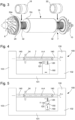
- Fig. 1 shows a cross-section, along the longitudinal axis A-A, of a high-speed centrifugal compressor 1.
- the centrifugal compressor comprises, in a casing 2, a shaft 7 made of tungsten carbide or ceramic, mounted such that it rotates about a longitudinal axis A-A passing through the front face 2b and rear face 2c, a first centrifugal compressor wheel 8 and a second centrifugal compressor wheel 10 mounted back-to-back at each end of the shaft 7, said first compressor wheel 8 constituting a first compression stage and said second compressor wheel 10 constituting a second compression stage.
- the shaft 7 is hollow in this embodiment and encloses a threaded rod 11, to each end whereof one of the compressor wheels 8, 10 is screwed, enabling the compressor wheels to be easily mounted and removed.
- the two compressor wheels 8 and 10 are driven on the same shaft 7, which improves the energy efficiency and avoids the need for a gearbox.
- the rear of the compressor wheels 8 and 10 includes a labyrinth seal to control the pressures in the compressor and balance the axial forces.
- the casing 2 further encloses an electric motor that is preferably synchronous, positioned between the first compressor wheel 8 and the second compressor wheel 10 and arranged to rotate the shaft 7.
- the motor comprises a stator 14 and a rotor structure 16 which interact with one another to form a synchronous electric motor with at least one permanent magnet 16a (brushless motor).
- the stator 14 is formed by a coil 14a and two ferrite elements 14b, mounted such that they are fixed relative to the casing 2.
- the rotor structure 16 comprises one or more permanent magnets 16a made integral with the shaft 7, for example by bonding, and is covered by a titanium lining 16b. Titanium flanges 16c are attached (for example by bonding) to the lateral ends of the lining and ensure that the rotor is resistant to the centrifugal forces at high speeds.
- the shaft 7 is rotatably mounted in the casing 2 about the longitudinal axis A-A thereof by means of at least one front radial bearing 18, one rear radial bearing 22 and one axial bearing 24, which forms an integral part of the shaft 7.
- the centrifugal compressor 1 comprises a front radial bearing support 26 for carrying the front radial bearing 18, and a rear radial bearing support 28 for carrying the rear radial bearing 22, arranged to be positioned around the shaft 7, respectively at the front and rear of the motor.
- a volute 29 is also provided between the rear radial bearing support 28 and the rear cover 3c.
- the volute 29 comprises the orifice leading to the tangential fluid outlet 6, after compression.
- a axial bearing support 30 is also provided to carry the axial bearing 24, arranged to be positioned around the shaft 7, between the first compressor wheel 8 and the front radial bearing support 26. It is clear that the axial bearing could be provided at the rear of the motor.
- the bearings are non-contact, aerodynamic type bearings, in order to generate little friction. They require no lubrication and very little maintenance. More particularly, with reference to Fig. 2a, 2b , 3, 4 and 5 , the axial bearing 24 is an aerodynamic bearing. According to the present invention, it forms part of the shaft 7 as such, that is to say that it is made at the same time and from the same base material as the shaft 7, so as to form one piece with the shaft 7 in the form of a one-piece unit at the end of production.
- This axial bearing is constituted by a disc including, on at least one of the faces thereof, first grooves 24a, preferably spiral-shaped over an annular area at the periphery, arranged to create a film of air.
- the axial bearing 24 comprises preferably spiral-shaped grooves or ribs 24a at the periphery of the disc of the axial bearing 24 on a front face and on a rear face, obtained by a machining process explained below with reference to Fig. 4 and 5 .
- the orientation of the grooves or ribs 24a can be different on the front face to that on the rear face or can be identical.
- the axial bearing 24 with its grooves or ribs 24a keeps the rotating shaft 7 longitudinally centred by generating films of air from the front face and rear face.
- the front radial bearing 18 and the rear radial bearing 22 are aerodynamic bearings, and the shaft 7 has, facing the front radial bearing 18 and rear radial bearing 22, second grooves or ribs 32 arranged to create a film of air or gas when the shaft is rotated in the air or gas radial bearings.
- the first centrifugal compressor wheel 8 and the second centrifugal compressor wheel 10 can still be seen mounted back-to-back at each end of the shaft 7.
- a rotor structure 16 with at least one permanent magnet 16a of an electric motor is mounted or fastened for example on or in a central part of the shaft 7, to drive the shaft rotatably about the longitudinal axis A-A, and an air or gas axial bearing 24 forming part of the shaft 7.
- a front air or gas radial bearing 18 is mounted on a first end of the shaft 7, and a rear air or gas radial bearing 22 is mounted on a second end of the shaft 7, as shown in Fig. 2a .
- the rotor structure 16 with at least one permanent magnet 16a is attached to the shaft 7 in a central position for the electric motor.
- Fig. 3 shows a three-dimensional view of the shaft 7 with the axial bearing 24 at a first end of the shaft 7.
- a first portion of ribs or grooves 32 can be seen with the first radial bearing 18 shown in elevation above the ribs or grooves 32, and a second portion of ribs or grooves 32 with the second radial bearing 22 shown in elevation above these ribs or grooves 32.
- Ribs or grooves 24a are also shown on a face of the disc of the air or gas axial bearing 24 forming part of the shaft 7. Ribs or grooves 24a of a certain depth are produced on an annular area starting from the periphery of the disc and leading towards the centre of the disc.
- the ribs or grooves 24a and the arrangement thereof are programmed, in particular in the machining unit, to activate the machining tool so as to produce all of the ribs or grooves at once, i.e. by moving the tool holder, or the rotating disc in a single machining direction, for example from the periphery of the disc to the bottom of the annular area of the ribs or grooves.
- groove portions are gradually formed by reciprocating motions of the machining tool in synchronism with the machining unit rotating the disc at a given speed according to a sinusoidal program.
- each start of all of the grooves 24a is achieved by the rotation of the disc and the reciprocating motions of the machining tool. This is continuously repeated for the following groove or rib portions continuously from the first groove portion to the end or to the bottom of the annular area.
- the machining time per grooved face of the disc is less than one minute, which is significantly different from a previous machining technique using a laser beam.
- the machining unit is programmed to have a simultaneous synchronised rotation of the shaft 7 with the machining tool according to a sinusoidal program to obtain a determined arrangement of the ribs or grooves 32 on the first workpiece portion of the shaft 7 for the front air or gas radial bearing 18.
- a sinusoidal program to obtain a determined arrangement of the ribs or grooves 32 on the first workpiece portion of the shaft 7 for the front air or gas radial bearing 18.
- the sinusoidal function does indeed achieve synchronisation between the rotation of the shaft 7 and the displacement in a longitudinal direction of the machining tool or of the shaft 7.
- the frequency and amplitude of the sinusoidal function are chosen as a function of the geometry of the grooves 32, the number of grooves 32, the speed of rotation of the shaft and the speed of the longitudinal displacement.
- the ribs or grooves 32 produced on the first portion of the first end of the shaft 7 is programmed in the machining unit.
- the ribs or grooves 32 are each V-shaped, i.e. they include a change of orientation in principle from the middle of the first workpiece portion of the shaft 7. This ensures that the shaft rotating at high speed in the compressor is held without mechanical contact in the air or gas radial bearings. From as low as 6,000 rpm, the air or gas pressure in each aerodynamic radial bearing is such that the shaft is no longer in mechanical contact with the static radial bearing, thus avoiding any mechanical friction.
- the compressor 1 comprises a casing 2, made of aluminium, the top face 2a whereof is closed by a top cover 3a and the front face 2b and rear face 2c whereof are closed by a front cover 3b and a rear cover 3c respectively.
- the side faces 2d of the casing are joined at their base to form a back 2e with a U-shaped cross-section.
- the top cover 3a is positioned on the same side as the electronic components of the compressor. Thus, access to the electronic components integrated in the compressor is easy, which access is provided through the top cover 3a.
- the front and rear covers 3b, 3c are used to reach the interior of the compressor (motor, rotor, bearings, etc.).
- a gasket is interposed between the top face of the casing 2 and the top cover 3a. This gasket protects the electronic components from dust and moisture.
- the casing 2 has an inlet 5 for the fluid to be compressed provided on the front cover 3b and a tangential outlet 6 for the compressed fluid provided on one of the side faces of the casing 2.
- the casing 2 comprises an inner housing extending coaxially to the longitudinal axis A-A from end to end between the front face 2b and the rear face 2c of the casing 2 and receiving the front radial bearing support 26 and the front radial bearing 18, the motor and the rotor structure 16 thereof attached to the shaft 7, the rear radial bearing support 28 and the rear radial bearing 22, the second compressor wheel 10 and the volute 29.
- the inner housing On the front face 2b side, the inner housing is closed by the front cover 3b which integrates the first compressor wheel 8, the axial bearing support 30 and the axial bearing 24.
- the inner housing is closed by the rear cover 3c.
- At least one orifice is advantageously provided, for example the point given the reference 57a, arranged to allow the fluid to be compressed circulating within the channels to enter the motor and circulate between the stator 14 and the rotor structure 16, and at least one orifice, for example the points given the reference 57b, arranged to allow the fluid to be compressed to exit the motor and rejoin said channels after having cooled the motor.
- At least one orifice is advantageously provided, for example the points given the reference 59a in Fig. 1 , arranged to allow the fluid to be compressed circulating within the channels 54 to circulate in the vicinity of the axial bearing 24, the front radial bearing 18 and the rear radial bearing 22, and at least one orifice corresponding, for example, to the same points given the reference 57b, arranged to allow the fluid to be compressed to rejoin said channels 54 after having cooled said axial bearing 24, front radial bearing 18 and rear radial bearing 22.
- the fluid to be compressed passes in the channels 54 through the parts of the compressor located along the longitudinal axis between the first compression stage and the second compression stage to rejoin the second compression stage.
- the fluid to be compressed cools the latter and recovers lost heat from the motor to increase the efficiency thereof before entering the second compression stage.
- the orifices 57a, 57b, 59a allow for a slight deviation of the flow so that the fluid to be compressed also circulates between the stator 14 and the rotor structure 16 and in the bearings in order to cool these elements and recover the heat losses from the motor and the heat losses due to friction in the bearings.
- the centrifugal compressor 1 allows very high rotational speeds to be reached, lying in the range 100,000 rpm to 500,000 rpm. It allows the fluid compressed in the first compression stage to pass substantially through the entire system to recover any waste heat, and in particular waste heat from the motor, bearings and electronic components, in order to increase the efficiency thereof before entering the second compression stage (as the temperature of the fluid to be compressed increases, so does the pressure thereof). Moreover, the use of the only fluid to be compressed to cool the compressor, without the aid of an additional cooling circuit, as well as the arrangement of the electronic components in the compressor for the electronics to be integrated into the casing, results in a very compact compressor.
- the compressor according to the invention thus has a high rotational speed and a high compression ratio while occupying a small volume. For example, a compressor according to the invention has a compression ratio greater than 3, and a power of the order of 4 kW for dimensions L ⁇ W ⁇ H in cm of the order of 14 ⁇ 8 ⁇ 11 for a weight of only 1.6 kg.
- the compressor according to the invention can be used with air or gas to power fuel cells, or any other system that uses compressed air (industrial compressors, medical compressors, ships, etc.).
- the compressor according to the invention can be used in a mobile HVAC (heating, ventilation and air conditioning) system, such as in electric, hybrid or hydrogen-powered vehicles.
- a mobile HVAC heating, ventilation and air conditioning
- the centrifugal compressor can also be used in a stationary system with a refrigerant gas such as a heat pump.
- the centrifugal compressor can also be used with a natural gas.
- Fig. 4 shows a machining unit 100 for producing ribs or grooves on portions of the first end and of the second end of the shaft 7, as well as for producing ribs or grooves on a first face of the disc of the axial bearing 24 forming part of the shaft 7 or also on a second face of the disc of the axial bearing 24 forming part of the shaft 7.
- the machining unit 100 comprises a lathe 130 with two spindles 140 for holding the shaft 7 at both ends of the shaft 7 and for rotating it when machining the ribs or grooves at a determined rotational speed ⁇ .
- a first spindle 140 is located on a first vertical column or wall 102 of the machining unit 100, whereas the second spindle 140 is located on a second vertical column or wall 103 opposite the first vertical column or wall 102.
- the two vertical walls 102, 103 of the machining unit 100 are connected by a base 101 in which is arranged a means for guiding at least one tool holder 160 capable of carrying at least one machining tool 120 or two machining tools 120, 121 or a plurality of other different machining tools.
- the means for guiding the tool holder 160 in the base 101 of the machining unit 100 can be moved in a longitudinal direction A-A on one or two guide rails for example (not shown) in the base 101.
- the tool holder 160 can be moved parallel and preferably horizontally to the shaft 7 so as to place the first machining tool 120 in a machining position as already explained above.
- the first machining tool 120 is oriented perpendicularly to the portion of the shaft 7 so as to be able to machine the ribs or grooves on one of the workpiece portions of the shaft 7. Subsequently, the tool holder 160 is again moved parallel to the shaft 7 towards the second workpiece portion of the shaft.
- a second machining tool 121 can be provided, attached to the same tool holder 160 as the first machining tool 120, or to another tool holder (not shown), but oriented in a direction perpendicular to the direction of the first machining tool.
- This second machining tool 121 can be used to machine the ribs or grooves on at least one face of the disc of the axial bearing 24 forming part of the shaft 7. To do this, the tool holder 160 is moved parallel to the shaft 7 as far as the disc of the axial bearing 24. Once positioned close to the disc, the second machining tool 121 is driven to machine the ribs or grooves on at least one of the faces of the disc of the axial bearing 24.
- the spindles 140 which hold the shaft 7 rotatably, can be moved in a longitudinal machining direction to produce the ribs or grooves.
- the shaft 7 is tubular so that it can be attached and moved in a longitudinal direction.
- the two spindles 140 can have their ends partially inserted into the inner tube of the shaft at both ends of the shaft to hold it locked and rotate it at a set rotational speed ⁇ for machining. It goes without saying that the two spindles 140 with the shaft 7 to be machined can move in a longitudinal direction during the machining operation.
- the machining unit 100 further comprises at least one tool holder 160, which is connected to the structure of the lathe 130. It goes without saying that the actual dimensions of the machining unit 100 are presented smaller than they would be in reality.
- the tool holder 160 carries a first machining tool 120 whose machining head can come into contact with the shaft 7 to machine the grooves or ribs and can be moved back and forth according to how the machining unit 100 is programmed. At least the end of the head of the machining tool 120 can be made of diamond for machining the ribs or grooves on the shaft 7 made of tungsten carbide or ceramic.
- This is carried out so as to have a simultaneous synchronised rotation of the shaft 7 with the first machining tool 120 according to a sinusoidal program to obtain a determined arrangement of the ribs or grooves on the workpiece portions of the shaft 7 for each front or rear air or gas radial bearing.
- the tool holder 160 with the first machining tool 120 can also be jointly moved in a longitudinal machining direction instead of the shaft 7 for machining the ribs or grooves on the shaft.
- the frequency of the reciprocating motions of the first machining tool 120 can also be changed according to how the machining unit 100 is programmed.
- the reciprocating motions of the machining tool are synchronised by sinusoidal programming carried out in the machining unit, as well as to the desired and programmed arrangement of the ribs or grooves to be produced on the portion of the shaft 7 and/or of the disc of the axial bearing 24 of the shaft 7.
- the axial bearing 24 of the shaft 7 is made from the same material as the shaft 7 in one piece.
- the shaft 7 and the axial bearing 24 of the shaft can thus be produced at the same time either by a moulding operation depending on the material used, or preferably by using at least one machining tool of a tool holder of the machining unit 100, which is subsequently used for machining the grooves or ribs on the front and rear portions of the shaft 7. In this case, it is possible to use the first machining tool 120 of the tool holder 160.
- this initial blank of the shaft 7, which can already be in tubular form can initially have a diameter corresponding substantially to the final external diameter of the axial bearing 24 to be produced.
- the blank is attached to the two spindles 140 of the machining unit 100 so that it can be rotated about a longitudinal axis.
- the first machining tool 120 which must be of a more abrasive material, harder than the material of the blank of the shaft 7, is moved from a first end of the rotating shaft to a first position of the shaft 7 corresponding to the position of a face of the disc of the axial bearing 24 to be produced.
- This first machining operation involves the blank of the rotating shaft, as well as the machining tool 120 so as to be able to remove a first thin layer of material from the blank of the shaft.
- machining by removing thin layers must also be carried out on the other side of the blank of the shaft by changing the direction of the tubular blank to attach the blank of the shaft to the two spindles 140 in an opposite direction and repeat the operations with the machining tool 120 on its tool holder 160 as before. This makes it easier to change the direction of the shaft blank between the spindles 140, rather than having to move the tool holder 160 with the machining tool 120 from another location on the machining unit 100.
- the ribs or grooves can be machined on the front and rear portions of the shaft by the first machining tool 120 connected to the tool holder 160.
- the shaft 7 to be machined is made of tungsten carbide or ceramic.
- the machining tool 120 thus typically comprises a diamond machining head. This makes it possible to produce all of the ribs or grooves at once on a first workpiece portion of the first end of the shaft 7 from the beginning of the first portion to the end of the first portion by the reciprocating motions of the machining tool 120 and displacement in a longitudinal direction of machining of the rotating shaft 7 according to how the machining unit 100 is programmed or also by longitudinal displacement of the first tool holder 160, or of the first tool 120 in the tool holder 160.
- a second machining tool 121 mounted on the tool holder 160 in a direction perpendicular to the first machining tool 120 must be provided to produce the ribs or grooves on one face of the disc of the axial bearing 24, or on two faces of the disc by changing the direction of the shaft 7 attached between the two spindles 140.
- the ribs or grooves can be machined successively on a first front portion and a second rear portion of the shaft by the first machining tool 120.
- the orientation of the ribs or grooves can be changed when half of the first workpiece portion and half of the second workpiece portion of the shaft 7 are passed, according to how the machining unit is programmed, so as to obtain V-shaped grooves over the length of the first and second machined portions with the aim of generating air or gas pressure in a front radial bearing arranged on the first portion or in a rear radial bearing arranged on the second portion when the compressor is operating with the shaft 7 rotating above a limit speed so that there is no longer any mechanical contact with the one or more front and rear radial bearings.
- the second machining tool 121 is used, which can be mounted on the tool holder 160 capable of being longitudinally displaced along the axis A-A.
- the ribs or grooves and their arrangement are programmed in the machining unit 100 to activate the second machining tool 121 in order to produce all of the ribs or grooves at once on a first face of the disc by moving the machining tool, or the disc rotated in a single machining direction from the periphery of the disc to the bottom of the annular zone of the ribs or grooves or vice versa, and by reciprocating motions of the machining tool 121 according to how the machining unit 100 is programmed.
- the two faces of the disc of the axial bearing 24 can be machined by the second machining tool by inversing the direction of the shaft 7 between the two spindles 140.
- the ribs or grooves can be made in the form of a spiral in the same orientation on two faces or in two different orientations with the aim of generating films of air via the grooves when the shaft 7 rotates to keep the axis in a well-centred position longitudinally during operation of the centrifugal compressor.
- both the first machining tool 120 and the second machining tool 121 can be moved in the tool holder 160 in a first direction or in a second, opposite direction to come into contact with or move away from a workpiece portion of the shaft 7 for the first machining tool 120, as shown symbolically by the arrows in the tool holder 160 or in each of the machining tools 120, 121.
- Fig. 5 is partly taken from Fig. 4 of the machining unit 100.
- this tool holder 160 can be moved longitudinally, for example on one or more guide rails arranged in the base 101 of the machining unit 100.
- This second embodiment of the machining unit 100 appears to be easier to use than the first embodiment shown above in Fig. 4 , but is not necessarily faster for obtaining the ribs or grooves on the portions of the shaft 7 and on the disc of the axial bearing 24. All of the elements shown in this Fig. 5 , which are identical to the elements described with reference to Fig. 4 , are thus not repeated.
- the tool holder 160 can be equipped with more than two machining tools, but with only one machining tool in operation for machining the ribs or grooves on one or two portions of the shaft 7 or on one face or two faces of the disc of the axial bearing 24.
Landscapes
- Engineering & Computer Science (AREA)
- Mechanical Engineering (AREA)
- General Engineering & Computer Science (AREA)
- Physics & Mathematics (AREA)
- Fluid Mechanics (AREA)
- Ocean & Marine Engineering (AREA)
- Structures Of Non-Positive Displacement Pumps (AREA)
- Turning (AREA)
- Sliding-Contact Bearings (AREA)
Applications Claiming Priority (1)
| Application Number | Priority Date | Filing Date | Title |
|---|---|---|---|
| EP23171475.9A EP4459129A1 (de) | 2023-05-04 | 2023-05-04 | Verfahren zur bearbeitung von rippen oder nuten einer welle für luft- oder gaslager eines verdichters |
Publications (1)
| Publication Number | Publication Date |
|---|---|
| EP4459130A1 true EP4459130A1 (de) | 2024-11-06 |
Family
ID=86329212
Family Applications (2)
| Application Number | Title | Priority Date | Filing Date |
|---|---|---|---|
| EP23171475.9A Withdrawn EP4459129A1 (de) | 2023-05-04 | 2023-05-04 | Verfahren zur bearbeitung von rippen oder nuten einer welle für luft- oder gaslager eines verdichters |
| EP24169647.5A Pending EP4459130A1 (de) | 2023-05-04 | 2024-04-11 | Verfahren zur bearbeitung von rippen oder nuten an einer welle für luft- oder gaslager eines verdichters |
Family Applications Before (1)
| Application Number | Title | Priority Date | Filing Date |
|---|---|---|---|
| EP23171475.9A Withdrawn EP4459129A1 (de) | 2023-05-04 | 2023-05-04 | Verfahren zur bearbeitung von rippen oder nuten einer welle für luft- oder gaslager eines verdichters |
Country Status (5)
| Country | Link |
|---|---|
| US (1) | US20240367240A1 (de) |
| EP (2) | EP4459129A1 (de) |
| JP (1) | JP2024160964A (de) |
| KR (1) | KR20240161592A (de) |
| CN (2) | CN223062719U (de) |
Citations (6)
| Publication number | Priority date | Publication date | Assignee | Title |
|---|---|---|---|---|
| JPH10328983A (ja) * | 1997-03-25 | 1998-12-15 | Nippon Seiko Kk | 円筒体の製作方法 |
| JP2002036004A (ja) * | 2000-07-25 | 2002-02-05 | National Institute Of Advanced Industrial & Technology | 流体軸受の製造方法及び製造装置 |
| EP3557078A1 (de) * | 2018-04-20 | 2019-10-23 | Belenos Clean Power Holding AG | Fluidverdichter |
| CN111365285A (zh) * | 2018-12-25 | 2020-07-03 | 珠海格力电器股份有限公司 | 压缩机、冷媒循环系统和制冷设备 |
| CN111478497A (zh) * | 2020-04-21 | 2020-07-31 | 北京稳力科技有限公司 | 两级串联离心式气体压缩机及其电机 |
| EP4180154A1 (de) * | 2021-11-16 | 2023-05-17 | Belenos Clean Power Holding AG | Verfahren zur bearbeitung von rippen oder nuten von luft- oder gaslagern eines kompressors |
Family Cites Families (3)
| Publication number | Priority date | Publication date | Assignee | Title |
|---|---|---|---|---|
| JPH10328902A (ja) * | 1997-05-26 | 1998-12-15 | Sony Corp | 螺旋溝形成装置 |
| JPH1119804A (ja) * | 1997-07-01 | 1999-01-26 | Sony Corp | 螺旋溝加工装置及び加工方法 |
| JP2013185658A (ja) * | 2012-03-08 | 2013-09-19 | Samsung Electro-Mechanics Japan Advanced Technology Co Ltd | 回転機器およびその生産方法 |
-
2023
- 2023-05-04 EP EP23171475.9A patent/EP4459129A1/de not_active Withdrawn
-
2024
- 2024-04-11 EP EP24169647.5A patent/EP4459130A1/de active Pending
- 2024-04-22 US US18/641,895 patent/US20240367240A1/en active Pending
- 2024-04-26 JP JP2024072657A patent/JP2024160964A/ja active Pending
- 2024-04-30 KR KR1020240057966A patent/KR20240161592A/ko active Pending
- 2024-05-06 CN CN202420957600.6U patent/CN223062719U/zh active Active
- 2024-05-06 CN CN202410548233.9A patent/CN118896080A/zh active Pending
Patent Citations (6)
| Publication number | Priority date | Publication date | Assignee | Title |
|---|---|---|---|---|
| JPH10328983A (ja) * | 1997-03-25 | 1998-12-15 | Nippon Seiko Kk | 円筒体の製作方法 |
| JP2002036004A (ja) * | 2000-07-25 | 2002-02-05 | National Institute Of Advanced Industrial & Technology | 流体軸受の製造方法及び製造装置 |
| EP3557078A1 (de) * | 2018-04-20 | 2019-10-23 | Belenos Clean Power Holding AG | Fluidverdichter |
| CN111365285A (zh) * | 2018-12-25 | 2020-07-03 | 珠海格力电器股份有限公司 | 压缩机、冷媒循环系统和制冷设备 |
| CN111478497A (zh) * | 2020-04-21 | 2020-07-31 | 北京稳力科技有限公司 | 两级串联离心式气体压缩机及其电机 |
| EP4180154A1 (de) * | 2021-11-16 | 2023-05-17 | Belenos Clean Power Holding AG | Verfahren zur bearbeitung von rippen oder nuten von luft- oder gaslagern eines kompressors |
Also Published As
| Publication number | Publication date |
|---|---|
| KR20240161592A (ko) | 2024-11-12 |
| JP2024160964A (ja) | 2024-11-15 |
| EP4459129A1 (de) | 2024-11-06 |
| CN223062719U (zh) | 2025-07-04 |
| US20240367240A1 (en) | 2024-11-07 |
| CN118896080A (zh) | 2024-11-05 |
Similar Documents
| Publication | Publication Date | Title |
|---|---|---|
| US12269084B2 (en) | Method for machining ribs on air or gas bearings of a compressor | |
| JP6345341B2 (ja) | 研削加工方法及び研削装置 | |
| KR102817631B1 (ko) | 회전 기기 | |
| JP2015183568A (ja) | 流体機械 | |
| CN101332575B (zh) | 机床 | |
| CN1745509A (zh) | 旋转机械冷却系统 | |
| EP4459130A1 (de) | Verfahren zur bearbeitung von rippen oder nuten an einer welle für luft- oder gaslager eines verdichters | |
| EP4458498A1 (de) | Verfahren zum schneiden von rippen oder nuten an einem werkstücks und werkstück | |
| JP6802238B2 (ja) | 主軸装置 | |
| JP4396792B2 (ja) | 高速モータ駆動圧縮装置 | |
| CH719147A2 (fr) | Procédé d'usinage de nervures de paliers à air ou à gaz d'un compresseur. | |
| JP2021145822A (ja) | 切削加工機 | |
| JP4148106B2 (ja) | レーザ発振装置およびレーザ加工機 | |
| KR102705274B1 (ko) | 초음파 에어베어링 스핀들 장치 | |
| JP2017192997A (ja) | 工作機械の主軸装置 | |
| JP6124571B2 (ja) | ジグ研削盤 | |
| CH720760A2 (fr) | Procédé d'usinage de nervures ou de rainures d'un arbre pour des paliers à air ou à gaz d'un compresseur | |
| JPH04364344A (ja) | 高速モータの冷却方法およびその装置 | |
| CN110773757B (zh) | 主轴装置 | |
| JP2018158412A (ja) | 微細加工機 | |
| JP7503932B2 (ja) | 工具ホルダ、工具ホルダを有する加工機及び工具ホルダを用いてスクロール圧縮機部品を加工する方法 | |
| JP2004036864A (ja) | スピンドル | |
| JPH0278793A (ja) | 多段渦流型真空ポンプ | |
| JP2010199267A (ja) | ガスレーザ発振装置およびガスレーザ加工機 | |
| CN120228321A (zh) | 一种发电机组制造用切割装置 |
Legal Events
| Date | Code | Title | Description |
|---|---|---|---|
| PUAI | Public reference made under article 153(3) epc to a published international application that has entered the european phase |
Free format text: ORIGINAL CODE: 0009012 |
|
| STAA | Information on the status of an ep patent application or granted ep patent |
Free format text: STATUS: THE APPLICATION HAS BEEN PUBLISHED |
|
| AK | Designated contracting states |
Kind code of ref document: A1 Designated state(s): AL AT BE BG CH CY CZ DE DK EE ES FI FR GB GR HR HU IE IS IT LI LT LU LV MC ME MK MT NL NO PL PT RO RS SE SI SK SM TR |
|
| RAP1 | Party data changed (applicant data changed or rights of an application transferred) |
Owner name: THE SWATCH GROUP RESEARCH AND DEVELOPMENT LTD |
|
| P01 | Opt-out of the competence of the unified patent court (upc) registered |
Free format text: CASE NUMBER: APP_6838/2025 Effective date: 20250210 |
|
| STAA | Information on the status of an ep patent application or granted ep patent |
Free format text: STATUS: REQUEST FOR EXAMINATION WAS MADE |
|
| 17P | Request for examination filed |
Effective date: 20250506 |