EP4459129A1 - Verfahren zur bearbeitung von rippen oder nuten einer welle für luft- oder gaslager eines verdichters - Google Patents
Verfahren zur bearbeitung von rippen oder nuten einer welle für luft- oder gaslager eines verdichters Download PDFInfo
- Publication number
- EP4459129A1 EP4459129A1 EP23171475.9A EP23171475A EP4459129A1 EP 4459129 A1 EP4459129 A1 EP 4459129A1 EP 23171475 A EP23171475 A EP 23171475A EP 4459129 A1 EP4459129 A1 EP 4459129A1
- Authority
- EP
- European Patent Office
- Prior art keywords
- shaft
- machining
- grooves
- ribs
- tool
- Prior art date
- Legal status (The legal status is an assumption and is not a legal conclusion. Google has not performed a legal analysis and makes no representation as to the accuracy of the status listed.)
- Withdrawn
Links
Images

Classifications
-
- F—MECHANICAL ENGINEERING; LIGHTING; HEATING; WEAPONS; BLASTING
- F04—POSITIVE - DISPLACEMENT MACHINES FOR LIQUIDS; PUMPS FOR LIQUIDS OR ELASTIC FLUIDS
- F04D—NON-POSITIVE-DISPLACEMENT PUMPS
- F04D29/00—Details, component parts, or accessories
- F04D29/05—Shafts or bearings, or assemblies thereof, specially adapted for elastic fluid pumps
- F04D29/056—Bearings
- F04D29/057—Bearings hydrostatic; hydrodynamic
-
- F—MECHANICAL ENGINEERING; LIGHTING; HEATING; WEAPONS; BLASTING
- F04—POSITIVE - DISPLACEMENT MACHINES FOR LIQUIDS; PUMPS FOR LIQUIDS OR ELASTIC FLUIDS
- F04D—NON-POSITIVE-DISPLACEMENT PUMPS
- F04D29/00—Details, component parts, or accessories
- F04D29/05—Shafts or bearings, or assemblies thereof, specially adapted for elastic fluid pumps
- F04D29/053—Shafts
-
- B—PERFORMING OPERATIONS; TRANSPORTING
- B23—MACHINE TOOLS; METAL-WORKING NOT OTHERWISE PROVIDED FOR
- B23C—MILLING
- B23C3/00—Milling particular work; Special milling operations; Machines therefor
- B23C3/28—Grooving workpieces
- B23C3/34—Milling grooves of other forms, e.g. circumferential
-
- B—PERFORMING OPERATIONS; TRANSPORTING
- B23—MACHINE TOOLS; METAL-WORKING NOT OTHERWISE PROVIDED FOR
- B23B—TURNING; BORING
- B23B5/00—Turning-machines or devices specially adapted for particular work; Accessories specially adapted therefor
- B23B5/36—Turning-machines or devices specially adapted for particular work; Accessories specially adapted therefor for turning specially-shaped surfaces by making use of relative movement of the tool and work produced by geometrical mechanisms, i.e. forming-lathes
- B23B5/46—Turning-machines or devices specially adapted for particular work; Accessories specially adapted therefor for turning specially-shaped surfaces by making use of relative movement of the tool and work produced by geometrical mechanisms, i.e. forming-lathes for turning helical or spiral surfaces
- B23B5/48—Turning-machines or devices specially adapted for particular work; Accessories specially adapted therefor for turning specially-shaped surfaces by making use of relative movement of the tool and work produced by geometrical mechanisms, i.e. forming-lathes for turning helical or spiral surfaces for cutting grooves, e.g. oil grooves of helicoidal shape
-
- B—PERFORMING OPERATIONS; TRANSPORTING
- B23—MACHINE TOOLS; METAL-WORKING NOT OTHERWISE PROVIDED FOR
- B23B—TURNING; BORING
- B23B1/00—Methods for turning or working essentially requiring the use of turning-machines; Use of auxiliary equipment in connection with such methods
-
- B—PERFORMING OPERATIONS; TRANSPORTING
- B23—MACHINE TOOLS; METAL-WORKING NOT OTHERWISE PROVIDED FOR
- B23B—TURNING; BORING
- B23B29/00—Holders for non-rotary cutting tools; Boring bars or boring heads; Accessories for tool holders
- B23B29/04—Tool holders for a single cutting tool
- B23B29/12—Special arrangements on tool holders
- B23B29/125—Vibratory toolholders
-
- B—PERFORMING OPERATIONS; TRANSPORTING
- B23—MACHINE TOOLS; METAL-WORKING NOT OTHERWISE PROVIDED FOR
- B23C—MILLING
- B23C3/00—Milling particular work; Special milling operations; Machines therefor
- B23C3/002—Milling elongated workpieces
-
- B—PERFORMING OPERATIONS; TRANSPORTING
- B23—MACHINE TOOLS; METAL-WORKING NOT OTHERWISE PROVIDED FOR
- B23P—METAL-WORKING NOT OTHERWISE PROVIDED FOR; COMBINED OPERATIONS; UNIVERSAL MACHINE TOOLS
- B23P17/00—Metal-working operations, not covered by a single other subclass or another group in this subclass
-
- F—MECHANICAL ENGINEERING; LIGHTING; HEATING; WEAPONS; BLASTING
- F04—POSITIVE - DISPLACEMENT MACHINES FOR LIQUIDS; PUMPS FOR LIQUIDS OR ELASTIC FLUIDS
- F04D—NON-POSITIVE-DISPLACEMENT PUMPS
- F04D17/00—Radial-flow pumps, e.g. centrifugal pumps; Helico-centrifugal pumps
- F04D17/08—Centrifugal pumps
- F04D17/10—Centrifugal pumps for compressing or evacuating
- F04D17/12—Multi-stage pumps
- F04D17/122—Multi-stage pumps the individual rotor discs being, one for each stage, on a common shaft and axially spaced, e.g. conventional centrifugal multi- stage compressors
-
- F—MECHANICAL ENGINEERING; LIGHTING; HEATING; WEAPONS; BLASTING
- F04—POSITIVE - DISPLACEMENT MACHINES FOR LIQUIDS; PUMPS FOR LIQUIDS OR ELASTIC FLUIDS
- F04D—NON-POSITIVE-DISPLACEMENT PUMPS
- F04D25/00—Pumping installations or systems
- F04D25/02—Units comprising pumps and their driving means
- F04D25/06—Units comprising pumps and their driving means the pump being electrically driven
-
- F—MECHANICAL ENGINEERING; LIGHTING; HEATING; WEAPONS; BLASTING
- F04—POSITIVE - DISPLACEMENT MACHINES FOR LIQUIDS; PUMPS FOR LIQUIDS OR ELASTIC FLUIDS
- F04D—NON-POSITIVE-DISPLACEMENT PUMPS
- F04D29/00—Details, component parts, or accessories
- F04D29/05—Shafts or bearings, or assemblies thereof, specially adapted for elastic fluid pumps
- F04D29/051—Axial thrust balancing
- F04D29/0513—Axial thrust balancing hydrostatic; hydrodynamic thrust bearings
-
- F—MECHANICAL ENGINEERING; LIGHTING; HEATING; WEAPONS; BLASTING
- F04—POSITIVE - DISPLACEMENT MACHINES FOR LIQUIDS; PUMPS FOR LIQUIDS OR ELASTIC FLUIDS
- F04D—NON-POSITIVE-DISPLACEMENT PUMPS
- F04D29/00—Details, component parts, or accessories
- F04D29/05—Shafts or bearings, or assemblies thereof, specially adapted for elastic fluid pumps
- F04D29/053—Shafts
- F04D29/054—Arrangements for joining or assembling shafts
-
- F—MECHANICAL ENGINEERING; LIGHTING; HEATING; WEAPONS; BLASTING
- F04—POSITIVE - DISPLACEMENT MACHINES FOR LIQUIDS; PUMPS FOR LIQUIDS OR ELASTIC FLUIDS
- F04D—NON-POSITIVE-DISPLACEMENT PUMPS
- F04D29/00—Details, component parts, or accessories
- F04D29/05—Shafts or bearings, or assemblies thereof, specially adapted for elastic fluid pumps
- F04D29/056—Bearings
-
- F—MECHANICAL ENGINEERING; LIGHTING; HEATING; WEAPONS; BLASTING
- F16—ENGINEERING ELEMENTS AND UNITS; GENERAL MEASURES FOR PRODUCING AND MAINTAINING EFFECTIVE FUNCTIONING OF MACHINES OR INSTALLATIONS; THERMAL INSULATION IN GENERAL
- F16C—SHAFTS; FLEXIBLE SHAFTS; ELEMENTS OR CRANKSHAFT MECHANISMS; ROTARY BODIES OTHER THAN GEARING ELEMENTS; BEARINGS
- F16C17/00—Sliding-contact bearings for exclusively rotary movement
- F16C17/02—Sliding-contact bearings for exclusively rotary movement for radial load only
- F16C17/026—Sliding-contact bearings for exclusively rotary movement for radial load only with helical grooves in the bearing surface to generate hydrodynamic pressure, e.g. herringbone grooves
-
- F—MECHANICAL ENGINEERING; LIGHTING; HEATING; WEAPONS; BLASTING
- F16—ENGINEERING ELEMENTS AND UNITS; GENERAL MEASURES FOR PRODUCING AND MAINTAINING EFFECTIVE FUNCTIONING OF MACHINES OR INSTALLATIONS; THERMAL INSULATION IN GENERAL
- F16C—SHAFTS; FLEXIBLE SHAFTS; ELEMENTS OR CRANKSHAFT MECHANISMS; ROTARY BODIES OTHER THAN GEARING ELEMENTS; BEARINGS
- F16C17/00—Sliding-contact bearings for exclusively rotary movement
- F16C17/04—Sliding-contact bearings for exclusively rotary movement for axial load only
- F16C17/045—Sliding-contact bearings for exclusively rotary movement for axial load only with grooves in the bearing surface to generate hydrodynamic pressure, e.g. spiral groove thrust bearings
-
- F—MECHANICAL ENGINEERING; LIGHTING; HEATING; WEAPONS; BLASTING
- F16—ENGINEERING ELEMENTS AND UNITS; GENERAL MEASURES FOR PRODUCING AND MAINTAINING EFFECTIVE FUNCTIONING OF MACHINES OR INSTALLATIONS; THERMAL INSULATION IN GENERAL
- F16C—SHAFTS; FLEXIBLE SHAFTS; ELEMENTS OR CRANKSHAFT MECHANISMS; ROTARY BODIES OTHER THAN GEARING ELEMENTS; BEARINGS
- F16C3/00—Shafts; Axles; Cranks; Eccentrics
- F16C3/02—Shafts; Axles
-
- F—MECHANICAL ENGINEERING; LIGHTING; HEATING; WEAPONS; BLASTING
- F16—ENGINEERING ELEMENTS AND UNITS; GENERAL MEASURES FOR PRODUCING AND MAINTAINING EFFECTIVE FUNCTIONING OF MACHINES OR INSTALLATIONS; THERMAL INSULATION IN GENERAL
- F16C—SHAFTS; FLEXIBLE SHAFTS; ELEMENTS OR CRANKSHAFT MECHANISMS; ROTARY BODIES OTHER THAN GEARING ELEMENTS; BEARINGS
- F16C32/00—Bearings not otherwise provided for
- F16C32/06—Bearings not otherwise provided for with moving member supported by a fluid cushion formed, at least to a large extent, otherwise than by movement of the shaft, e.g. hydrostatic air-cushion bearings
- F16C32/0681—Construction or mounting aspects of hydrostatic bearings, for exclusively rotary movement, related to the direction of load
- F16C32/0692—Construction or mounting aspects of hydrostatic bearings, for exclusively rotary movement, related to the direction of load for axial load only
-
- B—PERFORMING OPERATIONS; TRANSPORTING
- B23—MACHINE TOOLS; METAL-WORKING NOT OTHERWISE PROVIDED FOR
- B23B—TURNING; BORING
- B23B2215/00—Details of workpieces
- B23B2215/12—Bearing races
-
- B—PERFORMING OPERATIONS; TRANSPORTING
- B23—MACHINE TOOLS; METAL-WORKING NOT OTHERWISE PROVIDED FOR
- B23B—TURNING; BORING
- B23B2220/00—Details of turning, boring or drilling processes
- B23B2220/12—Grooving
-
- B—PERFORMING OPERATIONS; TRANSPORTING
- B23—MACHINE TOOLS; METAL-WORKING NOT OTHERWISE PROVIDED FOR
- B23B—TURNING; BORING
- B23B2222/00—Materials of tools or workpieces composed of metals, alloys or metal matrices
- B23B2222/28—Details of hard metal, i.e. cemented carbide
-
- B—PERFORMING OPERATIONS; TRANSPORTING
- B23—MACHINE TOOLS; METAL-WORKING NOT OTHERWISE PROVIDED FOR
- B23B—TURNING; BORING
- B23B2226/00—Materials of tools or workpieces not comprising a metal
- B23B2226/18—Ceramic
-
- B—PERFORMING OPERATIONS; TRANSPORTING
- B23—MACHINE TOOLS; METAL-WORKING NOT OTHERWISE PROVIDED FOR
- B23B—TURNING; BORING
- B23B2226/00—Materials of tools or workpieces not comprising a metal
- B23B2226/31—Diamond
-
- B—PERFORMING OPERATIONS; TRANSPORTING
- B23—MACHINE TOOLS; METAL-WORKING NOT OTHERWISE PROVIDED FOR
- B23B—TURNING; BORING
- B23B2260/00—Details of constructional elements
- B23B2260/072—Grooves
- B23B2260/0725—Spiral
-
- F—MECHANICAL ENGINEERING; LIGHTING; HEATING; WEAPONS; BLASTING
- F04—POSITIVE - DISPLACEMENT MACHINES FOR LIQUIDS; PUMPS FOR LIQUIDS OR ELASTIC FLUIDS
- F04D—NON-POSITIVE-DISPLACEMENT PUMPS
- F04D29/00—Details, component parts, or accessories
- F04D29/40—Casings; Connections of working fluid
- F04D29/42—Casings; Connections of working fluid for radial or helico-centrifugal pumps
- F04D29/4206—Casings; Connections of working fluid for radial or helico-centrifugal pumps especially adapted for elastic fluid pumps
-
- F—MECHANICAL ENGINEERING; LIGHTING; HEATING; WEAPONS; BLASTING
- F05—INDEXING SCHEMES RELATING TO ENGINES OR PUMPS IN VARIOUS SUBCLASSES OF CLASSES F01-F04
- F05D—INDEXING SCHEME FOR ASPECTS RELATING TO NON-POSITIVE-DISPLACEMENT MACHINES OR ENGINES, GAS-TURBINES OR JET-PROPULSION PLANTS
- F05D2230/00—Manufacture
- F05D2230/10—Manufacture by removing material
- F05D2230/14—Micromachining
-
- F—MECHANICAL ENGINEERING; LIGHTING; HEATING; WEAPONS; BLASTING
- F16—ENGINEERING ELEMENTS AND UNITS; GENERAL MEASURES FOR PRODUCING AND MAINTAINING EFFECTIVE FUNCTIONING OF MACHINES OR INSTALLATIONS; THERMAL INSULATION IN GENERAL
- F16C—SHAFTS; FLEXIBLE SHAFTS; ELEMENTS OR CRANKSHAFT MECHANISMS; ROTARY BODIES OTHER THAN GEARING ELEMENTS; BEARINGS
- F16C2220/00—Shaping
- F16C2220/60—Shaping by removing material, e.g. machining
- F16C2220/62—Shaping by removing material, e.g. machining by turning, boring, drilling
-
- F—MECHANICAL ENGINEERING; LIGHTING; HEATING; WEAPONS; BLASTING
- F16—ENGINEERING ELEMENTS AND UNITS; GENERAL MEASURES FOR PRODUCING AND MAINTAINING EFFECTIVE FUNCTIONING OF MACHINES OR INSTALLATIONS; THERMAL INSULATION IN GENERAL
- F16C—SHAFTS; FLEXIBLE SHAFTS; ELEMENTS OR CRANKSHAFT MECHANISMS; ROTARY BODIES OTHER THAN GEARING ELEMENTS; BEARINGS
- F16C2360/00—Engines or pumps
- F16C2360/23—Gas turbine engines
Definitions
- the invention relates to a method of machining ribs or grooves of a shaft for air or gas bearings of a high-speed centrifugal fluid compressor.
- the compressor is two-stage, and comprises a casing with a fluid inlet and a compressed fluid outlet and encloses a shaft rotatably mounted about a longitudinal axis.
- a first compression wheel and a second compression wheel are mounted back to back on the shaft, the first compression wheel constituting a first compression stage and the second compression wheel constituting a second compression stage.
- the centrifugal compressor further comprises a motor, preferably synchronous electric, positioned between the first compression wheel and the second compression wheel and arranged to rotate the shaft.
- At least one axial air or gas bearing forms part of the shaft and is arranged at one end of the shaft.
- a front radial air or gas bearing may be mounted on a first end of the shaft and a rear radial air or gas bearing may be mounted on a second end of the shaft.
- Fluid compressors are commonly referred to as turbochargers or centrifugal compressors. They consist of a stator and rotor forming a permanent magnet synchronous motor (brushless motor). They can reach very high speeds, such as 100,000 to 500,000 rpm.
- the motor drives the compression wheels at high speed, where the compression wheels compress the fluid.
- the fluid can be air, gas, refrigerant, or any other suitable fluid. Using two compression wheels allows the fluid to be compressed twice as much.
- compressors can be used for example in a mobile HVAC (heating, ventilation, air conditioning and air conditioning) system with a refrigerant gas such as in electric, hybrid or hydrogen vehicles. These compressors can also be used in a stationary system with a refrigerant gas such as a heat pump.
- a mobile HVAC heating, ventilation, air conditioning and air conditioning
- a refrigerant gas such as in electric, hybrid or hydrogen vehicles.
- These compressors can also be used in a stationary system with a refrigerant gas such as a heat pump.
- These compressors generally comprise a first circuit for the circulation of the fluid to be compressed and a second circuit for the circulation of a coolant used to cool the compressor, and more particularly the motor and the air or gas bearings supporting the motor shaft on the one hand and the electronic components on the other hand.
- a coolant used to cool the compressor
- the high-speed rotation of the motor causes very significant heating, so that the compressor elements must be cooled to avoid damage.
- These circuits are generally provided inside the compressor as such, at least as regards the cooling circuit. None is provided to facilitate the flow of air or the cooling gas during operation of the compressor, particularly at high speed, which is a disadvantage.
- the air or gas bearings supporting the rotor shaft are not designed to support the rotor shaft without friction, which generates significant heating when the rotor rotates at high speed, which is another disadvantage.
- the invention aims in particular to overcome the various drawbacks mentioned above by a method for quickly producing grooves or ribs on a rotor shaft for air or gas bearings, of which an axial air or gas bearing is part of the shaft.
- Said grooves or ribs on the shaft are arranged in such a way as to overcome gravity when the compressor shaft rotates at high speed in each bearing and to allow the rotating rotor shaft to be held without mechanical contact on a stream of air or gas in the radial bearings, therefore practically without friction.
- the present invention relates to a method of machining ribs or grooves on a shaft intended to be rotated about a longitudinal axis of a centrifugal compressor, and/or on an axial air or gas bearing forming part of the shaft, which comprises the features of independent claim 1.
- An advantage of the method of machining ribs or grooves on the shaft and/or axial bearing of the shaft to be machined of the compressor in a machining machine lies in the fact that all the ribs or grooves are obtained on a portion to be machined of the shaft driven in rotation, at once by a machining tool performing reciprocating movements from the beginning to the end of the portion to be machined of the shaft. To do this, the reciprocating movements of the machining tool are synchronized with the sinusoidal programming carried out in the machining machine, as well as with the desired arrangement of the ribs or grooves to be produced on the portion of the shaft.
- An advantage of the process of machining the ribs or grooves on the axial bearing of the compressor shaft to be machined in a machining machine is that all the ribs or grooves are obtained on one or two faces of the axial bearing disc of the rotating shaft,
- the shaft or the tool holder carrying the machining tool is also moved in a longitudinal machining direction while the machining tool performs the reciprocating movements.
- the reciprocating movements of the tool are compared to a piezoelectric oscillator where the oscillation frequency can be varied to speed up or slow down the reciprocating movements of the tool according to the programming carried out in the machining machine to obtain the said desired ribs or grooves.
- the tool is once in the machining position in contact with the shaft or the axial bearing of the shaft and another time without contact with the shaft or the axial bearing of the shaft.
- the shaft to be machined is fixed to a rotor structure of an electric motor driving it in rotation, and at least one axial air or gas bearing, which is part of the shaft and which is arranged at a first end of the shaft between a compression wheel and a radial air or gas bearing.
- Ribs or grooves can be made on one face or preferably on two faces of the disc of the axial air or gas bearing by a tool specific to the machining of the ribs or grooves of the axial bearing.
- the same machining tool can be used for machining the ribs or grooves on portions of the shaft for the radial bearings and on one or two faces of the disc of the axial air or gas bearing.
- An advantage of the process of machining ribs or grooves in a machining machine lies in the fact that the ribs or grooves are produced very quickly in less than 1 minute on each portion to be machined of the shaft for radial air or gas bearings and with great precision. The same applies to the grooves or ribs produced on one or two faces of the disc of the axial air or gas bearing driven in rotation.
- the tool machining is of greater hardness than the material of the shaft or the air or gas axial bearing.
- the machining machine can be programmed to have simultaneous turning synchronization with the machining tool according to a sinusoidal programming to obtain an arrangement of the ribs or grooves on each portion to be machined of the shaft for each radial air or gas bearing, and for the axial air or gas bearing.
- the grooves or ribs are machined by the machining machine and the machining tool according to a sinusoidal programming and the desired arrangement of the grooves or ribs in such a way as to have an inversion of orientation of the grooves or ribs on the shaft practically towards the inner half of each static radial bearing placed above said ribs. This makes it possible to generate an air or gas pressure which can be increasingly important the faster the shaft rotates.
- Such a high-speed centrifugal fluid compressor can rotate at very high speeds without excessive heating due to the construction of ribs or grooves in the air or gas radial bearings.
- An axial bearing is also provided between the first compression wheel and the first radial bearing.
- Grooves or ribs are made on the periphery in the form of spirals on a front face and a rear face of the axial bearing disc. Air films are generated by the grooves when the shaft rotates to maintain the axis in a longitudinally well-centered position.
- centrifugal compressor all components forming part of the centrifugal compressor, which are well known in the state of the art, are described only briefly, because the invention essentially relates to the manner of producing ribs or grooves on two portions of a shaft to be covered respectively by two static radial air or gas bearings, or on an axial air or gas bearing forming part of the shaft.
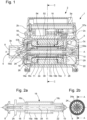
- FIG. 1 represents a section along the longitudinal axis AA of a high-speed centrifugal converter 1.
- the centrifugal converter comprises in a housing 2, a shaft 7 made of tungsten carbide or ceramic, mounted in rotation about a longitudinal axis AA passing through the front 2b and rear 2c faces, a first centrifugal compression wheel 8 and a second centrifugal compression wheel 10 mounted back to back at each end of the shaft 7, said first compression wheel 8 constituting a first compression stage and said second compression wheel 10 constituting a second compression stage. compression 10 constituting a second compression stage.
- the shaft 7 is hollow in this embodiment and contains a threaded rod 11, at each end of which is screwed one of the compression wheels 8, 10, which allows easy assembly and disassembly of the compression wheels.
- the two compression wheels 8 and 10 are driven on the same shaft 7, which allows for better energy efficiency and avoids a reducer.
- the rear of the compression wheels 8 and 10 has a labyrinth seal in order to control the pressures in the compressor and balance the axial forces.
- the casing 2 also contains a preferably synchronous electric motor positioned between the first compression wheel 8 and the second compression wheel 10 and arranged to rotate the shaft 7.
- the motor comprises a stator 14 and a rotor structure 16 which interact to form a synchronous electric motor with at least one permanent magnet 16a (brushless motor). More particularly, the stator 14 is formed by a coil 14a and two ferrite elements 14b, fixedly mounted relative to the casing 2.
- the rotor structure 16 comprises one or more permanent magnets 16a secured to the shaft 7, for example by gluing, and is covered with a titanium liner 16b. Titanium flanges 16c are fixed (for example by gluing) to the lateral ends of the liner and make it possible to ensure the resistance of the rotor to centrifugal forces at high speeds.
- the shaft 7 is rotatably mounted in the casing 2 about its longitudinal axis AA by means of at least one front radial bearing 18, one rear radial bearing 22 and one axial bearing 24, which is an integral part of the shaft 7.
- the centrifugal compressor 1 comprises a front radial bearing support 26 for supporting the front radial bearing 18, a rear radial bearing support 28 for supporting the rear radial bearing 22, arranged to be positioned around the shaft 7, respectively at the front and at the rear of the engine.
- a volute 29 is also provided between the rear radial bearing support 28 and the rear cover 3c.
- the volute 29 comprises the orifice leading to the tangential outlet 6 of fluid, after compression.
- An axial bearing support 30 is also provided to carry the axial bearing 24 arranged to be positioned around the shaft 7, between the first compression wheel 8 and the front radial bearing support 26. It is obvious that the axial bearing could be provided at the rear of the engine.
- the bearings are non-contact, aerodynamic type, in order to generate little friction. They do not require lubrication and require very little maintenance. More specifically, with reference to the Figures 2a, 2b , 3, 4 and 5 , the axial bearing 24 is an aerodynamic bearing. According to the present invention, it is part of the shaft 7 as such, that is to say that it is produced at the same time and in the same base material as the shaft 7 to form only one part with the shaft 7 in monobloc form at the end of its production.
- This axial bearing is constituted by a disk comprising on at least one of its faces first grooves 24a, preferably spiral on an annular zone at the periphery, arranged to create an air film.
- the axial bearing 24 comprises grooves or ribs 24a preferably spiral on the periphery of the axial bearing disk 24 on a front face and on a rear face obtained by a machining method explained below with reference to Figures 4 and 5 .
- the orientation of the grooves or ribs 24a may be different on the front face compared to the rear face or possibly identical.
- the axial bearing 24 with its grooves or ribs 24a makes it possible to keep the shaft 7 rotating in a longitudinally centered manner by generating air films on the front face and the rear face.
- the front 18 and rear 22 radial bearings are aerodynamic bearings, and the shaft 7 has, opposite the front 18 and rear 22 radial bearings, second grooves or ribs 32 arranged to create a film of air or gas when the shaft is rotated in the air or gas radial bearings.
- first centrifugal compression wheel 8 and the second centrifugal compression wheel 10 mounted back to back at each end of the shaft 7.
- a rotor structure 16 with at least one permanent magnet 16a of an electric motor is mounted or fixed for example on or in a central part of the shaft 7, to drive the shaft in rotation about the longitudinal axis AA, and an axial air or gas bearing 24 forming part of the shaft 7.
- a front radial air or gas bearing 18 is mounted on a first end of the shaft 7, and a rear radial air or gas bearing 22 is mounted on a second end of the shaft 7, as shown in FIG. Figure 2a .
- the rotor structure 16 with at least one permanent magnet 16a is fixed on the shaft 7 in a central position for the electric motor.
- FIG 3 shows a three-dimensional view of the shaft 7 with the axial bearing 24 at a first end of the shaft 7.
- a first portion of ribs or grooves 32 can be seen with the first radial bearing 18 shown in elevation above the ribs or grooves 32, and a second portion of ribs or grooves 32 with the second radial bearing 22 shown in elevation above these ribs or grooves 32.
- Ribs or grooves 24a are also shown on one face of the disc of the axial air or gas bearing 24 forming part of the shaft 7.
- the ribs or grooves 24a of a certain determined depth are made on an annular zone starting from the periphery of the disc and towards the centre of the disc.
- the ribs or grooves 24a and their arrangement are programmed in particular in the machining machine to activate the machining tool in order to produce all the ribs or grooves at once, that is to say by moving the tool holder, or the rotating disk in a single machining direction for example of the periphery of the disc at the bottom of the annular area of the ribs or grooves.
- Starting for example from the periphery of the disc on one of the faces and progressively portions of grooves are formed by back and forth movements of the machining tool in synchronism with the machining machine rotating the disc at a speed determined according to a sinusoidal programming.
- each start of all the grooves 24a is made by the rotation of the disk and the reciprocating movements of the machining tool. This is repeated continuously for the following groove or rib portions continuously from the first portion of the grooves and this until the end or bottom of the annular zone.
- the machining time per groove face of the disk is achieved in less than one minute, which differs significantly from previous machining carried out by laser beam.
- the machining machine is programmed to have a simultaneous synchronization of turning of the shaft 7 with the machining tool according to a sinusoidal programming to obtain a determined arrangement of the ribs or grooves 32 on the first portion to be machined of the shaft 7 for the front radial air or gas bearing 18.
- a sinusoidal programming to obtain a determined arrangement of the ribs or grooves 32 on the first portion to be machined of the shaft 7 for the front radial air or gas bearing 18.
- the determined arrangement of the ribs or grooves 32 made on the first portion of the first end of the shaft 7 is programmed in the machining machine.
- the ribs or grooves 32 each have a V shape, i.e. with a change of orientation in principle from the middle of the first portion of the shaft 7 to be machined. This makes it possible to maintain without mechanical contact the shaft rotated at high speed in the compressor in the air or gas radial bearings.
- the air or gas pressure in each aerodynamic radial bearing is such that the shaft is no longer in mechanical contact with the static radial bearing, thus avoiding any mechanical friction.
- the compressor 1 comprises a casing 2, made of aluminum, the upper face 2a of which is closed by an upper cover 3a and the front 2b and rear 2c faces are closed respectively by a front cover 3b and by a rear cover 3c.
- the side faces 2d of the casing are joined at their base to form a bottom 2e having, in cross section, a U shape.
- the upper cover 3a is positioned on the side of the electronic components of the compressor. Thus, access to the electronic components integrated in the compressor is easy, access being via the upper cover 3a.
- the front and rear covers 3b, 3c are used to reach the inside of the compressor (motor, rotor, bearings, etc.).
- a seal is inserted between the upper face of the casing 2 and the upper cover 3a. This seal protects the electronic components against dust and moisture.
- the casing 2 has an inlet for the fluid to be compressed 5 provided on the front cover 3b and a tangential outlet for the compressed fluid 6 provided on one of the side faces of the casing 2.
- the casing 2 comprises an internal through housing extending coaxially to the longitudinal axis AA between the front face 2b and the rear face 2c of the casing 2 and receiving the front radial bearing support 26 and the front radial bearing 18, the motor and its rotor structure 16 fixed on the shaft 7, the rear radial bearing support 28 and the rear radial bearing 22, the second compression wheel 10 and the volute 29.
- the internal housing On the side of the front face 2b, the internal housing is closed by the front cover 3b which integrates the first compression wheel 8, the axial bearing support 30 and the axial bearing 24.
- the inner housing is closed by the rear cover 3c.
- At least one orifice for example the point referenced 57a, arranged to allow the fluid to be compressed circulating in the channels to enter the motor and circulate between the stator 14 and the rotor structure 16 and at least one orifice, for example the points referenced 57b, arranged to allow the fluid to be compressed to exit the motor and join said channels after having cooled the motor.
- At least one orifice is advantageously provided, for example the points referenced 59a on the figure 1 arranged to allow the fluid to be compressed circulating in the channels 54 to circulate near the axial 24, front radial 18 and rear radial 22 bearings, and at least one orifice corresponding for example to the same points referenced 57b arranged to allow the fluid to be compressed to join said channels 54 after having cooled said axial 24, front radial 18 and rear radial 22 bearings.
- the fluid to be compressed passes into the channels 54 through the compressor parts located along the longitudinal axis between the first compression stage and the second compression stage to reach the second compression stage.
- the fluid to be compressed when it passes between the inner wall 52 and the ferrite elements 14b of the motor, cools the latter and recovers the calories lost from the motor in order to increase its efficiency before entering the second compression stage.
- the orifices 57a, 57b, 59a make it possible to achieve a slight deviation of the flow so that the fluid to be compressed also circulates between the stator 14 and the rotor structure 16 and in the bearings to cool these elements and recover the heat losses at the motor and the heat losses due to friction in the bearings.
- the centrifugal compressor 1 allows very high rotation speeds to be achieved, between 100,000 rpm and 500,000 rpm. It allows the fluid compressed in the first compression stage to pass substantially throughout the system to recover all the waste heat, and in particular the heat lost at the engine, bearings and electronic components, in order to increase its efficiency before entering the second compression stage (as the temperature of the fluid to be compressed increases, its pressure also increases).
- the use of only the fluid to be compressed to cool the compressor, without the aid of an additional cooling circuit, as well as the arrangement of the electronic components in the compressor to have electronics integrated into the casing make it possible to obtain a very compact compressor.
- the compressor according to the invention therefore has a high rotation speed and a high compression ratio while occupying a restricted volume.
- a compressor according to the invention has a compression ratio greater than 3, and a power of the order of 4 kW for dimensions L ⁇ l ⁇ h in cm of the order of 14 x 8 x 11 for a weight of only 1.6 kg.
- the compressor according to the invention can be used with air or gas to supply fuel cells, or any other system which uses compressed air (industrial compressors, medical compressors, boat compressors, etc.).
- the compressor according to the invention can be used in a mobile HVAC (heating, ventilation, air conditioning and air conditioning) system, such as in electric, hybrid or hydrogen vehicles.
- a mobile HVAC heating, ventilation, air conditioning and air conditioning
- the centrifugal compressor can also be used in a stationary system with a refrigerant gas, such as a heat pump.
- the centrifugal compressor can also be used with natural gas.
- FIG. 4 represents a machining machine 100 for producing ribs or grooves on portions of the first end and the second end of the shaft 7, and also for producing ribs or grooves on a first face of the axial bearing disc 24 forming part of the shaft 7 or also on a second face of the axial bearing disc 24 forming part of the shaft 7.
- the machining machine 100 comprises a machining lathe 130 with two spindles 140 for holding the shaft 7 at both ends of the shaft 7 and rotating it when machining the ribs or grooves at a determined rotational speed ⁇ .
- a first spindle 140 is located on a first vertical column or wall 102 of the machining machine 100, while the second spindle 140 is located on a second vertical column or wall 103 opposite the first vertical column or wall 102.
- the two vertical walls 102, 103 of the machining machine 100 are connected by a base 101 in which is arranged a means for guiding at least one tool holder 160 capable of carrying at least one machining tool 120 or two machining tools 120, 121 or several other different machining tools.
- the guiding means of the tool holder 160 in the base 101 of the machining machine 100 can be moved in a longitudinal direction A-A on one or two guide rails, for example not shown, in the base 101.
- the tool holder 160 can be moved parallel and preferably horizontally to the shaft 7 so as to place the first machining tool 120 in a machining position as already explained above.
- the first machining tool 120 is oriented perpendicular to the portion of the shaft 7 so as to be able to carry out the machining of the ribs or grooves on one of the portions to be machined of the shaft 7.
- the tool holder 160 is again moved parallel to the shaft 7 to move towards the second portion of the shaft to be machined.
- a second machining tool 121 fixed to the same tool holder 160 than the first machining tool 120, or to another tool holder not shown, but oriented in a direction perpendicular to the direction of the first machining tool.
- This second machining tool 121 can be used to carry out the machining of the ribs or grooves on at least one face of the axial bearing disc 24 forming part of the shaft 7. To do this, the tool holder 160 is moved parallel to the shaft 7 to the axial bearing disc 24. Once positioned near the disc, the second machining tool 121 is driven for the machining of the ribs or grooves on at least one of the faces of the axial bearing disc 24.
- the pins 140 which keep the shaft 7 rotating, can move in a longitudinal machining direction for producing the ribs or grooves.
- the shaft 7 is in tubular form so that it can be fixed and moved in a longitudinal direction. With the shaft 7 in tubular form, this allows the two pins 140 to have their ends partially inserted into the inner tube of the shaft at both ends of the shaft to keep it blocked and rotate it at a determined rotational speed ⁇ for machining.
- the two pins 140 with the shaft 7 to be machined can move in a longitudinal direction during the machining operation.
- the machining machine 100 further comprises at least one tool holder 160, which is connected to the structure of the machining lathe 130.
- the tool holder 160 carries a first machining tool 120 whose machining head can come into contact with the shaft 7 to machine the grooves or ribs can perform reciprocating movements according to a programming of the machining machine 100.
- At least the end of the head of the first machining tool 120 can be made of diamond to machine the ribs or grooves on the shaft 7 in tungsten carbide or ceramic.
- the tool holder 160 with the first machining tool 120 can also in an alternative embodiment be moved together in a longitudinal machining direction instead of the shaft 7 for machining ribs or grooves on the shaft.
- the back-and-forth movements of the first machining tool 120 may also be provided to modify the frequency of the back-and-forth movements of the first machining tool 120 according to programming carried out in the machining machine 100.
- the back-and-forth movements of the machining tool are synchronized by sinusoidal programming carried out in the machining machine, as well as to the desired and programmed arrangement of the ribs or grooves to be produced on the portion of the shaft 7 and/or the disk of the axial bearing 24 of the shaft 7.
- the axial bearing 24 of the shaft 7 is made with the shaft 7 in the same material in the monobloc form.
- the shaft 7 and the axial bearing 24 of the shaft can therefore be made at the same time either by a molding operation depending on the material used, or preferably by using at least one machining tool of a tool holder of the machining machine 100, which is subsequently used for machining the grooves or ribs on the front and rear portions of the shaft 7. In this case, it is possible to use the first machining tool 120 of the tool holder 160.
- this blank initial of the shaft 7, which may already be in tubular form may initially have a diameter corresponding substantially to the final external diameter of the axial bearing 24 to be produced.
- the blank is fixed to the two spindles 140 of the machining machine 100 to be driven in rotation about a longitudinal axis.
- the first machining tool 120 which must be of a more significant abrasive material, harder than the material of the blank of the shaft 7, and moved from a first end of the rotating shaft to a first position of the shaft 7 corresponding to the position of a face of the disk of the axial bearing 24 to be produced.
- this first machining operation there is the blank of the rotating shaft, as well as the machining tool 120 to be able to remove a first thin layer of material from the blank of the shaft.
- machining must also be carried out by removing thin layers on the other side of the shaft blank by changing the direction of the tubular blank to fix the shaft blank to the two spindles 140 in an opposite direction and repeating the operations with the machining tool 120 on its tool holder 160 as before. It is thus easier to change the direction of the shaft blank between the spindles 140, than to have to move the tool holder 160 with the machining tool 120 from another location on the machining machine 100.
- the ribs or grooves on the front and rear portions of the shaft can be machined using the first machining tool 120 connected to the tool holder 160.
- the shaft 7 to be machined is made of tungsten carbide or ceramic.
- the machining tool 120 generally comprises a head diamond machining. This makes it possible to produce all the ribs or grooves on a first portion to be machined of the first end of the shaft 7 from the start of the first portion to the end of the first portion at once by reciprocating movements of the machining tool 120 and movement in a longitudinal machining direction of the rotating shaft 7 according to the programming of the machining machine 100 or also by longitudinal movement of the first tool holder 160, or of the first tool 120 in the tool holder 160.
- a second machining tool 121 must be provided mounted on the tool holder 160 in a direction perpendicular to the first machining tool 120 to produce the ribs or grooves on one face of the disk of the axial bearing 24, or on both faces of the disk by a change in direction of the shaft 7 fixed between the two spindles 140.
- the machining of the ribs or grooves on a first portion before a second rear portion successively of the shaft can be carried out by the first machining tool 120.
- a change in orientation of the ribs or grooves can occur when passing half of the first portion to be machined and the second portion to be machined of the shaft 7 according to a programming of the machining machine so as to obtain V-shaped grooves over the length of the first and second machined portions in order to generate air or gas pressure in a front radial bearing arranged on the first portion or in a rear radial bearing arranged on the second portion during operation of the compressor with the rotation of the shaft 7 above a limit speed so as to no longer have mechanical contact with the front and rear radial bearing(s).
- the second machining tool 121 For machining the axial bearing 24, which is in the form of a disc, only the second machining tool 121 is used, which can be mounted on the tool holder 160 which can be moved longitudinally along the axis AA.
- the ribs or grooves and their arrangement are programmed into the machine.
- machining tool 100 to activate the second machining tool 121 to produce all the ribs or grooves at once on a first face of the disk by moving the machining tool, or the disk rotated in a single machining direction from the periphery of the disk to the bottom of the annular area of the ribs or grooves or vice versa, and by back-and-forth movements of the machining tool 121 according to the programming of the machining machine 100.
- the two faces of the disk of the axial bearing 24 can be machined by the second machining tool by switching the direction of the shaft 7 between the two spindles 140.
- the ribs or grooves may be made in the form of a spiral in the same orientation on both faces or two different orientations in order to generate air films through the grooves when the shaft 7 rotates to maintain the axis in a well-centered longitudinal position during operation of the centrifugal compressor.
- both the first machining tool 120 and the second machining tool 121 can be moved in the tool holder 160 in a first direction or in a second reverse direction to come into contact with a portion of the shaft 7 to be machined for the first machining tool 120 or to move away from it as symbolically shown by the arrows in the tool holder 160 or in each of the machining tools 120, 121.
- FIG. 5 is partly taken from the figure 4 of the machining machine 100.
- this tool holder 160 is movable longitudinally for example on one or more guide rails arranged in the base 101 of the machining machine 100.
- This second embodiment of the machining machine 100 seems easier to use than the first embodiment presented above at figure 4 , but without necessarily being more rapid in obtaining the ribs or grooves on the portions of the shaft 7 and on the disc of the axial bearing 24. All the elements presented in this figure 5 , which are identical to the elements described with reference to the figure 4 are therefore not repeated.
- the tool holder 160 may be provided with more than two machining tools, but with only one machining tool in operation for machining the ribs or grooves on one or two portions of the shaft 7 or on one face or two faces of the axial bearing disc 24.
Landscapes
- Engineering & Computer Science (AREA)
- Mechanical Engineering (AREA)
- General Engineering & Computer Science (AREA)
- Physics & Mathematics (AREA)
- Fluid Mechanics (AREA)
- Ocean & Marine Engineering (AREA)
- Structures Of Non-Positive Displacement Pumps (AREA)
- Turning (AREA)
- Sliding-Contact Bearings (AREA)
Priority Applications (7)
| Application Number | Priority Date | Filing Date | Title |
|---|---|---|---|
| EP23171475.9A EP4459129A1 (de) | 2023-05-04 | 2023-05-04 | Verfahren zur bearbeitung von rippen oder nuten einer welle für luft- oder gaslager eines verdichters |
| EP24169647.5A EP4459130A1 (de) | 2023-05-04 | 2024-04-11 | Verfahren zur bearbeitung von rippen oder nuten an einer welle für luft- oder gaslager eines verdichters |
| US18/641,895 US20240367240A1 (en) | 2023-05-04 | 2024-04-22 | Method for machining ribs or grooves on a shaft for air or gas bearings of a compressor |
| JP2024072657A JP2024160964A (ja) | 2023-05-04 | 2024-04-26 | コンプレッサーの空気ないしガスベアリングのためにシャフト上にリブないし溝を加工して形成する方法 |
| KR1020240057966A KR20240161592A (ko) | 2023-05-04 | 2024-04-30 | 압축기의 공기 또는 가스 베어링을 위한 샤프트에 리브 또는 홈을 가공하기 방법 |
| CN202420957600.6U CN223062719U (zh) | 2023-05-04 | 2024-05-06 | 离心压缩机 |
| CN202410548233.9A CN118896080A (zh) | 2023-05-04 | 2024-05-06 | 针对压缩机的空气或气体轴承在轴上加工肋或凹槽的方法 |
Applications Claiming Priority (1)
| Application Number | Priority Date | Filing Date | Title |
|---|---|---|---|
| EP23171475.9A EP4459129A1 (de) | 2023-05-04 | 2023-05-04 | Verfahren zur bearbeitung von rippen oder nuten einer welle für luft- oder gaslager eines verdichters |
Publications (1)
| Publication Number | Publication Date |
|---|---|
| EP4459129A1 true EP4459129A1 (de) | 2024-11-06 |
Family
ID=86329212
Family Applications (2)
| Application Number | Title | Priority Date | Filing Date |
|---|---|---|---|
| EP23171475.9A Withdrawn EP4459129A1 (de) | 2023-05-04 | 2023-05-04 | Verfahren zur bearbeitung von rippen oder nuten einer welle für luft- oder gaslager eines verdichters |
| EP24169647.5A Pending EP4459130A1 (de) | 2023-05-04 | 2024-04-11 | Verfahren zur bearbeitung von rippen oder nuten an einer welle für luft- oder gaslager eines verdichters |
Family Applications After (1)
| Application Number | Title | Priority Date | Filing Date |
|---|---|---|---|
| EP24169647.5A Pending EP4459130A1 (de) | 2023-05-04 | 2024-04-11 | Verfahren zur bearbeitung von rippen oder nuten an einer welle für luft- oder gaslager eines verdichters |
Country Status (5)
| Country | Link |
|---|---|
| US (1) | US20240367240A1 (de) |
| EP (2) | EP4459129A1 (de) |
| JP (1) | JP2024160964A (de) |
| KR (1) | KR20240161592A (de) |
| CN (2) | CN223062719U (de) |
Citations (6)
| Publication number | Priority date | Publication date | Assignee | Title |
|---|---|---|---|---|
| JPH10328983A (ja) * | 1997-03-25 | 1998-12-15 | Nippon Seiko Kk | 円筒体の製作方法 |
| JP2002036004A (ja) * | 2000-07-25 | 2002-02-05 | National Institute Of Advanced Industrial & Technology | 流体軸受の製造方法及び製造装置 |
| EP3557078A1 (de) * | 2018-04-20 | 2019-10-23 | Belenos Clean Power Holding AG | Fluidverdichter |
| CN111365285A (zh) * | 2018-12-25 | 2020-07-03 | 珠海格力电器股份有限公司 | 压缩机、冷媒循环系统和制冷设备 |
| CN111478497B (zh) * | 2020-04-21 | 2021-07-13 | 北京稳力科技有限公司 | 两级串联离心式气体压缩机及其电机 |
| EP4180154A1 (de) * | 2021-11-16 | 2023-05-17 | Belenos Clean Power Holding AG | Verfahren zur bearbeitung von rippen oder nuten von luft- oder gaslagern eines kompressors |
Family Cites Families (3)
| Publication number | Priority date | Publication date | Assignee | Title |
|---|---|---|---|---|
| JPH10328902A (ja) * | 1997-05-26 | 1998-12-15 | Sony Corp | 螺旋溝形成装置 |
| JPH1119804A (ja) * | 1997-07-01 | 1999-01-26 | Sony Corp | 螺旋溝加工装置及び加工方法 |
| JP2013185658A (ja) * | 2012-03-08 | 2013-09-19 | Samsung Electro-Mechanics Japan Advanced Technology Co Ltd | 回転機器およびその生産方法 |
-
2023
- 2023-05-04 EP EP23171475.9A patent/EP4459129A1/de not_active Withdrawn
-
2024
- 2024-04-11 EP EP24169647.5A patent/EP4459130A1/de active Pending
- 2024-04-22 US US18/641,895 patent/US20240367240A1/en active Pending
- 2024-04-26 JP JP2024072657A patent/JP2024160964A/ja active Pending
- 2024-04-30 KR KR1020240057966A patent/KR20240161592A/ko active Pending
- 2024-05-06 CN CN202420957600.6U patent/CN223062719U/zh active Active
- 2024-05-06 CN CN202410548233.9A patent/CN118896080A/zh active Pending
Patent Citations (6)
| Publication number | Priority date | Publication date | Assignee | Title |
|---|---|---|---|---|
| JPH10328983A (ja) * | 1997-03-25 | 1998-12-15 | Nippon Seiko Kk | 円筒体の製作方法 |
| JP2002036004A (ja) * | 2000-07-25 | 2002-02-05 | National Institute Of Advanced Industrial & Technology | 流体軸受の製造方法及び製造装置 |
| EP3557078A1 (de) * | 2018-04-20 | 2019-10-23 | Belenos Clean Power Holding AG | Fluidverdichter |
| CN111365285A (zh) * | 2018-12-25 | 2020-07-03 | 珠海格力电器股份有限公司 | 压缩机、冷媒循环系统和制冷设备 |
| CN111478497B (zh) * | 2020-04-21 | 2021-07-13 | 北京稳力科技有限公司 | 两级串联离心式气体压缩机及其电机 |
| EP4180154A1 (de) * | 2021-11-16 | 2023-05-17 | Belenos Clean Power Holding AG | Verfahren zur bearbeitung von rippen oder nuten von luft- oder gaslagern eines kompressors |
Also Published As
| Publication number | Publication date |
|---|---|
| KR20240161592A (ko) | 2024-11-12 |
| JP2024160964A (ja) | 2024-11-15 |
| CN223062719U (zh) | 2025-07-04 |
| EP4459130A1 (de) | 2024-11-06 |
| US20240367240A1 (en) | 2024-11-07 |
| CN118896080A (zh) | 2024-11-05 |
Similar Documents
| Publication | Publication Date | Title |
|---|---|---|
| EP4180154A1 (de) | Verfahren zur bearbeitung von rippen oder nuten von luft- oder gaslagern eines kompressors | |
| EP2323807B1 (de) | Verfahren und vorrichtung zum polieren von schaufelrädern für turbomaschinen | |
| EP0279739B1 (de) | Kältemaschine, insbesondere mit Vuilleumier-Zyklus, mit durch Gaslager unterstützten Kolben | |
| EP3557078A1 (de) | Fluidverdichter | |
| FR2730525A1 (fr) | Pompe electrique de carburant pour moteur | |
| CA2514106C (fr) | Procede de fabrication de pieces constitutives d'une aube creuse par laminage | |
| EP3557080A1 (de) | Wärmepumpe, die einen fluidverdichter umfasst | |
| EP2198438B1 (de) | Verfahren und einrichtung zum herstellen von elektrischen energiespeicherbaugruppen | |
| CH719147A2 (fr) | Procédé d'usinage de nervures de paliers à air ou à gaz d'un compresseur. | |
| EP4459129A1 (de) | Verfahren zur bearbeitung von rippen oder nuten einer welle für luft- oder gaslager eines verdichters | |
| CH720760A2 (fr) | Procédé d'usinage de nervures ou de rainures d'un arbre pour des paliers à air ou à gaz d'un compresseur | |
| EP3557081A1 (de) | Brennstoffzelle, die einen fluidverdichter umfasst | |
| EP4458497A1 (de) | Verfahren zum bearbeiten von rippen oder rillen von luft- oder gaslagern eines rotierenden wellenteils eines verdichters und montage der komponenten des werkstücks | |
| CH720761A2 (fr) | Procédé d'usinage de nervures ou rainures de paliers à air ou à gaz d'une pièce à arbre de rotation d'un compresseur | |
| WO2001065672A1 (fr) | Refroidissement d'un frein active par les courants de foucault | |
| EP3983170A1 (de) | Spindel mit piezoelektrischen aktuatoren | |
| EP3581298B1 (de) | Herstellungsverfahren einer turbine, insbesondere für turbopumpe | |
| WO2019115886A1 (fr) | Amortisseur de vibrations pour une aube de rotor de turbomachine | |
| CH424954A (fr) | Moteur électrique à collecteur | |
| FR3100843A1 (fr) | Support de palier de turbomachine à récupération d’huile améliorée | |
| FR3047776A1 (fr) | Turbomachine et son procede de montage | |
| EP4277762A1 (de) | Verbessertes verfahren zur herstellung eines teils durch generative fertigung | |
| FR3163226A1 (fr) | Ensemble de rotor pour une machine électrique à flux axial, notamment de véhicule automobile, et machine électrique à flux axial le comprenant | |
| FR3163227A1 (fr) | Ensemble de rotor pour une machine électrique à flux axial, notamment de véhicule automobile, et machine électrique à flux axial le comprenant | |
| FR3163228A1 (fr) | Ensemble de rotor pour une machine électrique à flux axial, notamment de véhicule automobile, et machine électrique à flux axial le comprenant |
Legal Events
| Date | Code | Title | Description |
|---|---|---|---|
| PUAI | Public reference made under article 153(3) epc to a published international application that has entered the european phase |
Free format text: ORIGINAL CODE: 0009012 |
|
| STAA | Information on the status of an ep patent application or granted ep patent |
Free format text: STATUS: THE APPLICATION HAS BEEN PUBLISHED |
|
| AK | Designated contracting states |
Kind code of ref document: A1 Designated state(s): AL AT BE BG CH CY CZ DE DK EE ES FI FR GB GR HR HU IE IS IT LI LT LU LV MC ME MK MT NL NO PL PT RO RS SE SI SK SM TR |
|
| RAP1 | Party data changed (applicant data changed or rights of an application transferred) |
Owner name: THE SWATCH GROUP RESEARCH AND DEVELOPMENT LTD |
|
| P01 | Opt-out of the competence of the unified patent court (upc) registered |
Free format text: CASE NUMBER: APP_6838/2025 Effective date: 20250210 |
|
| STAA | Information on the status of an ep patent application or granted ep patent |
Free format text: STATUS: THE APPLICATION IS DEEMED TO BE WITHDRAWN |
|
| 18D | Application deemed to be withdrawn |
Effective date: 20250507 |