EP4458779A1 - Abwasserbehandlungsvorrichtung und abwasserbehandlungsverfahren - Google Patents
Abwasserbehandlungsvorrichtung und abwasserbehandlungsverfahren Download PDFInfo
- Publication number
- EP4458779A1 EP4458779A1 EP23749741.7A EP23749741A EP4458779A1 EP 4458779 A1 EP4458779 A1 EP 4458779A1 EP 23749741 A EP23749741 A EP 23749741A EP 4458779 A1 EP4458779 A1 EP 4458779A1
- Authority
- EP
- European Patent Office
- Prior art keywords
- region
- denitrification
- air diffusion
- concentration
- combined
- Prior art date
- Legal status (The legal status is an assumption and is not a legal conclusion. Google has not performed a legal analysis and makes no representation as to the accuracy of the status listed.)
- Pending
Links
Images


Classifications
-
- C—CHEMISTRY; METALLURGY
- C02—TREATMENT OF WATER, WASTE WATER, SEWAGE, OR SLUDGE
- C02F—TREATMENT OF WATER, WASTE WATER, SEWAGE, OR SLUDGE
- C02F3/00—Biological treatment of water, waste water, or sewage
- C02F3/30—Aerobic and anaerobic processes
- C02F3/301—Aerobic and anaerobic treatment in the same reactor
-
- C—CHEMISTRY; METALLURGY
- C02—TREATMENT OF WATER, WASTE WATER, SEWAGE, OR SLUDGE
- C02F—TREATMENT OF WATER, WASTE WATER, SEWAGE, OR SLUDGE
- C02F3/00—Biological treatment of water, waste water, or sewage
- C02F3/006—Regulation methods for biological treatment
-
- C—CHEMISTRY; METALLURGY
- C02—TREATMENT OF WATER, WASTE WATER, SEWAGE, OR SLUDGE
- C02F—TREATMENT OF WATER, WASTE WATER, SEWAGE, OR SLUDGE
- C02F3/00—Biological treatment of water, waste water, or sewage
- C02F3/30—Aerobic and anaerobic processes
- C02F3/302—Nitrification and denitrification treatment
-
- C—CHEMISTRY; METALLURGY
- C02—TREATMENT OF WATER, WASTE WATER, SEWAGE, OR SLUDGE
- C02F—TREATMENT OF WATER, WASTE WATER, SEWAGE, OR SLUDGE
- C02F2101/00—Nature of the contaminant
- C02F2101/10—Inorganic compounds
- C02F2101/16—Nitrogen compounds, e.g. ammonia
- C02F2101/163—Nitrates
-
- C—CHEMISTRY; METALLURGY
- C02—TREATMENT OF WATER, WASTE WATER, SEWAGE, OR SLUDGE
- C02F—TREATMENT OF WATER, WASTE WATER, SEWAGE, OR SLUDGE
- C02F2209/00—Controlling or monitoring parameters in water treatment
- C02F2209/001—Upstream control, i.e. monitoring for predictive control
-
- C—CHEMISTRY; METALLURGY
- C02—TREATMENT OF WATER, WASTE WATER, SEWAGE, OR SLUDGE
- C02F—TREATMENT OF WATER, WASTE WATER, SEWAGE, OR SLUDGE
- C02F2209/00—Controlling or monitoring parameters in water treatment
- C02F2209/14—NH3-N
-
- C—CHEMISTRY; METALLURGY
- C02—TREATMENT OF WATER, WASTE WATER, SEWAGE, OR SLUDGE
- C02F—TREATMENT OF WATER, WASTE WATER, SEWAGE, OR SLUDGE
- C02F2209/00—Controlling or monitoring parameters in water treatment
- C02F2209/15—N03-N
-
- C—CHEMISTRY; METALLURGY
- C02—TREATMENT OF WATER, WASTE WATER, SEWAGE, OR SLUDGE
- C02F—TREATMENT OF WATER, WASTE WATER, SEWAGE, OR SLUDGE
- C02F3/00—Biological treatment of water, waste water, or sewage
- C02F3/02—Aerobic processes
- C02F3/12—Activated sludge processes
- C02F3/20—Activated sludge processes using diffusers
-
- Y—GENERAL TAGGING OF NEW TECHNOLOGICAL DEVELOPMENTS; GENERAL TAGGING OF CROSS-SECTIONAL TECHNOLOGIES SPANNING OVER SEVERAL SECTIONS OF THE IPC; TECHNICAL SUBJECTS COVERED BY FORMER USPC CROSS-REFERENCE ART COLLECTIONS [XRACs] AND DIGESTS
- Y02—TECHNOLOGIES OR APPLICATIONS FOR MITIGATION OR ADAPTATION AGAINST CLIMATE CHANGE
- Y02W—CLIMATE CHANGE MITIGATION TECHNOLOGIES RELATED TO WASTEWATER TREATMENT OR WASTE MANAGEMENT
- Y02W10/00—Technologies for wastewater treatment
- Y02W10/10—Biological treatment of water, waste water, or sewage
Definitions
- the present disclosure relates to a wastewater treatment apparatus and a wastewater treatment method.
- ammonia nitrogen included in the wastewater is converted to nitrate nitrogen due to the action of nitrifying bacteria in an aerobic region where an air diffusion treatment is carried out, and the nitrate nitrogen is channeled out as nitrogen gas due to the action of denitrifying bacteria in a denitrification region where the air diffusion treatment is not carried out (for example, refer to Patent Document 1).
- Patent Document 1 Japanese Laid-Open Patent Application No. 2008-221162
- Patent Document 1 requires a partitioning plate or a stirring vane, thus presenting a problem in terms of equipment costs.
- the wastewater treatment apparatus comprises: a tank that has a wastewater inlet, a flow channel where wastewater treatment is carried out, and a treated-water outlet; an air diffusion device in which a plurality of air diffusion parts are disposed along the flow channel of the tank and at the bottom of the flow channel; a first detection device that detects the concentration of nitrate nitrogen in the wastewater; a second detection device that detects the concentration of ammonia nitrogen in the wastewater, the second detection device being provided downstream of the first detection device; and a control device that controls the amount of air diffused from the plurality of air diffusion parts of the air diffusion device, the control device forming a first-half aerobic region, a first-half combined-use region where both nitrification and denitrification progress, a denitrification region, a second-half combined-use region where both nitrification and denitrification progress, and a second-half aerobic region in the stated order from the upstream side along the flow channel, and furthermore producing first and second swirl flows constituting a
- the control device controls the air diffusion amount in the first-half aerobic region and the first-half combined-use region on the basis of the concentration of nitrate nitrogen detected by the first detection device and controls the air diffusion amount in the second-half combined-use region and the second-half aerobic region on the basis of the concentration of ammonia nitrogen detected by the second detection device.
- the first swirl flow rises in the first-half combined-use region, advances downstream at the water-surface side of the denitrification region, descends near the center of the denitrification region, and advances upstream at the bottom side of the denitrification region.
- the second swirl flow rises in the second-half combined use region, advances upstream at the water-surface side of the denitrification region, descends near the center of the denitrification region, and advances downstream at the bottom side of the denitrification region.
- the wastewater treatment method is executed by a wastewater treatment apparatus comprising: a tank having a wastewater inlet, a flow channel where wastewater treatment is carried out, and a treated-water outlet; an air diffusion device in which a plurality of air diffusion parts are disposed along the flow channel of the tank and at the bottom of the flow channel; a first detection device that detects the concentration of nitrate nitrogen in the wastewater; and a second detection device that detects the concentration of ammonia nitrogen in the wastewater, the second detection device being provided downstream of the first detection device, the method comprising a step for controlling the amount of air diffused from the plurality of air diffusion parts of the air diffusion device, forming a first-half aerobic region, a first-half combined-use region where both nitrification and denitrification progress, a denitrification region, a second-half combined-use region where both nitrification and denitrification progress, and a second-half aerobic region in the stated order from the upstream side along the flow channel, and furthermore producing first
- wastewater treatment apparatus (referred to below as the treatment apparatus, as appropriate) according to the present disclosure is particularly suitable for treating sewage.
- Sewage or another form of wastewater is introduced into an initial precipitation reservoir (not shown), initially precipitated sludge sinks and is separated out, and a supernatant of the wastewater is introduced into the treatment apparatus according to the present disclosure as water to be treated.
- the water to be treated (the "wastewater” that is to be treated by the wastewater treatment apparatus according to the present disclosure) includes ammonia or another nitrogen component that is derived from excreta or the like.
- the wastewater is nitrified and denitrified so that the concentration of nitrogen in the wastewater can be reduced and so that the concentration of ammonia nitrogen can be brought to or below a permissible concentration before treated water is discharged.
- FIGS. 1 and 2 show one embodiment of the treatment apparatus according to the present disclosure.
- the treatment apparatus 100 for treating wastewater shown in FIG. 1 comprises a treatment tank (referred to below as the tank, as appropriate) 200 in which wastewater is treated, an air diffusion device 300 that supplies oxygen-containing air (referred to below as the air, as appropriate) into the wastewater, a control system 400 that controls the air diffusion device 300, a first detection device 403, and a second detection device 404.
- the wastewater treatment apparatus is configured so that the nitrification and denitrification described earlier are carried out simultaneously in one tank (i.e., a single tank) and is also referred to as a single-tank nitrification and denitrification apparatus.
- the tank 200 forms a gravity flow tank structure, the tank 200 having a wastewater inlet 201 at one end, having a treated-water outlet 202 at the other end, and having a wastewater flow channel 203 that extends from the inlet 201 to the outlet 202.
- a partition wall 204 is disposed partway along a flow channel 203 and in a portion near an inlet 201, and such that wastewater flowing in through the inlet 201 flows into an anaerobic region 205 partitioned by the partition wall 204.
- the anaerobic region 205 plays a role in mixing the wastewater introduced via the initial precipitation reservoir (not shown) with returned sludge and releasing phosphorus that is contained in the returned sludge or in organic matter in the wastewater under anaerobic conditions.
- the phosphorus is subsequently captured in active sludge by an aerobic region, making it possible to reduce the phosphorus content of the wastewater.
- providing the partition wall 204 and the anaerobic region 205 is not essential, and it is permissible to use a tank 200 that does not have the partition wall 204 or the anaerobic region 205.
- the wording "single tank" means that the portion excluding the anaerobic region 205 forms one tank that does not have a partition wall.
- the air diffusion device 300 comprises a plurality of air diffusion parts 306.
- the plurality of air diffusion parts 306 are disposed along the flow channel 203 of the tank 200 and at the bottom (lower section) of the flow channel 203.
- the air diffusion device 300 has a first blower 301, a second blower 302, and piping 303 linked to the first and second blowers 301, 302, the piping 303 being linked to the tank 200 via a first electric valve 304 and a second electric valve 305.
- the plurality of air diffusion parts are installed at the bottom of the tank 200 and along the flow channel 203.
- a pressure detection device 308 is attached partway along a flow channel in the piping 303 extending to the first electric valve 304.
- the present embodiment has two blowers, specifically the first and second blowers 301, 302, but it is also permissible to have one blower or three or more blowers.
- the piping 303 branches into a plurality of portions through the first and second electric valves 304, 305 and is connected to each of the air diffusion parts 306 via a manual valve 307. Therefore, adjusting the output of the first and second blowers 301, 302, the opening degrees of the first and second electric valves 304, 305, or the opening degrees of the manual valves 307 connected to each of the air diffusion parts 306 makes it possible to adjust the air diffusion amount sprayed from the air diffusion parts 306.
- Manual valves 307a are positioned at boundary sections between regions that shall be described later.
- adjusting the amount of air diffused from the air diffusion parts 306 of the air diffusion device 300 in the remainder of the region passing through the partition wall 204 in the flow channel 203 of the tank 200 results in a first-half aerobic region 206, an upstream-side first-half combined-use region 209f, a denitrification region 207, a downstream-side second-half combined-use region 209b, and a second-half aerobic region 208 being formed in order from the side near the inlet 201.
- the first-half aerobic region 206 and the first-half combined-use region 209f positioned downstream therefrom constitute regions pertaining to a first-half aerobic region.
- the second-half combined-use region 209b positioned downstream from the denitrification region 207 and the second-half aerobic region 208 positioned downstream from the second-half combined-use region 209b constitute regions pertaining to a second-half aerobic region.
- No partition wall is present at portions where the first-half aerobic region 206, the first-half combined-use region 209f, the denitrification region 207, the second-half combined-use region 209b, and the second-half aerobic region 208 are disposed in the flow channel 203, and these regions are formed by adjusting the air diffusion amount.
- the first-half combined-use region 209f and the second-half combined-use region 209b are omitted for convenience.
- the first-half combined-use region 209f and the second-half combined-use region 209b may be referred to collectively as combined-use regions 209.
- the air diffusion parts 306 disposed in the first-half aerobic region 206, the first-half combined-use region 209f, the downstream-side second-half combined-use region 209b, and the second-half aerobic region 208 are configured to diffuse air once the corresponding manual valves 307, 307a are opened, and the air diffusion parts 306 disposed in the denitrification region 207 are configured to not diffuse air or to reduce the air diffusion amount once the corresponding manual valves 307, 307a are closed or throttled.
- a diffused-air control in the present disclosure including a step in which a control device 400 controls the amount of air diffused from the air diffusion parts 306 to produce first and second swirl flows constituting a pair, shall now be described with reference to arrows U1, U2, R1, R2, L1, L2, and D in FIG. 2 .
- the first swirl flow is indicated by the arrows U1, R1, D, and L2
- the second swirl flow is indicated by the arrows U2, L1, D, and R2.
- the arrows U1 and U2 indicate rising flows, the arrow R1 indicates a water-surface forward flow, the arrow R2 indicates a bottom-surface forward flow, the arrow L1 indicates a water-surface reverse flow, the arrow L2 indicates a bottom-surface reverse flow, and the arrow D indicates a descending flow.
- the combined use regions 209 where both nitrification and denitrification progress are respectively formed on the outer side of the denitrification region 207 adjacent to the regions pertaining to the first-half aerobic region (the first-half aerobic region 206 and the first-half combined-use region 209f) and on the outer side of the denitrification region 207 adjacent to the regions pertaining to the second-half aerobic region (the second-half combined-use region 209b and the second-half aerobic region 208).
- the combined-use regions 209 serve as buffer regions; therefore, even if no partition wall is provided, it is possible for wastewater having a high concentration of dissolved oxygen in the first-half aerobic region 206 to mix with wastewater having a low concentration of dissolved oxygen in the denitrification region 207 due to a push-out flow or for wastewater having a high concentration of dissolved oxygen in the second-half aerobic region 208 to mix with wastewater having a low concentration of dissolved oxygen in the denitrification region 207 due to a flow that is the reverse of the push-out flow, and it is possible to effectively avoid loss of an oxygen-free or low-oxygen state in the denitrification region 207 and to cause a denitrification reaction to sufficiently progress.
- a denitrification treatment is carried out in the combined-use regions as well as the denitrification region, and a nitrification treatment is also carried out in the combined-use regions; therefore, the denitrification region can be expanded without reducing the size of the aerobic regions, and it is possible to increase a denitrification treatment amount that can be employed as a target at the same tank volume or to reduce the tank volume while maintaining the same denitrification treatment amount.
- the wastewater flowing in through the inlet 201 basically tends to be the push-out flow, which flows from the upstream side toward the downstream side along the flow channel 203 in the tank 200 and then flows out through the outlet 202 as treated water.
- a mixed flow in which there is intermixing between the wastewater having a high concentration of dissolved oxygen in the first-half aerobic region 206 or the second-half aerobic region 208 and the wastewater having a low concentration of dissolved oxygen in the denitrification region 207 is also produced, to the extent required for forming the combined-use regions 209, due to the swirl flows described above.
- Activated sludge that contains BOD oxidizing bacteria, nitrifying bacteria (ammonia-oxidizing bacteria, nitriteoxidizing bacteria, etc.), denitrifying bacteria, or other microorganisms that break down organic matter in each region is formed in association with the wastewater treatment.
- the flows of activated sludge move together with the flow of wastewater in a state of being suspended in the wastewater.
- the action of the nitrifying bacteria or the action of the denitrifying bacteria increases in accordance with environmental conditions such as the concentration of oxygen in each region, and nitrification or denitrification occurs.
- the treated water flowing out through the outlet 202 of the tank 200 is retained in a final precipitation reservoir, and the sludge at that location is separated out. Some of the separated sludge is returned to the inlet 201 as returned sludge, and excess sludge is extracted as surplus sludge.
- the control system 400 is provided in order to control the air diffusion device 300 and adjust the amount of air diffused from the air diffusion parts 306 disposed in the anaerobic region 205, the first-half aerobic region 206, the first-half combined-use region 209f (omitted from FIG. 1 ), the denitrification region 207, the second-half combined-use region 209b (omitted from FIG. 1 ), and the second-half aerobic region 208.
- the control system 400 is provided with a control device body 401, a terminal computer 402 that is connected to the control device body 401 in a wired or wireless manner, and a first detection device 403 and a second detection device 404 that are disposed in the tank 200.
- the first detection device 403 is disposed downstream of the first-half aerobic region 206, preferably at a position closer to the denitrification region 207 than the flow-channel center in the first-half aerobic region 206, and more preferably is disposed immediately upstream of the combined-use region 209 formed downstream of the first-half aerobic region 206.
- the first detection device 403 detects the concentration of nitrate nitrogen in the wastewater, the nitrate nitrogen being composed of NO x species such as NO 2 and NOs. Values detected by the first detection device 403 may be the concentration of the NO x species or the concentration of nitrogen derived from the NO x species.
- the second detection device 404 is disposed downstream of the second-half aerobic region 208, preferably at a position closer to the outlet 202 than the flow-channel center in the second-half aerobic region 208, and more preferably is disposed near the downstream end of the second-half aerobic region 208 (at a position where the position is returned to the upstream side from the downstream end by an extent required for preserving the accuracy of the sensor).
- the second detection device 404 detects the concentration of ammonia nitrogen in the wastewater, the ammonia nitrogen being NH 4 OH or the like. Values detected by the second detection device 404 may be the concentration of the NH 4 OH or the concentration of nitrogen derived from the NH 4 OH.
- the control device body 401 is electrically connected to the first blower 301, the second blower 302, the pressure detection device 308, the first electric valve 304, the second electric valve 305, the first detection device 403, and the second detection device 404.
- the control device body 401 includes, e.g., an electronic circuit. Examples of such an electronic circuit include computers (PCs), field-programmable gate arrays (FPGAs), and application-specific integrated circuits (ASICs) that are configured to have a central processing unit (CPU), a storage medium such as a read-only memory (ROM) or a random-access memory (RAM), and a recording medium such as a hard disk.
- PCs computers
- FPGAs field-programmable gate arrays
- ASICs application-specific integrated circuits
- control device body 401 In the control device body 401, a prescribed program with which it is possible to execute a wastewater treatment method or control method that shall be described later is stored in a recording medium.
- the control device body 401 outputs a control signal in accordance with the stored program on the basis of, inter alia, measurement value data inputted from the pressure detection device 308, the first detection device 403, and the second detection device 404 (as shall be described in greater detail later).
- the control device body 401 thereby controls the first blower 301, the second blower 302, the first electric valve 304, the second electric valve 305, and the like to control the amount of air diffused from the air diffusion parts 306 disposed in each region.
- the terminal computer 402 is connected to the control device body 401 in a wired or wireless manner.
- the terminal computer 402 is used in order to manipulate the control system 400 from a remote location or to ascertain the operating state of the treatment apparatus 100 according to electronic data transmitted from the control system 400.
- the combined-use regions 209 where both nitrification and denitrification progress are formed on the outer side of the denitrification region 207 adjacent to the first-half aerobic region 206 and on the outer side of the denitrification region 207 adjacent to the second-half aerobic region 208, but the positions of the combined-use regions 209 can be set to desired positions or changed by opening or closing the manual valves 307 to thereby select the air diffusion parts 306 by which air diffusion is performed.
- the lengths of the first-half aerobic region 206, the denitrification region 207, and the second-half aerobic region 208 following the direction of the flow channel 203, and the volumes of these regions, are set according to the positions of the combined-use regions 209.
- control system 400 control device body 401 in the treatment apparatus 100 shall be described in detail next with reference to FIGS. 3 and 4 .
- control device body 401 is provided with an air flow rate computation unit 401a and a machine learning database (DB) 401b.
- Information such as the concentration A of nitrate nitrogen detected by the first detection device 403, the concentration B of ammonia nitrogen detected by the second detection device 404, and the water inflow amount flowing into the tank 200 is inputted to the air flow rate computation unit 401a (as shall be described in greater detail later).
- the air flow rate computation unit 401a calculates an air diffusion amount C and an air diffusion amount D from the inputted information.
- the air flow rate computation unit 401a may refer to information acquired through machine learning of past data stored in the machine learning DB 401b.
- the numeric values of the air diffusion amounts C, D vary according to the water temperature, the total nitrogen (T-N) load amount in the wastewater, the hydraulic retention time (HRT), and other factors, but optimal parameters for calculating the air diffusion amounts C, D can be automatically determined by referring to the aforementioned information. This makes it possible to stabilize water quality while reducing the load applied in tuning the air diffusion amount.
- the air diffusion amounts C, D calculated by the air flow rate computation unit 401a are transmitted to the first and second blowers 301, 302.
- the first and second blowers 301, 302 are respectively provided with air flow rate control units 301a, 302a.
- the air flow rate control units 301a, 302a respectively control the outputs of the first and second blowers 301, 302 so that the air diffusion amounts C, D are obtained.
- the control device body 401 also controls the valve opening degrees of the first and second electric valves 304, 305 to make adjustments so as to obtain the air diffusion amounts C, D. In order for such adjustments to be made, the air flow rate computation unit 401a transmits valve opening/closing information to the first and second electric valves 304, 305.
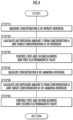
- a flow chart of the operation processes performed by the control device body 401 of the control system 400 shall be described next with reference to FIG. 4 .
- the concentration A of nitrate nitrogen in the second-half region of the first-half aerobic region 206 is measured by the first detection device 403 (STEP10).
- the air diffusion amount C is then calculated from a target concentration A1 of nitrate nitrogen required for realizing a target denitrification amount (concentration) and the concentration A of nitrate nitrogen in the second-half region of the first-half aerobic region 206 (STEP20).
- the concentration A and the target concentration A1 of nitrate nitrogen are compared, and the air diffusion amount C in the first-half aerobic region 206 and the first-half combined-use region 209f is established using, e.g., formula 1 below so that the concentration A of nitrate nitrogen when the wastewater has passed through the first-half aerobic region 206 reaches the target concentration A1 of nitrogen.
- C P ⁇ A1 ⁇ A
- P is a coefficient established from the relationship between the air diffusion amount and the nitrification speed in the first-half aerobic region 206 and can be empirically established in advance.
- P can be calculated using a plurality of parameters p1, p2, p3, ... that are established according to the water temperature, the total nitrogen (T-N) load amount in the wastewater, the hydraulic retention time (HRT), and other treatment conditions.
- the optimal numeric values for the parameters p1, p2, p3, ... can be determined using the machine learning DB 401b described above.
- the outputs of the first and second blowers 301, 302 and the opening degree of the first electric valve 304 are controlled so that the air diffusion amount in the first-half aerobic region 206 and the first-half combined-use region 209f reaches the air diffusion amount C (STEP30).
- the concentration B of ammonia nitrogen in the second-half region of the second-half aerobic region 208 is measured by the second detection device 404 (STEP40).
- the air diffusion amount D is then calculated from the concentration B of ammonia nitrogen in the second-half region of the second-half aerobic region 208 and a target concentration B1 of ammonia nitrogen permitted to remain in the treated liquid flowing out through the second-half aerobic region 208 (STEP50).
- the concentration B and the target concentration B1 of ammonia nitrogen are compared, and the air diffusion amount D in the second-half aerobic region 208 and the second-half combined-use region 209b is established using, e.g., formula 2 below so that the concentration of ammonia nitrogen in the treated water that has passed through the second-half aerobic region 208 falls to or below the target concentration B1 of ammonia nitrogen.
- D Q ⁇ B ⁇ B1
- Q is a coefficient established from the relationship between the air diffusion amount and the nitrification speed in the second-half aerobic region 208 and can be empirically established in advance.
- Q can be calculated using a plurality of parameters q1, q2, q3, ... that are established according to the water temperature, the total nitrogen (T-N) load amount in the wastewater, the hydraulic retention time (HRT), and other treatment conditions.
- the optimal numeric values for the parameters q1, q2, q3, ... considering external factors can be determined using the machine learning DB 401b described above.
- the outputs of the first and second blowers 301, 302 and the opening degree of the second electric valve 305 are controlled so that the air diffusion amount in the second-half aerobic region 208 and the second-half combined-use region 209b reaches the air diffusion amount D (STEP60).
- the series of operation processes performed by the control device body 401 then ends. However, by repeatedly performing the processes described above, the control device body 401 can carry out desired air diffusion in each region of the tank 200.
- a nitrification and denitrification method using the treatment apparatus 100 according to the present disclosure shall be described next.
- the sewage or other form of wastewater is introduced into the anaerobic region 205 through the initial precipitation reservoir (not shown).
- the returned sludge which is returned from a sludge collection part (not shown), is also introduced together with the wastewater.
- the anaerobic region 205 is kept in an anaerobic state; therefore, phosphorus contained in the returned sludge is released under anaerobic conditions.
- the phosphorus is subsequently captured by microorganisms in the first-half aerobic region 206, the denitrification region 207, and the second-half aerobic region 208 and is removed from the wastewater as sludge.
- the wastewater that is treated for a prescribed period of time in the anaerobic region 205 flows through a cutout-form opening formed below the partition wall 204 and flows into the first-half aerobic region 206.
- control is carried out so as to reach the air diffusion amount established according to formula 1. Therefore, the nitrifying bacteria are activated, the ammonia nitrogen contained in the wastewater is nitrified, nitrate nitrogen is produced, and the concentration of nitrate nitrogen rises.
- the concentration of nitrate nitrogen (NO x -N) rises from the first-half aerobic region 206 to the denitrification region 207 (denitrification region and inlet section).
- the concentration of nitrate nitrogen (NO x -N) in the denitrification region 207 reaches the target concentration A1 of nitrate nitrogen because the air diffusion amount in the first-half aerobic region 206 and the first-half combined-use region 209f is controlled according to formula 1.
- the air diffusion amount in the first-half aerobic region 206 and the first-half combined-use region 209f is controlled so as to be sufficient for reaching the target concentration A1 of nitrate nitrogen but not to be excessive.
- the wastewater that has passed through the first-half aerobic region 206 is introduced into the denitrification region 207 via the first-half combined-use region 209f.
- denitrification is performed by the denitrifying bacteria because the amount of air diffused from the air diffusion parts 306 is controlled by the control device body 401 and the oxygen-free or low-oxygen state is maintained.
- nitrate nitrogen in the concentration that has reached the target concentration A1 of nitrate nitrogen formed in the first-half aerobic region 206 is denitrified, whereby nitrogen corresponding to the target denitrification amount is removed from the wastewater.
- the wastewater that has passed through the denitrification region 207 is introduced into the second-half aerobic region 208 via the second-half combined-use region 209b.
- the ammonia nitrogen remaining in the wastewater is nitrified and becomes nitrate nitrogen because the amount of air diffused from the air diffusion parts 306 is controlled by the control device body 401 and an aerobic state is achieved again.
- the concentration of ammonia nitrogen in the wastewater that has passed through the denitrification region 207 falls to or below the target concentration B1 of ammonia nitrogen permitted to remain in the treated water because the air diffusion amount in the second-half aerobic region 208 and the second-half combined-use region 209b is controlled so as to reach the air diffusion amount established according to formula 2.
- the treated water that has passed through the second-half aerobic region 208 not only undergoes a decrease in the concentration of ammonia nitrogen but also undergoes a decrease in nitrogen concentration overall and is made even less hazardous.
- the treated water is discharged to a river or the like after chlorine disinfection or another ordinary treatment.
- the treatment apparatus 100 compares the target concentration A1 of nitrate nitrogen required for realizing the target denitrification amount (concentration) with the concentration A of nitrate nitrogen in the second-half region of the first-half aerobic region 206 and controls the air diffusion amount C in the first-half aerobic region 206 and the first-half combined-use region 209f so that the concentration of nitrate nitrogen when the wastewater has passed through the first-half aerobic region 206 reaches the target concentration A1 of nitrate nitrogen.
- nitrate nitrogen in the first-half aerobic region 206 so that a denitrification amount required for reducing the concentration of nitrogen contained in the wastewater to a prescribed value or therebelow can be ensured while maintaining the oxygen-free or low-oxygen state in the denitrification region 207.
- a denitrification amount required for reducing the concentration of nitrogen contained in the wastewater to a prescribed value or therebelow can be ensured while maintaining the oxygen-free or low-oxygen state in the denitrification region 207.
- the treatment apparatus 100 compares the concentration B of ammonia nitrogen in the second-half region of the second-half aerobic region 208 with the target concentration B1 of ammonia nitrogen permitted to remain in the treated water and controls the air diffusion amount D in the second-half aerobic region 208 and the second-half combined-use region 209b so that the concentration of ammonia nitrogen in the treated water that has passed through the second-half aerobic region 208 falls to or below the target concentration B1 of ammonia nitrogen; therefore, it is possible to reduce the concentration of ammonia nitrogen remaining in the treated water to or below the target concentration B1 of ammonia nitrogen.
- rising flows are produced by the diffused air in the first-half aerobic region 206 and the second-half aerobic region 208, as indicated by the arrows in FIG. 2 , and the water surface rises. Therefore, the pair of swirl flows described earlier are produced, and the combined-use regions 209 where both nitrification and denitrification progress are formed on the outer side of the denitrification region 207 adjacent to the first-half aerobic region 206 and on the outer side of the denitrification region 207 adjacent to the second-half aerobic region 208.
- the denitrification and denitrification method it is thereby possible, in the nitrification and denitrification method according to the present disclosure, to maintain the oxygen-free or low-oxygen state in the denitrification region 207 and to cause a denitrification reaction to progress, even if no partition wall is provided. Additionally, the denitrification treatment is carried out in the combined-use regions 209 as well as the denitrification region 207, and the nitrification treatment is also carried out in the combined-use regions 209. Therefore, the denitrification region can be expanded without reducing the size of the aerobic regions, and it is possible to increase the denitrification treatment amount that can be employed as a target at the same tank volume. It is also unnecessary to provide a partition wall to the tank 200, and it is possible to reduce equipment costs.
- the open/closed state of the manual valves 307a at the boundaries between regions is changed according to the weather or the season when the amount of wastewater to be treated or the concentration of organic matter varies, thereby making it possible to change the positions of the combined-use regions 209 and change the volume and length of the first-half aerobic region 206, the denitrification region 207, and the second-half aerobic region 208.
- the treatment apparatus 100 is also configured so that the position of the first detection device 403 can be moved in association with any change in the positions of the combined-use regions 209.
- valves that control the individual air diffusion parts 306 in the present embodiment are all manual valves 307, but it is also permissible to replace the manual valves 307a located at positions adjacent to the regions with electric valves and change the opening degrees of each of the valves, thereby making it possible to change the volume and length of the regions.
- the amount of air diffused from the air diffusion parts 306 in the denitrification region 207 can be set to 0, but a very small amount of air diffusion with which the sludge continues to be suspended in the wastewater and sedimentation is prevented is permitted. This makes it unnecessary to provide a stirring vane or the like to the anaerobic region 205 and makes it possible further reduce equipment costs.
- control device 401 executes a step for controlling the amount of air diffused from the plurality of air diffusion parts 306 of the air diffusion device 300, forming the first-half aerobic region 206, the first-half combined-use region 209f where both nitrification and denitrification progress, the denitrification region 207, the second-half combined-use region 209b where both nitrification and denitrification progress, and the second-half aerobic region 208 in the stated order from the upstream side along the flow channel 203, and furthermore producing first and second swirl flows constituting a pair in the flow channel 203.
- control device 401 controls the air diffusion amount in the first-half aerobic region 206 and the first-half combined-use region 209f on the basis of the concentration of nitrate nitrogen detected by the first detection device 403, and controls the air diffusion amount in the second-half combined-use region 209b and the second-half aerobic region 208 on the basis of the concentration of ammonia nitrogen detected by the second detection device 404.
- the first swirl flow is a flow that rises in the first-half combined-use region 209f (refer to the arrow U1), advances downstream at the water-surface side of the denitrification region 207 (refer to the arrow R1), descends near the center of the denitrification region 207 (refer to the arrow D), and advances upstream at the bottom side of the denitrification region 207 (refer to the arrow L2).
- the second swirl flow is a flow that rises in the second-half combined use region 209b (refer to the arrow U2), advances upstream at the water-surface side of the denitrification region 207 (refer to the arrow L1), descends near the center of the denitrification region 207 (refer to the arrow D), and advances downstream at the bottom side of the denitrification region 207 (refer to the arrow R2).
- a sufficient denitrification treatment amount can be obtained irrespective of the lack of any partition plate because the combined-use regions 209 serve as buffer regions and the low-oxygen state of the denitrification region 207 is maintained largely without being affected by an oxygen-rich forward flow from the first-half aerobic region 206 or an oxygen-rich backward flow from the second-half aerobic region 208. Additionally, it is possible to avoid major investments in equipment because the partition plate is unnecessary.
- the denitrification region 207 can be expanded without reducing the size of the aerobic regions, and it is possible to meet demands for increasing the denitrification treatment amount at the same tank volume or demands for reducing the tank volume while maintaining the same denitrification treatment amount, because the denitrification treatment is carried out in the combined-use regions 209 as well as the denitrification region 207 and the nitrification treatment is also carried out in the combined-use regions 209.
- the air diffusion amount in the regions pertaining to the first-half aerobic region 206 is controlled on the basis of the concentration of nitrate nitrogen measured by the first detection device 403 disposed downstream of the first-half aerobic region 206, whereby the concentration of nitrate nitrogen in the wastewater flowing into the denitrification region 207 is adjusted; and the air diffusion amount in the regions pertaining to the second-half aerobic region 208 is controlled on the basis of the concentration of ammonia nitrate measured by the second detection device 404 disposed downstream of the second-half aerobic region 208, whereby nitrification is sufficiently carried out in the second-half aerobic region 208 and the concentration of remaining ammonia nitrogen stays within a permissible range.
- the air diffusion device 300 has a plurality of openable/closable air diffusion parts 306 along the flow channel 203.
- the air diffusion device 300 is configured so that selecting the air diffusion parts 306 by which air diffusion is performed makes it possible to change the position of either of the first-half combined-use region 209f or the second-half combined-use region 209b, and is configured so that the position of either of the first detection device or the second detection device can be moved in accordance with the change in the position of the first-half combined-use region 209f or the second-half combined-use region 209b.
- the "plurality of openable/closable air diffusion parts" are assumed to be, inter alia, a plurality of air diffusion parts configured to be switched between constrained aeration and unconstrained aeration by the electric valves.
- the air diffusion parts 306 by which air diffusion is performed are selected in accordance with treatment conditions pertaining to the facility where the present disclosure is applied or variations in the wastewater load caused by variations in the weather or the season because selecting the air diffusion parts 306 by which air diffusion is performed in the air diffusion device 300 makes it possible to vary the positions of the combined-use regions 209; this makes it possible to change the positions of the combined-use regions 209 to make adjustments so that each region is set to a suitable length.
- the position of the first detection device 403 can be disposed downstream of the first-half aerobic region 206 at all times, even if the length of the first-half aerobic region 206 changes, because the air diffusion device 300 is configured so that the position of the first detection device 403 can be moved in accordance with the change in the positions of the combined-use regions 209.
- the control device 401 is configured so that: the air diffusion amount in the first-half aerobic region 206 and the first-half combined-use region 209f is controlled on the basis of the difference between the target concentration of nitrate nitrogen in the first-half aerobic region 206, which is set so that the denitrification amount required for reducing the concentration of nitrogen contained in the wastewater to a prescribed value or therebelow can be ensured in the denitrification region 207 and so that a prescribed oxygen-free or low-oxygen state can be formed in the denitrification region 207 and the concentration of nitrate nitrogen detected by the first detection device 403; and the air diffusion amount in the second-half combined-use region 209b and the second-half aerobic region 208 is controlled on the basis of the difference between the concentration of ammonia nitrogen detected by the second detection device 404 and the target concentration of ammonia nitrogen permitted to remain in the treated water.
- the air diffusion amount in regions pertaining to the first-half aerobic region 206 is controlled, on the basis of the difference between the target concentration A1 of nitrate nitrogen in the first-half aerobic region 206 and the concentration A of nitrate nitrogen detected by the first detection device 403, so that the concentration A of nitrate nitrogen approaches the target concentration A1 of nitrate nitrogen, thereby making it possible to sufficiently ensure the concentration of nitrate nitrogen in the wastewater flowing into the denitrification region 207 and to ensure the required denitrification amount.
- the air diffution amount in the regions pertaining to the second-half aerobic region 208 is controlled on the basis of the difference between the concentration B of ammonia nitrogen detected by the second detection device 404 and the target concentration B1 of ammonia nitrogen permitted to remain in the treated water, thereby making it possible to reduce the concentration of ammonia nitrogen so as to fall to or below the target concentration of ammonia nitrogen permitted to remain in the treated water.
- Sewage was treated using the treatment apparatus 100 shown in FIGS. 1 and 2 while the amount of diffusion air from the air diffusion device 300 was controlled by the control system 400.
- the result of the treatment shall be described below.
- the total nitrogen (T-N) removal rate for the treated water was 60%, and the concentration of ammonia in the treated water was able to be set to 0.0 mg N/L.
- Sewage was continuously treated using the treatment apparatus 100 shown in FIGS. 1 and 2 while the amount of diffusion air from the air diffusion device 300 was controlled by the control system 400.
- the biochemical oxygen demand (BOD) concentration, the total nitrogen (T-N) concentration, and the total phosphorus (T-P) concentration at an initial precipitation outlet and a final precipitation outlet were periodically measured, and any change in these concentrations was examined.
- the BOD concentration was measured according to the method described in " Sewage testing methods -2012 editionvolume 2, chapter 1, section 21, 1. Biochemical oxygen demand (BOD) .”
- the T-N concentration was measured according to the method described in JIS K 0170-3 on the basis of " Sewage testing methods -2012 edition- volume 1, chapter 5, section 13, Flow analysis .”
- the T-P concentration was measured according to the method described in JIS K 0170-4 on the basis of " Sewage testing methods -2012 edition- volume 1, chapter 5, section 13, Flow analysis.
- a testing operation was carried out continuously for one year or longer to conduct measurement.
- the measurement results for the BOD concentration are shown in FIG. 5
- the measurement results for the T-N concentration are shown in FIG. 6
- the measurement results for the T-P concentration are shown in FIG. 7 .
- the dashed lines in the drawings represent respective target reduction values.
- the nitrification and denitrification method using the treatment apparatus 100 according to the present invention makes it possible to reduce BOD, T-N, and T-P stably over one year or more.
Landscapes
- Life Sciences & Earth Sciences (AREA)
- Biodiversity & Conservation Biology (AREA)
- Microbiology (AREA)
- Hydrology & Water Resources (AREA)
- Engineering & Computer Science (AREA)
- Environmental & Geological Engineering (AREA)
- Water Supply & Treatment (AREA)
- Chemical & Material Sciences (AREA)
- Organic Chemistry (AREA)
- Health & Medical Sciences (AREA)
- Molecular Biology (AREA)
- Purification Treatments By Anaerobic Or Anaerobic And Aerobic Bacteria Or Animals (AREA)
Applications Claiming Priority (2)
| Application Number | Priority Date | Filing Date | Title |
|---|---|---|---|
| JP2022014551 | 2022-02-01 | ||
| PCT/JP2023/003056 WO2023149425A1 (ja) | 2022-02-01 | 2023-01-31 | 排水処理装置、及び排水処理方法 |
Publications (2)
| Publication Number | Publication Date |
|---|---|
| EP4458779A1 true EP4458779A1 (de) | 2024-11-06 |
| EP4458779A4 EP4458779A4 (de) | 2025-11-26 |
Family
ID=87552450
Family Applications (1)
| Application Number | Title | Priority Date | Filing Date |
|---|---|---|---|
| EP23749741.7A Pending EP4458779A4 (de) | 2022-02-01 | 2023-01-31 | Abwasserbehandlungsvorrichtung und abwasserbehandlungsverfahren |
Country Status (8)
| Country | Link |
|---|---|
| US (1) | US20250197264A1 (de) |
| EP (1) | EP4458779A4 (de) |
| JP (1) | JP7777156B2 (de) |
| KR (1) | KR20240122838A (de) |
| CN (1) | CN118613451A (de) |
| AU (1) | AU2023216578B2 (de) |
| CA (1) | CA3243394A1 (de) |
| WO (1) | WO2023149425A1 (de) |
Family Cites Families (13)
| Publication number | Priority date | Publication date | Assignee | Title |
|---|---|---|---|---|
| JPH08318290A (ja) * | 1995-05-23 | 1996-12-03 | Ebara Corp | 汚水の好気性処理槽及び処理方法 |
| JP2008221162A (ja) | 2007-03-14 | 2008-09-25 | Kobelco Eco-Solutions Co Ltd | 脱窒処理槽および脱窒処理方法 |
| EP2824080A4 (de) * | 2012-03-09 | 2015-10-28 | Metawater Co Ltd | Abwasserverarbeitungsvorrichtung, abwasserverarbeitungsverfahren, abwasserverarbeitungssystem, steuerungsvorrichtung, steuerungsverfahren und programm |
| CA2866996C (en) * | 2012-03-09 | 2019-09-10 | Metawater Co., Ltd. | Wastewater treatment apparatus, wastewater treatment method, wastewater treatment system, control device, control method, and program |
| HK1212669A1 (zh) * | 2012-09-13 | 2016-06-17 | D.C. Water & Sewer Authority | 用於在废水处理中脱除氮的方法和装置 |
| RU2671729C2 (ru) * | 2013-03-14 | 2018-11-06 | Ди.Си. УОТЕР ЭНД СЬЮЭР ОТОРИТИ | Способ и система для удаления азота из сточных вод |
| JP6062328B2 (ja) * | 2013-07-10 | 2017-01-18 | メタウォーター株式会社 | 排水の処理方法および排水の処理装置、並びに制御方法、制御装置、およびプログラム |
| JP6422639B2 (ja) * | 2013-09-10 | 2018-11-14 | メタウォーター株式会社 | 排水の処理装置、排水の処理方法、および排水の処理システム、並びに制御装置、およびプログラム |
| FR3012444B1 (fr) | 2013-10-30 | 2016-01-01 | Degremont | Procede et installation de traitement biologique d'effluent, en particulier d'eaux residuaires |
| JP6158691B2 (ja) * | 2013-11-18 | 2017-07-05 | 株式会社東芝 | 有機排水処理装置、有機排水の処理方法及び有機排水処理装置の制御プログラム |
| JP7166058B2 (ja) * | 2018-02-09 | 2022-11-07 | オルガノ株式会社 | 水処理方法および水処理装置 |
| JP7002977B2 (ja) | 2018-03-27 | 2022-02-10 | 株式会社九電工 | 排水処理装置 |
| JP7158912B2 (ja) | 2018-06-22 | 2022-10-24 | 株式会社東芝 | 調整区画制御装置、調整区画制御方法、コンピュータプログラム及び有機排水処理システム |
-
2023
- 2023-01-31 JP JP2023578561A patent/JP7777156B2/ja active Active
- 2023-01-31 CN CN202380018834.2A patent/CN118613451A/zh active Pending
- 2023-01-31 AU AU2023216578A patent/AU2023216578B2/en active Active
- 2023-01-31 WO PCT/JP2023/003056 patent/WO2023149425A1/ja not_active Ceased
- 2023-01-31 KR KR1020247023187A patent/KR20240122838A/ko active Pending
- 2023-01-31 CA CA3243394A patent/CA3243394A1/en active Pending
- 2023-01-31 US US18/834,140 patent/US20250197264A1/en active Pending
- 2023-01-31 EP EP23749741.7A patent/EP4458779A4/de active Pending
Also Published As
| Publication number | Publication date |
|---|---|
| EP4458779A4 (de) | 2025-11-26 |
| CA3243394A1 (en) | 2025-01-20 |
| JP7777156B2 (ja) | 2025-11-27 |
| US20250197264A1 (en) | 2025-06-19 |
| KR20240122838A (ko) | 2024-08-13 |
| CN118613451A (zh) | 2024-09-06 |
| AU2023216578B2 (en) | 2026-01-08 |
| AU2023216578A1 (en) | 2024-08-15 |
| WO2023149425A1 (ja) | 2023-08-10 |
| JPWO2023149425A1 (de) | 2023-08-10 |
Similar Documents
| Publication | Publication Date | Title |
|---|---|---|
| US9475715B2 (en) | Optimized process and aeration performance with an advanced control algorithm | |
| JP3961835B2 (ja) | 下水処理場水質制御装置 | |
| JP2001252691A (ja) | 下水処理場の水質制御装置 | |
| JP2010269254A (ja) | 水処理設備 | |
| JP2012200705A (ja) | 窒素含有排水の処理方法及び装置 | |
| JP4229999B2 (ja) | 生物学的窒素除去装置 | |
| JP7158912B2 (ja) | 調整区画制御装置、調整区画制御方法、コンピュータプログラム及び有機排水処理システム | |
| Maslak | Sequencing batch reactor treatment of tannery wastewater for carbon and nitrogen removal | |
| JP5714355B2 (ja) | 活性汚泥処理装置及びその処理方法 | |
| EP4458779A1 (de) | Abwasserbehandlungsvorrichtung und abwasserbehandlungsverfahren | |
| van Kempen et al. | SHARON process evaluated for improved wastewater treatment plant nitrogen effluent quality | |
| JP6375257B2 (ja) | 水処理装置 | |
| Carrio et al. | Practical considerations for design of a step-feed biological nutrient removal system | |
| Bury et al. | Dynamic simulation of chemical industry wastewater treatment plants | |
| Galarza et al. | Application of mathematical tools to improve the design and operation of activated sludge plants. Case study: The new WWTP of Galindo-Bilbao Part II: Operational strategies and automatic controllers | |
| JPH0938682A (ja) | 生物学的水処理方法 | |
| JP3708752B2 (ja) | 硝酸態窒素生物処理方法および装置 | |
| JP6430324B2 (ja) | 排水の処理方法および排水の処理装置 | |
| Roman | Aeration control of nitrification process based on the ammonium concentration in the aeration tank | |
| Kayser | New German design guideline for single stage activated sludge plants | |
| Van Hulle et al. | Practical experiences with start-up and operation of a continously aerated lab-scale SHARON reactor | |
| JP2000293223A (ja) | 監視制御装置 | |
| KR101962566B1 (ko) | 연속회분식 반응조를 활용한 저 에너지 혐기성 암모늄 산화 시스템 및 이 시스템을 위한 선행 스케줄링 방법 | |
| Bowden et al. | Evaluation of the single sludge deammonification process for the treatment of plant recycle streams containing a high ammonium concentration | |
| Kincheloe et al. | DEVELOPMENT OF A BASIS OF DESIGN FOR FULL SCALE EQUIPMENT USING RESEARCH TESTING RESULTS AND A PROCESS MODEL |
Legal Events
| Date | Code | Title | Description |
|---|---|---|---|
| STAA | Information on the status of an ep patent application or granted ep patent |
Free format text: STATUS: THE INTERNATIONAL PUBLICATION HAS BEEN MADE |
|
| PUAI | Public reference made under article 153(3) epc to a published international application that has entered the european phase |
Free format text: ORIGINAL CODE: 0009012 |
|
| STAA | Information on the status of an ep patent application or granted ep patent |
Free format text: STATUS: REQUEST FOR EXAMINATION WAS MADE |
|
| 17P | Request for examination filed |
Effective date: 20240801 |
|
| AK | Designated contracting states |
Kind code of ref document: A1 Designated state(s): AL AT BE BG CH CY CZ DE DK EE ES FI FR GB GR HR HU IE IS IT LI LT LU LV MC ME MK MT NL NO PL PT RO RS SE SI SK SM TR |
|
| DAV | Request for validation of the european patent (deleted) | ||
| DAX | Request for extension of the european patent (deleted) | ||
| A4 | Supplementary search report drawn up and despatched |
Effective date: 20251028 |
|
| RIC1 | Information provided on ipc code assigned before grant |
Ipc: C02F 3/34 20230101AFI20251022BHEP |