EP4458480A1 - Vollautomatisches objektzufuhrsystem für ein querbandsortiersystem - Google Patents
Vollautomatisches objektzufuhrsystem für ein querbandsortiersystem Download PDFInfo
- Publication number
- EP4458480A1 EP4458480A1 EP22914116.3A EP22914116A EP4458480A1 EP 4458480 A1 EP4458480 A1 EP 4458480A1 EP 22914116 A EP22914116 A EP 22914116A EP 4458480 A1 EP4458480 A1 EP 4458480A1
- Authority
- EP
- European Patent Office
- Prior art keywords
- section
- conveying section
- conveying
- belt
- roller
- Prior art date
- Legal status (The legal status is an assumption and is not a legal conclusion. Google has not performed a legal analysis and makes no representation as to the accuracy of the status listed.)
- Pending
Links
Images




Classifications
-
- B—PERFORMING OPERATIONS; TRANSPORTING
- B07—SEPARATING SOLIDS FROM SOLIDS; SORTING
- B07C—POSTAL SORTING; SORTING INDIVIDUAL ARTICLES, OR BULK MATERIAL FIT TO BE SORTED PIECE-MEAL, e.g. BY PICKING
- B07C5/00—Sorting according to a characteristic or feature of the articles or material being sorted, e.g. by control effected by devices which detect or measure such characteristic or feature; Sorting by manually actuated devices, e.g. switches
- B07C5/36—Sorting apparatus characterised by the means used for distribution
-
- B—PERFORMING OPERATIONS; TRANSPORTING
- B07—SEPARATING SOLIDS FROM SOLIDS; SORTING
- B07C—POSTAL SORTING; SORTING INDIVIDUAL ARTICLES, OR BULK MATERIAL FIT TO BE SORTED PIECE-MEAL, e.g. BY PICKING
- B07C5/00—Sorting according to a characteristic or feature of the articles or material being sorted, e.g. by control effected by devices which detect or measure such characteristic or feature; Sorting by manually actuated devices, e.g. switches
- B07C5/02—Measures preceding sorting, e.g. arranging articles in a stream orientating
-
- B—PERFORMING OPERATIONS; TRANSPORTING
- B65—CONVEYING; PACKING; STORING; HANDLING THIN OR FILAMENTARY MATERIAL
- B65G—TRANSPORT OR STORAGE DEVICES, e.g. CONVEYORS FOR LOADING OR TIPPING, SHOP CONVEYOR SYSTEMS OR PNEUMATIC TUBE CONVEYORS
- B65G47/00—Article or material-handling devices associated with conveyors; Methods employing such devices
- B65G47/02—Devices for feeding articles or materials to conveyors
- B65G47/04—Devices for feeding articles or materials to conveyors for feeding articles
- B65G47/12—Devices for feeding articles or materials to conveyors for feeding articles from disorderly-arranged article piles or from loose assemblages of articles
-
- B—PERFORMING OPERATIONS; TRANSPORTING
- B65—CONVEYING; PACKING; STORING; HANDLING THIN OR FILAMENTARY MATERIAL
- B65G—TRANSPORT OR STORAGE DEVICES, e.g. CONVEYORS FOR LOADING OR TIPPING, SHOP CONVEYOR SYSTEMS OR PNEUMATIC TUBE CONVEYORS
- B65G47/00—Article or material-handling devices associated with conveyors; Methods employing such devices
- B65G47/02—Devices for feeding articles or materials to conveyors
- B65G47/04—Devices for feeding articles or materials to conveyors for feeding articles
- B65G47/12—Devices for feeding articles or materials to conveyors for feeding articles from disorderly-arranged article piles or from loose assemblages of articles
- B65G47/14—Devices for feeding articles or materials to conveyors for feeding articles from disorderly-arranged article piles or from loose assemblages of articles arranging or orientating the articles by mechanical or pneumatic means during feeding
-
- B—PERFORMING OPERATIONS; TRANSPORTING
- B65—CONVEYING; PACKING; STORING; HANDLING THIN OR FILAMENTARY MATERIAL
- B65G—TRANSPORT OR STORAGE DEVICES, e.g. CONVEYORS FOR LOADING OR TIPPING, SHOP CONVEYOR SYSTEMS OR PNEUMATIC TUBE CONVEYORS
- B65G47/00—Article or material-handling devices associated with conveyors; Methods employing such devices
- B65G47/22—Devices influencing the relative position or the attitude of articles during transit by conveyors
- B65G47/26—Devices influencing the relative position or the attitude of articles during transit by conveyors arranging the articles, e.g. varying spacing between individual articles
- B65G47/28—Devices influencing the relative position or the attitude of articles during transit by conveyors arranging the articles, e.g. varying spacing between individual articles during transit by a single conveyor
-
- B—PERFORMING OPERATIONS; TRANSPORTING
- B65—CONVEYING; PACKING; STORING; HANDLING THIN OR FILAMENTARY MATERIAL
- B65G—TRANSPORT OR STORAGE DEVICES, e.g. CONVEYORS FOR LOADING OR TIPPING, SHOP CONVEYOR SYSTEMS OR PNEUMATIC TUBE CONVEYORS
- B65G47/00—Article or material-handling devices associated with conveyors; Methods employing such devices
- B65G47/52—Devices for transferring articles or materials between conveyors i.e. discharging or feeding devices
- B65G47/68—Devices for transferring articles or materials between conveyors i.e. discharging or feeding devices adapted to receive articles arriving in one layer from one conveyor lane and to transfer them in individual layers to more than one conveyor lane or to one broader conveyor lane, or vice versa, e.g. combining the flows of articles conveyed by more than one conveyor
-
- B—PERFORMING OPERATIONS; TRANSPORTING
- B65—CONVEYING; PACKING; STORING; HANDLING THIN OR FILAMENTARY MATERIAL
- B65G—TRANSPORT OR STORAGE DEVICES, e.g. CONVEYORS FOR LOADING OR TIPPING, SHOP CONVEYOR SYSTEMS OR PNEUMATIC TUBE CONVEYORS
- B65G47/00—Article or material-handling devices associated with conveyors; Methods employing such devices
- B65G47/52—Devices for transferring articles or materials between conveyors i.e. discharging or feeding devices
- B65G47/68—Devices for transferring articles or materials between conveyors i.e. discharging or feeding devices adapted to receive articles arriving in one layer from one conveyor lane and to transfer them in individual layers to more than one conveyor lane or to one broader conveyor lane, or vice versa, e.g. combining the flows of articles conveyed by more than one conveyor
- B65G47/71—Devices for transferring articles or materials between conveyors i.e. discharging or feeding devices adapted to receive articles arriving in one layer from one conveyor lane and to transfer them in individual layers to more than one conveyor lane or to one broader conveyor lane, or vice versa, e.g. combining the flows of articles conveyed by more than one conveyor the articles being discharged or distributed to several distinct separate conveyors or to a broader conveyor lane
-
- B—PERFORMING OPERATIONS; TRANSPORTING
- B65—CONVEYING; PACKING; STORING; HANDLING THIN OR FILAMENTARY MATERIAL
- B65G—TRANSPORT OR STORAGE DEVICES, e.g. CONVEYORS FOR LOADING OR TIPPING, SHOP CONVEYOR SYSTEMS OR PNEUMATIC TUBE CONVEYORS
- B65G47/00—Article or material-handling devices associated with conveyors; Methods employing such devices
- B65G47/74—Feeding, transfer, or discharging devices of particular kinds or types
- B65G47/94—Devices for flexing or tilting travelling structures; Throw-off carriages
- B65G47/96—Devices for tilting links or platform
-
- Y—GENERAL TAGGING OF NEW TECHNOLOGICAL DEVELOPMENTS; GENERAL TAGGING OF CROSS-SECTIONAL TECHNOLOGIES SPANNING OVER SEVERAL SECTIONS OF THE IPC; TECHNICAL SUBJECTS COVERED BY FORMER USPC CROSS-REFERENCE ART COLLECTIONS [XRACs] AND DIGESTS
- Y02—TECHNOLOGIES OR APPLICATIONS FOR MITIGATION OR ADAPTATION AGAINST CLIMATE CHANGE
- Y02W—CLIMATE CHANGE MITIGATION TECHNOLOGIES RELATED TO WASTEWATER TREATMENT OR WASTE MANAGEMENT
- Y02W30/00—Technologies for solid waste management
- Y02W30/50—Reuse, recycling or recovery technologies
- Y02W30/62—Plastics recycling; Rubber recycling
Definitions
- the present invention relates to the technical field of sorting equipment, and in particular to a fully automatic object supply system for a cross-belt sorting system.
- a fully automatic object supply system for a cross-belt sorting system is provided in the present invention, which can make full use of the efficiency of the cross-belt sorting system, improves the sorting efficiency, and reduces the labor intensity and the labor costs.
- the fully automatic object supply system comprises a belt conveyor, a spiral unpacking chute is arranged at a feeding end of the belt conveyor, a stacked-objects separating device, a scattering device, a single-object separation device, a roller centering machine, a seesawing belt conveyor, a stacked-objects detecting device, an arriving-object detecting device, and a balance wheel sorting machine are sequentially arranged on the belt conveyor along a conveying direction, the balance wheel sorting machine is arranged at a tail section of a discharging end of the belt conveyor, and one or more balance wheel sorting machines are provided, one side of the balance wheel sorting machine is connected at a feeding end of the four-section automatic package supply machine, a feeding end of a return chute is connected at the discharging end of the belt conveyor, and a discharging end of the return chute is connected at a feeding end of the three-section semi-automatic package supply machine.
- a special-shaped object chute is arranged on one side of the feeding end of the belt conveyor, special-shaped objects are removed and put into the special-shaped object chute after manual unpacking.
- the stacked-objects separating device includes a scattering section, a temporary storage section, a separating section and a transition section that are sequentially arranged along the conveying direction
- the scattering section is a roller scattering chute arranged obliquely
- a position of a feeding end of the scattering section is higher than a position of a discharging end of the scattering section
- the temporary storage section is a belt conveying mechanism arranged horizontally
- the separating section includes a first climbing conveying section and a second climbing conveying section sequentially arranged along the conveying direction, the first climbing conveying section and the second climbing conveying section are arranged obliquely, a position of a feeding end of the first climbing conveying section is lower than a position of a discharging end of the first climbing conveying section, a position of a feeding end of the second climbing conveying section is lower than a position of a discharging end of the second climbing conveying section, and an inclined angle of the first climbing conveying section is greater than an
- an inclined angle of the scattering section ranges from 20° to 32°, and two sets of unpowered rollers are arranged on the scattering section in a V shape.
- side baffles are arranged on left and right sides of the temporary storage section, the first climbing conveying section, the second climbing conveying section, the descending conveying section and the horizontal conveying section, respectively, a first baffle is arranged at a gap position between the side baffle of the temporary storage section and the side baffle of the first climbing conveying section, a second baffle is arranged at a gap position between the side baffle of the first climbing conveying section and the side baffle of the second climbing conveying section, a third baffle is arranged at a gap position between the side baffle of the second climbing conveying section and the side baffle of the descending conveying section, and a fourth baffle is arranged at a gap position between the side baffle of the descending conveying section and the side baffle of the horizontal conveying section, the first baffle, the second baffle, the third baffle and the fourth baffle are capable of preventing the rollers from winding objects, cameras are arranged directly above conveying passages of the scattering section, the temporary storage section, the separating
- an the four-section fully automatic package supply machine includes a first temporary storage conveying section, a second temporary conveying section, a third temporary storage conveying section sequentially arranged along the conveying direction, the first temporary storage conveying section and the second temporary storage conveying section are both servo power belt transmission structures, and the third temporary storage conveying section is an electric roller narrow-belt transmission structure, a first detecting light curtain is cross-arranged above a feeding end of the first temporary storage conveying section, the first detecting light curtain is arranged on a first detecting light curtain bracket, both ends of the first detecting light curtain bracket are fixed on left and right sides of the first temporary storage conveying section, a second detecting light curtain and a third detecting light curtain are cross-arranged above the feeding end and the discharging end of the second temporary storage conveying section, respectively, and the second detecting light curtain and the third detecting light curtain are both arranged on a second detecting light curtain bracket, both ends of the second detecting light curtain bracket are fixed on left and right sides of the second temporary storage conveying section,
- a posture adjustment device is arranged at the feeding end of the four-section fully automatic package supply machine, and the posture adjustment device includes an installation frame, and a plurality of rubber-coated rollers parallel to each other are arranged on an upper surface of the installation frame along a diagonal line, a rubber-coated roller located at an intermediate position of the plurality of rubber-coated rollers is a longest one, a length of the rubber-coated rollers in the plurality of rubber-coated rollers decreases from the intermediate position to left and right sides, side baffles and side installation frames are arranged on left and right sides of the upper end surface of the installation frame, respectively, a first side driving roller and a second side driving roller are rotatably connected at front and rear ends of the installation frame, respectively, a side driving belt is sleeved and arranged on the first side driving roller and the second side driving roller, rolling end surfaces of the plurality of rubber-coated rollers face towards one side of the side driving belt, a light curtain is cross-arranged directly above the plurality
- the three-section semi-automatic package supply machine includes a first conveying section, a second conveying section and a third conveying section sequentially arranged along the conveying direction, the first conveying section and the second conveying section are both servo power belt transmission structures, and the third conveying section is an electric roller narrow-belt transmission structure.
- side branch belt conveyor is arranged on one side of the belt conveyor side by side
- the spiral unpacking chute is arranged at a feeding end of the side branch belt conveyor
- the stacked-objects separating device, the scattering device, the single-object separating device, the roller centering machine, the seesawing belt conveyor, the stacked-objects detecting device, the arriving-object detecting device and the balance wheel sorting machine are sequentially arranged on the side branch belt conveyor along the conveying direction
- the balance wheel sorting machine is arranged at a tail section of a discharging end of the side branch belt conveyor
- one or more balance wheel sorting machines are provided
- the discharging end of the side branch belt conveyor is connected to a feeding end of a re-sorting conveyor
- the discharging end of the re-sorting conveyor is connected to the belt conveyor
- the discharging end of the re-sorting machine is located at an upstream position of the stacked-objects separating device arranged on the belt conveyor.
- the present invention effectively solves the problems of the high labor intensity and the labor costs, can make full use of the efficiency of the cross-belt sorting system, improves the sorting efficiency, reduces the labor intensity and the labor cost, and greatly guarantees that the efficiency of the sorting system can be fully utilized.
- the modular design of the single machine can implement the rapid replacement and maintenance, which greatly improves the maintainability of the equipment.
- Fourth detecting light curtain 12.16. Fifth detecting light curtain; 12.17. Sixth detecting light curtain; 13. Return chute; 14. Three-section semi-automatic package supply machine; 14.1. First conveying section; 14.2. Second conveying section; 14.3. Third conveying section; 15. Special-shaped object chute; 16. Side branch belt conveyor; 17. Re-sorting conveyor.
- the fully automatic object supply system for a cross-belt sorting system
- the fully automatic object supply system includes a belt conveyor 2.
- a spiral unpacking chute 1 is arranged at a feeding end of the belt conveyor 2.
- the packages are poured into the spiral unpacking chute 1, and then flow into the belt conveyor 2.
- a special-shaped object chute 15 is arranged on one side of the feeding end of the belt conveyor 2, and after manual unpacking, the special-shaped objects are removed and put into the special-shaped object chute 15.
- a stacked-objects separating device 3 a scattering device 4, a single-object separating device 5, a roller centering machine 6, a seesawing belt conveyor 7, a stacked-objects detecting device 8, an arriving-object detecting device 9 and a balance wheel sorting machine 10 are sequentially arranged on the belt conveyor 2 along a conveying direction.
- the stacked packages are conveyed to the stacked-objects separating device 3 by the belt conveyor 2, and the stacked-objects separating device 3 can separate the stacked packages into multi-rows of individual packages.
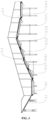
- the stacked-objects separating device 3 includes a scattering section 3.1, a temporary storage section 3.2, a separating section 3.3 and a transition section 3.4 sequentially arranged along the conveying direction.
- the scattering section 3.1 is a roller scattering chute arranged obliquely. A position of the feeding end of the scattering section 3.1 is higher than a position of the discharging end of the scattering chute 3.1.
- the temporary storage section 3.2 is a belt conveying mechanism arranged horizontally.
- the separating section 3.3 includes a first climbing conveying section 3.3.1 and a second climbing conveying section 3.3.2 sequentially arranged along the conveying direction, and the first climbing conveying section 3.3.1 and the second climbing conveying section 3.3.2 are arranged obliquely, a position of the feeding end of the first climbing conveying section 3.3.1 is lower than a position of the discharging end of the first climbing section 3.3.1, a position of the feeding end of the second climbing conveying section 3.3.2 is lower than a position of the discharging end of the second climbing section 3.3.2.
- An inclined angle of the first climbing conveying section is greater than an inclined angle of the second climbing conveying section 3.3.2.
- the first climbing conveying section 3.3.1 includes two belt conveying mechanisms arranged along the conveying direction
- the second climbing conveying section 3.3.2 includes two belt conveying mechanisms arranged along the conveying direction.
- the transition section 3.4 includes a descending conveying section 3.4.1 and a horizontal conveying section 3.4.2 sequentially arranged along the conveying direction.
- the descending conveying section 3.4.1 is a belt conveying mechanism arranged obliquely, and a position of the feeding end of the descending conveying section 3.4.1 is higher than a position of the discharging end of the descending conveying section 3.4.1.
- the horizontal conveying section 3.4.2 is a belt conveying mechanism arranged horizontally.
- the conveying end surface of the discharging end of the scattering section 3.1 is connected to the conveying end surface of the feeding end of the temporary storage section 3.2.
- the end surface of the roller at the discharging end of the first climbing conveying section 3.3.1 is tangent to the end surface of the roller at the feeding end of the second climbing conveying section 3.3.2, and a highest position of the roller at the discharging end of the first climbing conveying section 3.3.1 is higher than a highest position of the roller at the feeding end of the second climbing conveying section 3.3.2.
- the end surface of the roller at the discharging end of the second climbing conveying section 3.3.2 is tangent to the end surface of the roller at the feeding end of the descending conveying section 3.4.1, the highest position of the roller at the discharging end of the second climbing conveying section 3.3.2 is higher than the highest position of the roller at the feeding end of the descending conveying section 3.4.1.
- the end face of the roller at the discharging end of the descending conveying section 3.4.1 is tangent to the end surface of the roller at the feeding end of the horizontal conveying section 3.4.2, and a highest position of the end surface of the roller at the discharging end of the descending conveying section 3.4.1 is higher than the end surface of the roller at the feeding end of the horizontal conveying section 3.4.2.
- the inclined angle of the scattering section 3.1 ranges from 20° to 32°, and two sets of unpowered rollers are arranged on the scattering section 3.1 in a V-shape.
- the side baffles are arranged on left and right sides of the temporary storage section 3.2, the first climbing conveying section 3.3.1, the second climbing conveying section 3.3.2, the descending conveying section 3.4.1 and the horizontal conveying section 3.4.2, respectively.
- a first baffle 3.5 is arranged at a gap position between the side baffle of the temporary storage section 3.2 and the side baffle of the first climbing conveying section 3.3.1
- a second baffle 3.6 is arranged at a gap position between the side baffle of the first climbing conveying section 3.3.1 and the side baffle of the second climbing conveying section 3.3.2
- a third baffle 3.7 is arranged at a gap position between the side baffle of the second climbing conveying section 3.3.2 and the side baffle of the descending conveying section 3.4.1
- a fourth baffle 3.8 is arranged at a gap position between the side baffle of the descending conveying section 3.4.1 and the side baffle of the horizontal conveying section 3.4.2.
- the first baffle 3.5, the second baffle 3.6, the third baffle 3.7 and the fourth baffle 3.8 are capable of preventing the roller from winding the packages.
- cameras are arranged directly above the conveying passages of the scattering section 3.1, the temporary storage section 3.2, the separating section 3.3 and the transition section 3.4, respectively, and the cameras are capable of monitoring the situations of the packages in the conveying passages.
- the operating principle of the stacked-objects separating device 3 is as follows.
- the roller chute of the scattering section 3.1 plays a preliminary separation role, and the packages are evenly spread towards both sides after passing through the unpowered rollers arranged in a V-shape.
- the preliminarily separated packages are conveyed to the temporary storage section 3.2, and are ready to be conveyed to the separating section 3.3.
- the first climbing conveying section 3.3.1 of the separating section 3.3 plays a secondary separation role, some of the packages located on an upper part of the stacked packages are slid downwards due to the angles of the first climbing conveying section 3.3.1, and since a velocity difference is generated between the two conveying mechanisms at the front and rear of the first climbing conveying section 3.3.1, the stacking degree of the packages is to be further relieved.
- the second climbing conveying section 3.3.2 of the separating section 3.3 plays a third separation role, through the first two separations, the remaining stacked packages are completely separated caused by the velocity difference between the two belt conveying mechanisms at the front and rear of the second climbing section 3.3.2.
- the descending slope of the transitional section 3.4 is configured to compensate, a leap of a certain arc is produced by the packages after passing through the second climbing conveying section 3.3.2 with a high velocity, so that a small number of possible stacked objects pressed by heavy objects and difficult to be handled are fallen off and then scattered.
- the balance wheel sorting machine 10 is arranged at a tail section of the discharging end of the belt conveyor 2, and one or more balance wheel sorting machine are provided.
- one side of the balance wheel sorting machine 10 is connected at the feeding end of the four-section automatic package supply machine 12.
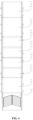
- the four-section fully automatic package supply machine 12 includes a first temporary storage conveying section 12.1, a second temporary storing conveying section 12.2 and a third temporary storing conveying section 12.3 that are sequentially arranged along the conveying direction.
- Both the temporary storage conveying section 12.1 and the second temporary storing conveying section 12.2 are the servo power belt transmission structures, and the third temporary storage conveying section 12.3 is the electric roller narrow-belt transmission structure.
- the first detecting light curtain 12.4 is cross-arranged above the feeding end of the first temporary storage conveying section 12.1, the first detecting light curtain 12.4 is arranged on the first detecting light curtain bracket 12.5, and both ends of the first detecting light curtain bracket 12.5 are fixed on the left and right sides of the first temporary storage conveying section 12.1, respectively.
- a second detecting light curtain 12.7 and a third detecting light curtain 12.8 are cross-arranged above the feeding end and the discharging end of the second temporary storage conveying section 12.2, respectively.
- the second detecting light curtain 12.7 and the third detecting light curtain 12.8 are arranged on the second detecting light curtain bracket 12.6, and both ends of the second detecting light curtain bracket 12.6 are fixed on the left and right sides of the second temporary storage conveying section 12.2, respectively.
- a transition section 12.9 is arranged at the discharging end of the third temporary storage conveying section 12.3.
- a first package supply conveying section 12.10 is arranged at the discharging end of the transition section 12.9
- a second package supply conveying section 12.11 is arranged at the discharging end of the first package supply conveying section 12.10
- a third package supply conveying section 12.12 is arranged at the discharging end of the second package supply conveying section 12.11
- a fourth package supply conveying section 12.13 is arranged at the discharging end of the third package supply conveying section 12.12.
- the transition section 12.9, the first package supply conveying section 12.10, the second package supply conveying section 12.11 and the third package supply conveying section 12.12 are all the servo power belt transmission structures, and the fourth package supply conveying section 12.13 is the electric roller narrow-belt transmission structure.
- the fourth detecting light curtain 12.15 is cross-arranged directly above the feeding end of the first package conveying section 12.10, and the fifth detecting light curtain 12.16 and the sixth detecting light curtain 12.17 are cross-arranged directly above the feeding end and the discharging end of the second package conveying section 12.11, respectively.
- the fourth detecting light curtain 12.15, the fifth detecting light curtain 12.16 and the sixth detecting light curtain 12.17 are all arranged on the third detecting light curtain bracket 12.14, and both ends of the third detecting light curtain bracket 12.14 are fixed on the left and right sides of the second package supply conveying section 12.11, respectively.
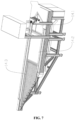
- a posture adjustment device 11 is provided at the feeding end of the four-section automatic supply machine 12.
- the posture adjustment device 11 includes an installation frame 11.1, a plurality of rubber-coated rollers 11.2 parallel to each other are sequentially arranged on an upper end surface of the installation frame 11.1 along a diagonal line.
- a rubber-coated roller 11.2 located at an intermediate position of the plurality of the rubber-coated rollers 11.2 is a longest one, and the length of the rubber-coated roller 11.2 in the plurality of rubber-coated rollers (11.2) decreases from the intermediate position to the left and right sides.
- the side baffles 11.3 and the side installation frames 11.4 are arranged on the left and right sides of the upper end surface of the installation frame 11.1, respectively.
- the first side driving roller 11.5 and the second side driving roller 11.6 are rotatably connected at the front end and the rear ends of the side installation frame 11.4, respectively.
- the side driving belt 11.7 is sleeved and arranged on the first side driving roller 11.5 and the second side driving roller 11.6.
- the rolling end surfaces of the plurality of rubber-coated rollers 11.2 face towards one side of the side driving belt 11.7.
- the light curtain 11.9 is cross-arranged directly above the plurality of rubber-coated rollers 11.2. Both ends of the light curtain 11.9 are fixed on the light curtain bracket 11.8, and the light curtain bracket 11.8 is fixedly arranged on the left and right sides of the installation frame 11.1.
- the discharging end of the belt conveyor 2 is connected to the feeding end of the return chute 13, and the discharging end of the return chute 13 is connected to the feeding end of the three-section semi-automatic package supply machine 14.
- the three-section semi-automatic package supply machine 14 includes a first conveying section 14.1, a second conveying section 14.2 and a third conveying section 14.3 sequentially arranged along the conveying direction, and the first conveying section 14.1 and the second convey section 14.2 are both servo power belt transmission structures, and the third conveying section 14.3 is the electric roller narrow-belt transmission structure.
- the side branch belt conveyor 16 is arranged on the side of belt conveyor 2 side by side, a spiral unpacking chute 1 is arranged at the feeding end of side branch belt conveyor 16, a stacked-objects separating device 3, a scattering device 4, a single-object separating device 5, a roller centering machine 6, a seesawing belt conveyor 7, a stacked-objects detecting device 8, an arriving-object detecting device 9 and a balance wheel sorting machine 10 are sequentially arranged on the side branch belt conveyor 16 along the conveying direction.
- the balance wheel sorting machine 10 is arranged at a tail section of the discharging end of the side branch belt conveyor 16, and one or more balance wheel sorting machines 10 are provided.
- the discharging end of side branch belt conveyor 16 is connected to the feeding end of re-sorting conveyor 17, and the discharging end of the re-sorting conveyor 17 is connected to belt conveyor 2, the discharging end of the re-sorting conveyor 17 is located at an upstream position of the stacked-objects separating device 3 arranged on the belt conveyor 2.
- the operating process of the present invention is as follows.
- the packages are sorted, firstly, the packages are manually unpacked and poured into the spiral chute 1, then flowed into the belt conveyor 2, and the special-shaped objects are manually removed and put into the special-shaped object chute 15 on one side of the belt conveyor 2.
- the normal objects are conveyed to the stacked-objects separating device by the belt conveyor 2, and the stacked packages are separated into multi-rows of individual packages by the staked-object separating device 3.
- the separated packages are conveyed to the scattering device 4, the distance between the adjacent packages is increased by the scattering device 4 to form multi-rows of individual packages.
- the multi-rows of individual packages are separated into equidistant single row of individual package through the multi-segment servo power belt distributed in 4 X 10 of the single-object separating device 5 in cooperation with the top camera.
- the single row of individual package is adjusted to a centered posture by the roller centering machine 6 utilizing the rubber-coated rollers that gradually move closer from both sides to intermediate position.
- the packages are entered the seesawing belt conveyor 7, and the distance between the adjacent packages are fine-turned by the seesawing belt conveyor 7 utilizing the photoelectric sensing distance.
- the unseparated stacked packages with small distance between the adjacent packages are not entered the four-section automatic package supply machine 12, but conveyed to the return chute 13 by the belt conveyor 2 after detecting by the stacked-objects detecting device 8, and the packages conveyed from the return chute 13 are flowed into the three-section semi-automatic package feeding machine 14 by manual supply and imported into the cross-belt sorting system.
- the packages that satisfy the requirement of entering the four-section automatic package supply machine 12 are determined to be arrived by the package arrival detection device 9, then the packages are imported into the posture adjustment device 11 by the balance wheel sorting machine 10.
- the packages are adjusted to an entering posture, the packages are imported into the cross-belt sorting system by the four-section automatic package supply machine 12.
- another side branch belt conveyor 16 can be arranged on one side of the belt conveyor 2 side by side to sort the packages synchronously.
- the present invention effectively solves the problems of high manual labor intensity and high labor costs in the package sorting, greatly ensures that the efficiency of the cross-belt sorting system can be fully utilized, and improves the sorting efficiency.
- the modular design of the single machine can implement the rapid replacement and maintenance, which greatly improves the ease of maintenance of the equipment.
- the present invention can satisfy the feeding of 10000pcs/h through the fully automatic feeding system, which fully satisfies the efficiency of the cross-belt sorting system and greatly improves the sorting efficiency.
- the modular design of a single machine can implement the rapid replacement and maintenance, which greatly improves the ease of maintenance of the equipment.
Landscapes
- Engineering & Computer Science (AREA)
- Mechanical Engineering (AREA)
- Branching, Merging, And Special Transfer Between Conveyors (AREA)
- Sorting Of Articles (AREA)
Applications Claiming Priority (2)
| Application Number | Priority Date | Filing Date | Title |
|---|---|---|---|
| CN202111663821.XA CN114289320B (zh) | 2021-12-31 | 2021-12-31 | 一种用于交叉带分拣系统的全自动供件系统 |
| PCT/CN2022/137257 WO2023124861A1 (zh) | 2021-12-31 | 2022-12-07 | 一种用于交叉带分拣系统的全自动供件系统 |
Publications (2)
| Publication Number | Publication Date |
|---|---|
| EP4458480A1 true EP4458480A1 (de) | 2024-11-06 |
| EP4458480A4 EP4458480A4 (de) | 2025-10-22 |
Family
ID=80974250
Family Applications (1)
| Application Number | Title | Priority Date | Filing Date |
|---|---|---|---|
| EP22914116.3A Pending EP4458480A4 (de) | 2021-12-31 | 2022-12-07 | Vollautomatisches objektzufuhrsystem für ein querbandsortiersystem |
Country Status (3)
| Country | Link |
|---|---|
| EP (1) | EP4458480A4 (de) |
| CN (1) | CN114289320B (de) |
| WO (1) | WO2023124861A1 (de) |
Families Citing this family (5)
| Publication number | Priority date | Publication date | Assignee | Title |
|---|---|---|---|---|
| CN114289320B (zh) * | 2021-12-31 | 2024-03-12 | 中科微至科技股份有限公司 | 一种用于交叉带分拣系统的全自动供件系统 |
| CN116273914B (zh) * | 2023-05-18 | 2023-08-04 | 中科微至科技股份有限公司 | 一种用于包裹单件分离的多通道排序机 |
| CN117085950A (zh) * | 2023-07-25 | 2023-11-21 | 广东信源物流设备有限公司 | 一种小件快递包裹的高效物流处理系统及分拣方法 |
| CN116899924B (zh) * | 2023-09-07 | 2023-11-17 | 常州创盛智能装备股份有限公司 | 锂电池交叉目检装置以及锂电池交叉目检测试方法 |
| CN118926115A (zh) * | 2024-07-24 | 2024-11-12 | 苏州金峰物流设备有限公司 | 自动上包系统及其上包方法 |
Family Cites Families (21)
| Publication number | Priority date | Publication date | Assignee | Title |
|---|---|---|---|---|
| DE69817205T2 (de) * | 1997-11-27 | 2004-06-17 | Mitsubishi Heavy Industries, Ltd. | Vorrichtung zum aufwickeln von metallband |
| CN101104442B (zh) * | 2007-07-26 | 2011-02-09 | 徐寿海 | 一种液体软包装袋自动装盘方法 |
| CN101104444B (zh) * | 2007-07-26 | 2011-05-18 | 徐寿海 | 一种液体软包装袋在线自动理袋方法 |
| CN101402402B (zh) * | 2008-10-23 | 2010-06-02 | 云南昆船设计研究院 | 一种高速码垛组合设备 |
| TWI412426B (zh) * | 2010-11-26 | 2013-10-21 | Cin Phown Technology Co Ltd | A method and apparatus for carrying out a specific terminal guide of a columnar element |
| CN202492169U (zh) * | 2012-03-21 | 2012-10-17 | 红云红河烟草(集团)有限责任公司 | 一种烟箱入库码垛姿态调整装置 |
| CN102825664B (zh) * | 2012-09-23 | 2014-05-28 | 长安大学 | 一种用于混凝土搅拌站的双仓式骨料待料斗 |
| US10363716B2 (en) * | 2015-05-19 | 2019-07-30 | Daniel Gaudreault | Shredding and baling apparatus and method |
| CN106999987B (zh) * | 2014-10-29 | 2019-08-02 | 菲韦斯内部物流单一股东股份公司 | 用于将物品进给到分类机的装置及其分类机和方法 |
| CN105151745A (zh) * | 2015-08-03 | 2015-12-16 | 宁波亿普瑞物流自动化分拣设备有限公司 | 一种物件协调排序系统 |
| CN106418676B (zh) * | 2016-11-21 | 2018-09-25 | 龙岩烟草工业有限责任公司 | 喂丝机供料电机的速度控制方法、装置和系统 |
| IT201800009307A1 (it) * | 2018-10-10 | 2020-04-10 | Perini Fabio Spa | Sistema di controllo dell'accesso a linee per la trasformazione di carta tissue e simili e metodo |
| CN209255236U (zh) * | 2018-11-30 | 2019-08-16 | 苏州九鲤智能科技有限公司 | 实现包裹单件分离的单通道系统 |
| CN209635329U (zh) * | 2018-12-18 | 2019-11-15 | 昆明昆船物流信息产业有限公司 | 一种自动理货装置 |
| CN110451222A (zh) * | 2019-09-02 | 2019-11-15 | 上海欣巴自动化科技有限公司 | 一种全自动供包系统 |
| CN211538599U (zh) * | 2019-11-13 | 2020-09-22 | 顺丰科技有限公司 | 货物分离装置及分拣设备 |
| CN111167726A (zh) * | 2019-12-16 | 2020-05-19 | 上海尚臣科技有限公司 | 一种应用于直线式交叉带分拣机的自动供包系统 |
| CN213727861U (zh) * | 2020-12-04 | 2021-07-20 | 山东新北洋信息技术股份有限公司 | 叠件分离装置和物品分拣设备 |
| CN112642734B (zh) * | 2020-12-18 | 2022-04-19 | 科捷智能科技股份有限公司 | 包裹全自动导入上件控制方法 |
| CN113578759B (zh) * | 2021-08-11 | 2025-08-22 | 苏州金峰物流设备有限公司 | 物品拣选系统上包方法、物品拣选上包系统及分拣系统 |
| CN114289320B (zh) * | 2021-12-31 | 2024-03-12 | 中科微至科技股份有限公司 | 一种用于交叉带分拣系统的全自动供件系统 |
-
2021
- 2021-12-31 CN CN202111663821.XA patent/CN114289320B/zh active Active
-
2022
- 2022-12-07 EP EP22914116.3A patent/EP4458480A4/de active Pending
- 2022-12-07 WO PCT/CN2022/137257 patent/WO2023124861A1/zh not_active Ceased
Also Published As
| Publication number | Publication date |
|---|---|
| CN114289320B (zh) | 2024-03-12 |
| CN114289320A (zh) | 2022-04-08 |
| EP4458480A4 (de) | 2025-10-22 |
| WO2023124861A1 (zh) | 2023-07-06 |
Similar Documents
| Publication | Publication Date | Title |
|---|---|---|
| EP4458480A1 (de) | Vollautomatisches objektzufuhrsystem für ein querbandsortiersystem | |
| CN104128313B (zh) | 一种立交式分拣设备及方法 | |
| CN117184751B (zh) | 交叉带自动供件系统及其方法 | |
| CN109499887B (zh) | 一种混合物品的单件分离系统 | |
| CN212048165U (zh) | 一种水果自动计数装箱机 | |
| CN103863612B (zh) | 柱状炸药的理料机构及理料设备 | |
| WO2023045479A1 (zh) | 一种基于视觉识别的单件分离系统 | |
| CN207941731U (zh) | 一种物品分离设备 | |
| CN105292580B (zh) | 烟条传输中的分步式烟条收集装置及方法、烟条传输系统 | |
| CN111470088A (zh) | 一种自动调节型分瓶机 | |
| CN209255236U (zh) | 实现包裹单件分离的单通道系统 | |
| CN106628421B (zh) | 一种枪盖的理盖剔盖装置及其理盖剔盖方法 | |
| CN205076100U (zh) | 烟条传输中的分步式烟条收集装置、烟条传输系统 | |
| CN111646183A (zh) | 物品自动分离排序系统及方法 | |
| CN212766958U (zh) | 一种自动调节型分瓶机 | |
| CN213414363U (zh) | 一种用于制袋系统的理袋机构 | |
| CN111054641A (zh) | 自动识别的分离输送装置 | |
| CN104290958A (zh) | 一种集束型理料线 | |
| CN209883030U (zh) | 一种送料过程中烟叶转向机构 | |
| CN220836693U (zh) | 一种小件快递包裹的高效物流处理系统 | |
| CN212638946U (zh) | 一种自动化生产线高速分选检测下料设备 | |
| CN113798199B (zh) | 一种烟叶分拣设备 | |
| CN202638766U (zh) | 一种多级分拣系统 | |
| CN212290535U (zh) | 一种口罩机的物料输送机构 | |
| CN220131080U (zh) | 纸管规整送料装置 |
Legal Events
| Date | Code | Title | Description |
|---|---|---|---|
| STAA | Information on the status of an ep patent application or granted ep patent |
Free format text: STATUS: THE INTERNATIONAL PUBLICATION HAS BEEN MADE |
|
| PUAI | Public reference made under article 153(3) epc to a published international application that has entered the european phase |
Free format text: ORIGINAL CODE: 0009012 |
|
| STAA | Information on the status of an ep patent application or granted ep patent |
Free format text: STATUS: REQUEST FOR EXAMINATION WAS MADE |
|
| 17P | Request for examination filed |
Effective date: 20240729 |
|
| AK | Designated contracting states |
Kind code of ref document: A1 Designated state(s): AL AT BE BG CH CY CZ DE DK EE ES FI FR GB GR HR HU IE IS IT LI LT LU LV MC ME MK MT NL NO PL PT RO RS SE SI SK SM TR |
|
| DAV | Request for validation of the european patent (deleted) | ||
| DAX | Request for extension of the european patent (deleted) | ||
| A4 | Supplementary search report drawn up and despatched |
Effective date: 20250923 |
|
| RIC1 | Information provided on ipc code assigned before grant |
Ipc: B07C 1/04 20060101AFI20250917BHEP Ipc: B07C 1/06 20060101ALI20250917BHEP Ipc: B07C 5/02 20060101ALI20250917BHEP Ipc: B65G 47/12 20060101ALI20250917BHEP Ipc: B65G 47/14 20060101ALI20250917BHEP Ipc: B65G 47/28 20060101ALI20250917BHEP Ipc: B65G 47/68 20060101ALI20250917BHEP Ipc: B65G 47/71 20060101ALI20250917BHEP Ipc: B65G 47/96 20060101ALI20250917BHEP |