EP4455818A1 - Verwaltungsvorrichtung für einen leistungsübertragungsmechanismus, verwaltungsverfahren für einen leistungsübertragungsmechanismus und verwaltungssystem - Google Patents
Verwaltungsvorrichtung für einen leistungsübertragungsmechanismus, verwaltungsverfahren für einen leistungsübertragungsmechanismus und verwaltungssystem Download PDFInfo
- Publication number
- EP4455818A1 EP4455818A1 EP22910417.9A EP22910417A EP4455818A1 EP 4455818 A1 EP4455818 A1 EP 4455818A1 EP 22910417 A EP22910417 A EP 22910417A EP 4455818 A1 EP4455818 A1 EP 4455818A1
- Authority
- EP
- European Patent Office
- Prior art keywords
- current value
- value
- average current
- feature
- section
- Prior art date
- Legal status (The legal status is an assumption and is not a legal conclusion. Google has not performed a legal analysis and makes no representation as to the accuracy of the status listed.)
- Pending
Links
Images


Classifications
-
- G—PHYSICS
- G01—MEASURING; TESTING
- G01M—TESTING STATIC OR DYNAMIC BALANCE OF MACHINES OR STRUCTURES; TESTING OF STRUCTURES OR APPARATUS, NOT OTHERWISE PROVIDED FOR
- G01M99/00—Subject matter not provided for in other groups of this subclass
- G01M99/005—Testing of complete machines, e.g. washing-machines or mobile phones
-
- G—PHYSICS
- G01—MEASURING; TESTING
- G01M—TESTING STATIC OR DYNAMIC BALANCE OF MACHINES OR STRUCTURES; TESTING OF STRUCTURES OR APPARATUS, NOT OTHERWISE PROVIDED FOR
- G01M13/00—Testing of machine parts
- G01M13/02—Gearings; Transmission mechanisms
-
- B—PERFORMING OPERATIONS; TRANSPORTING
- B29—WORKING OF PLASTICS; WORKING OF SUBSTANCES IN A PLASTIC STATE IN GENERAL
- B29C—SHAPING OR JOINING OF PLASTICS; SHAPING OF MATERIAL IN A PLASTIC STATE, NOT OTHERWISE PROVIDED FOR; AFTER-TREATMENT OF THE SHAPED PRODUCTS, e.g. REPAIRING
- B29C45/00—Injection moulding, i.e. forcing the required volume of moulding material through a nozzle into a closed mould; Apparatus therefor
- B29C45/17—Component parts, details or accessories; Auxiliary operations
- B29C45/46—Means for plasticising or homogenising the moulding material or forcing it into the mould
- B29C45/47—Means for plasticising or homogenising the moulding material or forcing it into the mould using screws
- B29C45/50—Axially movable screw
- B29C45/5008—Drive means therefor
-
- B—PERFORMING OPERATIONS; TRANSPORTING
- B29—WORKING OF PLASTICS; WORKING OF SUBSTANCES IN A PLASTIC STATE IN GENERAL
- B29C—SHAPING OR JOINING OF PLASTICS; SHAPING OF MATERIAL IN A PLASTIC STATE, NOT OTHERWISE PROVIDED FOR; AFTER-TREATMENT OF THE SHAPED PRODUCTS, e.g. REPAIRING
- B29C45/00—Injection moulding, i.e. forcing the required volume of moulding material through a nozzle into a closed mould; Apparatus therefor
- B29C45/17—Component parts, details or accessories; Auxiliary operations
- B29C45/76—Measuring, controlling or regulating
-
- G—PHYSICS
- G01—MEASURING; TESTING
- G01R—MEASURING ELECTRIC VARIABLES; MEASURING MAGNETIC VARIABLES
- G01R31/00—Arrangements for testing electric properties; Arrangements for locating electric faults; Arrangements for electrical testing characterised by what is being tested not provided for elsewhere
- G01R31/34—Testing dynamo-electric machines
-
- G—PHYSICS
- G05—CONTROLLING; REGULATING
- G05B—CONTROL OR REGULATING SYSTEMS IN GENERAL; FUNCTIONAL ELEMENTS OF SUCH SYSTEMS; MONITORING OR TESTING ARRANGEMENTS FOR SUCH SYSTEMS OR ELEMENTS
- G05B23/00—Testing or monitoring of control systems or parts thereof
- G05B23/02—Electric testing or monitoring
- G05B23/0205—Electric testing or monitoring by means of a monitoring system capable of detecting and responding to faults
- G05B23/0218—Electric testing or monitoring by means of a monitoring system capable of detecting and responding to faults characterised by the fault detection method dealing with either existing or incipient faults
- G05B23/0224—Process history based detection method, e.g. whereby history implies the availability of large amounts of data
-
- B—PERFORMING OPERATIONS; TRANSPORTING
- B29—WORKING OF PLASTICS; WORKING OF SUBSTANCES IN A PLASTIC STATE IN GENERAL
- B29C—SHAPING OR JOINING OF PLASTICS; SHAPING OF MATERIAL IN A PLASTIC STATE, NOT OTHERWISE PROVIDED FOR; AFTER-TREATMENT OF THE SHAPED PRODUCTS, e.g. REPAIRING
- B29C45/00—Injection moulding, i.e. forcing the required volume of moulding material through a nozzle into a closed mould; Apparatus therefor
- B29C45/17—Component parts, details or accessories; Auxiliary operations
- B29C2045/1784—Component parts, details or accessories not otherwise provided for; Auxiliary operations not otherwise provided for
- B29C2045/1792—Machine parts driven by an electric motor, e.g. electric servomotor
-
- B—PERFORMING OPERATIONS; TRANSPORTING
- B29—WORKING OF PLASTICS; WORKING OF SUBSTANCES IN A PLASTIC STATE IN GENERAL
- B29C—SHAPING OR JOINING OF PLASTICS; SHAPING OF MATERIAL IN A PLASTIC STATE, NOT OTHERWISE PROVIDED FOR; AFTER-TREATMENT OF THE SHAPED PRODUCTS, e.g. REPAIRING
- B29C45/00—Injection moulding, i.e. forcing the required volume of moulding material through a nozzle into a closed mould; Apparatus therefor
- B29C45/17—Component parts, details or accessories; Auxiliary operations
- B29C45/46—Means for plasticising or homogenising the moulding material or forcing it into the mould
- B29C45/47—Means for plasticising or homogenising the moulding material or forcing it into the mould using screws
- B29C45/50—Axially movable screw
- B29C45/5008—Drive means therefor
- B29C2045/5056—Drive means therefor screws axially driven by a rotatable screw shaft cooperating with a fixed nut
-
- B—PERFORMING OPERATIONS; TRANSPORTING
- B29—WORKING OF PLASTICS; WORKING OF SUBSTANCES IN A PLASTIC STATE IN GENERAL
- B29C—SHAPING OR JOINING OF PLASTICS; SHAPING OF MATERIAL IN A PLASTIC STATE, NOT OTHERWISE PROVIDED FOR; AFTER-TREATMENT OF THE SHAPED PRODUCTS, e.g. REPAIRING
- B29C2945/00—Indexing scheme relating to injection moulding, i.e. forcing the required volume of moulding material through a nozzle into a closed mould
- B29C2945/76—Measuring, controlling or regulating
- B29C2945/76003—Measured parameter
- B29C2945/76033—Electric current or voltage
-
- B—PERFORMING OPERATIONS; TRANSPORTING
- B29—WORKING OF PLASTICS; WORKING OF SUBSTANCES IN A PLASTIC STATE IN GENERAL
- B29C—SHAPING OR JOINING OF PLASTICS; SHAPING OF MATERIAL IN A PLASTIC STATE, NOT OTHERWISE PROVIDED FOR; AFTER-TREATMENT OF THE SHAPED PRODUCTS, e.g. REPAIRING
- B29C2945/00—Indexing scheme relating to injection moulding, i.e. forcing the required volume of moulding material through a nozzle into a closed mould
- B29C2945/76—Measuring, controlling or regulating
- B29C2945/76177—Location of measurement
- B29C2945/7618—Injection unit
- B29C2945/76214—Injection unit drive means
-
- G—PHYSICS
- G01—MEASURING; TESTING
- G01R—MEASURING ELECTRIC VARIABLES; MEASURING MAGNETIC VARIABLES
- G01R19/00—Arrangements for measuring currents or voltages or for indicating presence or sign thereof
- G01R19/003—Measuring mean values of current or voltage during a given time interval
-
- G—PHYSICS
- G01—MEASURING; TESTING
- G01R—MEASURING ELECTRIC VARIABLES; MEASURING MAGNETIC VARIABLES
- G01R19/00—Arrangements for measuring currents or voltages or for indicating presence or sign thereof
- G01R19/0046—Arrangements for measuring currents or voltages or for indicating presence or sign thereof characterised by a specific application or detail not covered by any other subgroup of G01R19/00
-
- G—PHYSICS
- G01—MEASURING; TESTING
- G01R—MEASURING ELECTRIC VARIABLES; MEASURING MAGNETIC VARIABLES
- G01R19/00—Arrangements for measuring currents or voltages or for indicating presence or sign thereof
- G01R19/165—Indicating that current or voltage is either above or below a predetermined value or within or outside a predetermined range of values
- G01R19/16533—Indicating that current or voltage is either above or below a predetermined value or within or outside a predetermined range of values characterised by the application
Definitions
- the present invention relates to a management device for a power transmission mechanism, a management method for a power transmission mechanism, and a management system.
- various kinds of industrial equipment such as an injection molding machine and press apparatus can be cited as apparatus in which power is supplied from a power source to some kind of load-side device through a power transmission mechanism.
- equipment is known that obtains an optional molded object by injecting a soft viscous material such as a resin, metal fiber, or a mixed material of them into a mold in which a predetermined shape is made, through an optional power transmission mechanism with use of a rotating electrical machine (motor) as a power source.
- the injection molding machine will be cited and the configuration and operation thereof will be described.
- the injection molding machine is configured to obtain a desired molded object by transmitting, by a power transmission mechanism, power of an electric motor as a drive source (in some cases, rotational force or horizontal power like a linear motor) as power for injection into a mold for injection molding and injecting a soft viscous component into a predetermined mold.
- a power transmission mechanism power of an electric motor as a drive source (in some cases, rotational force or horizontal power like a linear motor) as power for injection into a mold for injection molding and injecting a soft viscous component into a predetermined mold.
- an injection shaft integrated with a nut component that is mechanically connected directly or indirectly to a power conversion mechanism such as a ball screw that converts a rotational drive force of the electric motor to linear motion, and screws to linear power of the ball screw that is such a power transmission mechanism is configured to press the soft viscous component against the predetermined mold.
- Patent document 1 discloses a technique to estimate the state of equipment as a technique relating to such abnormality detection. Specifically, a technique is disclosed that includes an electric motor as a drive source and motor control means that controls it, creates motor control internal values of the motor control means, and estimates an abnormality of equipment through comparison with them. It is a technique that can sense the deterioration of the equipment (load-side device and workpiece component that accompanies it) by monitoring the internal values of the motor control.
- patent document 2 discloses an abnormality diagnosis device of a power transmission mechanism that executes transmission of power from an electric motor as a drive source, and an abnormality diagnosis method thereof. More specifically, in patent document 2, in a configuration in which the power of the electric motor is connected to a machine facility as a load through a pulley belt and a gear chain, an abnormality of the pulley belt and the gear chain is diagnosed by obtaining a current spectrum waveform from a value transmitted from a current sensor connected to the electric motor, and counting the number of sideband waves other than ones in the frequency bands of the pulley belt and the gear chain generated in association with the rotation speed, on the basis of a spectral peak calculated by analysis from the current spectrum waveform.
- the power transmission mechanism functions as an intermediary between the power source and an element on which a load is directly generated, such as a mold.
- a load is directly generated, such as a mold.
- abnormal values vary compared with normal values depending on the deterioration of the power transmission mechanism, and it is thought that it is also possible to execute deterioration determination by determining also this variation.
- a management device for a power transmission mechanism that transmits a driving force from an electric motor to a load-side device includes a current acquiring section that acquires a current value of the electric motor per unit process in which the power transmission mechanism is driven, a feature calculating section that divides the unit process into a plurality of zones, and calculates an average current value obtained by averaging the current value of each of the zones, and a diagnosis section that executes abnormality detection.
- the diagnosis section calculates a state amount estimation value on the basis of the average current value of the plurality of zones and executes abnormality sensing in the unit process on the basis of the state amount estimation value.
- a management method for a power transmission mechanism that transmits a driving force from an electric motor to a load-side device includes a current acquisition step of acquiring a current value per unit process in which the power transmission mechanism is driven, an average current value calculation step of dividing the unit process into a plurality of zones and calculating an average current value obtained by averaging the current value of each of the zones, and an abnormality detection step of executing abnormality detection.
- the abnormality detection step calculates a state amount estimation value on the basis of the average current value of the plurality of zones and executes abnormality sensing in the unit process on the basis of the state amount estimation value.
- a management device, a management method, and a management system that can sense abnormality (deterioration) detection on a power transmission mechanism with higher precision and probability can be implemented.
- FIG. 1 a partial outline configuration of an injection molding machine 1 including a management device (controller 30) for a power transmission mechanism to which the present invention is applied is schematically illustrated.
- a management device controller 30 for a power transmission mechanism to which the present invention is applied.
- the present invention is not limited thereto and can be applied to apparatus as long as it is apparatus that transmits a driving force of a drive source to a load side through a power transmission mechanism, such as press apparatus and cutting apparatus.
- the injection molding machine 1 converts rotation of a plurality of motors to linear motion to drive a single linear movement component and, at this time, synchronously operates the plurality of motors in such a manner that the progression positions thereof are aligned.
- the configuration to which the present invention can be applied may be a configuration in which a driving force is supplied to a plurality of power transmission mechanisms through gears by a single motor or a configuration in which a driving force is supplied to a single power transmission mechanism by a single motor.
- a molten resin is poured from a hole 11 provided in a fixed mold 12B of a mold 12, and a resin molded object according to the shape of a gap that exists between the movable mold 12A and the fixed mold 12B can be fabricated.
- the mold 12 having the movable mold 12A and the fixed mold 12B is one example of a load-side device.
- the mold includes the fixed mold 12B fixed to a casing and the movable mold 12A that moves forward and rearward.
- the injection molding machine 1 includes a motor 13 that is an electric motor, a pulley 14 made to adhere to an output shaft of the motor 13, a driven pulley 15, a timing belt 16 that transmits rotation of the drive pulley 14 to the driven pulley 15, a ball screw mechanism 20 as a power transmission mechanism that converts rotation of the pulley 15 to linear motion and transmits the linear motion to the movable mold 12A, and the controller 30.
- the motor 13 includes an encoder (not illustrated) that outputs a motor position signal S2 indicating the progression position thereof (equivalent to the progression position of the ball screw mechanism 20).
- the injection molding machine 1 controls driving of the motor 13 through reception, by the controller 30, of a speed command signal S0 from an upper-level device that is not illustrated.
- the movable mold 12A is integrated with or mechanically coupled to the nut part 18, and the movable mold 12A also linearly moves according to the linear motion of the nut part 18. As a result, the movable mold 12A gets closer to or further away from the fixed mold 12B. A resin is poured and molded after the movable mold 12A is brought into contact with the fixed mold 12B. Then, after having solidified through cooling, the molded object is taken out by separating the movable mold 12A from the fixed mold 12B.
- the controller 30 is configured to have a microcomputer for embedded equipment including CPU, ROM, RAM, EEPROM, various I/O interfaces, and so forth, and executes various functions by cooperation with a program.
- the controller 30 executes control of the injection molding machine 1 to execute control of the whole of the molding processes such as plasticization operation, injection operation, mold opening-closing operation, and ejection operation.
- the present invention is not limited to the present embodiment and part thereof may be configured by an analog circuit.
- controller 30 will be described as a functional configuration.
- FIG. 2 a functional block diagram of the controller 30 is schematically illustrated.
- An inverter 40 is controlled by a motor control section 41 to which a commonly called vector control system is applied.
- the motor control section 41 acquires pieces of information such as the motor current, the motor voltage, position information of a rotor, and the rotation speed from the inverter 40 or the motor 13, and creates a voltage command value for driving the motor 13 on the basis of these pieces of information in response to a command from an upper-level controller. Then, the motor control section 41 gives the created voltage command value to the inverter 40.
- An external data acquiring section 47 is configured from a sensor or the like installed on a component other than the motor 13 and the inverter 40, and acquires the temperature of the equipment, the ambient temperature, an upper-level command value of the equipment, and so forth.
- a state estimating section 42 includes a control internal value creating section 43 that creates internal values of the motor control, and a state calculating section 44 that calculates features and a state amount relating to the injection molding machine 1 on the basis of the internal values of the motor control created by the control internal value creating section 43.
- the control internal value creating section 43 creates the internal values of the motor control that are state variables in the motor control section 41 and relate to the state of the injection molding machine 1, on the basis of time-series data acquired by a current sensor, a voltage sensor, and a position sensor independently installed on an input part or an output part of the motor 13 separately from ones for the motor control section 41, and the data acquired by the external data acquiring section 47.
- the control internal value creating section 43 corresponds to the current acquiring section.
- the state calculating section 44 has a state estimation model, and calculates the state amount indicating the state of the equipment system, that is, the state of the equipment itself and the state (quality and so forth) of a manufactured object manufactured by the equipment, by using the state estimation model on the basis of the motor control internal values created by the motor control internal value creating section 43. That is, the data acquired by the above-described respective sensors and the external data acquiring section 47 is input to the state estimating section 42, and the state estimating section 42 creates the internal values of the motor control created from the input data and outputs the state amount calculated based on the created internal values of the motor control or information relating to the state of the injection molding machine 1 indicated by this state amount (hereinafter, referred to as "estimated state").
- the estimated state output from the state estimating section 42 is transmitted to an information transmitting section 45 and a motor control updating section 46 to be described later.
- the information transmitting section 45 is also the display section.
- the information transmitting section 45 notifies a worker who uses the equipment system or an administrator of the equipment system of information relating to the state of the injection molding machine 1, for example, features of the equipment itself (deterioration determination of the screw shaft 17 that will be described later, or the like) or information relating to the quality of the manufactured object or a change therein, by a display, sound, lamp, vibration, or the like. This can alleviate the work burden in grasping of the maintenance timing of the equipment, grasping of the status at the time of change in the quality, equipment adjustment work, and so forth.
- the motor control updating section 46 changes the motor control section 41, that is, a control command, a control parameter, or control software, on the basis of the estimated state output from the state estimating section 42. For example, when the quality of the manufactured object has changed, the motor control updating section 46 changes the motor control section 41 so as to suppress the change in the quality. This allows automation of adjustment work of the injection molding machine 1 and thus the work burden is alleviated.
- FIG. 3 is a block diagram schematically illustrating the functional configuration of the motor control section 41.
- a command from the upper-level controller is a position command ⁇ *.
- the command may be a speed (rotation speed) command ⁇ * or a torque command Trq*.
- the block diagram of the motor control section 41 becomes a block diagram on the right side of a boundary line A in FIG. 3 and a block diagram on the right side of a boundary line B, respectively.
- a speed command creating section 101 creates and outputs the speed command ⁇ * on the basis of the difference between a position feedback value ⁇ m actually measured by the sensor and the position command value ⁇ *.
- the torque command creating section 102 creates and outputs the torque command Trq* on the basis of the difference between a speed (rotation speed) feedback value ⁇ m actually measured by the sensor and the speed command ⁇ *.
- the current command creating section 103 creates and outputs current commands on the dq-axes in a rotating coordinate system, that is, a d-axis current command Id* and a q-axis current command Iq*, on the basis of the torque command Trq*.
- the voltage command creating section 104 creates and outputs voltage commands on the dq-axes, that is, a d-axis voltage command Vd* and a q-axis voltage command Vq*, on the basis of the difference between a d-axis current feedback value Id and the d-axis current command Id* and the difference between a q-axis current feedback value Iq and the q-axis current command Iq*.
- the d-axis current feedback value Id and the q-axis current feedback value Iq are obtained by executing, by a three-phase/two-phase transformation section 106, three-phase/two-phase transformation of a U-phase current feedback value Iu, a V-phase current feedback value Iv, and a W-phase current feedback value Iw of the motor actually measured by the sensor.
- the two-phase/three-phase transformation section 105 transforms the d-axis voltage command Vd* and the q-axis voltage command Vq* to a U-phase voltage command Vu*, a V-phase voltage command Vv*, and a W-phase voltage command Vw* and outputs these voltage commands to the inverter 40.
- the state estimating section 42 includes the control internal value creating section 43 and the state calculating section 44. Description will be made below about each of them with use of drawings.
- FIG. 4 the functional configuration of the control internal value creating section 43 is schematically illustrated.
- the control internal value creating section 43 is, so to speak, an inverse model of the motor control section 41 illustrated in FIG. 3 . That is, corresponding to the speed command creating section 101, the torque command creating section 102, the current command creating section 103, the voltage command creating section 104, the two-phase/three-phase transformation section 105, and the three-phase/two-phase transformation section 106 in the motor control section 41 (see FIG.
- the control internal value creating section 43 has a speed command creating section inverse model 111, a torque command creating section inverse model 112, a current command creating section inverse model 113, a voltage command creating section inverse model 114, a three-phase/two-phase transformation section 115, and a three-phase/two-phase transformation section 116.
- the command from the upper-level controller to the motor control section 41 is the position command ⁇ *.
- the command may be the torque command Trq* or the speed command ⁇ *.
- the block diagram of the control internal value creating section 43 becomes a block diagram on the right side of a boundary line C in FIG. 4 , a block diagram on the right side of a boundary line D, and a block diagram on the right side of a boundary line E, respectively.
- the control internal value creating section 43 calculates the d-axis current feedback value Id and the q-axis current feedback value Iq, the d-axis voltage command Vd* and the q-axis voltage command Vq*, the d-axis current command Id* and the q-axis current command Iq*, the torque command Trq*, the speed command ⁇ *, and the position command ⁇ * on the basis of any one or a plurality of the motor three-phase voltage feedback values Vu, Vv, and Vw, the motor three-phase current feedback values Iu, Iv, and Iw, the speed feedback value ⁇ m, and the position feedback value ⁇ m, which are the time-series data acquired by the current sensor, the voltage sensor, and the position sensor independently installed on the input part or the output part of the motor 13 separately from ones for the motor control section 41.
- ⁇ *, ⁇ m, ⁇ *, ⁇ m, Trq*, Id*, Iq*, Id, Iq, Vd*, Vq*, Vu*, Vv*, Vw*, Vu, Vv, Vw, Iu, Iv, and Iw which are state variables of the motor control section 41, the difference between the command value and the actual measurement value, and output values of a proportion section, an integration section, and a derivation section that configure a control section are the internal values of the motor control. That is, any one or a plurality of these motor control internal values in the motor control section 41 are created by the control internal value creating section 43.
- state variables that are created and used in the process of processing by the motor control section 41 and are not output from the motor control section 41 for example, Id*, Iq*, Id, Iq, Vd*, Vq*
- state variables that are created and used in the process of processing by the motor control section 41 and are not output from the motor control section 41 can also be created by the control internal value creating section 43 illustrated in FIG. 4 .
- FIG. 5 is a block diagram schematically illustrating the functional configuration of the state calculating section 44.
- the state calculating section 44 calculates the state amount indicating the state of the injection molding machine 1, that is, the state of the equipment itself and the state (quality and so forth) of a manufactured object manufactured by the equipment, on the basis of at least one internal value of the motor control created by the control internal value creating section 43.
- the state calculating section 44 may calculate the state amount on the basis of data (temperature of the equipment and so forth) acquired by the external data acquiring section 47 (see FIG. 2 ) in addition to the internal value of the motor control.
- the motor control internal values (X1 to Xn) and the data (Z1 to Zn) acquired by the external data acquiring section 47 are input to the state calculating section 44.
- X1 to Xn in FIG. 5 indicate the internal values of the motor control
- Z1 to Zn indicate information acquired by the external data acquiring section 47.
- At least one internal value of the motor control is input to the state calculating section 44.
- the presence or absence of input of the information acquired by the external data acquiring section 47 to the state calculating section 44 and the number of inputs are optional.
- the kind and quantity of the internal values of the motor control and the information acquired by the external data acquiring section 47 input to the state calculating section 44 are set according to the configuration (for example, statistical model to be described later) of the state calculating section 44.
- n is used as suffixes of Xn, Zn, and Cn (to be described later) for convenience.
- this "n” indicates that the quantity of each of Xn, Zn, and Cn is optional and does not mean that the quantities of Xn, Zn, and Cn are the same.
- the state calculating section 44 has a regression expression as a statistical model used for state amount calculation.
- the state calculating section 44 includes feature calculating section 121 that sets features to become explanatory variables of the regression expression and a computing section 122 that calculates the state amount (objective variables) by the regression expression on the basis of the features set by the feature calculating section 121.
- the computing section 122 is the diagnosis section.
- the internal value Xn and the information Zn are input to the feature calculating section 121 and the feature calculating section 121 calculates a feature (explanatory variable) Cn to be used as an input to the computing section 122 on the basis of the input Xn and Zn.
- the feature calculating section 121 outputs instantaneous data of Xn and Zn directly as the feature Cn without processing the data or outputs a result (amplitude, phase, and so forth) of frequency analysis of the instantaneous data of Xn and Zn in a predetermined time zone, the effective value, average value (current average value or the like), standard deviation, maximum value, or minimum value in a predetermined time zone, or the overshoot amount or the peak value in a predetermined time zone.
- the number of features Cn may be either single or multiple depending on the regression expression.
- the feature calculating section 121 may output a predetermined quantity computed from the internal value of the motor control, for example, active power, reactive power, or the like, as the feature. Furthermore, disturbance torque or the like estimated by a commonly called observer may be employed as the feature. These features may be output after frequency analysis, statistical calculation (average), or the like is further executed for them.
- the features C1 to Cn output from the feature calculating section 121 are input to the computing section 122, and the computing section 122 calculates state amount estimation values (Ya, Yb) on the basis of the features C1 to Cn.
- FIG. 6A schematically illustrates the state of operation and a deterioration place of the ball screw mechanism 20 of the injection molding machine 1. Due to use of the ball screw mechanism 20 over a long term, grooves of the screw shaft 17 deteriorate. At this time, although the grooves of the screw shaft 17 uniformly deteriorate in some cases, it is more often that deterioration sequentially occurs from a specific place due to a bias of the frequency of use. For example, in the case of FIG. 6A , the state in which a deterioration place Z is caused at a part at which the nut part 18 positioned on the screw shaft 17 is closer to the latter half from the middle point of the screw shaft 17 is illustrated. Such deterioration causes instability of mold opening-closing operation and therefore it is desirable to sense the deterioration early with high precision.
- FIG. 6B schematically illustrates the state of change in a current until the ball screw mechanism 20 and so forth reach an end position (end time) from a start position (start time).
- the feature calculating section 121 can sense the deterioration of the screw shaft 17 by monitoring the change in the current value from the start position (start time) to the end position (end time).
- the process in which the ball screw mechanism 20 reaches the end point from the start point is divided into a predetermined plurality of regions and the average value of the current value in each region is calculated.
- the difference value between the average value of the current when the state of the ball screw mechanism 20 has been defined as the normal state in advance and the average value of the current at the time of diagnosis is calculated regarding each region.
- the maximum value of the calculated difference value of each region is extracted as the feature.
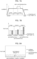
- FIG. 7A and FIG. 7B the state of region division and the state of deterioration determination based on the feature in the present embodiment is schematically illustrated.
- the zone of one process (unit process) relating to injection from the start point to the end point is divided into an optional plurality of regions.
- the place at which the nut part 18 is located on the screw shaft 17 can be sensed based on the number of rotations of the motor 13.
- the zone of one process is divided into three zones 1 to 3 of every 10 rotations.
- the dividing method is not limited to even dividing and may be uneven dividing.
- the zone of one process may be divided in such a manner that the zone in which the relevant deterioration is anticipated is set larger (or smaller) than the other zones.
- the feature calculating section 121 and the computing section 122 measure current values equal to or smaller than a threshold (normal values) in current values sensed at predetermined time intervals in each zone and the number of current values equal to or smaller than the threshold, and calculate the average thereof. Similarly, the feature calculating section 121 and the computing section 122 measure current values larger than the threshold (abnormal values) in the current values sensed at the predetermined time intervals in each zone and the number of current values larger than the threshold, and calculates the average thereof. Thereafter, the feature calculating section 121 and the computing section 122 output these results to the state estimating section 42.
- FIG. 7B the feature (average value) of the current of each zone is schematically illustrated.
- the average value of the abnormal value is larger than the average value of the normal value and is the largest in comparison with the other zones.
- the state estimating section 42 determines that the screw shaft 17 has deteriorated, and outputs the deterioration and the deterioration position to the motor control updating section 46 and the information transmitting section 45.
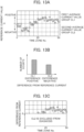
- FIG. 8A and 8B one example of comparison of results between the case in which the deterioration determination based on such a feature is executed and the case in which the deterioration determination is not executed is schematically illustrated.
- FIG. 8A is an example of the case in which merely comparison of the current value is executed without executing the above-described deterioration determination processing. That is, FIG. 8A is obtained by calculating, as the feature, the difference value between the average value of the current in normal times (in the present verification, the average value of the current of 50 processes of normal data) and the average value of the current of each sample, and indicating the calculation result regarding each cycle. As illustrated in this diagram, there is the case in which a difference value (difference amount) D of the average value between the normal value and the abnormal value is slight.
- the difference value (difference amount) D between a normal current value group and an abnormal current value group increases compared with the case illustrated in FIG. 8A , and the difference between the normal products and the deteriorated products enlarges (that is, the sensitivity of sensing of deterioration increases). That is, in the above-described deterioration determination, one process is first divided into a plurality of regions and the average between the normal value and the abnormal value in each of these divided sections is calculated.
- the number of samples in the calculation of the average value is small, and the degree at which a prominently large value affects the average value becomes higher than that in the case of calculating the average value without executing the deterioration determination processing (system of FIG. 8A ).
- the abnormal average value of the zone in which the average value of the abnormal value is higher among the respective divided regions susceptible to the influence of the prominently large value as above is treated as the abnormal value in the relevant one cycle (process). Therefore, the difference between the most abnormal average value of the current value and the normal average value appears as a relatively large current value difference.
- one process is divided into a plurality of zones, the average values of the normal value and the abnormal value of each zone are calculated, and the value of the highest abnormal value average among them is deemed as the target of deterioration determination.
- deterioration detection on the power transmission mechanism can be sensed with higher precision and probability.
- an effect of improvement in the precision and the probability with which sensing as an abnormality is allowed even when deterioration of the power transmission mechanism is small or even when deterioration is at the initial stage can be expected.
- the abnormal value often varies compared with the normal value depending on deterioration of the power transmission mechanism, and it is thought that it is also possible to execute deterioration determination by determining also this variation.
- abnormality detection on the power transmission mechanism can be sensed with higher precision and probability.
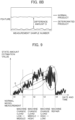
- FIG. 9 is a diagram that explains state amount fluctuation of the power transmission mechanism, that is, variation in the abnormal value.
- the ordinate axis indicates the state amount estimation value and the abscissa axis indicates the elapsed date and time.
- a normal model is measured, and the state amount of the power transmission mechanism in the normal state is set.
- the load is changed from a low load to a middle load at date and time t1, and the load is changed from the middle load to a high load at date and time t2.
- the load is changed from the high load to the low load at date and time t3, and the machine is repaired at date and time t4.
- a state amount E increases while fluctuating from the date and time t0 toward the date and time t3.
- the state amount E makes the transition with normal fluctuation width (variation).
- the fluctuation width (variation) of the state amount E is larger than the fluctuation width (variation) of the period from the date and time t0 to t3 and it can be determined that an abnormality has occurred.
- FIG. 10 is a diagram that explains sensing of a peak value and a peak value of features.
- the features are derived in a diagnosis zone, the peak value (positive side) and the peak value (negative side) of the features are sensed, and the state amount estimation value (pk-pk value) is calculated.
- the ordinate axis of a graph of FIG. 10 indicates the feature and the abscissa axis indicates the time zone number.
- a plurality of circle marks in the graph indicate the features of the respective time zones.
- the features larger than the feature of a normal model are indicated in the region in which the difference is positive in the upper half of the graph, and the features smaller than the feature of the normal model are indicated in the region in which the difference is negative in the lower half of the graph.
- the difference (absolute value) between pk1 (maximum average current value) that is the feature of the maximum value in the region in which the difference is positive and pk2 (minimum average current value) that is the feature of the minimum value in the region in which the difference is negative is deemed as the state amount estimation value, and whether or not an abnormality has occurred can be determined from this state amount estimation value.
- the "reference current value serving as the basis" used for the feature calculation may be generated by the state estimating section 42 or may be prepared as a profile by the user in advance. Furthermore, it is also possible that the user obtains an average current value and sets it as the reference value in advance.
- FIG. 11 is a flowchart of computation of the difference between the peak value (positive side) and the peak value (negative side) of the features executed in the computing section 122.
- step S1 in FIG. 11 whether or not a calculated feature is larger than the maximum feature is determined.
- the processing proceeds to a step S2 and the calculated feature is defined as the maximum feature, and the processing proceeds to a step S3.
- the processing proceeds to the step S3.
- step S3 whether or not the calculated feature is smaller than the minimum feature is determined.
- the processing proceeds to a step S4 and the calculated feature is defined as the minimum feature, and the processing proceeds to a step S5.
- the processing proceeds to the step S5.
- step S5 the minimum feature is subtracted from the maximum feature to make the state amount estimation value.
- Determination of abnormality occurrence can be executed through comparing the obtained state amount estimation value with a normal state amount estimation value defined in advance.
- the determination of abnormality occurrence is executed in the computing section 122 and the result thereof can be displayed on the information transmitting section 45.
- measured data may be all displayed, or it is also possible to display data at an interval of a specified number of days instead of displaying all of the data. For example, even when data is measured every day, regarding display, data of every one week is displayed.
- the management method of the present invention is a management method for a power transmission mechanism that transmits a driving force from an electric motor to a load-side device, and includes a current acquisition step of acquiring the current value per unit process in which the power transmission mechanism is driven, an average current value calculation step of dividing the unit process into multiple zones and calculating the average current value obtained by averaging the current value of each zone, and an abnormality detection step of executing abnormality detection.
- the abnormality detection step calculates the state amount estimation value on the basis of the average current value of the multiple zones and executes abnormality sensing in the unit process on the basis of the state amount estimation value.
- one process is divided into multiple zones, the difference between the average value of the current value of each zone and the normal value is calculated, and the maximum value among them is defined as the feature. Furthermore, the variation (pk-pk value) in the feature in multiple processes (multiple time zones) is calculated as the state amount estimation value, and an abnormality of the power transmission mechanism is determined based on the calculated state amount estimation value.
- embodiment example 2 of the present invention is similar to that of embodiment example 1, and therefore illustration and detailed description are omitted.
- the average value of the features in the region in which the current value difference from a reference current value Io indicated at the center of the ordinate axis of the graph of FIG. 10 is positive is defined as a first current value group average value (FVave1)
- the average value of the features in the region in which the current value difference from the reference current value Io is negative is defined as a second current value group average value (FVave2).
- the absolute value of the difference between the first current value group average value and the second current value group average value is calculated as the state amount estimation value (abs(FVave1 - FVave2)).
- determination of an abnormality is executed by using the state amount estimation value (abs(FVave1 - FVave2)) .
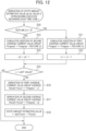
- FIG. 12 is a flowchart of computation of the state amount estimation value executed in the computing section 122.
- step S10 in FIG. 12 whether or not the feature is equal to or larger than 0 is determined.
- the processing proceeds to a step S11.
- step S11 cumulative addition of the first average current value group is executed (FVsigma1 ⁇ FVsigma1 + feature). Then, the processing proceeds to a step S12, n1 + 1 is employed as n1, and the processing proceeds to a step S15.
- step S13 cumulative addition of the second average current value group is executed (FVsigma2 ⁇ FVsigma2 + feature). Then, the processing proceeds to a step S14, n2 + 1 is employed as n2, and the processing proceeds to the step S15.
- step S15 whether or not n is the last value is determined. When n is not the last value, the processing ends.
- n is the last value in the step S15
- the processing proceeds to a step S16 and derivation (calculation) of the first average current value group average value is executed (FVave1 ⁇ FVsigma1/n1).
- the processing proceeds to a step S17 and derivation (calculation) of the second average current value group average value is executed (FVave2 ⁇ FVsigma2/n2).
- the processing proceeds to a step S18, the state amount estimation value is set to abs(FVave1 - FVave2), and the processing is ended.
- embodiment example 3 of the present invention is similar to that of embodiment example 1, and therefore illustration and detailed description are omitted.
- a first average current group CL1 of the features average value of the region in which the difference from the reference current value Io is positive is acquired and the average value of the features in the region in which the difference from the reference current value Io is negative is defined as a second average current value group CL2.
- the number of features of the first average current value group CL1 and the number of features of the second average current value group CL2 are compared with each other (illustrated in FIG. 13B ).
- the number of features of the first average current value group CL1 is larger than the number of features of the second average current value group CL2. In this case, as illustrated in FIG.
- the features of the second average current value group CL2 are excluded from the diagnosis of an abnormality, and the diagnosis of an abnormality is executed by using the features of the first average current value group CL1. That is, it is an example in which, based on the rule of majority, the diagnosis of an abnormality is executed by using the data of the region with a larger number of pieces of data. This example can be applied to abnormality diagnosis of the power transmission mechanism in which load fluctuation is frequently large or the power transmission mechanism in a transient state.
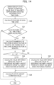
- FIG. 14 is a flowchart of computation of the state amount estimation value executed in the computing section 122.
- the feature of each time zone is calculated in a step S20 and the processing proceeds to a step S21.
- the step S21 whether or not the features of all time zones have been calculated is determined. The processing ends when the features have not been calculated, and the processing proceeds to a step S22 when the features have been calculated.
- step S22 the number N1 of features in the time zones in which the feature is positive and the number N2 of features in the time zones in which the feature is negative are calculated. Then, in a step S23, whether or not the number N1 is larger than the number N2 is determined. When the number N1 is larger than the number N2, the processing proceeds to a step S24, the value with which the absolute value of the difference becomes the maximum is calculated from the data group CL1 about which the feature is positive, and the processing proceeds to a step S26.
- step S23 When the number N1 is not larger than the number N2 in the step S23, the processing proceeds to a step S25, the value with which the absolute value of the difference becomes the maximum is calculated from the data group CL2 about which the feature is negative, and the processing proceeds to the step S26.
- step S26 the state amount estimation value is calculated, and the processing is ended.
- embodiment example 4 of the present invention is similar to that of embodiment example 1, and therefore illustration and detailed description are omitted.
- the features that exceed a positive threshold (vmax) in the region in which the difference is positive and the features smaller than a negative threshold (vmin) in the region in which the difference is negative are excluded as outliers, and the state amount estimation value is calculated by using the features that are equal to or smaller than the positive threshold and equal to or larger than the negative threshold.
- a method similar to that of embodiment example 1, embodiment example 2, or embodiment example 3 can be used.
- FIG. 16 is a flowchart of computation of the state amount estimation value through exclusion of features as outliers, executed in the computing section 122.
- a calculated feature is equal to or smaller than the positive threshold (vmax) and equal to or larger than the negative threshold (vmin).
- the processing proceeds to a step S31. The processing ends when the calculated feature is not equal to or smaller than the positive threshold (vmax) or equal to or larger than the negative threshold (vmin) in the step S30.
- step S31 whether or not the calculated feature is larger than feature max is determined.
- the processing proceeds to a step S32, the calculated feature is defined as the maximum feature (feature max), and the processing proceeds to a step S33.
- the processing proceeds to the step S33.
- step S33 whether or not the calculated feature is smaller than feature min is determined.
- the processing proceeds to a step S34, the calculated feature is defined as the minimum feature (feature min), and the processing proceeds to a step S35.
- the processing proceeds to the step S35.
- step S35 feature min is subtracted from feature max to make the state amount estimation value.
- embodiment example 5 of the present invention is similar to that of embodiment example 1, and therefore illustration and detailed description are omitted.
- Embodiment example 5 is an example in which an abnormality such as mixing with foreign matter occurs in the power transmission mechanism and the occurrence of the abnormality and the abnormality place can be sensed.
- Embodiment example 5 is an example that can be applied in addition to the abnormality sensing in embodiment examples 1 to 4.
- FIG. 17 is a diagram that explains a method for sensing (extracting) an abnormality occurrence position X in the case in which an abnormality has occurred, such as the case in which foreign matter is mixed into the power transmission mechanism.
- FIG. 18 is a schematic diagram illustrating the functional configuration of the feature calculating section and the computing section in embodiment example 5, and a position acquiring section 123 is added to the example illustrated in FIG. 5 .
- the position acquiring section 123 acquires position information per unit process in which the power transmission mechanism is driven.
- the position acquiring section 123 acquires the position information of the power transmission mechanism at substantially the same timing as the current acquiring section that is the control internal value creating section 43.
- the position acquiring section 123 outputs the position corresponding to the unit process when an abnormality of the power transmission mechanism is sensed.
- the current value changes in a pulsed manner as illustrated by a dashed line.
- the feature similarly to the current waveform in abnormal times, the feature also suddenly rises and thereafter falls down in a short time, as illustrated by a dashed line, when the abnormality such as mixing with foreign matter has occurred.
- the amount of rise of the feature is a state amount estimation value.
- the position at which the abnormality such as mixing with foreign matter has occurred corresponds to the timing when the feature has risen up and fallen down between the time position of the rotation start of the motor 13 and the end time.
- a position X of the motor 13 at this time can be extracted and a position corresponding to it, for example, the position of the screw shaft 17, can be extracted.
- the rotational position of the motor 13 is input to the position acquiring section 123.
- the feature is output from the computing section 122 to the position acquiring section 123, and the position acquiring section 123 acquires an abnormality position such as a position of mixing with foreign matter on the screw shaft 17 from the rotational position of the motor 13 corresponding to the timing when the feature has risen up or fallen down, and transmits the information on the abnormality position to the computing section 122.
- the computing section 122 outputs the abnormality occurrence position on the screw shaft 17 to the information transmitting section 45 together with a state amount estimation value Y.
- the information transmitting section 45 informs the user of the occurrence of an abnormality and the abnormality occurrence position on the screw shaft 17 by display or the like.
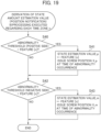
- FIG. 19 is a flowchart that explains a method for executing sensing of the abnormality occurrence position.
- a step S40 in FIG. 19 whether or not the feature is larger than an abnormality threshold (positive side) is determined.
- the feature is larger than the abnormality threshold (positive side)
- the feature is employed as a state amount estimation value p and a position Xp of the screw shaft 17 at the time of abnormality occurrence is issued.
- the processing proceeds to a step S42.
- the processing proceeds to the step S42.
- step S42 whether or not the feature is smaller than an abnormality threshold (negative side) is determined.
- the feature is employed as a state amount estimation value m and a position Xm of the screw shaft 17 at the time of abnormality occurrence is issued. Then, the processing is ended. Furthermore, the processing is ended also when the feature is not smaller than the abnormality threshold (negative side) in the step S42.
- each of the graphs illustrated in FIG. 9 , FIG. 10 , and FIG. 15 can be displayed on the information transmitting section 45.
- the present invention can implement a management system including the above-described management device 30 and the power transmission mechanism.
- the power transmission mechanism in the management system can include the drive pulley 14, the driven pulley 15, the timing belt 16, the ball screw mechanism 20, and the nut part 18.
- the power transmission mechanism applied to the management system of the present invention is not limited to the above-described example and can be applied also to a power transmission mechanism such as a gear mechanism, for example.
- the present invention is not limited to the above-described various configurations and functions, and various kinds of changes and replacement can be made in such a range as not to depart from the gist thereof.
- the injection molding machine 1 is employed as an application example in the above-described embodiment.
- the present invention can be applied to what transmits power of a motor that is a drive source of a load-side device to load-side equipment through a power transmission mechanism, such as press apparatus and cutting apparatus, as already described.
- the deterioration determination based on the feature is executed regarding the screw shaft 17 of the ball screw mechanism 20 as the power transmission mechanism.
- the present invention it is also possible to apply the present invention to the deterioration determination of the timing belt 16 or a chain or the like instead of it as the power transmission mechanism.
- the ball screw mechanism 20 is applied as the power transmission mechanism.
- the present invention can be applied also to a screw mechanism composed of a screw bolt and a nut without the interposition of balls.
Landscapes
- Physics & Mathematics (AREA)
- General Physics & Mathematics (AREA)
- Engineering & Computer Science (AREA)
- Automation & Control Theory (AREA)
- Manufacturing & Machinery (AREA)
- Mechanical Engineering (AREA)
- Injection Moulding Of Plastics Or The Like (AREA)
- Cash Registers Or Receiving Machines (AREA)
- Remote Monitoring And Control Of Power-Distribution Networks (AREA)
Applications Claiming Priority (2)
| Application Number | Priority Date | Filing Date | Title |
|---|---|---|---|
| JP2021210040 | 2021-12-24 | ||
| PCT/JP2022/021182 WO2023119686A1 (ja) | 2021-12-24 | 2022-05-24 | 動力伝達機構の管理装置、動力伝達機構の管理方法及び管理システム |
Publications (2)
| Publication Number | Publication Date |
|---|---|
| EP4455818A1 true EP4455818A1 (de) | 2024-10-30 |
| EP4455818A4 EP4455818A4 (de) | 2025-12-17 |
Family
ID=86901790
Family Applications (1)
| Application Number | Title | Priority Date | Filing Date |
|---|---|---|---|
| EP22910417.9A Pending EP4455818A4 (de) | 2021-12-24 | 2022-05-24 | Verwaltungsvorrichtung für einen leistungsübertragungsmechanismus, verwaltungsverfahren für einen leistungsübertragungsmechanismus und verwaltungssystem |
Country Status (6)
| Country | Link |
|---|---|
| US (1) | US20240385082A1 (de) |
| EP (1) | EP4455818A4 (de) |
| JP (1) | JP7716504B2 (de) |
| CN (1) | CN118475820A (de) |
| TW (1) | TWI839828B (de) |
| WO (1) | WO2023119686A1 (de) |
Family Cites Families (22)
| Publication number | Priority date | Publication date | Assignee | Title |
|---|---|---|---|---|
| JP3461937B2 (ja) * | 1994-11-18 | 2003-10-27 | 東亜ディーケーケー株式会社 | 絶縁抵抗の測定方法 |
| JP3688890B2 (ja) * | 1998-05-12 | 2005-08-31 | 新日本製鐵株式会社 | ローラーテーブルの設備診断方法及び設備診断装置 |
| JP4138267B2 (ja) * | 2001-03-23 | 2008-08-27 | 株式会社東芝 | 半導体製造装置、真空ポンプの寿命予測方法及び真空ポンプの修理タイミング決定方法 |
| JP3967245B2 (ja) * | 2002-09-30 | 2007-08-29 | 株式会社東芝 | 回転機の寿命予測方法及び回転機を有する製造装置 |
| US8075499B2 (en) * | 2007-05-18 | 2011-12-13 | Vaidhi Nathan | Abnormal motion detector and monitor |
| JP2009045510A (ja) * | 2007-08-13 | 2009-03-05 | Toshiba Corp | 水処理プラントの運転支援システム及び方法 |
| JP2013045325A (ja) * | 2011-08-25 | 2013-03-04 | Hitachi Ltd | 制御システムの制御装置及びエレベータシステム |
| JP6540568B2 (ja) * | 2016-03-23 | 2019-07-10 | 株式会社デンソー | 電子制御装置 |
| JP6348161B2 (ja) * | 2016-11-29 | 2018-06-27 | ファナック株式会社 | 射出成形機の制御装置及び管理システム |
| EP3336634B1 (de) * | 2016-12-14 | 2020-02-26 | ABB Schweiz AG | Computersystem und verfahren zur überwachung des status eines technischen systems |
| CN110088589B (zh) | 2016-12-15 | 2020-12-11 | 三菱电机株式会社 | 动力传递机构的异常诊断装置以及动力传递机构的异常诊断方法 |
| CN106771929A (zh) * | 2017-01-13 | 2017-05-31 | 国家电网公司 | 一种gis设备取消例行停电试验的状态试验方法 |
| WO2018158910A1 (ja) * | 2017-03-02 | 2018-09-07 | 株式会社日立製作所 | 診断装置および診断方法 |
| JP6899897B2 (ja) * | 2017-05-31 | 2021-07-07 | 株式会社日立製作所 | 状態監視装置、並びに機器システム |
| JP7403213B2 (ja) * | 2017-10-31 | 2023-12-22 | 株式会社荏原製作所 | 研磨装置、及び研磨方法 |
| JP6947654B2 (ja) * | 2018-01-19 | 2021-10-13 | 住友重機械工業株式会社 | プレス装置及びプレス装置の診断方法 |
| JP7194069B2 (ja) * | 2019-04-18 | 2022-12-21 | 株式会社日立産機システム | 監視装置、および監視方法 |
| JP7371512B2 (ja) * | 2019-09-10 | 2023-10-31 | オムロン株式会社 | 診断装置、方法、及びプログラム |
| JP7275008B2 (ja) * | 2019-11-14 | 2023-05-17 | 株式会社日立製作所 | 診断装置、モータ駆動装置および診断方法 |
| JP2021136779A (ja) * | 2020-02-27 | 2021-09-13 | Ntn株式会社 | 電動アクチュエータ |
| US11604456B2 (en) * | 2020-03-11 | 2023-03-14 | Ford Global Technologies, Llc | System for monitoring machining processes of a computer numerical control machine |
| CN115606062B (zh) * | 2020-05-21 | 2025-07-25 | 三菱电机株式会社 | 电动机控制装置及电动助力转向装置 |
-
2022
- 2022-05-24 EP EP22910417.9A patent/EP4455818A4/de active Pending
- 2022-05-24 CN CN202280066394.3A patent/CN118475820A/zh active Pending
- 2022-05-24 WO PCT/JP2022/021182 patent/WO2023119686A1/ja not_active Ceased
- 2022-05-24 US US18/696,100 patent/US20240385082A1/en active Pending
- 2022-05-24 JP JP2023569039A patent/JP7716504B2/ja active Active
- 2022-09-01 TW TW111133098A patent/TWI839828B/zh active
Also Published As
| Publication number | Publication date |
|---|---|
| CN118475820A (zh) | 2024-08-09 |
| EP4455818A4 (de) | 2025-12-17 |
| JP7716504B2 (ja) | 2025-07-31 |
| US20240385082A1 (en) | 2024-11-21 |
| TWI839828B (zh) | 2024-04-21 |
| WO2023119686A9 (ja) | 2024-07-11 |
| JPWO2023119686A1 (de) | 2023-06-29 |
| WO2023119686A1 (ja) | 2023-06-29 |
| TW202326327A (zh) | 2023-07-01 |
Similar Documents
| Publication | Publication Date | Title |
|---|---|---|
| JP7315797B2 (ja) | 動力伝達機構の管理装置、動力伝達機構の管理方法 | |
| JP6787971B2 (ja) | 状態判定装置及び状態判定方法 | |
| US11150636B2 (en) | State determination device and state determination method | |
| JP6899897B2 (ja) | 状態監視装置、並びに機器システム | |
| JP6867358B2 (ja) | 状態判定装置及び状態判定方法 | |
| JP7010861B2 (ja) | 状態判定装置及び状態判定方法 | |
| US10216151B2 (en) | Power consumption-amount estimation apparatus | |
| US11772312B2 (en) | State determination device and state determination method for determining operation state of injection molding machine | |
| EP4455818A1 (de) | Verwaltungsvorrichtung für einen leistungsübertragungsmechanismus, verwaltungsverfahren für einen leistungsübertragungsmechanismus und verwaltungssystem | |
| JP6184772B2 (ja) | 転換異常判定解析装置及びプログラム | |
| JP2021066057A (ja) | 射出成形機管理装置及び射出成形機 | |
| EP3691113B1 (de) | Vorrichtungssteuerungssystem | |
| WO2022085580A9 (ja) | 成形条件設定装置及び成形条件設定方法 | |
| CN108693841B (zh) | 制造系统以及制造方法 | |
| JP2011208956A (ja) | 電動機のトルク推定システム及びその推定方法 | |
| JP7184997B2 (ja) | 状態判定装置及び状態判定方法 | |
| US20230405902A1 (en) | State determination device and state determination method | |
| WO2023053453A1 (ja) | 制御装置及び制御方法 | |
| JP7614345B2 (ja) | モータの制御装置、産業機械システム、及びモータの制御方法 | |
| US20240278469A1 (en) | A method for controlling an injection molding machine | |
| JP2013203044A (ja) | 周波数特性の管理機能を有する射出成形機の管理装置 | |
| WO2018193649A1 (ja) | 電動機制御装置 | |
| WO2024224469A1 (ja) | 決定装置および決定方法 | |
| WO2024224468A1 (ja) | 判定装置および判定方法 | |
| WO2024224470A1 (ja) | 判定装置および判定方法 |
Legal Events
| Date | Code | Title | Description |
|---|---|---|---|
| STAA | Information on the status of an ep patent application or granted ep patent |
Free format text: STATUS: THE INTERNATIONAL PUBLICATION HAS BEEN MADE |
|
| PUAI | Public reference made under article 153(3) epc to a published international application that has entered the european phase |
Free format text: ORIGINAL CODE: 0009012 |
|
| STAA | Information on the status of an ep patent application or granted ep patent |
Free format text: STATUS: REQUEST FOR EXAMINATION WAS MADE |
|
| 17P | Request for examination filed |
Effective date: 20240328 |
|
| AK | Designated contracting states |
Kind code of ref document: A1 Designated state(s): AL AT BE BG CH CY CZ DE DK EE ES FI FR GB GR HR HU IE IS IT LI LT LU LV MC MK MT NL NO PL PT RO RS SE SI SK SM TR |
|
| DAV | Request for validation of the european patent (deleted) | ||
| DAX | Request for extension of the european patent (deleted) | ||
| A4 | Supplementary search report drawn up and despatched |
Effective date: 20251113 |
|
| RIC1 | Information provided on ipc code assigned before grant |
Ipc: G05B 23/02 20060101AFI20251107BHEP Ipc: G01M 13/02 20190101ALI20251107BHEP Ipc: G01R 19/00 20060101ALI20251107BHEP Ipc: G01R 19/165 20060101ALI20251107BHEP |