EP4455433A1 - Garagenschwenktor mit im festen rahmen integrierter motorisierung - Google Patents
Garagenschwenktor mit im festen rahmen integrierter motorisierung Download PDFInfo
- Publication number
- EP4455433A1 EP4455433A1 EP24157179.3A EP24157179A EP4455433A1 EP 4455433 A1 EP4455433 A1 EP 4455433A1 EP 24157179 A EP24157179 A EP 24157179A EP 4455433 A1 EP4455433 A1 EP 4455433A1
- Authority
- EP
- European Patent Office
- Prior art keywords
- garage door
- support
- motor
- fixed frame
- upright
- Prior art date
- Legal status (The legal status is an assumption and is not a legal conclusion. Google has not performed a legal analysis and makes no representation as to the accuracy of the status listed.)
- Granted
Links
Images


Classifications
-
- E—FIXED CONSTRUCTIONS
- E05—LOCKS; KEYS; WINDOW OR DOOR FITTINGS; SAFES
- E05D—HINGES OR SUSPENSION DEVICES FOR DOORS, WINDOWS OR WINGS
- E05D13/00—Accessories for sliding or lifting wings, e.g. pulleys, safety catches
- E05D13/10—Counterbalance devices
- E05D13/12—Counterbalance devices with springs
- E05D13/1207—Counterbalance devices with springs with tension springs
- E05D13/1215—Counterbalance devices with springs with tension springs specially adapted for overhead wings
-
- E—FIXED CONSTRUCTIONS
- E05—LOCKS; KEYS; WINDOW OR DOOR FITTINGS; SAFES
- E05D—HINGES OR SUSPENSION DEVICES FOR DOORS, WINDOWS OR WINGS
- E05D15/00—Suspension arrangements for wings
- E05D15/40—Suspension arrangements for wings supported on arms movable in vertical planes
- E05D15/406—Suspension arrangements for wings supported on arms movable in vertical planes with pivoted arms and sliding guides
- E05D15/408—Suspension arrangements for wings supported on arms movable in vertical planes with pivoted arms and sliding guides with sliding guides fixed to the wing
-
- E—FIXED CONSTRUCTIONS
- E05—LOCKS; KEYS; WINDOW OR DOOR FITTINGS; SAFES
- E05F—DEVICES FOR MOVING WINGS INTO OPEN OR CLOSED POSITION; CHECKS FOR WINGS; WING FITTINGS NOT OTHERWISE PROVIDED FOR, CONCERNED WITH THE FUNCTIONING OF THE WING
- E05F15/00—Power-operated mechanisms for wings
- E05F15/60—Power-operated mechanisms for wings using electrical actuators
- E05F15/603—Power-operated mechanisms for wings using electrical actuators using rotary electromotors
- E05F15/665—Power-operated mechanisms for wings using electrical actuators using rotary electromotors for vertically-sliding wings
- E05F15/668—Power-operated mechanisms for wings using electrical actuators using rotary electromotors for vertically-sliding wings for overhead wings
- E05F15/678—Power-operated mechanisms for wings using electrical actuators using rotary electromotors for vertically-sliding wings for overhead wings operated by swinging lever arms
-
- E—FIXED CONSTRUCTIONS
- E05—LOCKS; KEYS; WINDOW OR DOOR FITTINGS; SAFES
- E05Y—INDEXING SCHEME ASSOCIATED WITH SUBCLASSES E05D AND E05F, RELATING TO CONSTRUCTION ELEMENTS, ELECTRIC CONTROL, POWER SUPPLY, POWER SIGNAL OR TRANSMISSION, USER INTERFACES, MOUNTING OR COUPLING, DETAILS, ACCESSORIES, AUXILIARY OPERATIONS NOT OTHERWISE PROVIDED FOR, APPLICATION THEREOF
- E05Y2201/00—Constructional elements; Accessories therefor
- E05Y2201/10—Covers; Housings
-
- E—FIXED CONSTRUCTIONS
- E05—LOCKS; KEYS; WINDOW OR DOOR FITTINGS; SAFES
- E05Y—INDEXING SCHEME ASSOCIATED WITH SUBCLASSES E05D AND E05F, RELATING TO CONSTRUCTION ELEMENTS, ELECTRIC CONTROL, POWER SUPPLY, POWER SIGNAL OR TRANSMISSION, USER INTERFACES, MOUNTING OR COUPLING, DETAILS, ACCESSORIES, AUXILIARY OPERATIONS NOT OTHERWISE PROVIDED FOR, APPLICATION THEREOF
- E05Y2201/00—Constructional elements; Accessories therefor
- E05Y2201/20—Brakes; Disengaging means; Holders; Stops; Valves; Accessories therefor
- E05Y2201/224—Stops
-
- E—FIXED CONSTRUCTIONS
- E05—LOCKS; KEYS; WINDOW OR DOOR FITTINGS; SAFES
- E05Y—INDEXING SCHEME ASSOCIATED WITH SUBCLASSES E05D AND E05F, RELATING TO CONSTRUCTION ELEMENTS, ELECTRIC CONTROL, POWER SUPPLY, POWER SIGNAL OR TRANSMISSION, USER INTERFACES, MOUNTING OR COUPLING, DETAILS, ACCESSORIES, AUXILIARY OPERATIONS NOT OTHERWISE PROVIDED FOR, APPLICATION THEREOF
- E05Y2201/00—Constructional elements; Accessories therefor
- E05Y2201/40—Motors; Magnets; Springs; Weights; Accessories therefor
- E05Y2201/47—Springs
- E05Y2201/488—Traction springs
-
- E—FIXED CONSTRUCTIONS
- E05—LOCKS; KEYS; WINDOW OR DOOR FITTINGS; SAFES
- E05Y—INDEXING SCHEME ASSOCIATED WITH SUBCLASSES E05D AND E05F, RELATING TO CONSTRUCTION ELEMENTS, ELECTRIC CONTROL, POWER SUPPLY, POWER SIGNAL OR TRANSMISSION, USER INTERFACES, MOUNTING OR COUPLING, DETAILS, ACCESSORIES, AUXILIARY OPERATIONS NOT OTHERWISE PROVIDED FOR, APPLICATION THEREOF
- E05Y2600/00—Mounting or coupling arrangements for elements provided for in this subclass
- E05Y2600/10—Adjustable
- E05Y2600/14—Adjustable with position retaining means
-
- E—FIXED CONSTRUCTIONS
- E05—LOCKS; KEYS; WINDOW OR DOOR FITTINGS; SAFES
- E05Y—INDEXING SCHEME ASSOCIATED WITH SUBCLASSES E05D AND E05F, RELATING TO CONSTRUCTION ELEMENTS, ELECTRIC CONTROL, POWER SUPPLY, POWER SIGNAL OR TRANSMISSION, USER INTERFACES, MOUNTING OR COUPLING, DETAILS, ACCESSORIES, AUXILIARY OPERATIONS NOT OTHERWISE PROVIDED FOR, APPLICATION THEREOF
- E05Y2600/00—Mounting or coupling arrangements for elements provided for in this subclass
- E05Y2600/40—Mounting location; Visibility of the elements
- E05Y2600/45—Mounting location; Visibility of the elements in or on the fixed frame
-
- E—FIXED CONSTRUCTIONS
- E05—LOCKS; KEYS; WINDOW OR DOOR FITTINGS; SAFES
- E05Y—INDEXING SCHEME ASSOCIATED WITH SUBCLASSES E05D AND E05F, RELATING TO CONSTRUCTION ELEMENTS, ELECTRIC CONTROL, POWER SUPPLY, POWER SIGNAL OR TRANSMISSION, USER INTERFACES, MOUNTING OR COUPLING, DETAILS, ACCESSORIES, AUXILIARY OPERATIONS NOT OTHERWISE PROVIDED FOR, APPLICATION THEREOF
- E05Y2600/00—Mounting or coupling arrangements for elements provided for in this subclass
- E05Y2600/60—Mounting or coupling members; Accessories therefor
- E05Y2600/626—Plates or brackets
-
- E—FIXED CONSTRUCTIONS
- E05—LOCKS; KEYS; WINDOW OR DOOR FITTINGS; SAFES
- E05Y—INDEXING SCHEME ASSOCIATED WITH SUBCLASSES E05D AND E05F, RELATING TO CONSTRUCTION ELEMENTS, ELECTRIC CONTROL, POWER SUPPLY, POWER SIGNAL OR TRANSMISSION, USER INTERFACES, MOUNTING OR COUPLING, DETAILS, ACCESSORIES, AUXILIARY OPERATIONS NOT OTHERWISE PROVIDED FOR, APPLICATION THEREOF
- E05Y2600/00—Mounting or coupling arrangements for elements provided for in this subclass
- E05Y2600/60—Mounting or coupling members; Accessories therefor
- E05Y2600/628—Profiles; Strips
-
- E—FIXED CONSTRUCTIONS
- E05—LOCKS; KEYS; WINDOW OR DOOR FITTINGS; SAFES
- E05Y—INDEXING SCHEME ASSOCIATED WITH SUBCLASSES E05D AND E05F, RELATING TO CONSTRUCTION ELEMENTS, ELECTRIC CONTROL, POWER SUPPLY, POWER SIGNAL OR TRANSMISSION, USER INTERFACES, MOUNTING OR COUPLING, DETAILS, ACCESSORIES, AUXILIARY OPERATIONS NOT OTHERWISE PROVIDED FOR, APPLICATION THEREOF
- E05Y2800/00—Details, accessories and auxiliary operations not otherwise provided for
- E05Y2800/20—Combinations of elements
- E05Y2800/21—Combinations of elements of identical elements, e.g. of identical compression springs
-
- E—FIXED CONSTRUCTIONS
- E05—LOCKS; KEYS; WINDOW OR DOOR FITTINGS; SAFES
- E05Y—INDEXING SCHEME ASSOCIATED WITH SUBCLASSES E05D AND E05F, RELATING TO CONSTRUCTION ELEMENTS, ELECTRIC CONTROL, POWER SUPPLY, POWER SIGNAL OR TRANSMISSION, USER INTERFACES, MOUNTING OR COUPLING, DETAILS, ACCESSORIES, AUXILIARY OPERATIONS NOT OTHERWISE PROVIDED FOR, APPLICATION THEREOF
- E05Y2800/00—Details, accessories and auxiliary operations not otherwise provided for
- E05Y2800/26—Form or shape
- E05Y2800/27—Profiles; Strips
- E05Y2800/272—Profiles; Strips hollow
- E05Y2800/276—U-shaped
-
- E—FIXED CONSTRUCTIONS
- E05—LOCKS; KEYS; WINDOW OR DOOR FITTINGS; SAFES
- E05Y—INDEXING SCHEME ASSOCIATED WITH SUBCLASSES E05D AND E05F, RELATING TO CONSTRUCTION ELEMENTS, ELECTRIC CONTROL, POWER SUPPLY, POWER SIGNAL OR TRANSMISSION, USER INTERFACES, MOUNTING OR COUPLING, DETAILS, ACCESSORIES, AUXILIARY OPERATIONS NOT OTHERWISE PROVIDED FOR, APPLICATION THEREOF
- E05Y2900/00—Application of doors, windows, wings or fittings thereof
- E05Y2900/10—Application of doors, windows, wings or fittings thereof for buildings or parts thereof
- E05Y2900/106—Application of doors, windows, wings or fittings thereof for buildings or parts thereof for garages
Definitions
- the present invention relates to a tilting garage door for closing a garage opening or any other room, comprising a fixed frame provided with two side uprights, a closing panel coupled to each of said side uprights by a main lever and a rotation shaft, a motorization mounted in the side uprights of said fixed frame and coupled to each of said rotation shafts to move said closing panel between a closed position and an open position, and vice versa, and a compensation mechanism provided in said side uprights and coupled to each of said main levers.
- This type of tilting garage door of the circular movement type, is well known and used to close the entrance to a garage or any other room.
- the publication FR 2 871 189 B1 of the applicant proposes a motorization solution integrated into the fixed frame of the garage door, which makes it possible to do without the guide rails on the ceiling and offers many advantages.
- the installation of the garage door does not require any masonry work or electricity, a simple electrical connection to a mains socket is sufficient.
- the garage door is silent, because the shutter panel has great lateral stability and moves uniformly without jolting or jerking.
- the motorization is mounted in the side uprights of the fixed frame by means of various support parts suitable for receiving the engine block, the bearings of the shutter panel rotation axes, the attachment points of the compensation springs, etc.
- These support parts are welded individually and directly onto the side uprights at specific locations.
- the support parts and the specific locations vary depending on the dimensions of the shutter panel, the height position of the rotation shaft, and the type of garage door assembly.
- This manufacturing method involves production and inventory management of different support parts, which is restrictive and costly.
- welding operations require prior tracing, precision of execution and significant factory intervention time. These welding operations can also generate, under the effect of heat, deformations at the level of the side uprights of the fixed frame. These deformations are detrimental to the rigidity of the fixed frame and to the assembly of the fixed frame on the masonry when assembling the garage door. In particular, it may be necessary, when assembling the garage door, to have shims to compensate for these deformations.
- the present invention aims to overcome these drawbacks by proposing a garage door whose manufacturing process is simplified and standardized, makes it possible to reduce the quantity of raw material, the number of parts to be manufactured and managed, as well as the number of assembly operations, eliminates the need for prior measurements and tracing, as well as welding operations, therefore does not generate any risk of deformation of the fixed frame, is modular and compatible with different dimensions of garage doors, with or without external insulating coating, and for any type of installation: surface-mounted and in a tunnel.
- the invention relates to a garage door of the type indicated in the preamble, characterized in that it comprises for each of the lateral uprights of said fixed frame, a motor support constituting a subassembly of said garage door and comprising a support profile, said support profile constituting a support for means of attachment of a first end of said compensation mechanism, and means of attachment of a second end of said compensation mechanism.
- the motor subassembly is then attached to each side upright of the fixed frame of the door, for example by screwing, and provides both a motor support function and a new mechanical reinforcement function for the side uprights. Indeed, it has been found that the motor subassembly significantly improves the rigidity of the fixed frame, making it possible to meet the new need for large garage doors.
- the hooking means of a first end of said compensation mechanism, and the hooking means of a second end of said compensation mechanism, can be fixed directly to said support profile.
- said support profile may constitute a support for a motor, a bearing for said rotation shaft, a mechanical transmission between said motor and said rotation shaft, said compensation mechanism, the motor, the bearing for said rotation shaft, and the mechanical transmission between said motor and said rotation shaft being fixed directly on said support profile.
- each lateral upright of said fixed frame further comprises an upright profile of U-shaped section, constituting a housing in which said engine support is mounted by fitting said support profile into said upright profile in a determined mounting position.
- the combination of the fixed frame and the motor subassemblies allows, with a single dimension, to respond advantageously to different door models.
- each side upright and each motor support comprise indexing means to ensure relative positioning of said motor support relative to said side upright in the direction of the height of said garage door, and fixing means to ensure that said motor support is held in position in said side upright after positioning.
- said indexing means provided respectively in said lateral upright and in said engine support can be chosen from the group comprising orifices, balls, pins, notches.
- said fixing means provided respectively in said side upright and in said engine support can be chosen from the group comprising fixing members to be screwed, bolted, riveted, glued, spot welded.
- said indexing means and said fixing means provided respectively in said side upright and in said engine support are merged.
- Each side upright and each motor support can thus comprise a plurality of orifices arranged to define several relative mounting positions of said motor support with respect to said side upright, in order to be able to respond to different door models.
- Said shutter panel may further comprise an external insulating coating, of greater or lesser thickness to provide an additional thermal insulation function, while being compatible with the configuration of the door according to the invention.
- said garage door may be designed to be surface-mounted, said fixed frame being intended to be placed vertically against the masonry of the building, or may be installed in a tunnel, said fixed frame being intended to be installed inside the bay of the masonry of the building.
- the garage door according to the invention is of the circular movement type, like that described in the publication FR 2 871 189 B1 of the applicant. It is mounted in an opening 1 of a garage entrance 2, for example for a road vehicle, or any other premises for any other use.
- the garage 2 is conventionally delimited by walls (not shown), a floor 3, a ceiling 4 and a drop 5 (cf. Figures 5 to 7 ).
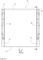
- the garage door 10 comprises a fixed frame 11 mounted in the opening 1 and formed of two side uprights 12, an upper crosspiece 13 and a threshold 14. It comprises a tilting closure panel 15, movable between a closed position to close said opening 1 (not shown) and an open position to completely clear it (cf. Figures 5 to 7 ).
- the shutter panel 15 is connected to the fixed frame 11 by two motion transmission mechanisms which each comprise a main lever 16 fixed to said shutter panel 15 by a joint 17, and provided with a rotation shaft 18 mounted in rotation in the lateral uprights 12 of the fixed frame 11 by bearings 19.
- Two compensation mechanisms 20 are also provided in the side uprights 12 and are connected to the main levers 16 via their rotation shaft 18, to balance the weight of the shutter panel 15 during its movements.
- These compensation mechanisms 20 may consist of tension springs 21 (cf. Figures 5 to 7 ), gas cylinders or any other equivalent member, numbering one, two, three or even more depending on the weight of the closure panel 15.
- These members are arranged parallel to each other and extend between the fixed frame 11 and the rotation shaft 18 of the main levers 16 to which they are connected respectively, at a first end 20a, by a first attachment piece 22, and at a second end 20b, by a second attachment piece 26.
- a fixing lug 23 is welded to the rotation shaft 18 and coupled to the corresponding first attachment piece 22 by a joint 24.
- the garage door 10 comprises a motor 30 for automating the operations of the shutter panel 15.
- the motor 30 comprises two motors 31, each mounted in a side upright 12, preferably such that their output shaft 32 is parallel to the rotation shaft 18 of the main lever 16 and coupled to the latter by a mechanical transmission 33.
- the motors 31 may be geared motors, stepper motors, or any other equivalent type of actuator, such as rotary or linear cylinders. They may be powered by the mains and are preferably controlled by an electronic card in a control box 37.
- the mechanical transmission 33 comprises in the example shown a drive pinion 34 provided on the output shaft 32 of each motor 31 driving a receiving pinion 35 provided on the rotation shaft 18 by a chain 36.
- any other type of equivalent mechanical transmission may be suitable, such as a pulley-belt system, a pinion-rack system, a connecting rod-arm system.
- the motorization 30 comprises for each of the lateral uprights 12 of the fixed frame 11, a specific motor support 40 constituting a subassembly of the garage door 1.
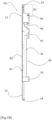
- the motor support 40 is designed in a standard manner and comprises a support profile 41.
- the support profile 41 the section of which may be U-shaped, is configured to support the first attachment part 22 of the compensation mechanism 20, and the second attachment part 26 of the compensation mechanism 20, and preferably all of the constituent parts of the motorization 30, such as the motor 31, the bearing 19 for the rotation shaft 18, the mechanical transmission 33, and possibly the control box 37.
- the motor 31, the bearing 19 for the rotation shaft 18, the mechanical transmission 33, possibly the control box 37, the first attachment part 22 of the compensation mechanism 20, and the second attachment part 26 of the compensation mechanism 20, can then be fixed directly to the support profile 41, which is a single piece.
- the support profile 41 is preferably rectilinear, and of a length less than the height of the side uprights 12.
- the support profile 41 advantageously has a U-shaped section delimiting a bottom 42 and two side walls 43 perpendicular to the bottom.
- the bottom 42 of the support profile 41 may comprise a plurality of oblong orifices 44 and fixing holes 45, distributed in the height and in the width of the profile, the function of which will be described below.
- the second attachment part 26 is a corner piece comprising three holes, for the possible fixing of three springs 21.
- the corner piece 26 is fixed to the support profile 41 by means of a threaded rod and bolts, the position of the bolts on the rod making it possible to adjust the tension of the springs 21.
- the side walls 43 of the support profile 41 may comprise, in the upper half, parallel cutouts 46 and 47 in pairs, to allow the passage and maintenance respectively of the output shaft 32 of the motor 31 and the rotation shaft 18 of the closure panel 15. They may comprise holes 48 for fixing the motor 31 and the bearings 19, and orifices 49 for spacers 50.
- the side walls 43 of the support profile 41 may comprise, in the lower part, parallel cheeks 51 for receiving the fixing of the second attachment part 26 of the compensation mechanism 20.
- the side wall 43 on the outside of the garage door 1 may further comprise projecting fixing lugs 52, provided with oblong holes 44, and obtained by cutting out the corresponding side wall 43.
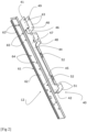
- the side uprights 12 of the fixed frame 11 are also specific and arranged to cooperate with the engine supports 40. In a preferred embodiment, they are designed in a standard manner and each form a housing for receiving an engine support 40. They then each comprise a straight upright profile 61 extending over the entire height of the fixed frame 11.
- the upright profile 61 may have a U-shaped section delimiting a bottom 62 and two side walls 63 perpendicular to the bottom.
- the section of the upright profile 61 is preferably complementary to the section of the support profile 41 to allow assembly by nesting and sliding of the support profile 41 inside the upright profile 61.
- the bottom 62 of the upright profile 61 may comprise a plurality of oblong orifices 64 and fixing holes 65, distributed in the height and width of the profile, arranged to cooperate with the oblong orifices 44 and the fixing holes 45 of the motor support 40.
- the oblong orifices 44, 64 allow compensation for manufacturing and/or mounting tolerances.
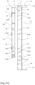
- the different mounting positions may be determined by the specifications of the garage door 10, and in particular its height, its width, and the thickness of the external insulating coating 15'.
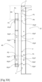
- FIGS. 3A to 3D illustrate different mounting positions as well as the combination between the different oblong holes 44, 64 and fixing holes 45, 65 making it possible to obtain these different mounting positions, which are locked by fixing means, such as screws or the like (not shown).
- FIG. 3A corresponds to a first mounting position, in which the upper dimension D1 which extends between the axis of the spacer 50 and the top of the fixed frame 11 is for example equal to 265mm.
- the orifices and holes used are identified by the legend P1 and/or by the legend F if they are used to fix the fixed frame 11 in the masonry.
- FIG. 3B corresponds to a second mounting position, in which the upper dimension D2 is greater than D1 and for example equal to 315 mm.
- the orifices and holes used are identified by the legend P2 or P1 depending on whether they are suitable for both the first and/or second positions, and/or by the legend F if they are used to fix the fixed frame 11 in the masonry.
- FIG. 3C corresponds to a third mounting position, in which the upper dimension D3 is greater than D2 and for example equal to 415 mm.
- the orifices and holes used are identified by the legend P3 or P2 or P1 depending on whether they are suitable for both the first, second and/or third positions, and/or by the legend F if they are used to fix the fixed frame 11 in the masonry.
- 3D figure corresponds to a fourth mounting position, in which the upper dimension D4 is greater than D3 and for example equal to 465 mm.
- the orifices and holes used are identified by the legend P4 or P3 or P2 or P1 depending on whether they are suitable for both the first, second, third and/or fourth positions, and/or by the legend F if they are used to fix the fixed frame 11 in the masonry.
- the values mentioned for D1, D2, D3 and D4 are given as examples and are not limiting.
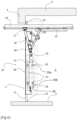
- FIG 5 shows an example of the installation of a garage door 10 in an opening 1 of a garage entrance 2, the fixed frame 11 being surface-mounted at the rear of the projection 5 of the masonry.
- the position illustrated may correspond to the first mounting position described with reference to the Figure 3A according to the D1 rating.
- the figure 6 shows the same example of the layout of garage door 10 as that of the figure 5 .
- the shutter panel 15 has a coating exterior insulation 15' thicker than that of the figure 5 , requiring lowering the mounting position of the motorization 30, for example by choosing the second mounting position described with reference to the Figure 3B according to the D2 rating.
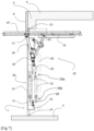
- the figure 7 shows another example of the installation of a garage door 10 in an opening 1 of a garage entrance 2, the fixed frame 11 being placed in a tunnel at the level of the drop 5 of the masonry.
- the position illustrated may correspond to the first mounting position described with reference to the Figure 3A according to dimension D1.
- the exterior insulating covering 15' of the garage door 10 is flush with the covering of the facade of the building, to obtain a more contemporary aesthetic for the garage door 10.
- the side uprights 12 of the fixed frame 11 are completed, on the inside of the garage 2, by a cover 25 to protect the moving parts, whether the frame is surface-mounted, as shown for example in figures 5 And 6 , or in a tunnel, as shown in the figure 7 .
- the invention allows standardization and modularity of the tilting garage door 10.
- the support of the two ends 20a, 20b of the compensation mechanism 20 by a single part has the technical effect of significantly increasing the rigidity of the fixed frame 11, allowing it to better withstand the forces generated by the compensation mechanism 20 during the opening and closing movements of the garage door 10.
- the invention thus makes it possible to propose garage doors 10 that are technically more reliable, lighter, while being more rigid, also suitable for openings 1 of great heights and/or great widths. It also offers the possibility of filling the closure panel 15 with a thick external insulating coating 15' without mechanical modification, the position of the closure panel being able to be lowered.
- the invention thus makes it possible to industrialize the garage door 10 as a whole, to produce a finished thermo-lacquered product, to pre-equip the motor support 40 with a motorization 30 integrated into the fixed frame 11, and to add the compensation mechanism 20.
Landscapes
- Engineering & Computer Science (AREA)
- Mechanical Engineering (AREA)
- Power-Operated Mechanisms For Wings (AREA)
- Operating, Guiding And Securing Of Roll- Type Closing Members (AREA)
Applications Claiming Priority (1)
| Application Number | Priority Date | Filing Date | Title |
|---|---|---|---|
| FR2304188A FR3148251A1 (fr) | 2023-04-26 | 2023-04-26 | Porte de garage basculante à motorisation intégrée dans le cadre fixe |
Publications (3)
| Publication Number | Publication Date |
|---|---|
| EP4455433A1 true EP4455433A1 (de) | 2024-10-30 |
| EP4455433B1 EP4455433B1 (de) | 2025-07-23 |
| EP4455433C0 EP4455433C0 (de) | 2025-07-23 |
Family
ID=87554465
Family Applications (1)
| Application Number | Title | Priority Date | Filing Date |
|---|---|---|---|
| EP24157179.3A Active EP4455433B1 (de) | 2023-04-26 | 2024-02-12 | Garagenschwenktor mit im festen rahmen integrierter motorisierung |
Country Status (2)
| Country | Link |
|---|---|
| EP (1) | EP4455433B1 (de) |
| FR (2) | FR3148251A1 (de) |
Citations (3)
| Publication number | Priority date | Publication date | Assignee | Title |
|---|---|---|---|---|
| EP0952293B1 (de) * | 1998-04-24 | 2002-07-03 | Albert Moos | Überkopfschwingtor des Drehbewegungstyps mit Seiten(gas)federn |
| FR2871189B1 (fr) | 2004-06-08 | 2007-01-19 | Albert Moos | Dispositif d'entrainement automatique pour porte basculante du type a deplacement circulaire et porte basculante equipee d'un tel dispositif |
| FR2928168A1 (fr) * | 2008-02-29 | 2009-09-04 | Andre Remonato | Appareil sous forme de carter comprenant les mecanismes d'equilibrage, de pivotement et de suspension d'une porte basculante prevue a etre motorisee avec systeme de verrouillage et deverrouillage automatique a multifonctions. |
-
2023
- 2023-04-26 FR FR2304188A patent/FR3148251A1/fr not_active Ceased
-
2024
- 2024-02-12 FR FR2401324A patent/FR3148250B1/fr active Active
- 2024-02-12 EP EP24157179.3A patent/EP4455433B1/de active Active
Patent Citations (3)
| Publication number | Priority date | Publication date | Assignee | Title |
|---|---|---|---|---|
| EP0952293B1 (de) * | 1998-04-24 | 2002-07-03 | Albert Moos | Überkopfschwingtor des Drehbewegungstyps mit Seiten(gas)federn |
| FR2871189B1 (fr) | 2004-06-08 | 2007-01-19 | Albert Moos | Dispositif d'entrainement automatique pour porte basculante du type a deplacement circulaire et porte basculante equipee d'un tel dispositif |
| FR2928168A1 (fr) * | 2008-02-29 | 2009-09-04 | Andre Remonato | Appareil sous forme de carter comprenant les mecanismes d'equilibrage, de pivotement et de suspension d'une porte basculante prevue a etre motorisee avec systeme de verrouillage et deverrouillage automatique a multifonctions. |
Also Published As
| Publication number | Publication date |
|---|---|
| EP4455433B1 (de) | 2025-07-23 |
| FR3148250B1 (fr) | 2026-02-13 |
| EP4455433C0 (de) | 2025-07-23 |
| FR3148250A1 (fr) | 2024-11-01 |
| FR3148251A1 (fr) | 2024-11-01 |
Similar Documents
| Publication | Publication Date | Title |
|---|---|---|
| FR2926263A1 (fr) | Glissiere pour siege de vehicule et siege de vehicule comprenant une telle glissiere. | |
| FR2948718A1 (fr) | Structure de menuiserie a poser au niveau d'une baie de batiment munie d'un coffre superieur demi-linteau | |
| EP4455433B1 (de) | Garagenschwenktor mit im festen rahmen integrierter motorisierung | |
| EP2206869B1 (de) | Vorrichtung für die Motorisierung eines Fensters oder des Öffnungselements eines Schiebefensters | |
| EP2709940A1 (de) | Lastenhebevorrichtung | |
| EP4269741A1 (de) | Rolladenkasten mit zugang zu der vorderseite | |
| EP1369549B1 (de) | Selbsttragendes Türblatt für ein Kipptor | |
| EP2053189A2 (de) | Rahmen mit Fenster- oder Türflügel | |
| FR2715690A1 (fr) | Agencement de support pivotant d'un ouvrant à une partie fixe formant dormant. | |
| FR2997914A1 (fr) | Table pliante avec moyens de liaison pivot du type a maillons | |
| EP1160414A1 (de) | Endhalterung für eine Wickelwelle, Verfahren zur Herstellung und Antriebsmechanismus einer Schliess- oder Sonnenschutzeinrichtung mit solcher Vorrichtung | |
| WO2018134491A1 (fr) | Dispositif d'obturation d'entree d'air de face avant de vehicule automobile et procede de fabrication | |
| FR2697112A1 (fr) | Ensemble profilé pour le câblage d'appareillages électriques dans une paroi, et ossature et goulotte propres à la constitution d'un tel ensemble profilé. | |
| FR3113297A1 (fr) | Coffre de volet roulant équipé d’une structure longitudinale de renfort intérieure | |
| EP2172382A1 (de) | Schienenfahrzeug Wagenkasten und entsprechendes Herstellungsverfahren | |
| EP3173564B1 (de) | Rahmen für klappladen | |
| FR3152527A1 (fr) | Portail coulissant sans traverse | |
| EP0876945B1 (de) | Türblattbefestigungsvorrichtung, damit versehene Tür und damit ausgerüstetes Schienfahrzeug | |
| EP4678869A1 (de) | Schutzvorrichtung für eine gebäudeöffnung, zum aufnehmen eines schutzschirms, z.b. eines rollladenpanzers | |
| FR2800414A1 (fr) | Structure de boitier pour porte coulissante | |
| FR2944312A1 (fr) | Ensemble de menuiserie pour equiper une baie de batiment, du genre fenetre a guillotine | |
| EP0320423A1 (de) | Rolladenkasten | |
| FR3129968A1 (fr) | Dispositif d’obstruction de passage et portillon d’accès associé | |
| FR3102453A1 (fr) | Systeme de montage d’une porte d’acces pour un caisson de vehicule automobile | |
| EP4678868A1 (de) | Rack-block-anordnung |
Legal Events
| Date | Code | Title | Description |
|---|---|---|---|
| PUAI | Public reference made under article 153(3) epc to a published international application that has entered the european phase |
Free format text: ORIGINAL CODE: 0009012 |
|
| STAA | Information on the status of an ep patent application or granted ep patent |
Free format text: STATUS: THE APPLICATION HAS BEEN PUBLISHED |
|
| AK | Designated contracting states |
Kind code of ref document: A1 Designated state(s): AL AT BE BG CH CY CZ DE DK EE ES FI FR GB GR HR HU IE IS IT LI LT LU LV MC ME MK MT NL NO PL PT RO RS SE SI SK SM TR |
|
| STAA | Information on the status of an ep patent application or granted ep patent |
Free format text: STATUS: REQUEST FOR EXAMINATION WAS MADE |
|
| 17P | Request for examination filed |
Effective date: 20250109 |
|
| GRAP | Despatch of communication of intention to grant a patent |
Free format text: ORIGINAL CODE: EPIDOSNIGR1 |
|
| STAA | Information on the status of an ep patent application or granted ep patent |
Free format text: STATUS: GRANT OF PATENT IS INTENDED |
|
| GRAJ | Information related to disapproval of communication of intention to grant by the applicant or resumption of examination proceedings by the epo deleted |
Free format text: ORIGINAL CODE: EPIDOSDIGR1 |
|
| GRAP | Despatch of communication of intention to grant a patent |
Free format text: ORIGINAL CODE: EPIDOSNIGR1 |
|
| INTG | Intention to grant announced |
Effective date: 20250429 |
|
| GRAS | Grant fee paid |
Free format text: ORIGINAL CODE: EPIDOSNIGR3 |
|
| GRAA | (expected) grant |
Free format text: ORIGINAL CODE: 0009210 |
|
| STAA | Information on the status of an ep patent application or granted ep patent |
Free format text: STATUS: THE PATENT HAS BEEN GRANTED |
|
| AK | Designated contracting states |
Kind code of ref document: B1 Designated state(s): AL AT BE BG CH CY CZ DE DK EE ES FI FR GB GR HR HU IE IS IT LI LT LU LV MC ME MK MT NL NO PL PT RO RS SE SI SK SM TR |
|
| REG | Reference to a national code |
Ref country code: GB Ref legal event code: FG4D Free format text: NOT ENGLISH |
|
| REG | Reference to a national code |
Ref country code: CH Ref legal event code: EP |
|
| REG | Reference to a national code |
Ref country code: IE Ref legal event code: FG4D Free format text: LANGUAGE OF EP DOCUMENT: FRENCH |
|
| U01 | Request for unitary effect filed |
Effective date: 20250723 |
|
| U07 | Unitary effect registered |
Designated state(s): AT BE BG DE DK EE FI FR IT LT LU LV MT NL PT RO SE SI Effective date: 20250729 |
|
| PG25 | Lapsed in a contracting state [announced via postgrant information from national office to epo] |
Ref country code: IS Free format text: LAPSE BECAUSE OF FAILURE TO SUBMIT A TRANSLATION OF THE DESCRIPTION OR TO PAY THE FEE WITHIN THE PRESCRIBED TIME-LIMIT Effective date: 20251123 |
|
| PG25 | Lapsed in a contracting state [announced via postgrant information from national office to epo] |
Ref country code: NO Free format text: LAPSE BECAUSE OF FAILURE TO SUBMIT A TRANSLATION OF THE DESCRIPTION OR TO PAY THE FEE WITHIN THE PRESCRIBED TIME-LIMIT Effective date: 20251023 |
|
| PG25 | Lapsed in a contracting state [announced via postgrant information from national office to epo] |
Ref country code: HR Free format text: LAPSE BECAUSE OF FAILURE TO SUBMIT A TRANSLATION OF THE DESCRIPTION OR TO PAY THE FEE WITHIN THE PRESCRIBED TIME-LIMIT Effective date: 20250723 |
|
| PG25 | Lapsed in a contracting state [announced via postgrant information from national office to epo] |
Ref country code: GR Free format text: LAPSE BECAUSE OF FAILURE TO SUBMIT A TRANSLATION OF THE DESCRIPTION OR TO PAY THE FEE WITHIN THE PRESCRIBED TIME-LIMIT Effective date: 20251024 |
|
| PG25 | Lapsed in a contracting state [announced via postgrant information from national office to epo] |
Ref country code: PL Free format text: LAPSE BECAUSE OF FAILURE TO SUBMIT A TRANSLATION OF THE DESCRIPTION OR TO PAY THE FEE WITHIN THE PRESCRIBED TIME-LIMIT Effective date: 20250723 |
|
| PG25 | Lapsed in a contracting state [announced via postgrant information from national office to epo] |
Ref country code: RS Free format text: LAPSE BECAUSE OF FAILURE TO SUBMIT A TRANSLATION OF THE DESCRIPTION OR TO PAY THE FEE WITHIN THE PRESCRIBED TIME-LIMIT Effective date: 20251023 |
|
| PG25 | Lapsed in a contracting state [announced via postgrant information from national office to epo] |
Ref country code: ES Free format text: LAPSE BECAUSE OF FAILURE TO SUBMIT A TRANSLATION OF THE DESCRIPTION OR TO PAY THE FEE WITHIN THE PRESCRIBED TIME-LIMIT Effective date: 20250723 |
|
| U20 | Renewal fee for the european patent with unitary effect paid |
Year of fee payment: 3 Effective date: 20260219 |