EP4454841A1 - Rotationsschneideinheit - Google Patents
Rotationsschneideinheit Download PDFInfo
- Publication number
- EP4454841A1 EP4454841A1 EP24169356.3A EP24169356A EP4454841A1 EP 4454841 A1 EP4454841 A1 EP 4454841A1 EP 24169356 A EP24169356 A EP 24169356A EP 4454841 A1 EP4454841 A1 EP 4454841A1
- Authority
- EP
- European Patent Office
- Prior art keywords
- pair
- roll
- rotatably
- supporting portions
- air springs
- Prior art date
- Legal status (The legal status is an assumption and is not a legal conclusion. Google has not performed a legal analysis and makes no representation as to the accuracy of the status listed.)
- Granted
Links
Images


Classifications
-
- B—PERFORMING OPERATIONS; TRANSPORTING
- B26—HAND CUTTING TOOLS; CUTTING; SEVERING
- B26D—CUTTING; DETAILS COMMON TO MACHINES FOR PERFORATING, PUNCHING, CUTTING-OUT, STAMPING-OUT OR SEVERING
- B26D7/00—Details of apparatus for cutting, cutting-out, stamping-out, punching, perforating, or severing by means other than cutting
- B26D7/26—Means for mounting or adjusting the cutting member; Means for adjusting the stroke of the cutting member
- B26D7/2628—Means for adjusting the position of the cutting member
- B26D7/265—Journals, bearings or supports for positioning rollers or cylinders relatively to each other
-
- B—PERFORMING OPERATIONS; TRANSPORTING
- B26—HAND CUTTING TOOLS; CUTTING; SEVERING
- B26F—PERFORATING; PUNCHING; CUTTING-OUT; STAMPING-OUT; SEVERING BY MEANS OTHER THAN CUTTING
- B26F1/00—Perforating; Punching; Cutting-out; Stamping-out; Apparatus therefor
- B26F1/38—Cutting-out; Stamping-out
- B26F1/40—Cutting-out; Stamping-out using a press, e.g. of the ram type
- B26F1/42—Cutting-out; Stamping-out using a press, e.g. of the ram type having a pressure roller
-
- B—PERFORMING OPERATIONS; TRANSPORTING
- B26—HAND CUTTING TOOLS; CUTTING; SEVERING
- B26D—CUTTING; DETAILS COMMON TO MACHINES FOR PERFORATING, PUNCHING, CUTTING-OUT, STAMPING-OUT OR SEVERING
- B26D1/00—Cutting through work characterised by the nature or movement of the cutting member or particular materials not otherwise provided for; Apparatus or machines therefor; Cutting members therefor
- B26D1/01—Cutting through work characterised by the nature or movement of the cutting member or particular materials not otherwise provided for; Apparatus or machines therefor; Cutting members therefor involving a cutting member which does not travel with the work
- B26D1/12—Cutting through work characterised by the nature or movement of the cutting member or particular materials not otherwise provided for; Apparatus or machines therefor; Cutting members therefor involving a cutting member which does not travel with the work having a cutting member moving about an axis
- B26D1/25—Cutting through work characterised by the nature or movement of the cutting member or particular materials not otherwise provided for; Apparatus or machines therefor; Cutting members therefor involving a cutting member which does not travel with the work having a cutting member moving about an axis with a non-circular cutting member
- B26D1/34—Cutting through work characterised by the nature or movement of the cutting member or particular materials not otherwise provided for; Apparatus or machines therefor; Cutting members therefor involving a cutting member which does not travel with the work having a cutting member moving about an axis with a non-circular cutting member moving about an axis parallel to the line of cut
- B26D1/40—Cutting through work characterised by the nature or movement of the cutting member or particular materials not otherwise provided for; Apparatus or machines therefor; Cutting members therefor involving a cutting member which does not travel with the work having a cutting member moving about an axis with a non-circular cutting member moving about an axis parallel to the line of cut and coacting with a rotary member
-
- B—PERFORMING OPERATIONS; TRANSPORTING
- B26—HAND CUTTING TOOLS; CUTTING; SEVERING
- B26F—PERFORATING; PUNCHING; CUTTING-OUT; STAMPING-OUT; SEVERING BY MEANS OTHER THAN CUTTING
- B26F1/00—Perforating; Punching; Cutting-out; Stamping-out; Apparatus therefor
- B26F1/18—Perforating by slitting, i.e. forming cuts closed at their ends without removal of material
- B26F1/20—Perforating by slitting, i.e. forming cuts closed at their ends without removal of material with tools carried by a rotating drum or similar support
-
- B—PERFORMING OPERATIONS; TRANSPORTING
- B26—HAND CUTTING TOOLS; CUTTING; SEVERING
- B26F—PERFORATING; PUNCHING; CUTTING-OUT; STAMPING-OUT; SEVERING BY MEANS OTHER THAN CUTTING
- B26F1/00—Perforating; Punching; Cutting-out; Stamping-out; Apparatus therefor
- B26F1/38—Cutting-out; Stamping-out
- B26F1/384—Cutting-out; Stamping-out using rotating drums
Definitions
- the present invention relates to a rotary cutter unit for continuously cutting a thin strip-shaped material such as a nonwoven fabric or a film into a given shape.
- a rotary cutter unit is used to cut a thin strip-shaped material into a given shapes.
- the rotary cutter unit comprises: a cutter roll comprising a cutting blade having a cutting geometry; and an anvil roll comprising a receiving part for the cutting blader.
- the cutter roll and the anvil roll are arranged in parallel, and rotated in opposite directions while being kept in closely-adjacent or contact relation to each other, whereby the rotary cutter unit can continuously press-cut the material.
- Patent Document 1 discloses a rotary cutting device configured to reduce impact-caused vibration of a drum such as an anvil drum or a cutter drum, through the use of vibration attenuating means equipped with a passive damper as an elastic member.
- Patent Document 2 discloses a rotary working device in which an actuator is provided outside a cutting unit, thereby making it possible to: suppress vibration; reduce the height dimension of a frame of the cutting unit to lower the center of gravity of the cutting unit; and facilitate replacement of the cutting unit.
- Patent Document 3 discloses a printing/cutting apparatus using an air spring aiming at fine adjustment of pressure.
- Patent Documents 4 and 5 disclose air springs for rotary cutters, aiming at adjusting the positions of a knife rotor and a plane rotor.
- the passive damper used in the rotary cutting device disclosed in the Patent Document 1 can quickly reduce vibration caused by impact at the time of collision of a movable roll against a fixed roll.
- the passive damper cannot suppress the occurrence of the impact itself, nor can it suppress the external vibration.
- this rotary cutting device uses a relatively large number of components due to the use of a plurality of elastic members as the passive damper, etc., which is likely to lead to structural complication, resulting in not only complicated disassembling and reassembling work during roll replacement but also increased cost.
- vibration can be suppressed by using the actuator installed outside the cutting unit to bring a movable roll into contact with a fixed roll.
- the actuator cannot suppress the occurrence of impact itself, which is likely to lead to chipping of a cutting blade.
- the actuator cannot completely absorb external vibration transmitted to the cutting unit.
- the present invention addresses a technical problem of providing a structurally simplified rotary cutter unit capable of suppressing impact to be received by two rolls consisting of a cutter roll and an anvil roll, while allowing the two rolls to avoid receiving vibration directly from the outside, thereby preventing chipping of a cutting edge of a cutting blade of the cutter roll and damage to the surface of the anvil roll, and maintaining cutting performance over a long period of time.
- the present invention provides a rotary cutter unit comprising: a cutter roll comprising a roll body having an outer circumferential surface, and a cutting blade positioned at the outer circumferential surface, the cutting blade having a cutting geometry; an anvil roll disposed parallel to the cutter roll, the anvil roll comprising a roll body having an outer circumferential surface configured to receive the cutting blade; a pair of rotatably-supporting portions each disposed at a respective one of opposite ends of the cutter roll; a pair of rotatably-supporting portions each disposed at a respective one of opposite ends of the anvil roll; a pair of air springs A each installed to apply pressure to a respective one of the pair of rotatably-supporting portions of one of two rolls consisting of the cutter roll and the anvil roll; and a pair of spring means B each installed to apply pressure to a respective one of the pair of rotatably-supporting portions of the other roll, in a direction opposed to a direction of the pressure application of the pair
- the rotary cutter unit may further comprises a pair of air springs C installed between the pair of rotatably-supporting portions of the cutter roll and the pair of rotatably-supporting portions of the anvil roll, to apply pressure to at least one of the pair of rotatably-supporting portions of the cutter roll and the pair of rotatably-supporting portions of the anvil roll, in a direction along a direction which causes the pressure applied from the pair of air springs A to increase or decrease.
- the pair of spring means B may be composed of a pair of air springs.
- impact to be received by the two rolls can be suppressed by using the pair of air springs and the pair of spring means to apply pressures to respective corresponding ones of the two pairs of rotatably-supporting portions in opposite directions sandwiching the two rolls. It is also possible to suppress impact caused by a collision of the two rolls, etc. Further, it becomes possible to prevent the two rolls from receiving vibration directly from the outside. This makes it possible to prevent chipping of a cutting edge of the cutting blade of the cutter roll and damage to the surface of the anvil roll, thereby maintaining cutting performance over a long period of time.
- a rotary cutter unit of the present invention has the following configuration.
- the rotary cutter unit comprises:
- FIGS. 1A and 1B the details of the configuration of the rotary cutter unit of the present invention will now be described.
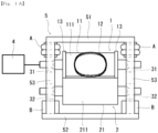
- a cutter roll 1 comprises a roll body 11 having an outer circumferential surface 111, and a cutting blade 12 positioned at the outer circumferential surface 111 and having a desired cutting geometry.
- the cutter roll 1 further comprises a pair of guide rings 13 provided on both sides of the cutting blade 12. The height dimension of each of the guide rings 13 is set to be substantially equal to a distance from the outer circumferential surface 111 to a cutting edge of the cutting blade 12.
- An anvil roll 2 comprises a roll body 21 having an outer circumferential surface 211.
- the anvil roll 2 is disposed parallel to the cutter roll 1, so that the outer circumferential surface 211 of the anvil roll 2 can receive the cutting blade 12 of the cutter roll 1.
- a pair of rotatably-supporting portions 31 are provided to rotatably hold opposite ends of the cutter roll 1, respectively, and a pair of rotatably supporting portion 32 is provided to rotatably hold opposite ends of the anvil roll 2, respectively.
- a drive unit 4 is configured to rotationally drive at least one of the cutter roll 1 and the anvil roll 2 (in FIG. 1A , one end (one of the opposite ends) of the cutter roll 1).
- the drive unit 4 may be a servomotor. It should be noted that the drive unit 4 is omitted in FIG. 1B .
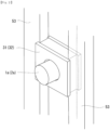
- a pair of air springs A are installed to apply pressure, respectively, to the pair of rotatably-supporting portions of one of the two rolls 1, 2, which is rotationally driven by the drive unit 4, in a direction which causes respective centers of the two rolls 1, 2 to linearly come close to or come into contact with each other.
- the pair of air springs A are installed to apply pressure, respectively, to the pair of rotatably-supporting portions 31 of the roll rotationally driven by the drive unit 4.
- the pair of air springs A may be installed to apply pressure, respectively, to the pair of rotatably-supporting portions 32 of the other, roll which is not rotationally driven by the drive unit 4.
- the pair of air springs A are installed to apply pressure, respectively, to the pair of rotatably-supporting portions at the opposite ends of one of the two rolls 1, 2. Based on the above configuration, the pair of air springs A can apply pressure to the two rolls 1, 2. Further, each of the air springs A can deform in response to external force to attenuate vibration.
- a pair of spring means B are installed to apply pressure, respectively, to the pair of rotationally-supporting portions 32 of the other, roll to which the pair of air springs A are not installed, in a direction opposed to a direction of the pressure application of the pair of air springs A.
- the spring means B may be an oil-hydraulic cylinder, a pneumatic (air) cylinder, or an air spring.
- Each rotatably-supporting portion of the pair of rotatably-supporting portions 31 rotatably holding the opposite ends of the cutter roll 1 and the pair of rotatably-supporting portions 32 rotatably holding the opposite ends of the anvil roll 2 is slidable in directions which cause the pressure applied from a corresponding one of the pair of air springs A and the pair of spring means B to increase and decrease.
- the pair of air springs A and the pair of spring means B are installed to apply pressures to respective corresponding ones of the pairs of rotatably-supporting portions 31, 32 in opposite directions sandwiching the two rolls 1, 2, and each rotatably-supporting portion of the pairs of rotatably-supporting portions 31, 32 is installed slidably in directions which cause the pressure applied from a corresponding one of the pair of air springs A and the pair of spring means B to increase and decrease, whereby the pair of air springs A and the pair of spring means B can attenuate vibration generated between the two rolls 1, 2.
- the vibration attenuating effect of the pair of air springs A is higher than that of a commonly-used spring means (such as an oil-hydraulic cylinder or a pneumatic cylinder).
- the spring means B even when an oil-hydraulic cylinder or a pneumatic cylinder is employed as the spring means B, it can be slightly retracted (contracted) in response to external force to attenuate vibration, although inferior to the air spring A.
- the pair of spring means B may be composed of a pair of air springs.
- applying pressures to respective corresponding ones of the pairs of rotatably-supporting portions in opposite directions sandwiching the two rolls means that the pair of air springs A and the pair of spring means B apply pressures to respective corresponding ones of the pairs of rotatably-supporting portions of the two rolls, in directions which cause the cutter roll and the anvil roll to linearly come close to or come into contact with each other.
- being slidable in directions which cause the pressure applied from a corresponding one of the pair of air springs A and the pair of spring means B to increase and decrease means that when the pressure applied from a corresponding one of the pair of air springs A and the pair of spring means B increases or decreases, the two rolls can move in directions which cause them to linearly come close to or away from each other.
- the rotary cutter unit may comprise a pair of air springs C installed between the pair of rotatably-supporting portions 31 of the cutter roll 1 and the pair of rotatably-supporting portions 32 of the anvil roll 2, to apply pressure to at least one of the pair of rotatably-supporting portions of the cutter roll and the pair of rotatably-supporting portions of the anvil roll, in a direction along a direction which causes the pressure applied from the pair of air springs A to increase or decrease.
- This configuration is more effective in suppressing impact between the two rolls during operation and attenuating external vibration.
- FIG. 1A is a front view schematically showing an exemplary configuration of a rotary cutter unit according to a first embodiment of the present invention
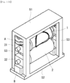
- FIG. 1B is a schematic perspective view of the rotary cutter unit.
- the rotary cutter unit comprises a cutter unit frame 5, a cutter roll 1, an anvil roll 2, two pairs of rotatably-supporting portions 31, 32, a drive unit 4, a pair of air springs A, and a pair of spring means B each composed of a pneumatic cylinder.
- the cutter unit frame 5 comprises a top plate 51, a bottom plate 52, and plural pillars 53.
- the cutter roll 1 and the anvil roll 2 are arranged inside the cutter unit frame 5.
- Each rotatably-supporting portion of the two pairs of rotatably-supporting portions 31, 32 is composed of a bearing box, and a pair of bearing boxes 31 and a pair of bearing boxes 32 are provided, respectively, to the cutter roll 1 and the anvil roll 2.
- the pair of air springs A and the pair of spring means B are installed to apply pressures to respective corresponding ones of the pairs of bearing boxes as the pairs of rotatably-supporting portions in directions sandwiching the two rolls 1, 2.
- the pair of air springs A are installed to apply pressure, respectively, to the pair of bearing boxes 31 at respective opposite ends of the cutter roll 1 provided with the drive unit 4, and the pair of spring means B are installed to apply pressure, respectively, to the pair of bearing boxes 32 at respective opposite ends of the anvil roll 2.
- the pair of spring means B are installed to apply pressure, respectively, to the pair of bearing boxes 32 in a direction opposite to a direction of the pressure application of the pair of air springs A.
- each of the bearing boxes 31, 32 is installed slidably in directions which cause the pressure applied from a corresponding one of the pair of air springs A and the pair of spring means B to increase and decrease.
- each of the bearing boxes 31, 32 is installed slidably along two of the pillars 53 of the cutter unit frame 5.
- the reference signs 1a, 2a denote, respectively, one end of the cutter roll 1 and one end of the anvil roll 2.
- an upper limit stopper and a lower limit stopper may be provided to define an upper limit position and a lower limit position of a sliding movement of each of the bearing boxes 31, 32, respectively.
- a vibration meter with an acceleration sensor was mounted to each rotatably-supporting portion (bearing box) in the rotary cutter unit according to the first embodiment and the conventional rotary cutter unit in FIG. 5 , to measure vibration for one minute.
- the rotary cutter unit according to the first embodiment could reduce the maximum value of vibration amplitude by 30% as compared to the rotary cutter unit having the configuration in FIG. 5 .
- FIG. 3 is a front view schematically showing an exemplary configuration of a rotary cutter unit according to a second embodiment of the present invention.
- the rotary cutter unit according to the second embodiment comprises a pair of air springs C.
- This pair of air springs C are installed between the pair of rotatably-supporting portions 31 of the cutter roll 1 and the pair of rotatably-supporting portions 32 of the anvil roll 2, to apply pressures to respective ones of the pairs of rotatably-supporting portions 31, 32, in directions along respective directions which cause the pressure applied from the pair of air springs A to increase and decrease.
- the pair of air springs C are configured and installed to apply pressures to both the pair of rotatably-supporting portions 31 and the pair of rotatably-supporting portions 32.
- the pair of air springs C may be configured and installed to apply pressure to at least one of the pair of rotatably-supporting portions 31 and the pair of rotatably-supporting portions 32.
- the pair of air springs C is provided in addition to pair of the air springs A and the pair of spring means B, so that it becomes possible to enhance the vibration attenuation effect.
- a vibration meter with an acceleration sensor was mounted to each rotatably-supporting portion (bearing box) in the rotary cutter unit according to the second embodiment and the conventional rotary cutter unit in FIG. 5 , to measure vibration for one minute.
- the rotary cutter unit according to the second embodiment could reduce the maximum value of vibration amplitude by 40% as compared to the rotary cutter unit having the configuration in FIG. 5 .
- FIG. 4 is a front view schematically showing an exemplary configuration of a rotary cutter unit according to a third embodiment of the present invention.
- the third embodiment is different from the first embodiment in that each of the pair of spring means B is composed of an air spring C. That is, in the first embodiment, a pneumatic cylinder is use as each of the pair of spring means B. In the third embodiment, the pneumatic cylinder is changed to an air spring.
- each of the pair of spring means B is composed of an air spring, so that it becomes possible to enhance the vibration attenuation effect.
- a vibration meter with an acceleration sensor was mounted to each rotatably-supporting portion (bearing box) in the rotary cutter unit according to the third embodiment and the conventional rotary cutter unit in FIG. 5 , to measure vibration for one minute.
- the rotary cutter unit according to the third embodiment could reduce the maximum value of vibration amplitude by 50% as compared to the rotary cutter unit having the configuration in FIG. 5 .
Landscapes
- Life Sciences & Earth Sciences (AREA)
- Forests & Forestry (AREA)
- Engineering & Computer Science (AREA)
- Mechanical Engineering (AREA)
- Perforating, Stamping-Out Or Severing By Means Other Than Cutting (AREA)
- Vibration Dampers (AREA)
- Fluid-Damping Devices (AREA)
Applications Claiming Priority (1)
| Application Number | Priority Date | Filing Date | Title |
|---|---|---|---|
| JP2023070596A JP7403021B1 (ja) | 2023-04-24 | 2023-04-24 | ロータリーカッターユニット |
Publications (2)
| Publication Number | Publication Date |
|---|---|
| EP4454841A1 true EP4454841A1 (de) | 2024-10-30 |
| EP4454841B1 EP4454841B1 (de) | 2025-10-01 |
Family
ID=89190414
Family Applications (1)
| Application Number | Title | Priority Date | Filing Date |
|---|---|---|---|
| EP24169356.3A Active EP4454841B1 (de) | 2023-04-24 | 2024-04-10 | Rotationsschneideinheit |
Country Status (3)
| Country | Link |
|---|---|
| US (1) | US20240351233A1 (de) |
| EP (1) | EP4454841B1 (de) |
| JP (1) | JP7403021B1 (de) |
Families Citing this family (1)
| Publication number | Priority date | Publication date | Assignee | Title |
|---|---|---|---|---|
| JP7796277B1 (ja) * | 2025-06-12 | 2026-01-08 | 日本タングステン株式会社 | モニタリングシステム |
Citations (8)
| Publication number | Priority date | Publication date | Assignee | Title |
|---|---|---|---|---|
| US4531929A (en) | 1982-08-19 | 1985-07-30 | Cortec, Wellpappenmaschinenhandelsund Service Gmbh | Apparatus for printing, punching and/or cutting to size unwound cardboard pieces |
| US5174185A (en) * | 1989-07-21 | 1992-12-29 | Wilhelm Aichele | Rotary cutting device for material webs |
| EP0547954B1 (de) * | 1991-12-16 | 1995-10-18 | Usinage Montage Et Assistance Technique U.M.A.T. | Rotationsstanzvorrichtung |
| JPH08112798A (ja) | 1994-10-17 | 1996-05-07 | Asahi Mach Kk | ロータリーカッター |
| JPH10138196A (ja) | 1996-11-06 | 1998-05-26 | Meisan Kk | ロータリーカッターのための接圧制御方法および装置 |
| JP2011156623A (ja) | 2010-02-01 | 2011-08-18 | Unicharm Corp | ロータリ加工装置 |
| JP2012218149A (ja) | 2011-04-08 | 2012-11-12 | Sandvik Intellectual Property Ab | 振動減衰手段を有する回転式切断装置 |
| CN107116613A (zh) * | 2016-02-24 | 2017-09-01 | 日本钨合金株式会社 | 旋转切裁装置用辊和旋转切裁装置 |
Family Cites Families (5)
| Publication number | Priority date | Publication date | Assignee | Title |
|---|---|---|---|---|
| DE10109933C1 (de) * | 2001-02-21 | 2002-08-22 | Aichele Werkzeuge Gmbh | Schneidvorrichtung und Schneidwerkzeug |
| JP2007268650A (ja) * | 2006-03-31 | 2007-10-18 | Nippon Tungsten Co Ltd | ダイカットロール |
| JP6645277B2 (ja) * | 2016-03-10 | 2020-02-14 | 三菱マテリアル株式会社 | ロータリーダイカッター |
| JP2017177300A (ja) * | 2016-03-31 | 2017-10-05 | 日本タングステン株式会社 | ロータリーカッターユニット |
| CN107984543A (zh) * | 2017-07-04 | 2018-05-04 | 江苏麒浩精密机械股份有限公司 | 一种旋转滚压模切装置 |
-
2023
- 2023-04-24 JP JP2023070596A patent/JP7403021B1/ja active Active
-
2024
- 2024-04-10 EP EP24169356.3A patent/EP4454841B1/de active Active
- 2024-04-22 US US18/641,625 patent/US20240351233A1/en active Pending
Patent Citations (8)
| Publication number | Priority date | Publication date | Assignee | Title |
|---|---|---|---|---|
| US4531929A (en) | 1982-08-19 | 1985-07-30 | Cortec, Wellpappenmaschinenhandelsund Service Gmbh | Apparatus for printing, punching and/or cutting to size unwound cardboard pieces |
| US5174185A (en) * | 1989-07-21 | 1992-12-29 | Wilhelm Aichele | Rotary cutting device for material webs |
| EP0547954B1 (de) * | 1991-12-16 | 1995-10-18 | Usinage Montage Et Assistance Technique U.M.A.T. | Rotationsstanzvorrichtung |
| JPH08112798A (ja) | 1994-10-17 | 1996-05-07 | Asahi Mach Kk | ロータリーカッター |
| JPH10138196A (ja) | 1996-11-06 | 1998-05-26 | Meisan Kk | ロータリーカッターのための接圧制御方法および装置 |
| JP2011156623A (ja) | 2010-02-01 | 2011-08-18 | Unicharm Corp | ロータリ加工装置 |
| JP2012218149A (ja) | 2011-04-08 | 2012-11-12 | Sandvik Intellectual Property Ab | 振動減衰手段を有する回転式切断装置 |
| CN107116613A (zh) * | 2016-02-24 | 2017-09-01 | 日本钨合金株式会社 | 旋转切裁装置用辊和旋转切裁装置 |
Also Published As
| Publication number | Publication date |
|---|---|
| EP4454841B1 (de) | 2025-10-01 |
| JP7403021B1 (ja) | 2023-12-21 |
| JP2024156270A (ja) | 2024-11-06 |
| US20240351233A1 (en) | 2024-10-24 |
Similar Documents
| Publication | Publication Date | Title |
|---|---|---|
| EP4454841A1 (de) | Rotationsschneideinheit | |
| RU2223846C2 (ru) | Высокоскоростные ножницы | |
| US4474096A (en) | Knife holder for a longitudinal slitter | |
| EP1227899B1 (de) | Schwingungsdämpfungsvorrichtung und entsprechende methode | |
| US20080016695A1 (en) | Hair Cutting Apparatus | |
| US10773320B2 (en) | Sawing machine and guiding device for a saw band or saw blade of a sawing machine | |
| US20170252792A1 (en) | Apparatus for processing sheet-metal workpieces | |
| ITFI20130294A1 (it) | Dispositivo di affilatura. | |
| JP2581871B2 (ja) | 材料のウエッブからカラーのブランクを切断する装置 | |
| EP3932634A1 (de) | Kantenschneidvorrichtung | |
| JPH02229044A (ja) | 枚葉紙処理機械、特に枚葉紙オフセツト印刷機のグリツパ装置 | |
| CN109291506A (zh) | 一种纸箱用瓦楞纸的多功能模切机 | |
| KR101999366B1 (ko) | 포장박스 재단용 오시판 커팅 장치 | |
| EP3969655B1 (de) | Schneidemaschine und verfahren zur steuerung dieser maschine | |
| KR102775709B1 (ko) | 연속 회전식 배터리 극판 노칭금형 및 이에 의해 제조되는 배터리 극판 | |
| CN103050659A (zh) | 辊式冲压设备 | |
| EP3412407B1 (de) | Dynamisch gedämpftes spitzenloses schleifmaschinenwerkzeug und schleifverfahren | |
| KR100361193B1 (ko) | 프레임에 베어링을 고정하고 안내하는 시스템 | |
| KR101808545B1 (ko) | 블랭킹 프레스 장치 | |
| US12397465B2 (en) | Rotary cutting device and method for operating a rotary cutting device | |
| CN209451905U (zh) | 一种颚板稳定装置及采用该装置的颚式破碎机 | |
| DE102009055352A1 (de) | Rollenwickelvorrichtung und Verfahren zum Aufwickeln einer Materialbahn | |
| EP3529008B1 (de) | Hochgenauer linearantrieb | |
| CN109693845B (zh) | 一种虚切装置及包装机 | |
| CN109351399B (zh) | 一种颚板稳定装置及采用该装置的颚式破碎机 |
Legal Events
| Date | Code | Title | Description |
|---|---|---|---|
| PUAI | Public reference made under article 153(3) epc to a published international application that has entered the european phase |
Free format text: ORIGINAL CODE: 0009012 |
|
| STAA | Information on the status of an ep patent application or granted ep patent |
Free format text: STATUS: REQUEST FOR EXAMINATION WAS MADE |
|
| 17P | Request for examination filed |
Effective date: 20240410 |
|
| AK | Designated contracting states |
Kind code of ref document: A1 Designated state(s): AL AT BE BG CH CY CZ DE DK EE ES FI FR GB GR HR HU IE IS IT LI LT LU LV MC ME MK MT NL NO PL PT RO RS SE SI SK SM TR |
|
| RBV | Designated contracting states (corrected) |
Designated state(s): AL AT BE BG CH CY CZ DE DK EE ES FI FR GB GR HR HU IE IS IT LI LT LU LV MC ME MK MT NL NO PL PT RO RS SE SI SK SM TR |
|
| GRAP | Despatch of communication of intention to grant a patent |
Free format text: ORIGINAL CODE: EPIDOSNIGR1 |
|
| STAA | Information on the status of an ep patent application or granted ep patent |
Free format text: STATUS: GRANT OF PATENT IS INTENDED |
|
| RIC1 | Information provided on ipc code assigned before grant |
Ipc: B26F 1/38 20060101ALN20250411BHEP Ipc: B26F 1/20 20060101ALN20250411BHEP Ipc: B26D 1/40 20060101ALN20250411BHEP Ipc: B26D 7/26 20060101AFI20250411BHEP |
|
| INTG | Intention to grant announced |
Effective date: 20250428 |
|
| GRAS | Grant fee paid |
Free format text: ORIGINAL CODE: EPIDOSNIGR3 |
|
| GRAA | (expected) grant |
Free format text: ORIGINAL CODE: 0009210 |
|
| STAA | Information on the status of an ep patent application or granted ep patent |
Free format text: STATUS: THE PATENT HAS BEEN GRANTED |
|
| AK | Designated contracting states |
Kind code of ref document: B1 Designated state(s): AL AT BE BG CH CY CZ DE DK EE ES FI FR GB GR HR HU IE IS IT LI LT LU LV MC ME MK MT NL NO PL PT RO RS SE SI SK SM TR |
|
| REG | Reference to a national code |
Ref country code: GB Ref legal event code: FG4D Ref country code: CH Ref legal event code: F10 Free format text: ST27 STATUS EVENT CODE: U-0-0-F10-F00 (AS PROVIDED BY THE NATIONAL OFFICE) Effective date: 20251001 |
|
| REG | Reference to a national code |
Ref country code: IE Ref legal event code: FG4D |
|
| REG | Reference to a national code |
Ref country code: DE Ref legal event code: R096 Ref document number: 602024000779 Country of ref document: DE |
|
| REG | Reference to a national code |
Ref country code: NL Ref legal event code: MP Effective date: 20251001 |