EP4453459B1 - Stellantrieb - Google Patents
Stellantrieb Download PDFInfo
- Publication number
- EP4453459B1 EP4453459B1 EP22801386.8A EP22801386A EP4453459B1 EP 4453459 B1 EP4453459 B1 EP 4453459B1 EP 22801386 A EP22801386 A EP 22801386A EP 4453459 B1 EP4453459 B1 EP 4453459B1
- Authority
- EP
- European Patent Office
- Prior art keywords
- housing
- actuator
- drive shaft
- manual
- manual drive
- Prior art date
- Legal status (The legal status is an assumption and is not a legal conclusion. Google has not performed a legal analysis and makes no representation as to the accuracy of the status listed.)
- Active
Links
Images


Classifications
-
- F—MECHANICAL ENGINEERING; LIGHTING; HEATING; WEAPONS; BLASTING
- F16—ENGINEERING ELEMENTS AND UNITS; GENERAL MEASURES FOR PRODUCING AND MAINTAINING EFFECTIVE FUNCTIONING OF MACHINES OR INSTALLATIONS; THERMAL INSULATION IN GENERAL
- F16H—GEARING
- F16H35/00—Gearings or mechanisms with other special functional features
-
- F—MECHANICAL ENGINEERING; LIGHTING; HEATING; WEAPONS; BLASTING
- F16—ENGINEERING ELEMENTS AND UNITS; GENERAL MEASURES FOR PRODUCING AND MAINTAINING EFFECTIVE FUNCTIONING OF MACHINES OR INSTALLATIONS; THERMAL INSULATION IN GENERAL
- F16H—GEARING
- F16H1/00—Toothed gearings for conveying rotary motion
- F16H1/28—Toothed gearings for conveying rotary motion with gears having orbital motion
- F16H1/46—Systems consisting of a plurality of gear trains each with orbital gears, i.e. systems having three or more central gears
-
- F—MECHANICAL ENGINEERING; LIGHTING; HEATING; WEAPONS; BLASTING
- F16—ENGINEERING ELEMENTS AND UNITS; GENERAL MEASURES FOR PRODUCING AND MAINTAINING EFFECTIVE FUNCTIONING OF MACHINES OR INSTALLATIONS; THERMAL INSULATION IN GENERAL
- F16H—GEARING
- F16H19/00—Gearings comprising essentially only toothed gears or friction members and not capable of conveying indefinitely-continuing rotary motion
- F16H19/08—Gearings comprising essentially only toothed gears or friction members and not capable of conveying indefinitely-continuing rotary motion for interconverting rotary motion and oscillating motion
-
- F—MECHANICAL ENGINEERING; LIGHTING; HEATING; WEAPONS; BLASTING
- F16—ENGINEERING ELEMENTS AND UNITS; GENERAL MEASURES FOR PRODUCING AND MAINTAINING EFFECTIVE FUNCTIONING OF MACHINES OR INSTALLATIONS; THERMAL INSULATION IN GENERAL
- F16H—GEARING
- F16H3/00—Toothed gearings for conveying rotary motion with variable gear ratio or for reversing rotary motion
- F16H3/001—Toothed gearings for conveying rotary motion with variable gear ratio or for reversing rotary motion convertible for varying the gear ratio, e.g. for selecting one of several shafts as the input shaft
-
- F—MECHANICAL ENGINEERING; LIGHTING; HEATING; WEAPONS; BLASTING
- F16—ENGINEERING ELEMENTS AND UNITS; GENERAL MEASURES FOR PRODUCING AND MAINTAINING EFFECTIVE FUNCTIONING OF MACHINES OR INSTALLATIONS; THERMAL INSULATION IN GENERAL
- F16H—GEARING
- F16H3/00—Toothed gearings for conveying rotary motion with variable gear ratio or for reversing rotary motion
- F16H3/02—Toothed gearings for conveying rotary motion with variable gear ratio or for reversing rotary motion without gears having orbital motion
- F16H3/20—Toothed gearings for conveying rotary motion with variable gear ratio or for reversing rotary motion without gears having orbital motion exclusively or essentially using gears that can be moved out of gear
-
- F—MECHANICAL ENGINEERING; LIGHTING; HEATING; WEAPONS; BLASTING
- F16—ENGINEERING ELEMENTS AND UNITS; GENERAL MEASURES FOR PRODUCING AND MAINTAINING EFFECTIVE FUNCTIONING OF MACHINES OR INSTALLATIONS; THERMAL INSULATION IN GENERAL
- F16H—GEARING
- F16H57/00—General details of gearing
- F16H57/02—Gearboxes; Mounting gearing therein
- F16H57/029—Gearboxes; Mounting gearing therein characterised by means for sealing the gearboxes, e.g. to improve airtightness
-
- F—MECHANICAL ENGINEERING; LIGHTING; HEATING; WEAPONS; BLASTING
- F16—ENGINEERING ELEMENTS AND UNITS; GENERAL MEASURES FOR PRODUCING AND MAINTAINING EFFECTIVE FUNCTIONING OF MACHINES OR INSTALLATIONS; THERMAL INSULATION IN GENERAL
- F16H—GEARING
- F16H57/00—General details of gearing
- F16H57/02—Gearboxes; Mounting gearing therein
- F16H57/031—Gearboxes; Mounting gearing therein characterised by covers or lids for gearboxes
-
- F—MECHANICAL ENGINEERING; LIGHTING; HEATING; WEAPONS; BLASTING
- F16—ENGINEERING ELEMENTS AND UNITS; GENERAL MEASURES FOR PRODUCING AND MAINTAINING EFFECTIVE FUNCTIONING OF MACHINES OR INSTALLATIONS; THERMAL INSULATION IN GENERAL
- F16K—VALVES; TAPS; COCKS; ACTUATING-FLOATS; DEVICES FOR VENTING OR AERATING
- F16K31/00—Actuating devices; Operating means; Releasing devices
- F16K31/02—Actuating devices; Operating means; Releasing devices electric; magnetic
- F16K31/04—Actuating devices; Operating means; Releasing devices electric; magnetic using a motor
- F16K31/041—Actuating devices; Operating means; Releasing devices electric; magnetic using a motor for rotating valves
- F16K31/043—Actuating devices; Operating means; Releasing devices electric; magnetic using a motor for rotating valves characterised by mechanical means between the motor and the valve, e.g. lost motion means reducing backlash, clutches, brakes or return means
-
- F—MECHANICAL ENGINEERING; LIGHTING; HEATING; WEAPONS; BLASTING
- F16—ENGINEERING ELEMENTS AND UNITS; GENERAL MEASURES FOR PRODUCING AND MAINTAINING EFFECTIVE FUNCTIONING OF MACHINES OR INSTALLATIONS; THERMAL INSULATION IN GENERAL
- F16K—VALVES; TAPS; COCKS; ACTUATING-FLOATS; DEVICES FOR VENTING OR AERATING
- F16K31/00—Actuating devices; Operating means; Releasing devices
- F16K31/02—Actuating devices; Operating means; Releasing devices electric; magnetic
- F16K31/04—Actuating devices; Operating means; Releasing devices electric; magnetic using a motor
- F16K31/05—Actuating devices; Operating means; Releasing devices electric; magnetic using a motor specially adapted for operating hand-operated valves or for combined motor and hand operation
- F16K31/055—Actuating devices; Operating means; Releasing devices electric; magnetic using a motor specially adapted for operating hand-operated valves or for combined motor and hand operation for rotating valves
-
- F—MECHANICAL ENGINEERING; LIGHTING; HEATING; WEAPONS; BLASTING
- F16—ENGINEERING ELEMENTS AND UNITS; GENERAL MEASURES FOR PRODUCING AND MAINTAINING EFFECTIVE FUNCTIONING OF MACHINES OR INSTALLATIONS; THERMAL INSULATION IN GENERAL
- F16K—VALVES; TAPS; COCKS; ACTUATING-FLOATS; DEVICES FOR VENTING OR AERATING
- F16K31/00—Actuating devices; Operating means; Releasing devices
- F16K31/44—Mechanical actuating means
- F16K31/53—Mechanical actuating means with toothed gearing
- F16K31/535—Mechanical actuating means with toothed gearing for rotating valves
-
- F—MECHANICAL ENGINEERING; LIGHTING; HEATING; WEAPONS; BLASTING
- F16—ENGINEERING ELEMENTS AND UNITS; GENERAL MEASURES FOR PRODUCING AND MAINTAINING EFFECTIVE FUNCTIONING OF MACHINES OR INSTALLATIONS; THERMAL INSULATION IN GENERAL
- F16K—VALVES; TAPS; COCKS; ACTUATING-FLOATS; DEVICES FOR VENTING OR AERATING
- F16K31/00—Actuating devices; Operating means; Releasing devices
- F16K31/44—Mechanical actuating means
- F16K31/60—Handles
- F16K31/602—Pivoting levers, e.g. single-sided
-
- F—MECHANICAL ENGINEERING; LIGHTING; HEATING; WEAPONS; BLASTING
- F16—ENGINEERING ELEMENTS AND UNITS; GENERAL MEASURES FOR PRODUCING AND MAINTAINING EFFECTIVE FUNCTIONING OF MACHINES OR INSTALLATIONS; THERMAL INSULATION IN GENERAL
- F16K—VALVES; TAPS; COCKS; ACTUATING-FLOATS; DEVICES FOR VENTING OR AERATING
- F16K37/00—Special means in or on valves or other cut-off apparatus for indicating or recording operation thereof, or for enabling an alarm to be given
- F16K37/0025—Electrical or magnetic means
- F16K37/0033—Electrical or magnetic means using a permanent magnet, e.g. in combination with a reed relays
-
- F—MECHANICAL ENGINEERING; LIGHTING; HEATING; WEAPONS; BLASTING
- F16—ENGINEERING ELEMENTS AND UNITS; GENERAL MEASURES FOR PRODUCING AND MAINTAINING EFFECTIVE FUNCTIONING OF MACHINES OR INSTALLATIONS; THERMAL INSULATION IN GENERAL
- F16H—GEARING
- F16H57/00—General details of gearing
- F16H57/02—Gearboxes; Mounting gearing therein
- F16H2057/02026—Connection of auxiliaries with a gear case; Mounting of auxiliaries on the gearbox
-
- F—MECHANICAL ENGINEERING; LIGHTING; HEATING; WEAPONS; BLASTING
- F16—ENGINEERING ELEMENTS AND UNITS; GENERAL MEASURES FOR PRODUCING AND MAINTAINING EFFECTIVE FUNCTIONING OF MACHINES OR INSTALLATIONS; THERMAL INSULATION IN GENERAL
- F16H—GEARING
- F16H57/00—General details of gearing
- F16H57/02—Gearboxes; Mounting gearing therein
- F16H2057/02039—Gearboxes for particular applications
- F16H2057/02069—Gearboxes for particular applications for industrial applications
- F16H2057/02073—Reduction gearboxes for industry
-
- F—MECHANICAL ENGINEERING; LIGHTING; HEATING; WEAPONS; BLASTING
- F16—ENGINEERING ELEMENTS AND UNITS; GENERAL MEASURES FOR PRODUCING AND MAINTAINING EFFECTIVE FUNCTIONING OF MACHINES OR INSTALLATIONS; THERMAL INSULATION IN GENERAL
- F16K—VALVES; TAPS; COCKS; ACTUATING-FLOATS; DEVICES FOR VENTING OR AERATING
- F16K31/00—Actuating devices; Operating means; Releasing devices
- F16K31/44—Mechanical actuating means
- F16K31/53—Mechanical actuating means with toothed gearing
Definitions
- the invention relates to an actuator, in particular an actuator with a engageable manual drive shaft for manual drive and an actuator comprising a stack structure arranged in a housing.
- Actuators are used, among other things, to operate fittings and/or valves. With this type of actuator, it may be necessary to provide the option of manual operation of the actuator on-site, particularly for emergency operation of the actuator in the event of a failure of a drive unit, such as an electric motor.
- a handwheel is formed on a shaft for manual operation, which can be brought into the power or torque flow to the drive shaft using a coupling device.
- coupling devices often have a complicated and/or failure-prone design.
- actuators of the type mentioned above often include stacked structures within the actuator housing.
- the stacked structures can include functional elements of the actuator, such as motors for driving the actuator or coupling means for manually operating the actuator.
- a secure connection of the stacked structure to the housing is necessary, in particular to prevent damaging or disruptive (vibration) movements of the stacked structure relative to the housing.
- known connections are complicated to manufacture and must be within rigid tolerance limits. are incompatible with changes in the stack configuration during the manufacturing process and/or during use of the actuator. This may complicate the manufacturing process and lead to malfunctions or damage during use of the actuator.
- the hand control element in the position connected to the housing, moves the hand drive shaft into a coupled position
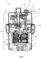
- the Figure 1 shows a first actuator 1 in a lateral sectional view.
- the actuator 1 comprises a engageable manual drive shaft 2 for manually driving the actuator 1.
- the manual drive shaft 2 can be engaged or coupled directly or indirectly with a gear of the actuator.
- the gear 5 in the example shown comprises an upper planetary gear 5A and a lower planetary gear 5B and is used, for example, to position a valve.
- Figure 1 shows the manual drive shaft 2 in a decoupled position, i.e. in a position in which the manual drive shaft 2 is not coupled to the gear 5.
- the actuator 1 comprises a housing 4.
- the housing 4 comprises a first, pot-shaped housing part 4A and a second housing part or housing cover 4B.
- a sealing element 11 or a sealing ring 11 is mounted between the first and second housing parts 4A, 4B.
- the sealing element 11 is, for example, a carrier of one or more sealing rings, such as O-rings.
- the first receptacle 7A is designed to receive the hand-held control element 3 or a part or a (coupling) end of the hand-held control element in order to connect the hand-held control element 3 to the housing 4, in particular to connect it in a force-fitting and/or form-fitting manner.
- the coupling element 7 further has a second receptacle 7B.
- the second receptacle 7B is directed inward, i.e., toward the interior of the actuator 1 or the housing 4.
- the second receptacle 7B is designed, for example, as a slip clutch or a tolerance sleeve.
- the second receptacle 7B is configured to receive the manual drive shaft 2 or a first end of the manual drive shaft 2.
- the manual control element 3 can be connected or coupled to the manual drive shaft 2 via the coupling element 7.
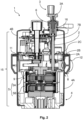
- FIG. 2 shows actuator 1 from Figure 1 in lateral sectional view. Identical or similar features are provided with the same reference symbols.
- Figure 2 shows the manual drive shaft 2 in a coupled or engaged position, i.e., in a position in which the manual drive shaft 2 is coupled to the gear 5.
- the manual drive shaft 2 has a coupling means 8.
- the coupling means 8 of the manual drive shaft 2 is coupled to a coupling means 9 of the gear 5, or is connected in a force-locking and/or form-locking manner.
- the coupling means 8 and 9 are, for example, intermeshing engagement means, such as gears.
- the coupling means 9 is mounted in the upper planetary gear 5A.
- the upper planetary gear 5A transmits a force introduced via the coupling means 9 to the lower planetary gear 5B.
- the hand drive shaft 2 By a translational movement of the hand drive shaft 2 along a longitudinal axis of the hand drive shaft 2, the hand drive shaft 2 can be moved from the decoupled position (as in Figure 1 shown) into the coupled position (as shown in Figure 2 shown) are moved, brought or forced.
- connecting the hand control element 3 to the housing 4 causes or forces the translational movement of the hand drive shaft 2 from the decoupled position into the coupled position.
- the hand control element 3 comprises, as shown in the Figures 1 and 2 shown a receiving element 6 for the positive and/or non-positive connection of the hand control element 3 with the Housing 4, more specifically with a correspondingly oppositely configured receiving element 16 of the housing 4.
- the hand control element 3 is rotatably arranged in the receiving element 6 of the hand control element 3.
- the receiving element 6 engages around the coupling end 3A of the hand control element 3.
- the hand control element 3 can be connected to the housing 4 via the receiving elements 6 and 16 by means of a bayonet lock.
- the receiving element 6 of the hand control element 3 can be rotatably engaged in the receiving element 16 of the housing 4.
- the actuator 1 further comprises a sensor and an element 2B detectable by the sensor in order to distinguish the engaged or coupled position of the manual drive shaft 2 from the disengaged or uncoupled position of the manual drive shaft 2.
- a movable coupling element or means for coupling the manual drive shaft 2 to the gear 5 can have the detectable element 2B.
- the movable coupling element with the detectable element 2B can, for example or alternatively, be the coupling element 7, the manual drive shaft 2 itself, or at least one of the coupling means 8 or 9.
- the sensor detects a translational movement of the detectable element 2B along the longitudinal axis of the manual drive shaft 2.
- the detectable element 2B can, for example, be a permanent magnet mounted next to or near a stationary magnetic field sensor, preferably enclosed by the housing 4 or a control electronics 2C.
- the actuator may comprise another type of detectable element 2B and/or sensor to distinguish the engaged position from the disengaged position.
- the receiving element 16 is separately in Figure 3 shown in three-dimensional view.
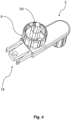
- the hand control element 3 is shown separately in Figure 4 in three-dimensional view Identical or similar features are provided with the same reference symbols.
- the Figure 5 shows a three-dimensional view of the actuator 1 from the Figures 1 and 2 . Identical or similar features are provided with the same reference symbols.
- the hand control element 3 is designed as a crank.
- the hand control element 3 can be fastened to the housing 4 on an outer wall, here the outer surface of the housing 4. In the fastened position of the hand control element 3 on the housing outer wall, the hand control element 3 is not connected to the housing 4 for coupling the manual drive shaft 2 to the gear 5.
- the fastened position of the hand control element 3 is different from the connected position of the hand control element 3 described above.
- the sealing ring 11 which is arranged between the two housing parts 4A and 4B of the housing, comprises a receptacle 13 for the hand control element 3 for fastening or mounting the hand control element 3 on the housing 4.
- the actuator 1 can be used as shown in Figure 5 shown, have a tensioning band 12.
- the tensioning band 12 comprises cable glands 17 for leading connecting cables into the interior of the housing 4.
- the housing 4 can have an opening that at least partially overlaps with openings of the cable glands 17.
- the tensioning band 12 can have a receptacle 13 for the hand-held control element 3.
- the hand control element 3 has engagement means 18 (see Fig. 4 ), which can engage in the receptacle 13 or be received by it. In this way, the hand control element 13 can be arranged on the housing 4 in a space-saving manner or can be attached to it when the hand control element 3 is not in use for manually driving the actuator 1.
- the engagement means 18 enclose an opening.
- the hand control element 3 can be attached to the opening for storage, for example on a key ring.
- the hand control element 3 can comprise a first magnetic element and/or ferromagnetic element that interacts with a second magnetic element and/or ferromagnetic element on the housing 4, the sealing ring 11 and/or the clamping band 12 in order to fasten the hand control element 3 to the housing 4.
- a cover 14, preferably fastened to the housing 4 can cover the coupling point 10, in particular the receiving element 16, of the housing 4 for the hand control element 3.
- the actuator 1 comprises a stack structure 15.
- the stack structure 15 comprises one or more functional units of the actuator 1.
- the functional units include, for example, a drive motor and/or one or more gears of the actuator 1.
- the actuator 1 comprises a connecting element.
- the connecting element is, for example, the sealing element 11 described above and/or is encompassed by it.
- Figure 6 shows a section of a cross-section of a second actuator 20 similar to that shown in the Figures 1 and 2 shown first actuator 1. Identical or similar features are provided with the same reference numerals.
- Figure 6 further shows a stack assembly element 19 as part of a stack assembly 15 arranged in the illustrated actuator.
- the stack assembly element 19 acts with a connecting element 21, which may comprise the sealing element 11 or may be comprised thereby, for connecting the stack structure 15 to the housing 4.
- the connecting element 21 may correspond to the sealing element 11 or be a second sealing element.
- the connecting element 21 and the stack structure element 19 are connected to one another laterally, ie, in a transverse direction to the stack structure and/or to the housing 4, in particular by means of force or frictional engagement.
- the stack structure 15 or the stack structure element 19 are spaced apart from the connecting element 21 in the longitudinal direction of the stack structure 15, wherein the stack structure element 19 and connecting element 21 are connected or contact each other in the transverse direction of the stack structure 15.
- the connection of the stack structure 15 to the housing 4 has an axial degree of freedom, here in the longitudinal direction of the stack structure 15.
- the connecting element 21 is designed to connect the housing 4 to a stack structure 15 of varying height. In this way, deviations in the extension of the stack structure 15 in the direction of the axial degree of freedom, or here in the longitudinal direction of the stack structure 15, which can occur during manufacture and/or operation of the stack structure, can be tolerated or taken into account.
Landscapes
- Engineering & Computer Science (AREA)
- General Engineering & Computer Science (AREA)
- Mechanical Engineering (AREA)
- Gear-Shifting Mechanisms (AREA)
- Transmission Devices (AREA)
Applications Claiming Priority (2)
| Application Number | Priority Date | Filing Date | Title |
|---|---|---|---|
| DE102021134550.2A DE102021134550A1 (de) | 2021-12-23 | 2021-12-23 | Stellantrieb |
| PCT/EP2022/077880 WO2023117169A1 (de) | 2021-12-23 | 2022-10-07 | Stellantrieb |
Publications (3)
| Publication Number | Publication Date |
|---|---|
| EP4453459A1 EP4453459A1 (de) | 2024-10-30 |
| EP4453459B1 true EP4453459B1 (de) | 2025-06-25 |
| EP4453459C0 EP4453459C0 (de) | 2025-06-25 |
Family
ID=84330313
Family Applications (1)
| Application Number | Title | Priority Date | Filing Date |
|---|---|---|---|
| EP22801386.8A Active EP4453459B1 (de) | 2021-12-23 | 2022-10-07 | Stellantrieb |
Country Status (8)
| Country | Link |
|---|---|
| US (1) | US20250060027A1 (pl) |
| EP (1) | EP4453459B1 (pl) |
| KR (1) | KR20240122440A (pl) |
| CN (1) | CN118414515A (pl) |
| DE (1) | DE102021134550A1 (pl) |
| ES (1) | ES3038452T3 (pl) |
| PL (1) | PL4453459T3 (pl) |
| WO (1) | WO2023117169A1 (pl) |
Families Citing this family (1)
| Publication number | Priority date | Publication date | Assignee | Title |
|---|---|---|---|---|
| USD1092265S1 (en) * | 2024-02-14 | 2025-09-09 | Auma Riester Gmbh & Co. Kg | Position indicator part of a valve actuator |
Family Cites Families (16)
| Publication number | Priority date | Publication date | Assignee | Title |
|---|---|---|---|---|
| US3863888A (en) | 1973-01-15 | 1975-02-04 | Paul D Hines | Power operated fluid control valve |
| DE2758443A1 (de) | 1977-12-28 | 1979-07-05 | Bbc Brown Boveri & Cie | Umschalteinrichtung fuer hand- oder motorbetrieb eines stellantriebs |
| US4647007A (en) * | 1986-02-24 | 1987-03-03 | Peter Bajka | Valve actuator with manual disengagement assembly |
| US4759386A (en) * | 1987-01-20 | 1988-07-26 | Pennwalt Corporation | Electromechanical linear actuator |
| US5295907A (en) * | 1990-05-04 | 1994-03-22 | Ava International Corporation | Rorque limiting device |
| DE4239947C1 (de) | 1992-11-27 | 1993-11-04 | Riester Kg Werner | Antriebseinheit zur steuerung und regelung von armaturen o. dgl. |
| JP3327086B2 (ja) * | 1995-12-22 | 2002-09-24 | 株式会社デンソー | 回転扉の駆動機構 |
| DE29807444U1 (de) * | 1998-04-24 | 1998-08-20 | Hartmann & Braun GmbH & Co. KG, 65760 Eschborn | Schalteinrichtung zum Handbetrieb eines elektromotorischen Stellantriebs |
| DE10322832B4 (de) * | 2003-05-19 | 2006-07-13 | Georg Fischer Rohrleitungssysteme Ag | Vorrichtung zur Handnotbetätigung von Ventilen |
| GB2404717B (en) * | 2003-07-17 | 2005-12-21 | Rotork Controls | Drive mechanisms for valve actuators |
| DE102009055741A1 (de) * | 2009-11-26 | 2011-06-09 | Bü-Sch Armaturen GmbH | Betätigungsvorrichtung für Gehäuse- oder gehäuselose Armaturen |
| ES2394267T3 (es) | 2010-02-11 | 2013-01-30 | Siemens Aktiengesellschaft | Accionamiento regulador de válvula con acoplamiento de sobrecarga |
| WO2016209940A1 (en) * | 2015-06-24 | 2016-12-29 | Cts Corporation | Rotary actuator |
| EP3150889A1 (en) * | 2015-10-01 | 2017-04-05 | IMI Hydronic Engineering International SA | An actuator for controlling a valve |
| CN211779270U (zh) * | 2019-12-27 | 2020-10-27 | 扬州市超能电动阀门有限公司 | 一种启闭机执行器 |
| CN112049977A (zh) * | 2020-09-12 | 2020-12-08 | 济南高瓴机械科技有限公司 | 一种电动球阀 |
-
2021
- 2021-12-23 DE DE102021134550.2A patent/DE102021134550A1/de active Pending
-
2022
- 2022-10-07 US US18/721,452 patent/US20250060027A1/en active Pending
- 2022-10-07 CN CN202280083121.XA patent/CN118414515A/zh active Pending
- 2022-10-07 EP EP22801386.8A patent/EP4453459B1/de active Active
- 2022-10-07 KR KR1020247018446A patent/KR20240122440A/ko active Pending
- 2022-10-07 ES ES22801386T patent/ES3038452T3/es active Active
- 2022-10-07 PL PL22801386.8T patent/PL4453459T3/pl unknown
- 2022-10-07 WO PCT/EP2022/077880 patent/WO2023117169A1/de not_active Ceased
Also Published As
| Publication number | Publication date |
|---|---|
| KR20240122440A (ko) | 2024-08-12 |
| ES3038452T3 (en) | 2025-10-13 |
| WO2023117169A1 (de) | 2023-06-29 |
| EP4453459C0 (de) | 2025-06-25 |
| CN118414515A (zh) | 2024-07-30 |
| DE102021134550A1 (de) | 2023-06-29 |
| PL4453459T3 (pl) | 2025-10-13 |
| EP4453459A1 (de) | 2024-10-30 |
| US20250060027A1 (en) | 2025-02-20 |
Similar Documents
| Publication | Publication Date | Title |
|---|---|---|
| EP3478992B1 (de) | Parksperreneinheit und elektroantriebsanordnung mit einer parksperre | |
| EP2531677B1 (de) | Verriegelungseinrichtung mit zuhaltung für schutztüren | |
| EP0666399B1 (de) | Antriebsvorrichtung für ein zwischen Endstellungen verstellbares Teil eines Fahrzeuges | |
| DE3118634C2 (de) | Verstellantrieb mit Schlingfederbremselement in einem Kraftfahrzeug, insbesondere für einen Fensterheber | |
| EP2342050B1 (de) | Handwerkzeugmaschine mit einem schaltbaren getriebe | |
| WO2016059095A1 (de) | Werkzeugwechselvorrichtung für manipulatoren | |
| DE102018112633B4 (de) | Fingereinheit für eine Roboterhand und Roboterhand | |
| EP4453459B1 (de) | Stellantrieb | |
| DE112019004638T5 (de) | Elektrischer Werkzeugwechsler | |
| EP0972665B1 (de) | Verschliessvorrichtung für ein Schliessbauteil eines Fahrzeugs | |
| EP4036355B1 (de) | Aktuierungsvorrichtung, schliesszylinder, schliesssystem und verfahren | |
| DE3619756A1 (de) | Sicherheitszylinderschloss | |
| DE102010033429A1 (de) | Industrieroboter | |
| EP3741934A1 (de) | Schliesszylinder | |
| DE19906268A1 (de) | Vorrichtung zur elektrischen Verriegelung der Lenkspindel einer Lenkeinrichtung | |
| DE10019132B4 (de) | Ratschen-Ringschlüssel für Überwurfmuttern an Leitungen | |
| DE102012224524B4 (de) | Kopplungsvorrichtung für eine Antriebsvorrichtung sowie Antriebseinrichtung | |
| EP1477714B1 (de) | Stellantrieb für Ventile | |
| DE3614096C2 (pl) | ||
| DE19927140A1 (de) | Kranunterflasche mit Drehantrieb | |
| CH707658A1 (de) | Drehstellantrieb. | |
| DE202005006571U1 (de) | Elektromotorischer Möbelantrieb | |
| DE202006006117U1 (de) | Rotations-Stellantrieb und Schnittstellenteil dafür | |
| DE102005055966A1 (de) | Blechgreif- oder Blechspannvorrichtung | |
| EP4198234A1 (de) | Spannvorrichtung |
Legal Events
| Date | Code | Title | Description |
|---|---|---|---|
| STAA | Information on the status of an ep patent application or granted ep patent |
Free format text: STATUS: UNKNOWN |
|
| STAA | Information on the status of an ep patent application or granted ep patent |
Free format text: STATUS: THE INTERNATIONAL PUBLICATION HAS BEEN MADE |
|
| PUAI | Public reference made under article 153(3) epc to a published international application that has entered the european phase |
Free format text: ORIGINAL CODE: 0009012 |
|
| STAA | Information on the status of an ep patent application or granted ep patent |
Free format text: STATUS: REQUEST FOR EXAMINATION WAS MADE |
|
| 17P | Request for examination filed |
Effective date: 20240621 |
|
| AK | Designated contracting states |
Kind code of ref document: A1 Designated state(s): AL AT BE BG CH CY CZ DE DK EE ES FI FR GB GR HR HU IE IS IT LI LT LU LV MC ME MK MT NL NO PL PT RO RS SE SI SK SM TR |
|
| GRAP | Despatch of communication of intention to grant a patent |
Free format text: ORIGINAL CODE: EPIDOSNIGR1 |
|
| STAA | Information on the status of an ep patent application or granted ep patent |
Free format text: STATUS: GRANT OF PATENT IS INTENDED |
|
| DAV | Request for validation of the european patent (deleted) | ||
| DAX | Request for extension of the european patent (deleted) | ||
| INTG | Intention to grant announced |
Effective date: 20250203 |
|
| GRAS | Grant fee paid |
Free format text: ORIGINAL CODE: EPIDOSNIGR3 |
|
| GRAA | (expected) grant |
Free format text: ORIGINAL CODE: 0009210 |
|
| STAA | Information on the status of an ep patent application or granted ep patent |
Free format text: STATUS: THE PATENT HAS BEEN GRANTED |
|
| AK | Designated contracting states |
Kind code of ref document: B1 Designated state(s): AL AT BE BG CH CY CZ DE DK EE ES FI FR GB GR HR HU IE IS IT LI LT LU LV MC ME MK MT NL NO PL PT RO RS SE SI SK SM TR |
|
| REG | Reference to a national code |
Ref country code: GB Ref legal event code: FG4D Free format text: NOT ENGLISH |
|
| REG | Reference to a national code |
Ref country code: CH Ref legal event code: EP |
|
| REG | Reference to a national code |
Ref country code: DE Ref legal event code: R096 Ref document number: 502022004440 Country of ref document: DE |
|
| REG | Reference to a national code |
Ref country code: CH Ref legal event code: EP |
|
| REG | Reference to a national code |
Ref country code: IE Ref legal event code: FG4D Free format text: LANGUAGE OF EP DOCUMENT: GERMAN |
|
| U01 | Request for unitary effect filed |
Effective date: 20250722 |
|
| U07 | Unitary effect registered |
Designated state(s): AT BE BG DE DK EE FI FR IT LT LU LV MT NL PT RO SE SI Effective date: 20250728 |
|
| PG25 | Lapsed in a contracting state [announced via postgrant information from national office to epo] |
Ref country code: NO Free format text: LAPSE BECAUSE OF FAILURE TO SUBMIT A TRANSLATION OF THE DESCRIPTION OR TO PAY THE FEE WITHIN THE PRESCRIBED TIME-LIMIT Effective date: 20250925 Ref country code: GR Free format text: LAPSE BECAUSE OF FAILURE TO SUBMIT A TRANSLATION OF THE DESCRIPTION OR TO PAY THE FEE WITHIN THE PRESCRIBED TIME-LIMIT Effective date: 20250926 |
|
| REG | Reference to a national code |
Ref country code: ES Ref legal event code: FG2A Ref document number: 3038452 Country of ref document: ES Kind code of ref document: T3 Effective date: 20251013 |
|
| PGFP | Annual fee paid to national office [announced via postgrant information from national office to epo] |
Ref country code: TR Payment date: 20250930 Year of fee payment: 4 |
|
| PG25 | Lapsed in a contracting state [announced via postgrant information from national office to epo] |
Ref country code: HR Free format text: LAPSE BECAUSE OF FAILURE TO SUBMIT A TRANSLATION OF THE DESCRIPTION OR TO PAY THE FEE WITHIN THE PRESCRIBED TIME-LIMIT Effective date: 20250625 |
|
| PG25 | Lapsed in a contracting state [announced via postgrant information from national office to epo] |
Ref country code: RS Free format text: LAPSE BECAUSE OF FAILURE TO SUBMIT A TRANSLATION OF THE DESCRIPTION OR TO PAY THE FEE WITHIN THE PRESCRIBED TIME-LIMIT Effective date: 20250925 |
|
| U20 | Renewal fee for the european patent with unitary effect paid |
Year of fee payment: 4 Effective date: 20251028 |