EP4445990A2 - Verfahren zur behandlung von abgasen aus pyrolytischer zersetzung eines polymers - Google Patents
Verfahren zur behandlung von abgasen aus pyrolytischer zersetzung eines polymers Download PDFInfo
- Publication number
- EP4445990A2 EP4445990A2 EP24185985.9A EP24185985A EP4445990A2 EP 4445990 A2 EP4445990 A2 EP 4445990A2 EP 24185985 A EP24185985 A EP 24185985A EP 4445990 A2 EP4445990 A2 EP 4445990A2
- Authority
- EP
- European Patent Office
- Prior art keywords
- enclosure
- fraction
- condensation
- monomer
- absorbent liquid
- Prior art date
- Legal status (The legal status is an assumption and is not a legal conclusion. Google has not performed a legal analysis and makes no representation as to the accuracy of the status listed.)
- Pending
Links
Images

Classifications
-
- B—PERFORMING OPERATIONS; TRANSPORTING
- B01—PHYSICAL OR CHEMICAL PROCESSES OR APPARATUS IN GENERAL
- B01D—SEPARATION
- B01D53/00—Separation of gases or vapours; Recovering vapours of volatile solvents from gases; Chemical or biological purification of waste gases, e.g. engine exhaust gases, smoke, fumes, flue gases, aerosols
- B01D53/14—Separation of gases or vapours; Recovering vapours of volatile solvents from gases; Chemical or biological purification of waste gases, e.g. engine exhaust gases, smoke, fumes, flue gases, aerosols by absorption
- B01D53/1418—Recovery of products
-
- B—PERFORMING OPERATIONS; TRANSPORTING
- B01—PHYSICAL OR CHEMICAL PROCESSES OR APPARATUS IN GENERAL
- B01D—SEPARATION
- B01D53/00—Separation of gases or vapours; Recovering vapours of volatile solvents from gases; Chemical or biological purification of waste gases, e.g. engine exhaust gases, smoke, fumes, flue gases, aerosols
- B01D53/14—Separation of gases or vapours; Recovering vapours of volatile solvents from gases; Chemical or biological purification of waste gases, e.g. engine exhaust gases, smoke, fumes, flue gases, aerosols by absorption
- B01D53/1412—Controlling the absorption process
-
- B—PERFORMING OPERATIONS; TRANSPORTING
- B01—PHYSICAL OR CHEMICAL PROCESSES OR APPARATUS IN GENERAL
- B01D—SEPARATION
- B01D53/00—Separation of gases or vapours; Recovering vapours of volatile solvents from gases; Chemical or biological purification of waste gases, e.g. engine exhaust gases, smoke, fumes, flue gases, aerosols
- B01D53/14—Separation of gases or vapours; Recovering vapours of volatile solvents from gases; Chemical or biological purification of waste gases, e.g. engine exhaust gases, smoke, fumes, flue gases, aerosols by absorption
- B01D53/1425—Regeneration of liquid absorbents
-
- B—PERFORMING OPERATIONS; TRANSPORTING
- B01—PHYSICAL OR CHEMICAL PROCESSES OR APPARATUS IN GENERAL
- B01D—SEPARATION
- B01D53/00—Separation of gases or vapours; Recovering vapours of volatile solvents from gases; Chemical or biological purification of waste gases, e.g. engine exhaust gases, smoke, fumes, flue gases, aerosols
- B01D53/14—Separation of gases or vapours; Recovering vapours of volatile solvents from gases; Chemical or biological purification of waste gases, e.g. engine exhaust gases, smoke, fumes, flue gases, aerosols by absorption
- B01D53/1431—Pretreatment by other processes
-
- B—PERFORMING OPERATIONS; TRANSPORTING
- B01—PHYSICAL OR CHEMICAL PROCESSES OR APPARATUS IN GENERAL
- B01D—SEPARATION
- B01D53/00—Separation of gases or vapours; Recovering vapours of volatile solvents from gases; Chemical or biological purification of waste gases, e.g. engine exhaust gases, smoke, fumes, flue gases, aerosols
- B01D53/14—Separation of gases or vapours; Recovering vapours of volatile solvents from gases; Chemical or biological purification of waste gases, e.g. engine exhaust gases, smoke, fumes, flue gases, aerosols by absorption
- B01D53/1487—Removing organic compounds
-
- B—PERFORMING OPERATIONS; TRANSPORTING
- B01—PHYSICAL OR CHEMICAL PROCESSES OR APPARATUS IN GENERAL
- B01D—SEPARATION
- B01D53/00—Separation of gases or vapours; Recovering vapours of volatile solvents from gases; Chemical or biological purification of waste gases, e.g. engine exhaust gases, smoke, fumes, flue gases, aerosols
- B01D53/14—Separation of gases or vapours; Recovering vapours of volatile solvents from gases; Chemical or biological purification of waste gases, e.g. engine exhaust gases, smoke, fumes, flue gases, aerosols by absorption
- B01D53/1493—Selection of liquid materials for use as absorbents
-
- B—PERFORMING OPERATIONS; TRANSPORTING
- B01—PHYSICAL OR CHEMICAL PROCESSES OR APPARATUS IN GENERAL
- B01D—SEPARATION
- B01D53/00—Separation of gases or vapours; Recovering vapours of volatile solvents from gases; Chemical or biological purification of waste gases, e.g. engine exhaust gases, smoke, fumes, flue gases, aerosols
- B01D53/34—Chemical or biological purification of waste gases
- B01D53/46—Removing components of defined structure
- B01D53/72—Organic compounds not provided for in groups B01D53/48 - B01D53/70, e.g. hydrocarbons
-
- B—PERFORMING OPERATIONS; TRANSPORTING
- B01—PHYSICAL OR CHEMICAL PROCESSES OR APPARATUS IN GENERAL
- B01D—SEPARATION
- B01D2252/00—Absorbents, i.e. solvents and liquid materials for gas absorption
- B01D2252/20—Organic absorbents
- B01D2252/202—Alcohols or their derivatives
-
- B—PERFORMING OPERATIONS; TRANSPORTING
- B01—PHYSICAL OR CHEMICAL PROCESSES OR APPARATUS IN GENERAL
- B01D—SEPARATION
- B01D2252/00—Absorbents, i.e. solvents and liquid materials for gas absorption
- B01D2252/20—Organic absorbents
- B01D2252/202—Alcohols or their derivatives
- B01D2252/2021—Methanol
-
- B—PERFORMING OPERATIONS; TRANSPORTING
- B01—PHYSICAL OR CHEMICAL PROCESSES OR APPARATUS IN GENERAL
- B01D—SEPARATION
- B01D2252/00—Absorbents, i.e. solvents and liquid materials for gas absorption
- B01D2252/20—Organic absorbents
- B01D2252/205—Other organic compounds not covered by B01D2252/00 - B01D2252/20494
-
- B—PERFORMING OPERATIONS; TRANSPORTING
- B01—PHYSICAL OR CHEMICAL PROCESSES OR APPARATUS IN GENERAL
- B01D—SEPARATION
- B01D2256/00—Main component in the product gas stream after treatment
- B01D2256/24—Hydrocarbons
-
- B—PERFORMING OPERATIONS; TRANSPORTING
- B01—PHYSICAL OR CHEMICAL PROCESSES OR APPARATUS IN GENERAL
- B01D—SEPARATION
- B01D2257/00—Components to be removed
- B01D2257/70—Organic compounds not provided for in groups B01D2257/00 - B01D2257/602
- B01D2257/702—Hydrocarbons
-
- C—CHEMISTRY; METALLURGY
- C10—PETROLEUM, GAS OR COKE INDUSTRIES; TECHNICAL GASES CONTAINING CARBON MONOXIDE; FUELS; LUBRICANTS; PEAT
- C10B—DESTRUCTIVE DISTILLATION OF CARBONACEOUS MATERIALS FOR PRODUCTION OF GAS, COKE, TAR, OR SIMILAR MATERIALS
- C10B53/00—Destructive distillation, specially adapted for particular solid raw materials or solid raw materials in special form
- C10B53/07—Destructive distillation, specially adapted for particular solid raw materials or solid raw materials in special form of solid raw materials consisting of synthetic polymeric materials, e.g. tyres
Definitions
- the present invention relates to the field of treatment of gaseous effluents resulting from the decomposition of polymer(s).
- the invention relates to a method for treating a gas resulting from a pyrolytic decomposition of a polymer or a mixture of polymers.
- This method finds its application in the recycling of plastics and plastic residues generally comprising several polymers of different grades and in particular in the recycling of polymer compounds comprising a single family of polymers.
- Thermal pyrolysis involves placing the plastic object to be treated in a suitable chamber and then heating the chamber so that the heat is transferred to the object. It is used to treat plastic waste and generally results in carbonaceous residues, oil and gases that cannot be reused as such for the production of thermoplastic polymer matrix.
- thermal decomposition processes are used in particular to decompose PMMA (polymethyl methacrylate), polystyrene or other plastic residues.
- PMMA polymethyl methacrylate
- polystyrene polystyrene
- thermal decomposition of residues plastics it is possible to recover a mixture of products, usable as fuel or fuel oil.
- the core fraction of the pyrolysis of polyolefins is for example rich in a naphtha-type cut (pyrolysis gasoline), which can advantageously be used to feed a steam cracker (classic petrochemical unit) in order to produce olefins again.
- a steam cracker classic petrochemical unit
- the gaseous effluents resulting from this thermal decomposition by pyrolysis of polymer(s) are rich in compound(s) that we wish to recover and recycle.
- the gaseous effluent must be condensed.
- a heat exchanger is classically used in which the gaseous effluent will circulate, so that the heat exchanger cools the gaseous effluent until a liquid fraction is produced.
- the product recovered from this condensation is of relatively poor quality and requires subsequent washing steps and then purification by distillation.
- the gaseous effluent resulting from the thermal decomposition of the polymer(s) is composed of light, medium and heavy molar fractions.
- the monomer(s) that we seek to recover and valorize are essentially present in the medium molar fraction. The applicant therefore sought a solution that would allow this molar fraction of interest to be isolated more effectively.
- the document WO 2017/179009 describes a process and system for separating C3 hydrocarbons from a gas mixture.
- the separation of the components in this system is according to their boiling point, so the process and system correspond to a distillation column.
- the document US 2016/145185 describes a process for recovering purified (meth)acrylic acid during the synthesis of (meth)acrylic acid.
- the document describes a step of purifying a compound during its synthesis process and heating the distillation columns.
- the invention therefore aims to remedy at least one of the aforementioned drawbacks of the prior art.
- the invention aims in particular to propose a simple and effective solution for isolating a molar fraction of interest from a gaseous effluent resulting from the thermal decomposition of a polymer or a mixture of polymer(s), in order to recover one or more compound(s) (e.g. monomer(s)) of improved quality.
- condensation by means of an absorption device allowing the gaseous effluent to be brought into contact with an absorbent liquid whose temperature is much lower than that of the effluent, followed by the partial vaporization of the condensate obtained in the presence in particular of a pressure differential, makes it possible to effectively isolate the monomer(s) contained in the gaseous effluent resulting from the decomposition of one or more polymers.
- the term “monomer” is understood to mean a molecule that can undergo polymerization.
- the term “monomer” is understood to mean the most important monomer unit constituting a polymer.
- the monomer is Methyl MethAcrylate (MMA) while it is styrene for polystyrene.
- polymerization refers to the process of transforming a monomer or mixture of monomers into a polymer.
- depolymerization refers to the process of transforming a polymer into one or more monomer(s) and/or oligomer(s) and/or polymer(s) of lower molar mass than the initial polymer.
- pyrolytic decomposition corresponds, in the sense of the invention, to a step of rising to very high temperature leading to a transformation of a polymer into different compounds including monomers.
- thermoplastic polymer means a polymer that can be repeatedly softened or melted under the action of heat and that adopts new shapes by the application of heat and pressure.
- thermoplastics are, for example: polyethylene, a (meth)acrylic polymer such as poly(methyl methacrylate) (PMMA), or polystyrene (PS), polyLactic acid (PLA), polyhydroxyalkanoates (PHA).
- PMMA Poly(methyl methacrylate)
- PMMA is a particular example of a (methacrylic) polymer obtained by polymerization of a methyl methacrylate monomer.
- PMMA for the purposes of the invention denotes homo- and copolymers of methyl methacrylate (MMA), the weight ratio of MMA in PMMA preferably being at least 70% by weight for the MMA copolymer.
- methyl methacrylate-based copolymer means a copolymer having at least one methyl methacrylate monomer.
- a methyl methacrylate-based copolymer may be a copolymer comprising at least 70%, preferably 80%, advantageously 90% by weight of MAM in the PMMA.
- Light mole fraction means the proportion of a component whose relative volatility, compared to the other components of a mixture, is the highest; "medium mole fraction” means the proportion of a component whose relative volatility, compared to the other components of the mixture, is medium; and “heavy mole fraction” means the proportion of a component whose relative volatility, compared to the other components of the mixture, is the lowest.
- standard state molar specific heat expressed in J.mol -1 .K -1 , means the quantity of heat required to supply one mole of a compound to raise its temperature by 1°C.
- Condensation means the change of state of a compound from a gaseous to a liquid state.
- Vaporization means the change of state of a compound from a liquid to a gaseous state.
- the term "condensate” means a mixture of compounds obtained at the end of a gas condensation step.
- this mixture preferably comprises one or more monomer(s) and an absorbent liquid having participated, in particular by heat exchange, in the condensation of the monomer(s).
- the condensate may also correspond to one or more monomer(s) after a purification step.
- the gas to be condensed comprises at least 30% by mass, preferably at least 40% by mass and more preferably at least 50% by mass of the condensable materials.
- the expression “absorbent liquid” corresponds to a compound, in the liquid state at a temperature of 50°C and a pressure of 1 bar absolute, being capable of absorbing thermal energy originating from the monomer(s) of the gaseous effluent.
- Gas effluent means a reaction product resulting from thermal decomposition and comprising molar fractions which may include in particular the monomer(s).
- the gas to be condensed comprises at least 30% by mass, preferably at least 40% by mass and more preferably at least 50% by mass of condensable materials.
- heat exchange is meant, within the meaning of the invention, a system for transferring heat between a first element and a second element, the first element having a higher temperature than the second element, this causing the first element to cool and the second to heat up.
- bringing into contact is meant, within the meaning of the invention, direct contact, i.e. a heat exchange without a separation wall between the first and second elements.
- fluid communication within the meaning of the invention corresponds to the fact that two parts are arranged so as to allow the passage of a fluid from a first part to a second part without there being any leakage.
- substantially equal means a value varying by less than 30% relative to the compared value, preferably by less than 20%, even more preferably by less than 10%.
- the invention relates to a method 200 for treating a gaseous effluent.
- the gaseous effluent generally originates from the pyrolytic decomposition of a polymer or a mixture of polymers.
- the polymer can for example be polyethylenes such as high density polyethylene (HDPE) or polyethylene terephthalate (PET); polypropylene, polybutadiene and polybutylene, a homo- and copolymer of olefins such as acrylonitrile-butadiene-styrene copolymers, styrene-butadiene-alkyl methacrylate (or SBM) copolymers; acrylic homo- and copolymers and polyalkyl methacrylates such as poly(methyl methacrylate) (PMMA); a polyhydroxyalkanoate; homo- and copolyamides; polycarbonates; polyesters including poly(ethylene terephthalate) and poly(butylene terephthalate); polyethers
- a PolyHydroxyAlkanoate may for example be selected from: poly-3-hydroxybutyrate (P3HB), poly-4-hydroxybutyrate (P4HB), poly-3-hydroxypropionate (P3HP), poly-5-hydroxyvalerate (P5HV), poly-6-hydroxyhexanoate, polylactic acid (PLA), polyglycolic acid, poly-3-hydroxybutyrate-co-3-hydroxypropionate, poly-3-hydroxybutyrate-co-(D)-lactide, poly-3-hydroxybutyrate-co-4-hydroxybutyrate (poly-3HB-co-4HB), poly-3-hydroxybutyrate-co-3-hydroxyvalerate (poly-3-HB-co-3HV), poly-3-hydroxybutyrate-co-5-hydroxyvalerate and poly-3-hydroxybutyrate-co-3-hydroxyhexanoate which are essentially polyesters produced naturally by microorganisms and which are formed by the polymerization of one or more monomers.
- Monomeric components of PHAs include, but are not limited to, acid or ester forms such as acrylic acid, 3-hydroxybutyric acid, 3-hydroxybutyrate, 3-hydroxypropionate, 3-hydroxyvalerate, 3-hydroxyhexanoate, 3-hydroxyheptanoate, 3-hydroxyoctanoate, 3-hydroxynonanoate, 3-hydroxydecanoate, 3-hydroxydodecanoate, 4-hydroxybutyrate, 4-hydroxyvalerate, 5-hydroxyvalerate, 6-hydroxyhexanoate, 2-Methyl-3-hydroxypropanoate, 2-Methyl-2-hydroxypropanoate, 2-hydroxypropanoate (lactic acid), and 2-hydroxyethanoate (glycolic acid); and/or lactone or lactam forms such as caprolactone or caprolactam, or propiolactone, butyrolactone, valerolactone.
- acid or ester forms such as acrylic acid, 3-hydroxybutyric acid, 3-hydroxybutyrate, 3-hydroxypropionate, 3-hydroxyvalerate, 3-hydroxy
- Such monomeric components may form homopolymers or copolymers.
- PHA copolymers having two different monomer components have been provided, PHA may have more than two different monomer components.
- PHA and PLA Upon pyrolysis of PHA and PLA, other monomer components may be formed and used as monomers, or as reactants in further syntheses.
- the polymer is selected from: Polymethyl Methacrylate (PMMA), a polyhydroxyalkanoate, PLA, polystyrene, copolymers of styrene and anhydride, or a mixture of two or more of these polymers.
- PMMA Polymethyl Methacrylate
- PLA Polymethyl Methacrylate
- PLA polyhydroxyalkanoate
- PLA polystyrene
- copolymers of styrene and anhydride or a mixture of two or more of these polymers.
- the polymer may be derived from a composite material comprising a polymer and a reinforcement.
- the product of interest may be a monomer or a mixture of monomers resulting from the decomposition of the polymer(s).
- the product of interest may in particular be a monomer or a mixture of monomers resulting from the decomposition of the polymer(s).
- the user will have a fraction enriched in monomers which he can, for example, use as is, purify further or even transform.
- the monomer(s) may for example be selected from the following compounds: methyl methacrylate, methyl acrylate, ethyl acrylate, acrylic acid, methacrylic acid, styrene, crotonic acid, gamma-butyrolactone, delta-valerolactone and mixtures thereof.
- the monomer(s) are selected from the following compounds: methyl methacrylate, methacrylic acid, acrylic acid, styrene, and mixtures thereof.
- the gas to be treated comes from the thermal decomposition of a thermoplastic polymer and the product of interest to be recovered is the monomer of the decomposed polymer.
- the monomer thus recovered can then be recycled.
- the process uses an absorbent liquid which can advantageously be reused within the framework of a cyclic condensation system which will be detailed later.
- the absorbent liquid is advantageously selected to best promote heat exchanges with the gaseous effluent in the condensation enclosure 110 on the one hand and partial vaporization of the condensate during expansion in the second enclosure 130 on the other hand.
- the choice of the absorbent liquid is preferably adapted to the monomer(s) to be recovered.
- the monomer(s) to be recovered are liquid at atmospheric pressure of 1013 mbar.
- the absorbent liquid is selected so that the ratio between its latent heat of vaporization ⁇ Hv in the standard state and its molar specific heat Cp in the standard state is as high as possible and, in any case, greater than that of the monomer(s) to be recovered.
- the efficiency of the treatment method according to the invention is greatly improved.
- the latent heat of vaporization ⁇ Hv in the standard state of the absorbent liquid is for example greater than or equal to 20 kJ/mole, preferably greater than or equal to 30 kJ/mole, more preferably greater than or equal to 40 kJ/mole, and even more preferably greater than or equal to 50 kJ/mole.
- the absorbent liquid is chosen from one of the following compounds: benzene, benzonitrile, a compound of formula R-OH, a compound of formula R-COOH, in which R can be chosen from alkyls, the number of carbons of which is between 1 and 5, a phenyl or a hydrogen.
- the absorbent liquid may for example be selected from: benzene (71-43-2), benzonitrile (100-47-0), dihydrogen monoxide (7732-18-5), methanol (67-56-1), ethanol (64-17-5), propanol (71-23-8 or 67-63-0), butanol (71-36-3; 78-92-2; 15892-23-6; 14898-79-4; 4221-99-2), phenol (108-95-2), formic acid (64-18-6), acetic acid (64-19-7) or mixtures thereof.
- the absorbent liquid is chosen from one of the following compounds: a compound of formula R-OH, a compound of formula R-COOH, in which R can be chosen from alkyls, the number of carbons of which is between 1 and 5, or a hydrogen.
- the absorbent liquid may for example be selected from: dihydrogen monoxide (7732-18-5), methanol (67-56-1), ethanol (64-17-5), propanol (71-23-8 or 67-63-0), butanol (71-36-3; 78-92-2; 15892-23-6; 14898-79-4; 4221-99-2), formic acid (64-18-6), acetic acid (64-19-7) or mixtures thereof.
- the absorbent liquid is chosen so that its boiling point is of the order of magnitude of that of the monomer(s) to be recovered, i.e. it is not more than 80°C lower or higher, preferably 50°C, than the boiling point of the monomer(s) to be recovered. In this case, the formation of azeotropes between the absorbent liquid and the monomer(s) cannot be excluded.
- the absorbent liquid preferably has a boiling point higher than or substantially equal to that of the monomer(s) to be recovered and/or of the azeotrope that it forms with the monomer(s) to be recovered.
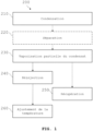
- the method according to the invention comprises a condensation step 210 including the injection of the gaseous effluent into a condensation enclosure 110 maintained under a first pressure p 1 .
- the condensation enclosure 110 can for example be maintained at a pressure p 1 of between 0.1 and 5 bars, preferably between 0.5 and 2 bars and preferably between 0.8 and 1.5 bars and more preferably between 0.9 and 1.2 bars absolute.
- the condensation step 210 also comprises bringing the gaseous effluent into contact with an absorbent liquid.
- the temperature of the absorbent liquid is lower than the temperature of the gaseous effluent, so that said monomer(s) condense(s) upon contact with the absorbent liquid.
- the temperature of the liquid absorbent is at least 50°C lower than the temperature of the gaseous effluent, more preferably at least 60°C lower and even more preferably at least 80°C lower.
- the temperature of the absorbent liquid is for example at most 450°C lower than the temperature of the gaseous effluent.
- the temperature of the absorbent liquid is at least 50°C and at most 450°C lower than the temperature of the gaseous effluent, and more advantageously at least 60°C and at most 450°C.
- the absorbent liquid may have, at its inlet into the condensation enclosure 110, a temperature of less than or equal to 140°C, preferably less than or equal to 120°C, more preferably less than or equal to 100°C and even more preferably less than or equal to 80°C.
- the contacting can for example be carried out via a spray column (aspersion), a micro-aspersion, a bubble column, a packed column, a falling film, a plate column, a venturi effect (for example BUSS-LOOP type systems), a centrifugal contact system of the spinning disk type or of the "rotating packed bed - RPB" type also known as HiGee.
- a spray column for example, a micro-aspersion, a bubble column, a packed column, a falling film, a plate column, a venturi effect
- BUSS-LOOP type systems for example BUSS-LOOP type systems
- additives may be added to the absorbent liquid during the condensation step 210.
- polymerization-inhibiting additives such as hydroquinone, phenothiazine (PTZ), monomethyl ether hydroquinone (MEHQ) or other known products limiting radical polymerization reactions, which makes it possible to stabilize the gaseous effluent, once condensed, resulting from the pyrolysis of polymer(s).
- the method according to the invention can also include a step of controlling the acid-base content of the absorbent liquid and regulating its pH by adjusting the flow rate of an acid or basic solution so that the pH is between 4 and 9, preferably between 5 and 8.
- This pH control is particularly important when the pyrolysis reaction generates basic or acidic by-products that could accumulate in the absorbent liquid and cause corrosion of the installations.
- pH control makes it possible to eliminate acids formed during pyrolysis or to separate these acids from the other components according to their acidity constant.
- the method according to the invention can comprise a step of injecting into the absorbent liquid a base such as a base selected from calcium oxide, sodium hydroxide, calcium hydroxide or potassium hydroxide, sodium or potassium methylate, sodium, potassium or calcium hydrogen carbonates or carbonates.
- a base such as a base selected from calcium oxide, sodium hydroxide, calcium hydroxide or potassium hydroxide, sodium or potassium methylate, sodium, potassium or calcium hydrogen carbonates or carbonates.
- a light molar fraction possibly contained in the gaseous effluent resulting from the pyrolysis of polymer(s) may not be completely condensed by contact with the absorbent liquid. It can then be evacuated from the condensation enclosure 110, in the gaseous state, via the outlet orifice 113 arranged at the upper end of the condensation enclosure 110.
- the method according to the invention can also comprise a step of recovering a non-condensed light molar fraction and bringing it into contact with a heat exchanger. Indeed, this light fraction can be recovered energetically to allow for example the depolymerization of plastic residues.
- the method according to the invention may comprise a separation step 220 downstream of the condensation step 210.
- This separation step 220 may be intended to purify the condensate generated during the condensation step 210 before the partial vaporization step 230.
- This separation step 220 may for example comprise filtration, decantation or even centrifugation.
- the temperature of the condensate can be modified via an additional heat exchanger not shown in the Figure 1 .
- the method may further comprise a step of heating the condensate obtained at the end of the condensation step 210 before the partial vaporization step 230.
- the method according to the invention also comprises a step of partial vaporization 230 of the condensate obtained at the end of the condensation step 210.
- This partial vaporization is permitted by implementing an expansion of the condensate in a second enclosure 130 maintained at a pressure p 2 lower than the pressure p 1 of the first condensation enclosure 110.
- the second enclosure 130 can for example be maintained at a pressure p 2 of between 0.001 and 0.8 bars, preferably between 0.01 and 0.5 and more preferably between 0.1 and 0.4 bars, limits included.
- the pressure difference ⁇ p 1 -p 2 in absolute value between the first enclosure 110 and the second enclosure 130 is greater than or equal to 0.5 bar, preferably greater than or equal to 0.6 bar, more preferably greater than or equal to 0.7 bar and even more preferably greater than or equal to 0.8 bar.
- a temperature difference between the first enclosure 110 and the second enclosure 130 can be achieved by adjusting the pressure difference ⁇ p 1 -p 2 between these two enclosures.
- the temperature difference between the first enclosure 110 and the second enclosure 130 is substantially equal to 25°C.
- the temperature difference will advantageously be at least equal to 5°C and less than or equal to 25°C. Such values make it possible to improve the performance of the treatment method.
- additives can be added to the circuit at the time of the partial vaporization step 230.
- the additives are here also preferably polymerization inhibitors.
- the method according to the invention also comprises a recovery step 250 comprising a purification of a second fraction. loaded with monomer(s), liquid or vapor, obtained at the end of the partial vaporization step 230.
- the recovery step 250 preferably comprises a condensation of the vapor fraction obtained at the end of the partial vaporization step 230.
- the recovery step 250 may comprise a filtration or decantation of the liquid fraction obtained at the end of the partial vaporization step 230. Said condensation of the vapor fraction, as well as said filtration or decantation of the liquid fraction obtained at the end of the partial vaporization step 230 are considered as purifications in the recovery step 250.
- the method according to the invention comprises an additional separation step.
- the constituent products of the azeotrope i.e. in the present case the absorbent liquid and the monomer(s)
- the absorbent liquid may be used again during the condensation step 210.
- This separation will consist, for example, in using two successive distillation columns maintained at different pressures, and/or liquid-liquid extractions or even extractive distillations.
- This additional step advantageously makes it possible to isolate the monomer(s) that it is desired to recover and to recycle the absorbent liquid in order to return it to the condensation loop.
- the recovery step may also include an injection of polymerization inhibitors so as to maintain a content of the order of 5 to 300 mg/kg in the monomer solution.
- the method according to the invention also comprises a reinjection step 240 consisting of redirecting, at least in part, a first fraction, liquid or vapor, obtained at the end of the partial vaporization step 230 towards the condensation enclosure 110.
- This first fraction preferably comprises a majority of liquid absorbent, in liquid or gaseous form following the partial vaporization step 230.
- the reinjection step 240 preferably comprises a condensation of this vapor fraction obtained at the end of the partial vaporization step 230.
- the reinjection step 240 comprises the redirection, towards the condensation enclosure 110, of at least a portion of the liquid fraction obtained at the end of the partial vaporization step 230.
- the first fraction in the form of a liquid fraction, can undergo a separation step making it possible to return a fraction enriched in absorbent liquid.
- the fraction thus redirected can be used to reabsorb the monomer(s) contained in the gaseous effluent.
- the method according to the invention may further comprise a step of adjusting the temperature 260 of the fraction redirected towards the condensation enclosure 110.
- this fraction a priori liquid, may be reheated or cooled before being reintroduced into the condensation enclosure 110.
- the absorbent liquid may be contaminated by residues resulting in particular from pyrolytic decomposition of the polymer or the polymer mixture.
- the absorbent liquid may be subject to a purification step that may be implemented by a purification device 150 or 170.
- This purification step may for example correspond to filtration, decantation, centrifugation, distillation, membrane separation, solvent extraction and/or condensation and any possible combination.
- the method according to the invention therefore comprises a step of injecting absorbent liquid into the system at a point injection point 116.
- the injected absorbent liquid is at a temperature low enough for the increase in temperature of the absorbent liquid to absorb the heat of condensation of the monomer(s) without causing significant vaporization of the absorbent liquid.
- the injection point 116 may also allow the injection of additives and in particular polymerization inhibitors with the fresh absorbent liquid.
- the method comprises a step of injecting polymerization inhibitors so as to maintain a content of the order of 5 to 300 mg/kg of monomer(s) in the absorbent liquid, and preferably of 50 to 200 mg/kg of monomer(s).
- the method according to the invention may comprise a step of analyzing the absorbent liquid.
- This analysis step may, for example, comprise a measurement of the pH, conductivity, and/or density. It may also comprise carrying out an analysis by gas chromatography or establishing an infrared or Raman spectrum.
- the invention relates to a processing system.
- the following description of the system according to the invention is made with reference to the Figure 2 which represents a diagram of the system according to one embodiment.
- the invention is not limited to this diagram, and the system can be produced in different possible variants without departing from the scope of the invention.
- the system 100 makes it possible to treat gaseous effluents resulting from a pyrolytic decomposition of a polymer or a mixture of polymers, in order to be able to recover a product of interest contained in these gaseous effluents.
- the system 100 comprises a first enclosure, also called a condensation enclosure or condensation stage hereinafter and referenced 110.
- this condensation enclosure 110 which can be placed under a first pressure p 1 , comprises an inlet orifice 111.
- the still hot gaseous effluent resulting from the thermal decomposition of the polymer(s) arrives via this orifice 111 for entry into the condensation enclosure 110.
- the condensation enclosure 110 is further equipped with an absorption device 112. This absorption device 112 makes it possible to inject an absorbent liquid into the enclosure and therefore to allow contact between this absorbent liquid and the incoming gaseous effluent.
- the absorption device 112 may be a liquid dispersion device as illustrated in the figure 2 but also consist of a packed column, a dispersion system and liquid-gas contact...
- the temperature of the absorbing liquid is much lower than that of the gaseous effluent, so that the monomer(s) contained in the gaseous effluent can condense in the absorbing liquid by heat exchange.
- the absorption device 112 could correspond to a device for spraying the absorbent liquid located above the inlet orifice of the gaseous effluent and capable of capturing the gaseous effluent.
- a mist can form because of the fine droplets of absorbent. This mist can then be carried along with the non-condensable gases and lead to a loss of absorbent and product.
- the installation is then equipped with a mist capture system (liquid/gas coalescer), which generally consists of a packing, or a fine mesh which causes the coalescence of the droplets. This type of installation is well known to those skilled in the art.
- the condensation enclosure 110 may also comprise an outlet orifice 113 capable of allowing the evacuation of a possible light molar fraction, contained in the gaseous effluent resulting from the pyrolysis of polymer(s), which would not be condensed by contact with the absorbent liquid.
- This light molar fraction may for example be the subject of a downstream treatment which may in particular include condensation.
- the liquid mixture condensed at a first pressure p 1 containing in particular the monomer(s) and the absorbent liquid, also called condensate in the remainder of the description, can be evacuated via an outlet orifice 114 preferably arranged in the bottom of the condensation enclosure 110.
- the condensate when in the form of a two-phase system, it is possible to further provide a device 120 for separating the compounds by filtration, decantation or centrifugation for example.
- a first phase of absorbent liquid essentially free of the monomer(s) having condensed, is reinjected, by means of a pump, into the condensation stage 110 via the absorption system 112, just after the separation means 120, according to the circuit in dotted lines on the diagram of the Figure 2 , while the other phase of absorbent liquid containing the compounds that have condensed is conveyed to the second enclosure 130.
- This separation means then makes it possible to carry out a first purification of the condensate.
- the separation means 120 is preferably arranged upstream of the second enclosure 130.
- the absorbent liquid separated by decantation can be purified for example by isothermal adsorption, the impurities contained in the absorbent liquid being for example trapped on activated carbons, zeolite, ion exchange resins, or any other adsorption technique.
- the absorbent liquid is then subsequently recombined with the other phase of absorbent liquid resulting from the decantation and directed towards the unit 130.
- the separation device 120 illustrated in the figure 2 may also be a condensate filtration device for removing dust from pyrolysis.
- the separation device 120 may advantageously be selected from: a filter such as a filter press, an activated carbon filter, a decanter or a centrifuge.
- the separation device 120 may in some cases be combined with an esterification reaction in order to improve the purification of the condensate.
- the absorbent liquid is selected from alcohols or contains significant quantities of alcohols, as well as organic acids
- acid resins such as Amberlyst® (eg Amberlyst A15, 35, 16, 36, 39, 46, 70, 131), catalysts supported enzymatic, and other solid acid catalysts.
- esterification reaction of organic acids is favored by equilibrium shift, and water is produced stoichiometrically to the amount of acid converted. Esterification reactions are generally not very endothermic or exothermic. The temperature of the condensate is thus maintained.
- the system 100 comprises a second enclosure 130 to which the condensate, whether or not it has been the subject of prior separation, can then be conveyed.
- This second enclosure 130 is capable of being maintained at a second pressure p 2 lower than the first pressure p 1 .
- the condensate arriving in this second enclosure 130 is then expanded, which causes partial adiabatic vaporization of the condensate.
- the second enclosure 130 for relaxing the condensate and causing partial adiabatic vaporization of the condensate may be in the form, for example, of a thin-film evaporator, such as the evaporator marketed by UIC GmBh, or by VTA Maschinenstechnische Anlagen GmbH & Co, either as a scraped-film evaporator or as a short-travel-time evaporator, or in the form of a vortex-effect cylinder into which the condensate is injected tangentially to the wall to cause rotation of the fluid and a vortex effect which creates a depression in its center, the product then being drawn off at the bottom (marketed by Penn Separator).
- the second enclosure 130 has at least two outlet orifices, a first orifice for evacuating the vapor fraction resulting from the partial vaporization and a second orifice for evacuating the non-evaporated liquid fraction.
- the monomer(s), preferably the monomer(s), resulting from the decomposition of the polymer(s) will be contained mainly in the vapor fraction or in the liquid fraction. Indeed, if the absorbent liquid is chosen so that its boiling point is significantly higher than that of the monomer(s) to be recovered, then it is likely that the monomer(s) resulting from the decomposition of the polymer(s) will be contained mainly in the vapor fraction.
- the vapor fraction comprises an average molar fraction of the gaseous effluent, the light molar fraction having already been evacuated at the condensation enclosure and the heavy molar fraction remaining absorbed in the absorbent liquid.
- the vapor fraction comprises the monomer(s), preferably basic, resulting from the decomposition of the polymer(s).
- This vapor fraction can then be conveyed to a heat exchanger 131 in order to be condensed, then to a purification device 150, such as a distillation column for example, in order to be purified.
- This monomer-rich fraction can then be recovered.
- the liquid fraction comprises a majority of absorbent liquid
- the condensation enclosure 110 where it will again absorb the base monomer(s) by heat exchange.
- the absorbent liquid therefore circulates in a loop in the system 100.
- a pump 140 arranged downstream of the outlet of the second enclosure 130, makes it possible to recover this liquid fraction and to convey it towards the condensation stage.
- the system 100 can also be called a “condensation loop”.
- the system advantageously comprises a purification device 170 capable of purifying, by example regularly, a part of the fraction comprising a majority of the absorbent liquid from the second enclosure 130 after the expansion of the condensate.
- the fraction comprising a majority of the absorbent liquid is the liquid fraction as illustrated in the figure 2 .
- the purification device 170 may for example be selected from: a distillation unit, a membrane, a decanter, an extraction means, an adsorption unit, an ion exchange resin.
- the purification device 170 makes it possible to rid the absorbent liquid of impurities accumulated as the absorbent liquid passes through the condensation enclosure 110 in a loop.
- the system 100 may comprise a device 180 for analyzing the absorbent liquid. Indeed, it is appropriate to check whether the absorbent liquid that is going to be reinjected meets predetermined quality criteria.
- the analysis device may for example be selected from: infrared spectrometer, Raman analysis, a gas chromatography system, a conductivity meter, a thermometer or a pH meter.
- the system may advantageously comprise a purge point 115 capable of removing, preferably regularly, absorbent liquid and an injection point 116 capable of reinjecting, preferably regularly, absorbent liquid so that the method can be implemented with an absorbent liquid which is not saturated with impurities and which can always absorb the monomer(s) to be recovered.
- the system 100 according to the invention may preferably comprise an intermediate heat exchanger 160 arranged between the outlet of the second enclosure 130 and the absorption device 112 of the first condensation enclosure 110.
- a heat exchanger 160 may make it possible to further cool the liquid fraction coming from the second enclosure 130 or to cool the absorbent liquid during the start-up phases of the system. Thus, it may be useful for certain absorbent liquids whose cooling during step 130 would not be sufficient.
- Example 1 Treatment of a PHA depolymerization stream with an absorbent liquid rich in Benzene and Methanol.
- the flow from a P3HP (Poly-3-Hydroxy-Propanoate) depolymerization unit is composed in particular of acrylic acid (AA), water ( H2O ), light gas, heavy compounds, and solid dust.
- the total gas flow of 21.8 kg/h consisting in particular of 20 kg/h of AA, 0.10 kg/h of water, light compounds and heavy compounds. This flow is directed towards a condensation column or enclosure operated at 98 kPa.
- the gaseous effluent is injected at the bottom of the column at a temperature of 260°C. In the column, this flow is brought into contact with the flow of absorbent liquid using a spray shower system.
- the light gases are washed against the current by condensates produced by the cooling of these light gases, as well as by an addition of 10 kg/h of Methanol, 20 kg/h of Benzene also containing an addition of phenothiazine.
- the condensate is at 65 °C
- the flow contains approximately 10 ppm (i.e. 4 g/h) of phenothiazine.
- the flow is sent to a filter press in order to eliminate the dust entrained during depolymerization.
- the liquid flow is then sent to an esterification reactor filled with Amberlyst A36 acid resin.
- the reactor is operated in ascending flow.
- the esterification reaction of the acrylic acid present is facilitated by the large excess of methanol.
- the flow containing 63 kg/h of AM and 13 kg/h of water is sent to a second enclosure, or evaporator, allowing partial vaporization, operated at 10 kPa.
- the evaporator is in the form of a vertical cylinder, equipped with a diffuser at its base whose role is to spray the liquid into the chamber, a demister at the head whose role is to coalesce the droplets forming a mist in the chamber in order to return to the chamber the heavy product that could have been carried along with the vaporization gases.
- the liquid fraction at 35°C is then reheated to 65°C, and injected into another adiabatic evaporator, operated under the same conditions as the previous one.
- the 2 light streams from the evaporators are combined, cooled and redistilled in order to separate the methanol from the AM and benzene.
- the methanol and benzene thus recovered, still containing a fraction of AM, are returned to the absorption unit with a supplement of fresh methanol.
- the purified AM recovered is stabilized with 200 mg/kg of MEHQ (MonomethyEther of HydroQuinone).
- the heavy fraction of the second chamber is at 35 °C.
- This heavy fraction contains approximately 13 kg/h of water, 39 kg/h of AM, 120 kg/h of methanol, 130 kg/h of benzene as well as heavy substances.
- This heavy fraction contains "heavy" impurities which are partly eliminated by adsorption on silica. The remainder of the heavy fraction is returned to the condensation column.
- Example 2 Treatment of a Polypropiolactone depolymerization stream with an absorbent liquid rich in Xylene.
- the gaseous effluent from a Polypropiolactone depolymerization unit has a flow of 22.7 kg/h and is composed in particular of 20 kg/h of AA, 1 kg/h of water, light compounds and heavy compounds. This flow is directed towards an absorption column (acting as a condensation enclosure) operated at 98 kPa.
- the gaseous effluent is injected at the bottom of the column at a temperature of 280°C. In the column, this flow is brought into contact with the absorbent liquid using a spray shower system.
- the light gases are backwashed by condensates produced by the cooling of these light gases, as well as by an addition of 10 kg/h of xylene, and also an addition of phenothiazine.
- the condensate is at 85°C
- the flow contains approximately 10 ppm (or 4g/h) of phenothiazine.
- the flow is sent to a filter to eliminate dust carried over during depolymerization.
- the flow is then sent to an adiabatic evaporator operated at 10 kPa.
- a light fraction containing a stream rich in Acrylic Acid and Xylene is produced.
- the stream is then purified and the xylene is returned to the absorption column.
- the heavy fraction of the adiabatic evaporator is at 50 °C. This heavy fraction contains approximately 19 kg/h of AA, 240 kg/h of Xylene, 5 kg/h of water as well as heavy substances. This heavy fraction contains "heavy" impurities which are partly eliminated by a purge to deconcentrate the loop.
- Example 3 Treatment of a PMMA depolymerization flow with an absorbent liquid rich in Methanol.
- the gaseous effluent from a PMMA depolymerization unit is composed in particular of methyl methacrylate (MAM), methacrylic acid (MAA), methanol (MeOH), water ( H2O ), light gas, heavy compounds, and solid dust.
- MAM methyl methacrylate
- MAA methacrylic acid
- MeOH methanol
- H2O water
- the total gaseous effluent flow of 30.5 kg/h consists in particular of 14 kg/h of MAM, 0.50 kg/h of water, 0.9 kg of MeOH, 12 kg/h of AMA.
- This flow is directed towards a condensation enclosure or absorption column operated at 98 kPa.
- the gaseous effluent is injected at the bottom of the column at a temperature of 425°C. In the column, this gaseous effluent is brought into contact with the flow of absorbent liquid using a spray shower system.
- the light gases are backwashed by condensates produced by the cooling of these light gases, as well as by a make-up of 57 kg/h of Methanol, 10 kg/h MAM also containing a make-up of phenothiazine.
- the condensate is at 65°C
- the flow contains approximately 20 ppm (i.e. 8 g/h) of phenothiazine.
- the flow is sent to a filter press to eliminate dust carried over during depolymerization.
- the flow is then sent to an esterification reactor filled with Amberlyst A36 acid resin.
- the reactor is operated in ascending flow.
- the esterification reaction of the methacrylic acid present is facilitated by the large excess of methanol present.
- the flow containing 97 kg/h of MAM and 15.5 kg/h of water is sent to a second enclosure, an adiabatic evaporator, operated at 10 kPa.
- a light fraction containing a stream rich in Methanol and MAM is produced, including the MAM-Methanol azeotrope (approximately 82% by weight of methanol, 64.2°C).
- the liquid fraction at 35°C is then reheated to 65°C, and injected into another adiabatic evaporator, operated under the same conditions as the previous one.
- the 2 light streams from the evaporators are combined, cooled and redistilled in order to separate the methanol from the MAM.
- the methanol thus recovered, still containing a fraction of MAM, is returned to the absorption unit with a complement of fresh methanol.
- the heavy fraction of the second enclosure is at 35 °C.
- This heavy fraction contains 11 kg/h of water, 69 kg/h of MAM, as well as heavy and 196 kg/h methanol.
- This heavy fraction contains “heavy” impurities which are partly eliminated by adsorption on silica.
- Example 4 Treatment of a PMMA depolymerization flow
- the flow from a PMMA depolymerization unit is composed in particular of methyl methacrylate (MAM), methacrylic acid (MAA), methanol (MeOH), water ( H2O ), light gas, heavy compounds, and solid dust.
- MAM methyl methacrylate
- MAA methacrylic acid
- MeOH methanol
- H2O water
- the gaseous effluent has a total flow of approximately 22.4 kg/h, including in particular 20.7 kg/h of MAM, 0.08 kg/h of water, 0.33 kg of MeOH, 0.9 kg/h of AMA.
- This flow is directed to a condensation column operated at 98 kPa.
- the gaseous effluent is injected at the bottom of the column at a temperature of 475 °C. In the column, this flow is brought into contact with the flow of absorbent liquid using a spray shower system.
- the light gases are backwashed by condensates produced by the cooling of these light gases, as well as by an addition of 0.3 kg/h of water.
- the condensate is at 65°C
- the composition of the flow of 403 kg/h corresponds to 330 kg/h of MAM, 10 kg/h of AMA, 3.2 kg of MeOH, 59 kg/h of dihydrogen monoxide.
- the flow is sent to a filter press in order to eliminate the dust entrained during depolymerization.
- the flow is then sent to a second enclosure, such as an adiabatic evaporator, operated at 20 kPa.
- a light fraction contains a flow rich in MAM, of 34.4 kg. This gaseous fraction is then cooled further to 35°C, and separated by decantation. A flow rich in MAM is then isolated. The other fraction is returned to the absorption column.
- the heavy fraction of the second enclosure is at 45°C.
- This heavy fraction contains AMA, 54 kg/h of dihydrogen monoxide, 301 kg/h of MAM, as well as heavy metals and methanol.
- the flow is directed to a bed of anionic resin to trap the AMA fed in the upward flow.
- the resin is regenerated periodically.
- the outgoing flow is returned to the condensation column.
- the gaseous effluent with a total flow of 20.8 kg/h, consists in particular of 20 kg/h of MAM, 0.03 kg/h of water, 0.07 kg of MeOH, 0.18 kg/h of AMA.
- This gaseous effluent is directed to a condensation chamber (or absorption column) operated at 98 kPa.
- the gaseous effluent is injected at the bottom of the column at a temperature of 420 °C. In the column, this flow is brought into contact with the flow of absorbent liquid (dihydrogen monoxide) using a spray shower system.
- the light gases are backwashed by condensates produced by the cooling of these light gases, as well as by an addition of 1.5 kg/h of methanol, 3 kg/h of dihydrogen monoxide and an addition of phenothiazine.
- the condensate is at 65 °C
- the composition of the flow of 294 kg/h corresponds to 112 kg/h of MAM, 8.1 kg/h of AMA, 1.4 kg of MeOH, 153 kg/h of dihydrogen monoxide.
- the flow contains approximately 38 ppm (i.e. 11 g/h) of phenothiazine.
- the flow is sent to a filter press to eliminate dust carried over during depolymerization.
- the pH of the condensate is controlled by adding sodium methylate upstream in the absorbent liquid stream at approximately 0.1 kg/h.
- the flow is then sent to an adiabatic evaporator operated at 20 kPa.
- a light fraction of 25.2 kg/h containing a MAM-rich stream is produced. It is stabilized by 200 mg/kg of MEHQ.
- the MAM thus recovered has a purity greater than 98%, and the two major impurities are methyl isobutyrate (0.6% wt.) and ethyl acrylate (0.3%).
- the product obtained can be further purified by additional distillation.
- the heavy fraction of the adiabatic evaporator is at 45°C. This heavy fraction contains 150 kg/h of dihydrogen monooxide, 92 kg/h of MAM, as well as heavy metals and methacrylic acid in the form of sodium salt.
- a purge of this heavy fraction is carried out before returning it to the condensation chamber in order to deconcentrate it into heavy compounds and methacrylic acid.
- Example 6 Treatment of a flow of vapors from the pyrolysis of Polystyrene
- the condensation chamber treats 20 kg/h of gaseous effluent at 470°C coming from a pyrolysis unit.
- the absorbent liquid contains benzene but can also contain organic compounds from the gaseous effluent.
- the benzene content is maintained at 22% by mass.
- the flow rate of absorbent liquid required to allow cooling is of the order of 1000 kg/h and the temperature is 69°C.
- the major products are 647 kg of styrene (monomer), 212.5 kg benzene, 23.2 kg of toluene, 70 kg TriMethyl Benzene (TMB), the remainder is made up of heavy products.
- the light fractions leaving the condensation enclosure via outlet 113 are partially condensed and the liquid can be added to the absorbing liquid flow.
- the heavy fraction from partial vaporization in a second enclosure such as an adiabatic evaporator is pumped, purified to remove heavy products and used again in the condensation chamber.
- a portion of TMB solvent and the heaviest products such as phenanthrene are removed for a total of around 1.8 kg/h.
- the light fraction from the partial vaporization in the second enclosure is of the order of 50 kg/h. It is partially condensed, then purified so as to generate a benzene-rich phase used again in the condensation enclosure. This produces 32.4 kg/h of 95% benzene-rich phase, which is recycled.
- the non-recycled product representing 17.8 kg/h, is a partially purified mixture containing mainly styrene.
- Example 7 Treatment of a PHA depolymerization stream, obtained by fermentation
- the flow from a P3HP (Poly-3-Hydroxy-Propanoate) depolymerization unit is composed in particular of acrylic acid (AA), water ( H2O ), light gas, and heavy compounds.
- This flow is directed towards a condensation column or enclosure operated at 110 kPa.
- the gaseous effluent is injected at the bottom of the column at a temperature of 250°C. In the column, this flow is brought into contact with the flow of absorbent liquid using a spray shower system.
- the light gases are backwashed by condensates produced by the cooling of these light gases. Most of the light gases produced during pyrolysis are eliminated at this condensation stage, while maintaining the absorption flow at a sufficiently high temperature.
- the condensate is at 85 °C
- the flow contains approximately 10 ppm of phenothiazine. The flow is sent to a filter press in order to eliminate the dust entrained during depolymerization.
- the liquid flow is then sent to a second enclosure, or evaporator, allowing partial vaporization, operated at 10 kPa.
- the evaporator is in the form of a vertical cylinder, equipped with a diffuser at its base whose role is to spray the liquid into the chamber, a demister at the head whose role is to coalesce the droplets forming a mist in the chamber in order to return to the chamber the heavy product which could have been entrained with the vaporization gases.
- a light gas fraction containing a stream rich in Acrylic Acid is produced.
- the recovered Acrylic Acid (19 kg/h) is stabilized with 200 mg/kg of MEHQ (MonomethyEther of HydroQuinone).
- the heavy fraction of the second enclosure is at 55 °C.
- This heavy fraction contains approximately 190 kg/h of acrylic acid, 2.5 kg/h of acetic acid, as well as heavy products (45 kg/h).
- This heavy fraction contains “heavy” impurities which are essentially oligomers of acrylic acid.
- a withdrawal of approximately 6% of the heavy fraction is carried out, in order to deconcentrate the loop into heavy products.
- the effluent rich in acrylic acid and oligomers is returned to the PHA pyrolysis reactor in order to complete the depolymerization.
- the remainder of the heavy fraction, stabilized by an addition of phenothiazine, is returned to the condensation column.
Landscapes
- Chemical & Material Sciences (AREA)
- Engineering & Computer Science (AREA)
- Chemical Kinetics & Catalysis (AREA)
- Analytical Chemistry (AREA)
- General Chemical & Material Sciences (AREA)
- Oil, Petroleum & Natural Gas (AREA)
- Biomedical Technology (AREA)
- Health & Medical Sciences (AREA)
- Environmental & Geological Engineering (AREA)
- Organic Low-Molecular-Weight Compounds And Preparation Thereof (AREA)
- Separation, Recovery Or Treatment Of Waste Materials Containing Plastics (AREA)
- Gas Separation By Absorption (AREA)
- Treating Waste Gases (AREA)
- Vaporization, Distillation, Condensation, Sublimation, And Cold Traps (AREA)
- Production Of Liquid Hydrocarbon Mixture For Refining Petroleum (AREA)
- Addition Polymer Or Copolymer, Post-Treatments, Or Chemical Modifications (AREA)
- Degasification And Air Bubble Elimination (AREA)
Applications Claiming Priority (3)
| Application Number | Priority Date | Filing Date | Title |
|---|---|---|---|
| FR1859659A FR3087353B1 (fr) | 2018-10-18 | 2018-10-18 | Procede de traitement d'un effluent gazeux issu d'une decomposition pyrolytique d'un polymere |
| PCT/FR2019/052479 WO2020079380A1 (fr) | 2018-10-18 | 2019-10-18 | Procede de traitement d'un effluent gazeux issu d'une decomposition pyrolytique d'un polymere |
| EP19824375.0A EP3866950B1 (de) | 2018-10-18 | 2019-10-18 | Verfahren zur behandlung eines gasförmigen abflusses durch pyrolytische zersetzung eines polymers |
Related Parent Applications (1)
| Application Number | Title | Priority Date | Filing Date |
|---|---|---|---|
| EP19824375.0A Division EP3866950B1 (de) | 2018-10-18 | 2019-10-18 | Verfahren zur behandlung eines gasförmigen abflusses durch pyrolytische zersetzung eines polymers |
Publications (1)
| Publication Number | Publication Date |
|---|---|
| EP4445990A2 true EP4445990A2 (de) | 2024-10-16 |
Family
ID=65244337
Family Applications (2)
| Application Number | Title | Priority Date | Filing Date |
|---|---|---|---|
| EP24185985.9A Pending EP4445990A2 (de) | 2018-10-18 | 2019-10-18 | Verfahren zur behandlung von abgasen aus pyrolytischer zersetzung eines polymers |
| EP19824375.0A Active EP3866950B1 (de) | 2018-10-18 | 2019-10-18 | Verfahren zur behandlung eines gasförmigen abflusses durch pyrolytische zersetzung eines polymers |
Family Applications After (1)
| Application Number | Title | Priority Date | Filing Date |
|---|---|---|---|
| EP19824375.0A Active EP3866950B1 (de) | 2018-10-18 | 2019-10-18 | Verfahren zur behandlung eines gasförmigen abflusses durch pyrolytische zersetzung eines polymers |
Country Status (14)
| Country | Link |
|---|---|
| US (2) | US12268985B2 (de) |
| EP (2) | EP4445990A2 (de) |
| JP (1) | JP7471311B2 (de) |
| KR (1) | KR102847955B1 (de) |
| CN (1) | CN113453783B (de) |
| AU (1) | AU2019362619B2 (de) |
| CA (1) | CA3115884A1 (de) |
| EA (1) | EA202191072A1 (de) |
| FR (1) | FR3087353B1 (de) |
| MX (1) | MX2021004275A (de) |
| MY (1) | MY205495A (de) |
| SA (1) | SA521421664B1 (de) |
| SG (1) | SG11202103306PA (de) |
| WO (1) | WO2020079380A1 (de) |
Families Citing this family (8)
| Publication number | Priority date | Publication date | Assignee | Title |
|---|---|---|---|---|
| US12326278B2 (en) | 2022-02-28 | 2025-06-10 | EnhancedGEO Holdings, LLC | Geothermal power from superhot geothermal fluid and magma reservoirs |
| EP4495208A4 (de) * | 2022-03-14 | 2026-02-25 | Shinko Kk | Verfahren und vorrichtung zur umwandlung von kunststoffabfällen in thermisch gecracktes öl und fcc-katalysator |
| KR20250044311A (ko) * | 2022-07-29 | 2025-03-31 | 스미또모 가가꾸 가부시키가이샤 | 메타크릴산 메틸 조성물 |
| CN115819650A (zh) * | 2022-12-28 | 2023-03-21 | 重庆微而易科技有限公司 | 一种由废旧聚四氟乙烯制备聚四氟乙烯的方法 |
| US12312962B2 (en) | 2023-02-10 | 2025-05-27 | EnhancedGEO Holdings, LLC | Magma wellbore with directional drilling |
| US11912573B1 (en) | 2023-03-03 | 2024-02-27 | EnhancedGEO Holdings, LLC | Molten-salt mediated thermochemical reactions using geothermal energy |
| WO2025038121A1 (en) * | 2023-08-14 | 2025-02-20 | EnhancedGEO Holdings, LLC | Thermal depolymerization and monomer repurposing using geothermal energy |
| JP7460843B1 (ja) | 2023-10-27 | 2024-04-02 | 住友化学株式会社 | (メタ)アクリル系重合体の再生システム、(メタ)アクリル系重合体の再生方法、および(メタ)アクリル基を有するモノマーの製造方法 |
Citations (3)
| Publication number | Priority date | Publication date | Assignee | Title |
|---|---|---|---|---|
| US20030028052A1 (en) | 2000-02-14 | 2003-02-06 | Harunori Hirao | Method for absorbing acrylic acid and method for purifying acrylic acid |
| US20160145185A1 (en) | 2013-07-23 | 2016-05-26 | Lg Chem, Ltd. | Method for continuous recovering (meth)acrylic acid and apparatus for the method |
| WO2017179009A1 (en) | 2016-04-15 | 2017-10-19 | Sabic Global Technologies B.V. | Separation of off gases from c3 hydrocarbons in propane dehydrogenation process |
Family Cites Families (65)
| Publication number | Priority date | Publication date | Assignee | Title |
|---|---|---|---|---|
| US2165631A (en) * | 1936-02-21 | 1939-07-11 | Universal Oil Prod Co | Treatment of hydrocarbons |
| US2535606A (en) * | 1946-12-27 | 1950-12-26 | Pan American Refining Corp | Unsaturated hydrocarbon products and method of making same |
| US2827444A (en) * | 1954-07-02 | 1958-03-18 | Phillips Petroleum Co | Production of high molecular weight polyethylene |
| US3233005A (en) * | 1962-03-05 | 1966-02-01 | Pullman Inc | Production of acetylene |
| DE1924052A1 (de) * | 1969-05-10 | 1970-12-10 | Erdoelchemie Gmbh | Verfahren zum Entfernen von CO2 und/oder H2S aus Spaltgasen und Vorrichtung zum Durchfuehren des Verfahrens |
| US3970524A (en) * | 1972-05-12 | 1976-07-20 | Funk Harald F | Treating waste materials to produce usable gases |
| US3974206A (en) * | 1974-07-09 | 1976-08-10 | Mitsubishi Gas Chemical Company, Inc. | Process for the thermal decomposition of thermoplastic resins with a heat transfer medium |
| US4206186A (en) * | 1975-02-06 | 1980-06-03 | Holter Gesellschaft Fur Patentverwertungsverfahren Mbh | Refuse pyrolysis |
| US4105502A (en) * | 1976-06-25 | 1978-08-08 | Occidental Petroleum Corporation | Simplified liquefaction pyrolysis process and apparatus therefor |
| IN151108B (de) | 1978-09-13 | 1983-02-19 | Standard Oil Co | |
| US4303477A (en) * | 1979-06-25 | 1981-12-01 | Babcock Krauss-Maffei Industrieanlagen Gmbh | Process for the pyrolysis of waste materials |
| US4344373A (en) * | 1979-10-30 | 1982-08-17 | Agency Of Industrial Science And Technology | Method for pyrolyzing |
| JPS591758B2 (ja) * | 1980-01-18 | 1984-01-13 | 工業技術院長 | 熱分解装置のガス処理方法 |
| DE3545954A1 (de) * | 1985-12-23 | 1987-07-02 | Bbc Brown Boveri & Cie | Verfahren zum pyrolytischen aufarbeiten von ausgangsmaterial |
| US5213587A (en) * | 1987-10-02 | 1993-05-25 | Studsvik Ab | Refining of raw gas |
| CA2045254C (en) * | 1991-06-21 | 1998-04-14 | Christian Roy | Treatment of automobile shredder residue by vacuum pyrolysis |
| US5824122A (en) * | 1992-10-23 | 1998-10-20 | Siemans Aktiengesellschaft | Process and apparatus for purifying flammable gas |
| US5433761A (en) * | 1993-11-29 | 1995-07-18 | Basf Corporation | Energy efficient apparatus for removing emissions |
| US5681908A (en) * | 1995-03-03 | 1997-10-28 | Advanced Extraction Technologies, Inc. | Absorption process for rejection of reactor byproducts and recovery of monomers from waste gas streams in olefin polymerization processes |
| DE19512785A1 (de) * | 1995-04-05 | 1996-10-17 | Siemens Ag | Verfahren zur thermischen Behandlung von Abfallstoffen |
| JPH0913048A (ja) * | 1995-06-23 | 1997-01-14 | Advance Co Ltd | 廃プラスチックの熱分解油化の方法及び装置 |
| ZA976292B (en) * | 1996-07-29 | 1998-02-03 | Aeci Ltd | Process for decomposing a polymer to its monomer or monomers. |
| JP3500487B2 (ja) * | 1997-03-05 | 2004-02-23 | 日立造船株式会社 | 廃プラスチック油化生成物中の低沸点成分除去装置 |
| JPH11140460A (ja) * | 1997-09-05 | 1999-05-25 | Mitsui Eng & Shipbuild Co Ltd | プラスチック類の熱分解方法および装置ならびにこれに用いる脱塩素剤 |
| JP3410343B2 (ja) * | 1997-10-08 | 2003-05-26 | 高水化学工業株式会社 | アクリル樹脂の連続再生方法およびその装置 |
| US6210583B1 (en) * | 1998-02-25 | 2001-04-03 | Stone & Webster Engineering | Spent caustic pretreatment and enhanced oxidation process |
| JP2000191826A (ja) * | 1998-12-28 | 2000-07-11 | Mitsui Eng & Shipbuild Co Ltd | プラスチック類の回収方法 |
| US6143856A (en) * | 1999-01-29 | 2000-11-07 | Pyrovac Technologies Inc. | Process for the production of phenolic-rich pyrolysis oils for use in making phenol-formaldehyde resole resins |
| JP2001089768A (ja) * | 1999-09-27 | 2001-04-03 | Toshiba Corp | 廃プラスチック処理装置 |
| JP2001162249A (ja) * | 1999-09-29 | 2001-06-19 | Masao Umemoto | ゴム・プラスチック・ゴミ加熱脱臭装置 |
| JP3348378B2 (ja) * | 1999-10-28 | 2002-11-20 | 東芝プラント建設株式会社 | 廃プラスチックの有用成分回収方法 |
| NL1018803C2 (nl) * | 2001-08-22 | 2003-02-25 | Stichting Energie | Werkwijze en stelsel voor het vergassen van een biomassa. |
| JP2004018563A (ja) * | 2002-06-12 | 2004-01-22 | Toshiba Corp | 廃プラスチック処理装置 |
| CN1817417A (zh) * | 2005-09-22 | 2006-08-16 | 中国石油化工股份有限公司 | 一种聚酯废气的净化方法 |
| JP4912776B2 (ja) * | 2006-07-18 | 2012-04-11 | 新日本製鐵株式会社 | ゴム系廃棄物からの熱分解油の製造方法および製造装置 |
| JP5199260B2 (ja) * | 2006-09-15 | 2013-05-15 | アルケマ インコーポレイティド | アクリル酸の生成方法 |
| US8282787B2 (en) * | 2007-03-14 | 2012-10-09 | Tucker Richard D | Pyrolysis systems, methods, and resultants derived therefrom |
| FR2914641B1 (fr) * | 2007-04-06 | 2009-09-11 | Arkema France | Procede de co-production de carbonates non cycliques et d'amino-acides |
| EP2085456A3 (de) * | 2008-01-30 | 2009-12-16 | Wilson, Paul | Vorrichtung zur pyrolytischen Dekomposition und Verwendung davon sowie Verfahren zur pyrolytischen Dekomposition organischer Substanzen |
| CN101439237B (zh) * | 2008-12-12 | 2010-10-06 | 江苏迈克化工机械有限公司 | 一种对涂层过程中产生的有机物废气的处理方法 |
| JP2013523944A (ja) * | 2010-03-31 | 2013-06-17 | アジリックス コーポレイション | プラスチックをリサイクルするためのシステムおよび方法 |
| CN101816874B (zh) * | 2010-05-12 | 2011-11-23 | 华南再生资源(中山)有限公司 | 燃料裂解炉尾气处理系统 |
| US8383871B1 (en) * | 2010-09-03 | 2013-02-26 | Brian G. Sellars | Method of hydrogasification of biomass to methane with low depositable tars |
| US8410329B2 (en) * | 2010-10-15 | 2013-04-02 | Chevron Phillips Chemical Company Lp | Ethylene separation |
| US8936654B2 (en) * | 2010-12-30 | 2015-01-20 | Phillips 66 Company | Absorption and quench method for biomass pyrolysis product |
| PL399500A1 (pl) * | 2012-06-12 | 2013-12-23 | Dagas Spólka Z Ograniczona Odpowiedzialnoscia | Sposób prowadzenia procesu pirolizy odpadowych tworzyw sztucznych i/lub odpadów gumowych i/lub odpadów organicznych oraz instalacja do realizacji tego sposobu |
| US9534174B2 (en) * | 2012-07-27 | 2017-01-03 | Anellotech, Inc. | Fast catalytic pyrolysis with recycle of side products |
| WO2014040634A1 (en) * | 2012-09-14 | 2014-03-20 | Outotec Oyj | Method and apparatus for recycling plastic wastes |
| WO2014153570A2 (en) * | 2013-03-15 | 2014-09-25 | Transtar Group, Ltd | New and improved system for processing various chemicals and materials |
| PL224515B1 (pl) * | 2013-05-16 | 2017-01-31 | Robert Barczyk | Sposób przetwarzania odpadów z tworzyw sztucznych i układ urządzeń do przetwarzania odpadów z tworzyw sztucznych |
| FR3006685B1 (fr) * | 2013-06-06 | 2016-07-22 | Arkema France | Procede d'hydroformylation et d'isomerisation controlees d'un nitril/ester/acide gras omega-insature. |
| CN103505977B (zh) * | 2013-10-11 | 2016-06-29 | 浙江衢州巨塑化工有限公司 | 一种pvdc树脂聚合尾气的回收方法 |
| CN103557529B (zh) * | 2013-11-15 | 2016-03-16 | 宜兴市智博环境设备有限公司 | 裂解废气焚烧热能循环及烟气净化系统 |
| CN104117222A (zh) * | 2014-06-06 | 2014-10-29 | 重庆市疾病预防控制中心 | 一种含聚氨酯热分解物空气的净化方法与装置 |
| PL228362B1 (pl) * | 2014-06-16 | 2018-03-30 | Adam Handerek | Sposób termicznego rozkładu odpadowych tworzyw sztucznych i/lub biomasy i instalacja do prowadzenia procesu |
| WO2016004248A2 (en) * | 2014-07-01 | 2016-01-07 | Anellotech, Inc. | Improved processes for recovering valuable components from a catalytic fast pyrolysis process |
| EP3215254B1 (de) * | 2014-11-03 | 2020-08-26 | Anellotech, Inc. | Verfahren zur katalytischen schnellen pyrolyse von biomasse |
| CN104557510A (zh) * | 2014-12-04 | 2015-04-29 | 江门谦信化工发展有限公司 | 一种丙烯酸丁酯聚合物回收的方法 |
| MX388618B (es) * | 2014-12-17 | 2025-03-20 | Pilkington Group Ltd | Horno |
| CN106190213A (zh) * | 2015-04-30 | 2016-12-07 | 雷建光 | 一种利用生活垃圾填埋场废旧塑料提取汽油柴油的工艺 |
| BR112017028352B1 (pt) * | 2015-07-31 | 2022-02-08 | Exxonmobil Chemical Patents Inc | Recuperação de monômeros não reagidos a partir de processos de polimerização de olefina |
| CN108137465B (zh) * | 2015-08-07 | 2021-06-01 | 巴斯夫欧洲公司 | 制备丙烯酸的方法 |
| US9816033B2 (en) * | 2015-12-31 | 2017-11-14 | Chz Technologies, Llc | Multistage thermolysis method for safe and efficient conversion of carpet/rug, polymeric materials and other waste sources |
| CN207793170U (zh) * | 2018-01-27 | 2018-08-31 | 攀枝花市金开圆科技有限公司 | 废旧轮胎的环保回收处理系统 |
| GB201903079D0 (en) * | 2019-03-07 | 2019-04-24 | Oxford Sustainable Fuels Ltd | Process |
-
2018
- 2018-10-18 FR FR1859659A patent/FR3087353B1/fr active Active
-
2019
- 2019-10-18 US US17/286,168 patent/US12268985B2/en active Active
- 2019-10-18 KR KR1020217013753A patent/KR102847955B1/ko active Active
- 2019-10-18 MY MYPI2021002084A patent/MY205495A/en unknown
- 2019-10-18 SG SG11202103306PA patent/SG11202103306PA/en unknown
- 2019-10-18 JP JP2021546483A patent/JP7471311B2/ja active Active
- 2019-10-18 MX MX2021004275A patent/MX2021004275A/es unknown
- 2019-10-18 WO PCT/FR2019/052479 patent/WO2020079380A1/fr not_active Ceased
- 2019-10-18 CA CA3115884A patent/CA3115884A1/fr active Pending
- 2019-10-18 EP EP24185985.9A patent/EP4445990A2/de active Pending
- 2019-10-18 EA EA202191072A patent/EA202191072A1/ru unknown
- 2019-10-18 EP EP19824375.0A patent/EP3866950B1/de active Active
- 2019-10-18 AU AU2019362619A patent/AU2019362619B2/en active Active
- 2019-10-18 CN CN201980083907.XA patent/CN113453783B/zh active Active
-
2021
- 2021-04-06 SA SA521421664A patent/SA521421664B1/ar unknown
-
2025
- 2025-04-07 US US19/172,064 patent/US20250229216A1/en active Pending
Patent Citations (3)
| Publication number | Priority date | Publication date | Assignee | Title |
|---|---|---|---|---|
| US20030028052A1 (en) | 2000-02-14 | 2003-02-06 | Harunori Hirao | Method for absorbing acrylic acid and method for purifying acrylic acid |
| US20160145185A1 (en) | 2013-07-23 | 2016-05-26 | Lg Chem, Ltd. | Method for continuous recovering (meth)acrylic acid and apparatus for the method |
| WO2017179009A1 (en) | 2016-04-15 | 2017-10-19 | Sabic Global Technologies B.V. | Separation of off gases from c3 hydrocarbons in propane dehydrogenation process |
Also Published As
| Publication number | Publication date |
|---|---|
| MY205495A (en) | 2024-10-23 |
| FR3087353B1 (fr) | 2022-12-16 |
| CN113453783A (zh) | 2021-09-28 |
| JP7471311B2 (ja) | 2024-04-19 |
| EA202191072A1 (ru) | 2021-07-08 |
| CA3115884A1 (fr) | 2020-04-23 |
| JP2022520072A (ja) | 2022-03-28 |
| US20210387135A1 (en) | 2021-12-16 |
| MX2021004275A (es) | 2021-09-08 |
| EP3866950A1 (de) | 2021-08-25 |
| KR20210074320A (ko) | 2021-06-21 |
| CN113453783B (zh) | 2024-03-01 |
| KR102847955B1 (ko) | 2025-08-20 |
| AU2019362619A1 (en) | 2021-05-20 |
| EP3866950B1 (de) | 2024-07-03 |
| FR3087353A1 (fr) | 2020-04-24 |
| US12268985B2 (en) | 2025-04-08 |
| US20250229216A1 (en) | 2025-07-17 |
| WO2020079380A1 (fr) | 2020-04-23 |
| SG11202103306PA (en) | 2021-05-28 |
| SA521421664B1 (ar) | 2024-08-25 |
| AU2019362619B2 (en) | 2025-08-14 |
Similar Documents
| Publication | Publication Date | Title |
|---|---|---|
| EP3866950B1 (de) | Verfahren zur behandlung eines gasförmigen abflusses durch pyrolytische zersetzung eines polymers | |
| CA2695598C (fr) | Procede de desacidification d'un gaz par solution absorbante avec vaporisation et/ou purification d'une fraction de la solution absorbante regeneree | |
| EP2773608B1 (de) | Verfahren zur herstellung von 2-octylacrylat durch direkte veresterung | |
| EP4370628A2 (de) | Verfahren zur herstellung gereinigter fraktionen eines flüssigen pyrolyserohöls aus kohlenwasserstoffbasiertem abfallkunststoff | |
| LU83463A1 (fr) | Procede pour la separation selective d'hydrogene sulfure a partir de melanges gazeux contenant egalement du gaz carbonique | |
| EP2121551A1 (de) | Glycerinverdampfungsverfahren | |
| FR3064630B1 (fr) | Procede de purification d'acide (meth)acrylique incluant une colonne de distillation a paroi separatrice | |
| EP0946486B1 (de) | Reinigung der durch katalytische propylenoxidation erhaltene acrylsäure | |
| EP0129459B1 (de) | Verfahren zur Reinigung eines Gemisches von Wasser mit C1-C2-Alkoholen das von der industriellen Herstellung von Ethanol stammt, mit Hilfe eines Extraktionsmittels | |
| WO2015086978A1 (fr) | Purification d'esters (meth)acryliques par déshydratation par séparation membranaire | |
| FR2957918A1 (fr) | Procede d'obtention d'un ester d'acide carboxylique | |
| FR3117397A1 (fr) | Procede de traitement de plastiques usages par dissolution des polymeres et purification par extraction | |
| EA044727B1 (ru) | Способ обработки газообразного отходящего потока, полученного при пиролитическом разложении полимера | |
| FR3136471A1 (fr) | Procede de recyclage de plastiques usages a base de polypropylene utilisant un solvant hydrocarbone leger | |
| FR3136470A1 (fr) | Procede de recyclage de plastiques usages a base de polyethylene utilisant un solvant hydrocarbone leger | |
| FR3136469A1 (fr) | Procede de recyclage de plastiques usages utilisant un solvant hydrocarbone leger | |
| CH409898A (fr) | Procédé de purification de gaz de pyrolyse | |
| FR3154401A1 (fr) | Procede de recyclage de plastiques par dissolution et separation polymeres-solvant optimisee | |
| WO2013088339A2 (fr) | Stripage sélectif au gaz d'une phase volatile contenue dans une émulsion dont la phase continue est moins volatile | |
| FR3142761A1 (fr) | Procede de recyclage de plastiques mettant en œuvre un dispositif en lit mobile simule a exclusion sterique | |
| EP0924181A1 (de) | Verfahren zum Entfernen von polaren Verbindungen aus einer Etherifizierungseinheit | |
| FR3060558A1 (fr) | Procede de production de butadiene comprenant des etapes de separation ameliorees | |
| CA2944692A1 (fr) | Procede et dispositif de traitement d'un gaz de synthese provenant d'une etape de gazeification de biomasse | |
| BE719358A (de) |
Legal Events
| Date | Code | Title | Description |
|---|---|---|---|
| PUAI | Public reference made under article 153(3) epc to a published international application that has entered the european phase |
Free format text: ORIGINAL CODE: 0009012 |
|
| STAA | Information on the status of an ep patent application or granted ep patent |
Free format text: STATUS: THE APPLICATION HAS BEEN PUBLISHED |
|
| AC | Divisional application: reference to earlier application |
Ref document number: 3866950 Country of ref document: EP Kind code of ref document: P |
|
| AK | Designated contracting states |
Kind code of ref document: A2 Designated state(s): AL AT BE BG CH CY CZ DE DK EE ES FI FR GB GR HR HU IE IS IT LI LT LU LV MC MK MT NL NO PL PT RO RS SE SI SK SM TR |
|
| RAP3 | Party data changed (applicant data changed or rights of an application transferred) |
Owner name: PYROVAC Owner name: ARKEMA FRANCE |
|
| PUAL | Search report despatched |
Free format text: ORIGINAL CODE: 0009013 |