EP4445888A1 - Rollenvorrichtung, patiententransportvorrichtung und rollensystem - Google Patents
Rollenvorrichtung, patiententransportvorrichtung und rollensystem Download PDFInfo
- Publication number
- EP4445888A1 EP4445888A1 EP24170084.8A EP24170084A EP4445888A1 EP 4445888 A1 EP4445888 A1 EP 4445888A1 EP 24170084 A EP24170084 A EP 24170084A EP 4445888 A1 EP4445888 A1 EP 4445888A1
- Authority
- EP
- European Patent Office
- Prior art keywords
- wheel
- axis
- support wheel
- support
- roller device
- Prior art date
- Legal status (The legal status is an assumption and is not a legal conclusion. Google has not performed a legal analysis and makes no representation as to the accuracy of the status listed.)
- Pending
Links
Images


Classifications
-
- B—PERFORMING OPERATIONS; TRANSPORTING
- B60—VEHICLES IN GENERAL
- B60B—VEHICLE WHEELS; CASTORS; AXLES FOR WHEELS OR CASTORS; INCREASING WHEEL ADHESION
- B60B33/00—Castors in general; Anti-clogging castors
- B60B33/0036—Castors in general; Anti-clogging castors characterised by type of wheels
-
- A—HUMAN NECESSITIES
- A61—MEDICAL OR VETERINARY SCIENCE; HYGIENE
- A61G—TRANSPORT, PERSONAL CONVEYANCES, OR ACCOMMODATION SPECIALLY ADAPTED FOR PATIENTS OR DISABLED PERSONS; OPERATING TABLES OR CHAIRS; CHAIRS FOR DENTISTRY; FUNERAL DEVICES
- A61G1/00—Stretchers
- A61G1/02—Stretchers with wheels
- A61G1/0237—Stretchers with wheels having at least one swivelling wheel, e.g. castors
-
- B—PERFORMING OPERATIONS; TRANSPORTING
- B60—VEHICLES IN GENERAL
- B60B—VEHICLE WHEELS; CASTORS; AXLES FOR WHEELS OR CASTORS; INCREASING WHEEL ADHESION
- B60B33/00—Castors in general; Anti-clogging castors
- B60B33/0036—Castors in general; Anti-clogging castors characterised by type of wheels
- B60B33/0042—Double or twin wheels
Definitions
- the invention relates to a roller device, a patient transport device and a roller system.
- Helipads of hospitals or ships, especially rooftop or deck landing pads, are often equipped with corrugated aluminum plates or grid elements, such as gratings.
- such elements are often used as a base for an access ramp leading to a landing platform of the helipad.
- the corrugation of the aluminum plates or the grid of the Grid elements prevent slipping, especially when wet. Therefore, slip resistance is improved by the corrugation and/or the grid.
- Roller devices are often used in patient transport devices with a patient support for rolling over a surface.
- the patient support can comprise or be a lying surface or a sitting surface for a patient.
- the patient transport device can comprise or be a couch, a bed, in particular a hospital bed, a seat, in particular a wheelchair, a table, in particular a lifting table or a scissor lifting table, or a stretcher, in particular a stretcher, a stretcher bed or a stretcher chair.
- shocks typically occur due to the corrugations of the aluminum plates or the grids of the grid elements, which are transmitted to the patient support and thus to a patient picked up with the patient support.
- the wheel holder can be rotated about a pivot axis or can be firmly connected to the patient support.
- the running wheel is held by the wheel holder so that it can rotate about a running wheel axis.
- the support wheel is held by the wheel holder so that it can rotate about a support wheel axis.
- the running wheel axis and the support wheel axis are arranged parallel and offset from one another.
- the parallel and offset arrangement of the running wheel axle and the support wheel axle to each other reduces or completely prevents the running wheel from plunging into a gap between two adjacent grooves of a grooved aluminum plate or into a gap in a grid of the grid elements. This reduces or completely prevents the occurrence of shocks when the roller device rolls over grooved aluminum plates or grid elements. This increases comfort when the roller device rolls.
- the substrate can have a pattern.
- the pattern can be formed from a plurality of periodically repeating structures.
- Each structure can have a structure width.
- Two adjacent structures can be spaced apart from one another by a structure distance.
- the structure distance can be designed such that a running wheel of a roller device having only the running wheel can be immersed between the two adjacent structures by at least 5%, in particular 10% or 20%, of a height, in particular the lowest structure, of the two adjacent structures.
- the substrate may comprise corrugated plates, preferably corrugated aluminum plates, and/or grid elements.
- the pattern may be a corrugation of the corrugated plates or a grid of the grid elements.
- the structure may be a single corrugation of the corrugation or a single opening of the grid.
- the single corrugation may comprise several projections.
- the structure spacing may be a distance between adjacent corrugations or openings.
- the wheel holder can comprise a wheel fork for the running wheel.
- the running wheel can be held by the wheel fork for the running wheel so that it can rotate around the running wheel axis.
- the wheel holder can comprise a wheel fork for the support wheel.
- the support wheel can be held by the wheel fork for the support wheel so that it can rotate around the support wheel axis.
- the wheel holder can be designed in one piece. Alternatively, the wheel holder can comprise several comprise separate components. The wheel holder can hold the running wheel and the support wheel in such a way that the running wheel axis and the support wheel axis are fixed relative to one another.
- the running wheel axis and the support wheel axis are fixed relative to one another can be understood to mean that when the roller device rolls over a surface, a position and/or an orientation of the running wheel axis and a position and/or an orientation of the support wheel axis relative to one another are unchangeable.
- the wheel holder can be designed to keep a distance between a patient support connected to the roller device and the support wheel axis and a distance between the patient support connected to the roller device and the support wheel axis constant during the rolling of the roller device.
- the connection between the wheel holder and the patient support can be made by means of a screw connection, a positive connection and/or a force-fit connection.
- the roller device can have a pin, in particular a cylindrical or cuboid-shaped one, for connecting the wheel holder to the patient support.
- the pin can be arranged on the wheel holder.
- the pin can be designed for making the screw connection, the positive connection and/or the force-fit connection, in particular with the patient support.
- the roller device can have a pivot bearing.
- the pivot bearing can be arranged on the wheel holder.
- the pivot bearing can be arranged between the pin and the running wheel axle and/or the support wheel axle.
- the wheel holder can be rotatable about the pivot axis by means of the pivot bearing.
- the running wheel axle and the support wheel axle can be rotated about the pivot axis by means of the pivot bearing, in particular the running wheel axle and the support wheel axle can be rotated about the pivot axis relative to a patient support connected to the roller device.
- the pivot axis can be a vertical pivot axis.
- the pivot axis can be arranged perpendicular to a rolling direction.
- the rolling direction can be a direction in which the roller device can be rolled.
- the rolling direction can be a direction in which a patient transport device equipped with the roller device can be rolled.
- the pivot axis can be arranged perpendicular to the running wheel axis and the support wheel axis.
- the support wheel can be spaced apart from the wheel, in particular in the direction of the wheel axis.
- the distance can be determined parallel to the wheel axis.
- the distance can be, for example, 0.5 cm to 6 cm, in particular 1 cm to 3 cm.
- the abbreviation cm can refer to the unit centimeter.
- the roller device can have a housing, in particular a cover.
- the housing can comprise a first housing half and a second housing half.
- the first housing half can be connected to the second housing half by means of a screw connection or a snap-in connection.
- the housing can at least partially or completely cover the wheel holder.
- a dividing plane of the housing can be parallel to the impeller.
- the housing can advantageously prevent dirt from reaching the impeller axle and/or the support wheel axle.
- the running wheel and the support wheel define a rolling plane.
- the rolling plane can be a tangential plane, in particular of a running surface of the running wheel and, in particular, of a running surface of the support wheel.
- the rolling plane can be a horizontal rolling plane.
- the rolling plane can be parallel to a, in particular flat, surface, in particular when the roller device rolls over the, in particular flat, surface.
- The, in particular flat, surface can lie within the rolling plane, in particular when the roller device rolls over the, in particular flat, surface.
- the rolling plane can be parallel and offset to the running wheel axis and the support wheel axis.
- the rolling plane can be perpendicular to the pivot axis and/or a longitudinal axis of the pin.
- a rotation axis distance between the wheel axis and the Support wheel axis smaller than the sum of a radius of the running wheel and a radius of the support wheel.
- the following formula can apply for the rotation axis distance: DA ⁇ RL + RS, where DA describes the rotation axis distance, RL the radius of the running wheel and RS the radius of the support wheel.
- the rotation axis distance between the running wheel axis and the support wheel axis is smaller than a radius of the running wheel and/or smaller than a radius of the support wheel. This advantageously results in a particularly compact design of the roller device.
- the wheel holder has a running wheel holder and a support wheel holder.
- the running wheel is held by the running wheel holder so that it can rotate about the running wheel axis.
- the support wheel is held by the support wheel holder so that it can rotate about the support wheel axis.
- the running wheel holder and the support wheel holder are detachably connected to one another.
- the detachable connection enables the support wheel to be retrofitted to an existing roller device that only includes the running wheel.
- the running wheel holder may comprise a wheel fork for the running wheel.
- the running wheel may be held by the wheel fork for the running wheel so that it can rotate around the running wheel axis.
- the support wheel holder may comprise a wheel fork for the support wheel.
- the support wheel may be held by the wheel fork for the support wheel so that it can rotate around the support wheel axis.
- the roller device can comprise a fastening device for detachably connecting the running wheel holder and the support wheel holder to one another.
- the fastening device can be designed to produce a screw connection, a positive connection and/or a force-fit connection for detachably connecting the running wheel holder to the support wheel holder.
- the substrate has a pattern.
- the pattern is formed from a plurality of periodically repeating structures. Each structure has a structure width and two adjacent structures are spaced apart from one another by a structure distance.
- a horizontal rotation axis distance between the running wheel axis and the support wheel axis is equal to or greater than the structure width and equal to or smaller than the structure distance if the structure width is equal to or smaller than the structure distance.
- a horizontal rotation axis distance between the running wheel axis and the support wheel axis is equal to or smaller than the structure width and equal to or greater than the structure distance if the structure width is greater than the structure distance.
- the horizontal rotation axis distance is 95% to 110%, in particular 98% to 106% of a value calculated from one third of a sum of the structure distance and twice the structure width.
- the structure distance can be the same for all neighboring structures of the pattern.
- the rotation axis distance can be horizontal rotation axis distance and a vertical rotation axis distance.
- the horizontal rotation axis distance and the vertical rotation axis distance can be determined orthogonally to each other.
- the horizontal rotation axis distance can be determined parallel to the rolling direction.
- the horizontal rotation axis distance can be determined perpendicular to the swivel axis.
- the horizontal rotation axis distance can be determined perpendicular to the impeller axis and/or the support wheel axis.
- the horizontal rotation axis distance can be determined parallel to the rolling plane.
- the horizontal rotation axis distance can be adapted to the pattern such that when the roller device rolls over the ground, the running wheel and/or the support wheel is in contact with at least one of two adjacent structures.
- the horizontal rotation axis distance can be adapted to the pattern such that the running wheel and/or the support wheel can be immersed between the two adjacent structures by a maximum of 20%, in particular 10% or 5%, of a height, in particular the lowest structure, of two adjacent structures.
- the roller device has a further support wheel which is held by the wheel holder so that it can rotate about a further support wheel axis.
- the further support wheel axis can be parallel and offset to the support wheel axis.
- the further support wheel axis and the support wheel axis can be the same, in particular the further support wheel axis can be the support wheel axis.
- the further support wheel and the support wheel can be of the same design, in particular structurally identical.
- the further support wheel can have all or some of the previously described features of the support wheel. Therefore, the above description of the support wheel can apply in whole or in part to the further support wheel.
- the running wheel is arranged between the support wheel and the further support wheel.
- the running wheel can be arranged centrally between the support wheel and the further support wheel.
- the further support wheel can be spaced apart from the running wheel by a further distance.
- the further distance can be determined parallel to the running wheel axis.
- the further distance can be, for example, 0.5 cm to 6 cm, in particular 1 cm to 3 cm.
- a sum of the distance between the running wheel and the support wheel, a running wheel width of the running wheel and the further distance between the running wheel and the further support wheel can be equal to or greater than the structural distance and/or can be equal to or smaller than a sum of the structural distance and twice the structural width.
- a patient transport device for transporting a patient has a patient support for receiving the patient and at least one roller device as described above.
- the wheel holder is connected to the patient support so that it can rotate about the pivot axis or is fixedly connected.
- the patient transport device can have four, six or eight roller devices.
- the roller devices can be arranged at a corner or within a corner area of the patient support.
- a roller system according to the invention has a base with a pattern.
- the pattern is formed from a plurality of periodically repeating structures.
- Each structure has a structure width and two adjacent structures are spaced apart from each other by a structure distance.
- the roller system further comprises a previously described roller device or a previously described patient transport device.
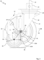
- Fig. 1 shows a known roller device 300 of a patient transport device (not shown) rolling over a surface 350.
- the patient transport device is a scissor lift table and has a patient support (not shown) in the form of a lying surface.
- the roller device 300 comprises a running wheel 302 which is held rotatably about a running wheel axis 306 by a wheel holder 304 in the form of a wheel fork.
- the wheel holder 304 is attached to the patient support.
- the base 350 is a base typical for helipads in hospitals or ships.
- the base 350 comprises a plurality of corrugated aluminum plates 352 that are arranged in a row.
- the corrugations of the aluminum plates prevent slipping when wet. This allows the patient transport device to be rolled over the base in a controlled manner.
- the corrugated aluminum plates 352 have a pattern 354 in the form of the corrugation of the corrugated aluminum plates 352.
- the pattern 354 is formed from a plurality of periodically repeating structures 356 in the form of individual corrugations of the corrugation.
- Each corrugation 356 comprises a plurality of projections 358.
- the projections 358 extend from a base 360 of the substrate 350 in the direction of the patient transport device with a height 362.
- Adjacent projections 358 of a corrugation 356 are spaced apart 364.
- Each corrugation 356 has a structure width SB. Two adjacent corrugations 356 are spaced apart from one another by a structure distance SA.
- Fig. 1 shows that the structural distance SA is designed such that the impeller 302 is immersed in a space between two adjacent corrugations 356 with 100% of the height 362 of the projections 358. Therefore, the impeller 302 contacts the base 360.
- the impeller 302 rolls over a groove 356 of the corrugated aluminum plates 352. Since the impeller 302, when rolling over a corrugation 356, penetrates less than 5% of the height 362 of the projections 358 into the corrugation 356, the distance 364 of the adjacent projections 358 of a corrugation 356 is not a structural distance and the projections 358 are not structures.
- the impeller 302 when rolling over a corrugation 356, penetrates less than 5% of the height 362 of the projections 358 into a space between adjacent projections 358 of a corrugation 356, the distance 364 of the adjacent projections 358 of a corrugation 356 is not a structural distance and the projections 358 are not structures.
- the impeller 302 then plunges into the space between two adjacent grooves 356 such that the impeller 302 contacts the base 360.
- the impeller 302 then rolls over another groove 356. This creates shocks that are transmitted to the patient holder and thus to a patient picked up with the patient holder.
- Fig. 2 shows a roller device 10 according to the invention for a patient transport device with a patient holder for rolling the patient transport device over a surface.
- the roller device 10 has a wheel holder 12, a running wheel 14 and a support wheel 16.
- the running wheel 14 is held by the wheel holder 12 so that it can rotate about a running wheel axis 18.
- the support wheel 16 is held by the wheel holder 12 so that it can rotate about a support wheel axis 20.
- the wheel holder 12 holds the running wheel 14 and the support wheel 16 such that the The running wheel axis 18 and the support wheel axis 20 are fixed relative to one another.
- the running wheel axis 18 and the support wheel axis 20 are arranged parallel and offset from one another.
- the wheel holder 12 keeps a distance between the patient support and the wheel axle 18 and a distance between the patient support and the support wheel axle 20 constant.
- the wheel holder 12 can be connected to the patient support so that it can rotate about a pivot axis 22.
- the connection between the roller device 10 and the patient support is made by means of a screw connection.
- the roller device 10 has a cuboid-shaped pin 24 which is inserted into a corresponding receptacle of the patient support and fixed within the receptacle by means of a screw.
- the roller device 10 has a pivot bearing 28.
- the pivot bearing 28 is arranged between the pin 24 and the running wheel axle 18 and between the pin 24 and the support wheel axle 20.
- the wheel holder 12 can be rotatably connected to the patient support so that the running wheel axle 18 and the support wheel axle 20 can rotate about the pivot axis 22.
- the pivot axis 22 is a vertical pivot axis.
- the pivot axis 22 is perpendicular to a rolling direction 26.
- the rolling direction 26 is a direction in which a patient transport device equipped with the roller device 10 is rolled.
- the pivot axis 22 is perpendicular to the running wheel axis 18 and the support wheel axis 20.
- the wheel holder 12 has a wheel fork 30 for the running wheel 14 and a wheel fork 32 for the support wheel 16.
- the running wheel 14 is held by the wheel fork 30 for the running wheel 14 so that it can rotate about the running wheel axis 18.
- the support wheel 16 is held by the wheel fork 30 for the support wheel 16 so that it can rotate about the support wheel axis 20.
- the wheel fork 30 for the running wheel 14 and the wheel fork 32 for the support wheel 16 are designed as separate components.
- the roller device 10 has fastening elements 34 in the form of screws which connect the wheel fork 30 for the running wheel 14 and the wheel fork 32 for the support wheel 16 to one another, in particular by means of a screw connection.
- the running wheel 14 and the support wheel 16 define a rolling plane 36.
- the rolling plane 36 is a tangential plane relative to a running surface of the running wheel 14 and relative to a running surface of the support wheel 16.
- the rolling plane 36 is a horizontal plane.
- the rolling plane 36 runs parallel to a flat surface when the roller device 10 rolls over the flat surface. When the roller device 10 rolls over the flat surface, the level surface within the rolling plane 36.
- the rolling plane 36 is parallel and offset to the running wheel axis 18 and the support wheel axis 20.
- the rolling plane 36 is perpendicular to the pivot axis 22.
- a rotation axis distance DA between the impeller axle 18 and the support wheel axle 20 is smaller than the sum of a radius RL of the impeller 14 and a radius RS of the support wheel 16.
- the following formula applies to the rotation axis distance DA: DA ⁇ RL + RS.
- the rotation axis distance DA is smaller than the radius RL of the impeller 14.
- the rotation axis distance DA can be broken down into a horizontal rotation axis distance HDA and a vertical rotation axis distance VDA.
- the horizontal rotation axis distance HDA and the vertical rotation axis distance VDA are to be determined orthogonally to one another.
- the horizontal rotation axis distance HDA is to be determined parallel to the rolling direction 26, perpendicular to the swivel axis 22, perpendicular to the running wheel axis 18, perpendicular to the support wheel axis 20 and parallel to the rolling plane 36.
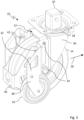
- Fig. 3 shows the roller device 10 in an oblique view.
- the wheel fork 32 for the support wheel 16 is a bent part.
- the wheel fork 32 for the support wheel 16 comprises a first bent sheet 38 and a second bent sheet 40.
- the first bent sheet 38 is connected to the second bent sheet 40 by means of a screw connection 42.
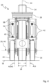
- Fig. 4 shows the roller device 10 from the rear.
- the running wheel 14 has a running wheel width LB.
- the running wheel width LB is to be determined in the direction of the running wheel axis 18.
- the support wheel 16 is spaced apart from the running wheel 14 by a distance ALS.
- the roller device 10 has a further support wheel 44, which is held by the wheel holder 12 so that it can rotate about a further support wheel axis 46.
- the further support wheel axis 46 and the support wheel axis 20 are the same, in particular a course of the further support wheel axis 46 and a course of the support wheel axis 20 are identical.
- the further support wheel 44 and the support wheel 16 are of identical construction.
- the running wheel 14 is arranged centrally between the support wheel 16 and the further support wheel 44.
- the further support wheel 44 is spaced apart from the running wheel 14 by a further distance ALWS.
- Fig. 5 to 9 show a roller system 500 comprising the substrate 350 and the roller device 10.
- Fig. 5 to 8 show the roller device 10 rolling in the rolling direction 26 over the ground 350 of Fig. 1 .
- the roller device 10 rolls perpendicular to an extension of the projections 358.
- the horizontal rotation axis distance HDA is adapted to the pattern 354 in such a way that when the roller device 10 rolls over the substrate 350 at least the impeller 14 or the support wheel 16 is in contact with at least one of two adjacent structures 356.
- the structure width SB is smaller than the structure spacing SA.
- the horizontal rotation axis spacing HDA is larger than the structure width SB and smaller than the structure spacing SA.
- the horizontal rotation axis spacing HDA has a value WT that is calculated from one third of the sum of the structure spacing SA and twice the structure width SB.
- the impeller 14 is in contact with one of the grooves 356.
- the support wheel 16 is not in contact with the groove 356.
- the support wheel 16 can be immersed between two adjacent grooves 356 by a maximum of 4% of the height 362 of the projections 358, since the wheel holder 12 holds the impeller 14 and the support wheel 16 in such a way that the impeller axis 18 and the support wheel axis 20 are fixed relative to one another.
- Fig. 7 the support wheel 16 is in contact with the grooves 356.
- the impeller 14 is not in contact with the grooves 356.
- the impeller 14 can only penetrate up to 4% of the height 362 of the projections 358 between two adjacent grooves 356, since the wheel holder 12 holds the impeller 14 and the support wheel 16 in such a way that the impeller axis 18 and the support wheel axis 20 are fixed relative to one another.
- Fig. 9 shows the roller device 10 rolling over the ground 350.
- the roller device 10 rolls in a rolling direction 26 rotated by 90° about the pivot axis 22.
- a rear side of the roller device 10 can be seen.
- a sum of the distance ALS between the running wheel 14 and the support wheel 16, the running wheel width LB and the further distance ALWS between the running wheel 14 and the further support wheel 44 is greater than the structural distance SA and smaller than a sum of the structural distance SA and twice the structural width SB.
- the following relationship applies: ALS + LB + ALWS ⁇ SA + 2*SB and ALS + LB + ALWS ⁇ SA.
- such an arrangement of the running wheel 14, the support wheel 16 and the further support wheel 44 This ensures that none of the wheels 14, 16, 44 dips between two adjacent grooves 356 even when the rolling direction 26 changes. This prevents shocks from occurring when the roller device 10 rolls over the ground 350 in any rolling direction 26.
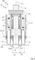
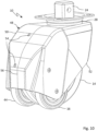
- Fig. 10 shows the roller device 10 with a housing 48.
- the housing 48 comprises a first housing half 50 and a second housing half 52.
- the first housing half 50 is connected to the second housing half 52 by means of a screw connection 54.
- a dividing plane 56 of the housing runs parallel to the impeller.
- the housing 48 completely covers the wheel holder and thus prevents dirt from outside from reaching the wheel holder.
- a patient transport device (not shown) for transporting a patient has a patient support for receiving the patient and at least one roller device as described above.
- the wheel holder is connected to the patient support so that it can rotate about the pivot axis or is fixedly connected.
- the invention provides a roller device, a patient transport device and a roller system which increase comfort when rolling the roller device.
Landscapes
- Engineering & Computer Science (AREA)
- Mechanical Engineering (AREA)
- Rollers For Roller Conveyors For Transfer (AREA)
Abstract
Description
- Die Erfindung betrifft eine Rollenvorrichtung, eine Patiententransportvorrichtung und ein Rollensystem.
- Hubschrauberlandeplätze von Kliniken oder Schiffen, insbesondere Dachlandeplätze oder Decklandeplätze, werden häufig mit geriffelten Aluminiumplatten oder Gitterelementen, beispielsweise Gitterrosten, ausgerüstet. Insbesondere werden derartige Elemente oft als Untergrund für eine Auffahrtsrampe, die zu einer Landeplattform des Hubschrauberlandeplatzes führt, verwendet. Dabei verhindert die Riffelung der Aluminiumplatten oder das Gitter der Gitterelemente ein Rutschen, insbesondere bei Nässe. Daher wird eine Rutschfestigkeit durch die Riffelung und/oder durch das Gitter verbessert.
- Rollenvorrichtungen werden häufig bei Patiententransportvorrichtungen mit einer Patientenaufnahme zum Rollen über einen Untergrund verwendet. Die Patientenaufnahme kann eine Liegefläche oder eine Sitzfläche für einen Patienten umfassen oder sein. Die Patiententransportvorrichtung kann eine Liege, ein Bett, insbesondere ein Krankenhausbett, ein Sitz, insbesondere ein Rollstuhl, ein Tisch, insbesondere ein Hubtisch oder ein Scherenhubtisch, oder eine Trage, insbesondere eine Krankentrage, eine Trageliege oder ein Tragestuhl, umfassen oder sein.
- Beim Rollen der Patiententransportvorrichtung mittels Rollenvorrichtungen über geriffelte Aluminiumplatten oder Gitterelemente entstehen aufgrund den Riffelungen der Aluminiumplatten oder den Gittern der Gitterelemente typischerweise Stöße, welche auf die Patientenaufnahme und damit auf einen mit der Patientenaufnahme aufgenommenen Patienten übertragen werden.
- Es ist Aufgabe der vorliegenden Erfindung, eine Rollenvorrichtung für eine Patiententransportvorrichtung bereitzustellen, die verbesserte Eigenschaften hat, insbesondere die beim Rollen der Rollenvorrichtung den Komfort für den Patienten erhöht. Weiter ist es Aufgabe der vorliegenden Erfindung, eine Patiententransportvorrichtung und ein Rollensystem bereitzustellen, die jeweils eine derartige Rollenvorrichtung umfassen.
- Die Erfindung löst diese Aufgaben durch die Merkmale des Anspruchs 1, des Anspruchs 10 und des Anspruchs 11. Vorteilhafte Ausgestaltungen und Weiterbildungen der Erfindung ergeben sich aus den abhängigen Ansprüchen.
- Eine erfindungsgemäße Rollenvorrichtung für eine Patiententransportvorrichtung mit einer Patientenaufnahme zum Rollen der Patiententransportvorrichtung über einen Untergrund weist eine Radhalterung, ein Laufrad und ein Stützrad auf. Die Radhalterung ist um eine Schwenkachse drehbar oder fest mit der Patientenaufnahme verbindbar. Das Laufrad ist von der Radhalterung um eine Laufradachse drehbar gehalten. Das Stützrad ist von der Radhalterung um eine Stützradachse drehbar gehalten. Die Laufradachse und die Stützradachse sind parallel und versetzt zueinander angeordnet.
- Vorteilhafterweise wird durch die parallele und versetzte Anordnung der Laufradachse und der Stützradachse zueinander ein Eintauchen des Laufrads in einen Zwischenraum zwischen zwei benachbarter Riffel einer geriffelten Aluminiumplatte oder in einen Durchbruch eines Gitters der Gitterelemente reduziert oder ganz vermieden. Dadurch wird die Entstehung von Stößen beim Rollen der Rollenvorrichtung über geriffelte Aluminiumplatten oder Gitterelemente reduziert oder ganz vermieden. Somit wird beim Rollen der Rollenvorrichtung ein Komfort erhöht.
- Der Untergrund kann ein Muster aufweisen. Das Muster kann aus einer Mehrzahl von sich periodisch wiederholender Strukturen gebildet sein. Jede Struktur kann eine Strukturbreite aufweisen. Zwei benachbarte Strukturen können mit einem Strukturabstand voneinander beabstandet sein. Der Strukturabstand kann derart ausgebildet sein, dass ein Laufrad einer nur das Laufrad aufweisenden Rollenvorrichtung mit mindestens 5%, insbesondere 10% oder 20%, einer Höhe, insbesondere der niedrigsten Struktur, der beiden benachbarten Strukturen zwischen den beiden benachbarten Strukturen eintauchen kann.
- Der Untergrund kann geriffelte Platten, vorzugsweise geriffelte Aluminiumplatten, und/oder Gitterelemente aufweisen. Das Muster kann eine Riffelung der geriffelten Platten oder ein Gitter der Gitterelemente sein. Die Struktur kann ein einziges Riffel der Riffelung oder ein einziger Durchbruch des Gitters sein. Das einzige Riffel kann mehrere Vorsprünge umfassen. Der Strukturabstand kann ein Abstand zwischen benachbarter Riffel oder Durchbrüche sein.
- Die Radhalterung kann eine Radgabel für das Laufrad umfassen. Das Laufrad kann von der Radgabel für das Laufrad um die Laufradachse drehbar gehalten sein. Die Radhalterung kann eine Radgabel für das Stützrad umfassen. Das Stützrad kann von der Radgabel für das Stützrad um die Stützradachse drehbar gehalten sein. Die Radhalterung kann einteilig ausgeführt sein. Alternativ kann die Radhalterung mehrere voneinander getrennte Bauteile umfassen. Die Radhalterung kann derart das Laufrad und das Stützrad halten, dass die Laufradachse und die Stützradachse relativ zueinander festgelegt sind. Unter die Laufradachse und die Stützradachse sind relativ zueinander festgelegt kann verstanden werden, dass beim Rollen der Rollenvorrichtung über einen Untergrund eine Position und/oder eine Lage der Laufradachse und eine Position und/oder eine Lage der Stützradachse relativ zueinander unveränderlich sind.
- Die Radhalterung kann dazu ausgebildet sein, einen Abstand zwischen einer mit der Rollenvorrichtung verbundenen Patientenaufnahme und der Laufradachse und einen Abstand zwischen der mit der Rollenvorrichtung verbundenen Patientenaufnahme und der Stützradachse während des Rollens der Rollenvorrichtung konstant zu halten.
- Die Verbindung zwischen der Radhalterung und der Patientenaufnahme kann mittels einer Schraubverbindung, einer formschlüssigen Verbindung und/oder einer kraftschlüssigen Verbindung hergestellt werden. Die Rollenvorrichtung kann einen, insbesondere zylinderförmigen oder quaderförmigen, Zapfen zum Verbinden der Radhalterung mit der Patientenaufnahme aufweisen. Der Zapfen kann an der Radhalterung angeordnet sein. Der Zapfen kann für das Herstellen der Schraubverbindung, der formschlüssigen Verbindung und/oder der kraftschlüssigen Verbindung, insbesondere mit der Patientenaufnahme, ausgebildet sein.
- Die Rollenvorrichtung kann ein Drehlager aufweisen. Das Drehlager kann an der Radhalterung angeordnet sein. Das Drehlager kann zwischen dem Zapfen und der Laufradachse und/oder der Stützradachse angeordnet sein. Die Radhalterung kann mittels des Drehlagers um die Schwenkachse drehbar sein. Mittels des Drehlagers können die Laufradachse und die Stützradachse um die Schwenkachse gedreht werden, insbesondere können die Laufradachse und die Stützradachse relativ zu einer mit der Rollenvorrichtung verbundenen Patientenaufnahme um die Schwenkachse gedreht werden.
- Die Schwenkachse kann eine vertikale Schwenkachse sein. Die Schwenkachse kann senkrecht zu einer Rollrichtung angeordnet sein. Die Rollrichtung kann eine Richtung sein, in welche die Rollenvorrichtung gerollt werden kann. Insbesondere kann die Rollrichtung eine Richtung sein, in welche eine mit der Rollenvorrichtung ausgestatteten Patiententransportvorrichtung gerollt werden kann. Zusätzlich oder alternativ kann die Schwenkachse senkrecht zu der Laufradachse und der Stützradachse angeordnet sein.
- Das Stützrad kann mit einem Abstand, insbesondere in Richtung der Laufradachse, von dem Laufrad beabstandet sein. Der Abstand kann parallel zu der Laufradachse ermittelt werden. Der Abstand kann beispielsweise 0,5 cm bis 6 cm, insbesondere 1 cm bis 3 cm, betragen. Die Abkürzung cm kann die Einheit Zentimeter bezeichnen.
- Die Rollenvorrichtung kann ein Gehäuse, insbesondere eine Abdeckung, aufweisen. Das Gehäuse kann eine erste Gehäusehälfte und eine zweite Gehäusehälfte umfassen. Die erste Gehäusehälfte kann mittels einer Schraubverbindung oder einer Rastverbindung mit der zweiten Gehäusehälfte verbunden sein. Das Gehäuse kann die Radhalterung zumindest teilweise oder vollständig überdecken. Eine Teilungsebene des Gehäuses kann parallel zu dem Laufrad sein. Vorteilhafterweise kann das Gehäuse verhindern, dass Schmutz zu der Laufradachse und/oder zu der Stützradachse gelangt.
- In einer Weiterbildung der Rollenvorrichtung definiert das Laufrad und das Stützrad eine Rollebene. Die Rollebene kann eine Tangentialebene, insbesondere einer Lauffläche, des Laufrads und, insbesondere einer Lauffläche, des Stützrads sein. Die Rollebene kann eine horizontale Rollebene sein. Die Rollebene kann parallel zu einem, insbesondere ebenen, Untergrund sein, insbesondere beim Rollen der Rollenvorrichtung über den, insbesondere ebenen, Untergrund. Der, insbesondere ebene, Untergrund kann innerhalb der Rollebene liegen, insbesondere beim Rollen der Rollenvorrichtung über den, insbesondere ebenen, Untergrund. Die Rollebene kann parallel und versetzt zu der Laufradachse und der Stützradachse sein. Die Rollebene kann senkrecht zu der Schwenkachse und/oder einer Längsachse des Zapfens sein.
- In einer Weiterbildung der Rollenvorrichtung ist ein Drehachsenabstand zwischen der Laufradachse und der Stützradachse kleiner als die Summe aus einem Radius des Laufrads und einem Radius des Stützrads. Für den Drehachsenabstand kann die Formel gelten: DA ≤ RL + RS, wobei DA den Drehachsenabstand, RL den Radius des Laufrads und RS den Radius des Stützrads beschreibt.
- In einer Weiterbildung der Rollenvorrichtung ist der Drehachsenabstand zwischen der Laufradachse und der Stützradachse kleiner als ein Radius des Laufrads und/oder kleiner als ein Radius des Stützrads. Vorteilhafterweise ergibt sich dadurch eine besonders kompakte Bauweise der Rollenvorrichtung.
- In einer Weiterbildung der Rollenvorrichtung weist die Radhalterung eine Laufradhalterung und eine Stützradhalterung auf. Das Laufrad ist von der Laufradhalterung um die Laufradachse drehbar gehalten. Das Stützrad ist von der Stützradhalterung um die Stützradachse drehbar gehalten. Die Laufradhalterung und die Stützradhalterung sind lösbar miteinander verbunden. Vorteilhafterweise ermöglicht das lösbare Verbinden ein Nachrüsten des Stützrads an einer bestehenden Rollenvorrichtung, die nur das Laufrad umfasst.
- Die Laufradhalterung kann eine Radgabel für das Laufrad umfassen. Das Laufrad kann von der Radgabel für das Laufrad um die Laufradachse drehbar gehalten sein. Die Stützradhalterung kann eine Radgabel für das Stützrad umfassen. Das Stützrad kann von der Radgabel für das Stützrad um die Stützradachse drehbar gehalten sein. Die Rollenvorrichtung kann eine Befestigungseinrichtung zum lösbaren Verbinden der Laufradhalterung und der Stützradhalterung miteinander umfassen. Die Befestigungseinrichtung kann dazu ausgebildet sein, eine Schraubverbindung, eine formschlüssige Verbindung und/oder eine kraftschlüssige Verbindung zum lösbaren Verbinden der Laufradhalterung mit der Stützradhalterung herzustellen.
- In einer Weiterbildung der Rollenvorrichtung weist der Untergrund ein Muster auf. Das Muster ist aus einer Mehrzahl von sich periodisch wiederholender Strukturen gebildet. Jede Struktur weist eine Strukturbreite auf und zwei benachbarte Strukturen sind mit einem Strukturabstand voneinander beabstandet. Ein horizontaler Drehachsenabstand zwischen der Laufradachse und der Stützradachse ist gleich oder größer als die Strukturbreite und gleich oder kleiner als der Strukturabstand, wenn die Strukturbreite gleich oder kleiner als der Strukturabstand ist. Alternativ ist ein horizontaler Drehachsenabstand zwischen der Laufradachse und der Stützradachse gleich oder kleiner als die Strukturbreite und gleich oder größer als der Strukturabstand, wenn die Strukturbreite größer als der Strukturabstand ist. Alternativ oder Zusätzlich beträgt der horizontaler Drehachsenabstand 95% bis 110%, insbesondere 98% bis 106% eines Werts, der sich aus einem Drittel einer Summe aus dem Strukturabstand und dem Doppelten der Strukturbreite berechnet.
- Der Strukturabstand kann für alle benachbarten Strukturen des Musters gleich sein. Der Drehachsenabstand kann in den horizontalen Drehachsenabstand und in einen vertikalen Drehachsenabstand zerlegt werden. Der horizontale Drehachsenabstand und der vertikale Drehachsenabstand können orthogonal zueinander ermittelt werden. Der horizontale Drehachsenabstand kann parallel zu der Rollrichtung ermittelt werden. Der horizontale Drehachsenabstand kann senkrecht zu der Schwenkachse ermittelt werden. Der horizontale Drehachsenabstand kann senkrecht zu der Laufradachse und/oder zu der Stützradachse ermittelt werden. Der horizontale Drehachsenabstand kann parallel zu der Rollebene ermittelt werden.
- Für den Wert, der sich aus einem Drittel einer Summe aus dem Strukturabstand und dem Doppelten der Strukturbreite berechnet, kann die Formel gelten: WT = (SA + 2*SB) / 3, wobei WT den Wert, SA den Strukturabstand und SB die Strukturbreite beschreibt.
- Der horizontale Drehachsenabstand kann derart auf das Muster abgestimmt sein, dass beim Rollen der Rollenvorrichtung über den Untergrund das Laufrad und/oder das Stützrad mit mindestens einer von zwei benachbarten Strukturen in Kontakt ist. Der horizontale Drehachsenabstand kann derart auf das Muster abgestimmt sein, dass das Laufrad und/oder das Stützrad mit höchstens 20%, insbesondere 10% oder 5%, einer Höhe, insbesondere der niedrigsten Struktur, von zwei benachbarten Strukturen zwischen den zwei benachbarten Strukturen eintauchen kann.
- In einer Weiterbildung der Rollenvorrichtung weist die Rollenvorrichtung ein weiteres Stützrad auf, das von der Radhalterung um eine weitere Stützradachse drehbar gehalten ist. Die weitere Stützradachse kann parallel und versetzt zu der Stützradachse sein. Die weitere Stützradachse und die Stützradachse können gleich sein, insbesondere kann die weitere Stützradachse die Stützradachse sein. Das weitere Stützrad und das Stützrad können gleich ausgebildet, insbesondere baugleich, sein. Das weitere Stützrad kann alle oder einige zuvor beschriebene Merkmale des Stützrads aufweisen. Deshalb kann die vorstehende Beschreibung des Stützrads ganz oder teilweise korrespondierend für das weitere Stützrad gelten.
- In einer Weiterbildung der Rollenvorrichtung ist das Laufrad zwischen dem Stützrad und dem weiteren Stützrad angeordnet ist. Das Laufrad kann mittig zwischen dem Stützrad und dem weiteren Stützrad angeordnet sein. Das weitere Stützrad kann mit einem weiteren Abstand von dem Laufrad beabstandet sein. Der weitere Abstand kann parallel zu der Laufradachse ermittelt werden. Der weitere Abstand kann beispielsweise 0,5 cm bis 6 cm, insbesondere 1 cm bis 3 cm, betragen. Eine Summe aus dem Abstand zwischen dem Laufrad und dem Stützrad, einer Laufradbreite des Laufrads und dem weiteren Abstand zwischen dem Laufrad und dem weiteren Stützrad kann gleich oder größer sein als der Strukturabstand und/oder kann gleich oder kleiner sein als eine Summe aus Strukturabstand und der doppelten Strukturbreite. Es kann folgende Beziehung gelten: ALS + LB + ALWS ≤ SA + 2*SB und/oder ALS + LB + ALWS ≥ SA, wobei ALS den Abstand zwischen dem Laufrad und dem Stützrad, LB die Laufradbreite, ALWS den weiteren Abstand zwischen dem Laufrad und dem weiteren Stützrad, SA den Strukturabstand und SB die Strukturbreite beschreibt.
- Eine erfindungsgemäße Patiententransportvorrichtung zum Transportieren eines Patienten weist eine Patientenaufnahme zum Aufnehmen des Patienten und mindestens eine zuvor beschriebene Rollenvorrichtung auf. Die Radhalterung ist mit der Patientenaufnahme drehbar um die Schwenkachse oder fest verbunden. Die Patiententransportvorrichtung kann vier, sechs oder acht Rollenvorrichtungen aufweisen. Die Rollenvorrichtungen können an einer Ecke oder innerhalb eines Eckbereichs der Patientenaufnahme angeordnet sein.
- Ein erfindungsgemäßes Rollensystem weist ein Untergrund mit einem Muster auf. Das Muster ist aus einer Mehrzahl von sich periodisch wiederholender Strukturen gebildet. Jede Struktur weist eine Strukturbreite auf und zwei benachbarte Strukturen sind mit einem Strukturabstand voneinander beabstandet. Weiter umfasst das Rollensystem eine zuvor beschriebene Rollenvorrichtung oder eine zuvor beschriebene Patiententransportvorrichtung.
- Weitere Vorteile und vorteilhafte Ausgestaltungen der Erfindung sind den nachfolgenden Zeichnungen, deren Beschreibung und den Patentansprüchen entnehmbar. Alle in den Zeichnungen, deren Beschreibung und den Patentansprüchen offenbarten Merkmale können sowohl einzeln als auch in beliebiger Kombination miteinander erfindungswesentlich sein. Es zeigen:
-
Fig. 1 eine schematische Darstellung einer bekannten Rollenvorrichtung beim Rollen über einen Untergrund, -
Fig. 2 eine schematische Seitenansicht einer erfindungsgemäßen Rollenvorrichtung, -
Fig. 3 eine schematische Schrägansicht der Rollenvorrichtung vonFig. 2 , -
Fig. 4 eine schematische Rückansicht der Rollenvorrichtung vonFig. 2 , -
Fig. 5 bis 8 eine schematische Darstellung der Rollenvorrichtung vonFig. 2 beim Rollen über den Untergrund, -
Fig. 9 eine weitere schematische Darstellung der Rollenvorrichtung vonFig. 2 beim Rollen über den Untergrund in eine vonFig. 5 bis 8 unterschiedliche Rollrichtung, und -
Fig. 10 eine schematische Darstellung der Rollenvorrichtung mit einem Gehäuse. -
Fig. 1 zeigt eine bekannte Rollenvorrichtung 300 einer nicht dargestellten Patiententransportvorrichtung beim Rollen über einen Untergrund 350. Die - Patiententransportvorrichtung ist ein Scherenhubtisch und hat eine nicht dargestellte Patientenaufnahme in Form einer Liegefläche. Die Rollenvorrichtung 300 umfasst ein Laufrad 302, das mit einer Radhalterung 304 in Form einer Radgabel um eine Laufradachse 306 drehbar gehalten ist. Die Radhalterung 304 ist an der Patientenaufnahme befestigt.
- Der Untergrund 350 ist ein für Hubschrauberlandeplätze von Kliniken oder Schiffen typischer Untergrund. Der Untergrund 350 umfasst eine Mehrzahl von geriffelten Aluminiumplatten 352, die aneinandergereiht sind. Die Riffelung der Aluminiumplatten verhindern bei Nässe ein Rutschen. Dadurch kann die Patiententransportvorrichtung kontrolliert über den Untergrund gerollt werden.
- Die geriffelten Aluminiumplatten 352 haben ein Muster 354 in Form der Riffelung der geriffelten Aluminiumplatten 352. Das Muster 354 ist aus einer Mehrzahl von sich periodisch wiederholender Strukturen 356 in Form von einzelner Riffel der Riffelung gebildet. Jedes Riffel 356 umfasst mehrere Vorsprünge 358. Die Vorsprünge 358 erstrecken sich von einem Grund 360 des Untergrunds 350 in Richtung der Patiententransportvorrichtung mit einer Höhe 362. Benachbarte Vorsprünge 358 eines Riffels 356 haben einen Abstand 364 zueinander. Jedes Riffel 356 hat eine Strukturbreite SB. Zwei benachbarte Riffel 356 sind mit einem Strukturabstand SA voneinander beabstandet.
-
Fig. 1 zeigt, dass der Strukturabstand SA derart ausgebildet ist, dass das Laufrad 302 in einen Zwischenraum zwischen zwei benachbarter Riffel 356 mit 100% der Höhe 362 der Vorsprünge 358 eintaucht. Daher kontaktiert das Laufrad 302 den Grund 360. - Beim Rollen der Rollenvorrichtung 300 über den Untergrund 350 rollt das Laufrad 302 über ein Riffel 356 der geriffelten Aluminiumplatten 352. Da das Laufrad 302 beim Rollen über ein Riffel 356 weniger als 5% der Höhe 362 der Vorsprünge 358 in das Riffel 356 eintaucht, ist der Abstand 364 der benachbarten Vorsprünge 358 eines Riffels 356 kein Strukturabstand und die Vorsprünge 358 sind keine Strukturen. Anders formuliert: Da das Laufrad 302 beim Rollen über ein Riffel 356 weniger als 5% der Höhe 362 der Vorsprünge 358 in einen Zwischenraum zwischen benachbarter Vorsprünge 358 eines Riffels 356 eintaucht, ist der Abstand 364 der benachbarten Vorsprünge 358 eines Riffels 356 kein Strukturabstand und die Vorsprünge 358 sind keine Strukturen. Anschließend taucht das Laufrad 302 in den Zwischenraum zwischen zwei benachbarter Riffel 356 derart ein, dass das Laufrad 302 den Grund 360 kontaktiert. Danach rollt das Laufrad 302 über ein weiteres Riffel 356. Dabei entstehen Stöße, die auf die Patientenaufnahme und damit auf einen mit der Patientenaufnahme aufgenommenen Patienten übertragen werden.
-
Fig. 2 zeigt eine erfindungsgemäße Rollenvorrichtung 10 für eine Patiententransportvorrichtung mit einer Patientenaufnahme zum Rollen der Patiententransportvorrichtung über einen Untergrund. - Die Rollenvorrichtung 10 hat eine Radhalterung 12, ein Laufrad 14 und ein Stützrad 16. Das Laufrad 14 ist von der Radhalterung 12 um eine Laufradachse 18 drehbar gehalten. Das Stützrad 16 ist von der Radhalterung 12 um eine Stützradachse 20 drehbar gehalten. Die Radhalterung 12 hält das Laufrad 14 und das Stützrad 16 derart, dass die Laufradachse 18 und die Stützradachse 20 relativ zueinander festgelegt sind. Die Laufradachse 18 und die Stützradachse 20 sind parallel und versetzt zueinander angeordnet. Beim Rollen der Rollenvorrichtung 10 über einen Untergrund dreht sich das Laufrad 14 um die Laufradachse 18 und das Stützrad 16 um die Stützradachse 20, wenn das Laufrad 14 und das Stützrad 16 den Untergrund kontaktieren.
- Beim Rollen der Rollenvorrichtung 10 über einen Untergrund wird durch die Radhalterung 12 ein Abstand zwischen der Patientenaufnahme und der Laufradachse 18 und einen Abstand zwischen der Patientenaufnahme und der Stützradachse 20 konstant gehalten.
- Die Radhalterung 12 ist um eine Schwenkachse 22 drehbar mit der Patientenaufnahme verbindbar. Die Verbindung zwischen der Rollenvorrichtung 10 und der Patientenaufnahme wird mittels einer Schraubverbindung hergestellt. Hierzu hat die Rollenvorrichtung 10 einen quaderförmigen Zapfen 24, der in eine korrespondierende Aufnahme der Patientenaufnahme eingesteckt und mittels einer Schraube innerhalb der Aufnahme fixiert wird.
- Die Rollenvorrichtung 10 hat ein Drehlager 28. Das Drehlager 28 ist zwischen dem Zapfen 24 und der Laufradachse 18 und zwischen dem Zapfen 24 und der Stützradachse 20 angeordnet. Mittels des Drehlagers 18 ist die Radhalterung 12 drehbar mit der Patientenaufnahme verbindbar, so dass die Laufradachse 18 und die Stützradachse 20 um die Schwenkachse 22 drehbar sind.
- Die Schwenkachse 22 ist eine vertikale Schwenkachse. Die Schwenkachse 22 ist senkrecht zu einer Rollrichtung 26. Die Rollrichtung 26 ist eine Richtung, in welche eine mit der Rollenvorrichtung 10 ausgestatteten Patiententransportvorrichtung gerollt wird. Die Schwenkachse 22 ist senkrecht zu der Laufradachse 18 und der Stützradachse 20.
- Die Radhalterung 12 hat eine Radgabel 30 für das Laufrad 14 und eine Radgabel 32 für das Stützrad 16. Das Laufrad 14 ist von der Radgabel 30 für das Laufrad 14 um die Laufradachse 18 drehbar gehalten. Das Stützrad 16 ist von der Radgabel 30 für das Stützrad 16 um die Stützradachse 20 drehbar gehalten. Die Radgabel 30 für das Laufrad 14 und die Radgabel 32 für das Stützrad 16 sind als voneinander getrennte Bauteile ausgebildet. Die Rollenvorrichtung 10 hat Befestigungselemente 34 in Form von Schrauben, welche die Radgabel 30 für das Laufrad 14 und die Radgabel 32 für das Stützrad 16 miteinander, insbesondere mittels einer Schraubverbindung, verbinden.
- Das Laufrad 14 und das Stützrad 16 definieren eine Rollebene 36. Die Rollebene 36 ist eine Tangentialebene bezogen auf eine Lauffläche des Laufrads 14 und bezogen auf eine Lauffläche des Stützrads 16. Die Rollebene 36 ist eine horizontale Ebene. Die Rollebene 36 verläuft parallel zu einem ebenen Untergrund, wenn die Rollenvorrichtung 10 über den ebenen Untergrund rollt. Beim Rollen der Rollenvorrichtung 10 über den ebenen Untergrund, liegt der ebene Untergrund innerhalb der Rollebene 36. Die Rollebene 36 ist parallel und versetzt zu der Laufradachse 18 und der Stützradachse 20. Die Rollebene 36 ist senkrecht zu der Schwenkachse 22.
- Ein Drehachsenabstand DA zwischen der Laufradachse 18 und der Stützradachse 20 ist kleiner als die Summe aus einem Radius RL des Laufrads 14 und einem Radius RS des Stützrads 16. Für den Drehachsenabstand DA gilt die Formel: DA ≤ RL + RS. Zusätzlich ist der Drehachsenabstand DA kleiner als der Radius RL des Laufrads 14.
- Der Drehachsenabstand DA ist in einen horizontalen Drehachsenabstand HDA und in einen vertikalen Drehachsenabstand VDA zerlegbar. Der horizontale Drehachsenabstand HDA und der vertikale Drehachsenabstand VDA sind orthogonal zueinander zu ermitteln. Der horizontale Drehachsenabstand HDA ist parallel zu der Rollrichtung 26, senkrecht zu der Schwenkachse 22, senkrecht zu der Laufradachse 18, senkrecht zu der Stützradachse 20 und parallel zu der Rollebene 36 zu ermitteln.
-
Fig. 3 zeigt die Rollenvorrichtung 10 in einer Schrägansicht. InFig. 3 ist zu erkennen, dass die Radgabel 32 für das Stützrad 16 ein Biegeteil ist. Die Radgabel 32 für das Stützrad 16 umfasst ein erstes gebogenes Blech 38 und ein zweites gebogenes Blech 40. Das erste gebogene Blech 38 ist mit dem zweiten gebogene Blech 40 mittels einer Schraubverbindung 42 miteinander verbunden. -
Fig. 4 zeigt die Rollenvorrichtung 10 von einer Rückseite. Das Laufrad 14 hat eine Laufradbreite LB. Die Laufradbreite LB ist in Richtung der Laufradachse 18 zu ermitteln. Das Stützrad 16 ist mit einem Abstand ALS von dem Laufrad 14 beabstandet. - Die Rollenvorrichtung 10 hat ein weiteres Stützrad 44, das von der Radhalterung 12 um eine weitere Stützradachse 46 drehbar gehalten ist. Die weitere Stützradachse 46 und die Stützradachse 20 sind gleich, insbesondere ist ein Verlauf der weiteren Stützradachse 46 und ein Verlauf der Stützradachse 20 identisch. Das weitere Stützrad 44 und das Stützrad 16 sind baugleich.
- Das Laufrad 14 ist mittig zwischen dem Stützrad 16 und dem weiteren Stützrad 44 angeordnet. Das weitere Stützrad 44 ist mit einem weiteren Abstand ALWS von dem Laufrad 14 beabstandet.
-
Fig. 5 bis 9 zeigen ein Rollensystem 500, das den Untergrund 350 und die Rollenvorrichtung 10 umfasst. -
Fig. 5 bis 8 zeigen die Rollenvorrichtung 10 beim Rollen in Rollrichtung 26 über den Untergrund 350 vonFig. 1 . Die Rollenvorrichtung 10 rollt senkrecht zu einer Erstreckung der Vorsprünge 358. Der horizontale Drehachsenabstand HDA ist derart auf das Muster 354 abgestimmt, dass beim Rollen der Rollenvorrichtung 10 über den Untergrund 350 zumindest das Laufrad 14 oder das Stützrad 16 mit mindestens einer von zwei benachbarten Strukturen 356 in Kontakt ist. - Die Strukturbreite SB ist kleiner als der Strukturabstand SA. Der horizontaler Drehachsenabstand HDA ist größer als die Strukturbreite SB und kleiner als der Strukturabstand SA. Der horizontaler Drehachsenabstand HDA hat einen Wert WT, der sich aus einem Drittel einer Summe aus dem Strukturabstand SA und dem Doppelten der Strukturbreite SB berechnet. Der Wert WT des horizontalen Drehachsenabstands HDA berechnet sich nach: WT = (SA + 2*SB) / 3.
- Mit einem derartigen horizontalen Drehachsenabstand HDA wird ein Eintauchen des Laufrads 14, des Stützrads 16 und des Weiteren Stützrads 44 zwischen zwei benachbarter Riffel 356 des Untergrunds 350 vermieden. Dies verdeutlichen die
Fig. 5 bis 8 . - In
Fig. 5 ist das Laufrad 14 in Kontakt mit einem der Riffel 356. Das Stützrad 16 ist nicht mit dem Riffel 356 in Kontakt. Das Stützrad 16 kann höchstens bis zu 4% der Höhe 362 der Vorsprünge 358 zwischen zwei benachbarter Riffel 356 eintauchen, da die Radhalterung 12 das Laufrad 14 und das Stützrad 16 derart hält, dass die Laufradachse 18 und die Stützradachse 20 relativ zueinander festgelegt sind. - In
Fig. 6 ist das Laufrad 14 und das Stützrad 16 in Kontakt mit dem Riffel 356. - In
Fig. 7 ist das Stützrad 16 in Kontakt mit dem der Riffel 356. Das Laufrad 14 ist nicht mit dem Riffel 356 in Kontakt. Das Laufrad 14 kann höchstens bis zu 4% der Höhe 362 der Vorsprünge 358 zwischen zwei benachbarter Riffel 356 eintauchen, da die Radhalterung 12 das Laufrad 14 und das Stützrad 16 derart hält, dass die Laufradachse 18 und die Stützradachse 20 relativ zueinander festgelegt sind. - In
Fig. 8 ist das Stützrad 16 in Kontakt mit dem Riffel 356 und das Laufrad 14 ist in Kontakt mit einem zu dem Riffel 356 benachbarten Riffel 356. - Die Beschreibung der
Fig. 5 bis 8 hinsichtlich des Stützrads 16 gilt entsprechend für das weitere Stützrad 44. -
Fig. 9 zeigt die Rollenvorrichtung 10 beim Rollen über den Untergrund 350. Im Unterschied zu denFiguren 5 bis 8 rollt die Rollenvorrichtung 10 in eine um 90° um die Schwenkachse 22 gedrehte Rollrichtung 26. Dabei ist eine Rückseite der Rollenvorrichtung 10 erkennbar. - Eine Summe aus dem Abstand ALS zwischen dem Laufrad 14 und dem Stützrad 16, der Laufradbreite LB und dem weiteren Abstand ALWS zwischen dem Laufrad 14 und dem weiteren Stützrad 44 ist größer als der Strukturabstand SA und kleiner als eine Summe aus Strukturabstand SA und der doppelten Strukturbreite SB. Es gilt die Beziehung: ALS + LB + ALWS ≤ SA + 2*SB und ALS + LB + ALWS ≥ SA. Vorteilhafterweise wird durch eine derartige Anordnung des Laufrads 14, des Stützrads 16 und des Weiteren Stützrads 44 erreicht, dass keines der Räder 14, 16, 44 auch bei einer Änderung der Rollrichtung 26 zwischen zwei benachbarten Riffel 356 eintaucht. Dadurch wird das Entstehen von Stößen beim Rollen der Rollenvorrichtung 10 über den Untergrund 350 in einer beliebigen Rollrichtung 26 vermieden.
-
Fig. 10 zeigt die Rollenvorrichtung 10 mit einem Gehäuse 48. Das Gehäuse 48 umfasst eine erste Gehäusehälfte 50 und eine zweite Gehäusehälfte 52. Die erste Gehäusehälfte 50 ist mittels einer Schraubverbindung 54 mit der zweiten Gehäusehälfte 52 verbunden. Eine Teilungsebene 56 des Gehäuses verläuft parallel zu dem Laufrad. Das Gehäuse 48 überdeckt die Radhalterung vollständig und verhindert damit, dass Schmutz von außen zu der Radhalterung gelangt. - Eine nicht dargestellte erfindungsgemäße Patiententransportvorrichtung zum Transportieren eines Patienten weist eine Patientenaufnahme zum Aufnehmen des Patienten und mindestens eine zuvor beschriebene Rollenvorrichtung auf. Die Radhalterung ist mit der Patientenaufnahme drehbar um die Schwenkachse oder fest verbunden.
- Wie die gezeigten und erläuterten Ausführungsbeispiele deutlich machen, stellt die Erfindung eine Rollenvorrichtung, eine Patiententransportvorrichtung und ein Rollensystem bereit, die beim Rollen der Rollenvorrichtung einen Komfort erhöhen.
Claims (11)
- Rollenvorrichtung (10) für eine
Patiententransportvorrichtung mit einer Patientenaufnahme zum Rollen der Patiententransportvorrichtung über einen Untergrund (350), die Rollenvorrichtung (10) aufweisend:- eine Radhalterung (12), die um eine Schwenkachse (22) drehbar oder fest mit der Patientenaufnahme verbindbar ist,- ein Laufrad (14), das von der Radhalterung (12) um eine Laufradachse (18) drehbar gehalten ist, und- ein Stützrad (16), das von der Radhalterung (12) um eine Stützradachse (20) drehbar gehalten ist,- wobei die Laufradachse (18) und die Stützradachse (20) parallel und versetzt zueinander angeordnet sind. - Rollenvorrichtung (10) nach Anspruch 1,- wobei das Laufrad (14) und das Stützrad (16) eine Rollebene (36) definieren.
- Rollenvorrichtung (10) nach einem der vorhergehenden Ansprüche,- wobei ein Drehachsenabstand (DA) zwischen der Laufradachse (18) und der Stützradachse (20) gleich oder kleiner als die Summe aus einem Radius (RL) des Laufrads (14) und einem Radius (RS) des Stützrads (16) ist.
- Rollenvorrichtung (10) nach Anspruch 3,- wobei der Drehachsenabstand (DA) zwischen der Laufradachse (18) und der Stützradachse (20) kleiner als ein Radius (RL) des Laufrads (14) und/oder kleiner als ein Radius (RS) des Stützrads (16) ist.
- Rollenvorrichtung (10) nach einem der vorhergehenden Ansprüche,- wobei die Radhalterung (12) eine Laufradhalterung und eine Stützradhalterung aufweist,- wobei das Laufrad (14) von der Laufradhalterung um die Laufradachse (18) drehbar gehalten ist,- wobei das Stützrad (16) von der Stützradhalterung um die Stützradachse (20) drehbar gehalten ist,- wobei die Laufradhalterung und die Stützradhalterung lösbar miteinander verbunden sind.
- Rollenvorrichtung (10) nach einem der vorhergehenden Ansprüche,- wobei der Untergrund (350) ein Muster (354) aufweist,- wobei das Muster (354) aus einer Mehrzahl von sich periodisch wiederholender Strukturen (356) gebildet ist,- wobei jede Struktur (356) eine Strukturbreite (SB) aufweist und zwei benachbarte Strukturen (356) mit einem Strukturabstand (SA) voneinander beabstandet sind,- wobei ein horizontaler Drehachsenabstand (HDA) zwischen der Laufradachse (18) und der Stützradachse (20) gleich oder größer als die Strukturbreite (SB) und gleich oder kleiner als der Strukturabstand (SA) ist, wenn die Strukturbreite (SB) gleich oder kleiner als der Strukturabstand (SA) ist, oder- wobei ein horizontaler Drehachsenabstand (HDA) zwischen der Laufradachse (18) und der Stützradachse (20) gleich oder kleiner als die Strukturbreite (SB) und gleich oder größer als der Strukturabstand (SA) ist, wenn die Strukturbreite (SB) größer als der Strukturabstand (SA) ist, und/oder- wobei der horizontaler Drehachsenabstand (HDA) 95% bis 110% eines Werts (WT) beträgt, der sich aus einem Drittel einer Summe aus dem Strukturabstand (SA) und dem Doppelten der Strukturbreite (SB) berechnet.
- Rollenvorrichtung (10) nach einem der vorhergehenden Ansprüche,- wobei die Rollenvorrichtung (10) ein weiteres Stützrad (16) aufweist, das von der Radhalterung (12) um eine weitere Stützradachse (20) drehbar gehalten ist.
- Rollenvorrichtung (10) nach Anspruch 7,- wobei das Laufrad (14) zwischen dem Stützrad (16) und dem weiteren Stützrad (16) angeordnet ist.
- Rollenvorrichtung (10) nach einem der vorhergehenden Ansprüche, wobei die Rollenvorrichtung (10) ein Gehäuse (48) aufweist.
- Patiententransportvorrichtung zum Transportieren eines Patienten, die Patiententransportvorrichtung aufweisend:- eine Patientenaufnahme zum Aufnehmen des Patienten, und- mindestens eine Rollenvorrichtung (10) nach einem der vorhergehenden Ansprüche,- wobei die Radhalterung (12) mit der Patientenaufnahme drehbar um die Schwenkachse (22) oder fest verbunden ist.
- Rollensystem (500), aufweisend:- eine Rollenvorrichtung (10) nach einem der Ansprüche 1 bis 8 oder eine Patiententransportvorrichtung nach Anspruch 9, und den Untergrund (350).
Applications Claiming Priority (1)
| Application Number | Priority Date | Filing Date | Title |
|---|---|---|---|
| DE102023109295.2A DE102023109295A1 (de) | 2023-04-13 | 2023-04-13 | Rollenvorrichtung, Patiententransportvorrichtung und Rollensystem |
Publications (1)
| Publication Number | Publication Date |
|---|---|
| EP4445888A1 true EP4445888A1 (de) | 2024-10-16 |
Family
ID=90730357
Family Applications (1)
| Application Number | Title | Priority Date | Filing Date |
|---|---|---|---|
| EP24170084.8A Pending EP4445888A1 (de) | 2023-04-13 | 2024-04-12 | Rollenvorrichtung, patiententransportvorrichtung und rollensystem |
Country Status (2)
| Country | Link |
|---|---|
| EP (1) | EP4445888A1 (de) |
| DE (1) | DE102023109295A1 (de) |
Citations (4)
| Publication number | Priority date | Publication date | Assignee | Title |
|---|---|---|---|---|
| EP1318028B1 (de) * | 2001-12-05 | 2006-08-09 | Schwarzwälder-Service Industrie- u. Gebäudereinigungsges. mbH & Co. | Rollenvorrichtung für einen Transportwagen |
| US20130127233A1 (en) * | 2013-01-18 | 2013-05-23 | Ktech Concepts, Llc | Obstacle Traversing Wheel Assembly |
| EP2946757B1 (de) * | 2014-05-20 | 2017-04-05 | Medicatlantic | Krankenbett mit einer angehobenen Position, die Querbewegungen an der Kopfseite erlaubt |
| JP6155120B2 (ja) * | 2013-07-08 | 2017-06-28 | 有限会社さいとう工房 | キャスタ及び車椅子 |
Family Cites Families (5)
| Publication number | Priority date | Publication date | Assignee | Title |
|---|---|---|---|---|
| US20030122327A1 (en) | 2001-12-28 | 2003-07-03 | Wu Donald P.H. | Miracle curb climber |
| JP2005132322A (ja) | 2003-10-31 | 2005-05-26 | Nippon Clean Engine Lab Co Ltd | 複合車輪装置 |
| US8910951B2 (en) | 2010-03-21 | 2014-12-16 | Smarte Carte, Inc. | Caster wheel arrangements |
| US9669655B1 (en) | 2016-08-23 | 2017-06-06 | Alaaeldin Soliman | Wheel cover assembly |
| DE102018103913A1 (de) | 2018-02-21 | 2019-08-22 | Fresenius Medical Care Deutschland Gmbh | Medizinische Behandlungsvorrichtung und Fahrwerk für eine medizinische Behandlungsvorrichtung |
-
2023
- 2023-04-13 DE DE102023109295.2A patent/DE102023109295A1/de active Pending
-
2024
- 2024-04-12 EP EP24170084.8A patent/EP4445888A1/de active Pending
Patent Citations (4)
| Publication number | Priority date | Publication date | Assignee | Title |
|---|---|---|---|---|
| EP1318028B1 (de) * | 2001-12-05 | 2006-08-09 | Schwarzwälder-Service Industrie- u. Gebäudereinigungsges. mbH & Co. | Rollenvorrichtung für einen Transportwagen |
| US20130127233A1 (en) * | 2013-01-18 | 2013-05-23 | Ktech Concepts, Llc | Obstacle Traversing Wheel Assembly |
| JP6155120B2 (ja) * | 2013-07-08 | 2017-06-28 | 有限会社さいとう工房 | キャスタ及び車椅子 |
| EP2946757B1 (de) * | 2014-05-20 | 2017-04-05 | Medicatlantic | Krankenbett mit einer angehobenen Position, die Querbewegungen an der Kopfseite erlaubt |
Also Published As
| Publication number | Publication date |
|---|---|
| DE102023109295A1 (de) | 2024-10-17 |
Similar Documents
| Publication | Publication Date | Title |
|---|---|---|
| EP0874564B1 (de) | Koffer | |
| DE69223255T2 (de) | Lastmesszellenhalterung für krankenhausbett | |
| DE2942135A1 (de) | Unterlage aus elastischem material fuer schraubenfedern einer kraftfahrzeug-federung | |
| DE2737365A1 (de) | Batterietraeger | |
| EP4445888A1 (de) | Rollenvorrichtung, patiententransportvorrichtung und rollensystem | |
| DE1482908A1 (de) | Heuwerbungsmaschine | |
| DE3323536A1 (de) | Linear umlaufendes rollenlager | |
| EP3592909B1 (de) | Rigoleneinheit, rigolenkörper und einsatzstück | |
| DE2929222C2 (de) | Höhenverstellbarer Standfuß für Waschmaschinen, Wäschetrockner, Geschirrspülmaschinen und dgl. | |
| EP0140058A1 (de) | Halter für eine Deckeneinbauleuchte | |
| CH631510A5 (en) | Metal panel with non-slip walking surface | |
| EP0155351B1 (de) | Druckwerk für eine Rollenrotationsdruckmaschine | |
| DE29603749U1 (de) | Staubsaugermundstück | |
| DE20312525U1 (de) | Tragenlagerungsvorrichtung für den Patiententransport in Krankenwagen | |
| DE3417056A1 (de) | Spindelantrieb | |
| DE3513068A1 (de) | Fahrbares gestell mit lenkrollen | |
| EP3434155B1 (de) | Modulares teppichsystem | |
| DE102020129126A1 (de) | Flanged ring for a hub bearing unit | |
| EP0445566B1 (de) | Vielwalzengerüst | |
| EP0774400A1 (de) | Fussboden für Fahrzeuge | |
| DE2756143A1 (de) | Stikkenofen | |
| DE202024105113U1 (de) | Verschiebehilfe für eine Küchenmaschine | |
| DE2463211C1 (de) | Wagenheber | |
| CH660413A5 (de) | Rollenlager zur auflagerung von heiss- oder kaltgehenden rohrleitungen. | |
| DE3439777A1 (de) | Kochplatten-stapelvorrichtung |
Legal Events
| Date | Code | Title | Description |
|---|---|---|---|
| PUAI | Public reference made under article 153(3) epc to a published international application that has entered the european phase |
Free format text: ORIGINAL CODE: 0009012 |
|
| STAA | Information on the status of an ep patent application or granted ep patent |
Free format text: STATUS: THE APPLICATION HAS BEEN PUBLISHED |
|
| AK | Designated contracting states |
Kind code of ref document: A1 Designated state(s): AL AT BE BG CH CY CZ DE DK EE ES FI FR GB GR HR HU IE IS IT LI LT LU LV MC ME MK MT NL NO PL PT RO RS SE SI SK SM TR |
|
| STAA | Information on the status of an ep patent application or granted ep patent |
Free format text: STATUS: REQUEST FOR EXAMINATION WAS MADE |
|
| 17P | Request for examination filed |
Effective date: 20250320 |
|
| GRAP | Despatch of communication of intention to grant a patent |
Free format text: ORIGINAL CODE: EPIDOSNIGR1 |
|
| STAA | Information on the status of an ep patent application or granted ep patent |
Free format text: STATUS: GRANT OF PATENT IS INTENDED |
|
| RIC1 | Information provided on ipc code assigned before grant |
Ipc: A61G 1/02 20060101AFI20251210BHEP Ipc: B60B 33/00 20060101ALI20251210BHEP |
|
| INTG | Intention to grant announced |
Effective date: 20251222 |