EP4438265A1 - Blasstation und blasformmaschine umfassend die blasstation - Google Patents
Blasstation und blasformmaschine umfassend die blasstation Download PDFInfo
- Publication number
- EP4438265A1 EP4438265A1 EP24161935.2A EP24161935A EP4438265A1 EP 4438265 A1 EP4438265 A1 EP 4438265A1 EP 24161935 A EP24161935 A EP 24161935A EP 4438265 A1 EP4438265 A1 EP 4438265A1
- Authority
- EP
- European Patent Office
- Prior art keywords
- mold
- mold half
- carrier
- blow molding
- self
- Prior art date
- Legal status (The legal status is an assumption and is not a legal conclusion. Google has not performed a legal analysis and makes no representation as to the accuracy of the status listed.)
- Granted
Links
Images

Classifications
-
- B—PERFORMING OPERATIONS; TRANSPORTING
- B29—WORKING OF PLASTICS; WORKING OF SUBSTANCES IN A PLASTIC STATE IN GENERAL
- B29C—SHAPING OR JOINING OF PLASTICS; SHAPING OF MATERIAL IN A PLASTIC STATE, NOT OTHERWISE PROVIDED FOR; AFTER-TREATMENT OF THE SHAPED PRODUCTS, e.g. REPAIRING
- B29C49/00—Blow-moulding, i.e. blowing a preform or parison to a desired shape within a mould; Apparatus therefor
- B29C49/42—Component parts, details or accessories; Auxiliary operations
- B29C49/48—Moulds
-
- B—PERFORMING OPERATIONS; TRANSPORTING
- B29—WORKING OF PLASTICS; WORKING OF SUBSTANCES IN A PLASTIC STATE IN GENERAL
- B29C—SHAPING OR JOINING OF PLASTICS; SHAPING OF MATERIAL IN A PLASTIC STATE, NOT OTHERWISE PROVIDED FOR; AFTER-TREATMENT OF THE SHAPED PRODUCTS, e.g. REPAIRING
- B29C49/00—Blow-moulding, i.e. blowing a preform or parison to a desired shape within a mould; Apparatus therefor
- B29C49/42—Component parts, details or accessories; Auxiliary operations
- B29C49/48—Moulds
- B29C2049/4856—Mounting, exchanging or centering moulds or parts thereof
-
- B—PERFORMING OPERATIONS; TRANSPORTING
- B29—WORKING OF PLASTICS; WORKING OF SUBSTANCES IN A PLASTIC STATE IN GENERAL
- B29C—SHAPING OR JOINING OF PLASTICS; SHAPING OF MATERIAL IN A PLASTIC STATE, NOT OTHERWISE PROVIDED FOR; AFTER-TREATMENT OF THE SHAPED PRODUCTS, e.g. REPAIRING
- B29C49/00—Blow-moulding, i.e. blowing a preform or parison to a desired shape within a mould; Apparatus therefor
- B29C49/42—Component parts, details or accessories; Auxiliary operations
- B29C49/48—Moulds
- B29C2049/4856—Mounting, exchanging or centering moulds or parts thereof
- B29C2049/4862—Aligning the mould part position e.g. left half to right half
-
- B—PERFORMING OPERATIONS; TRANSPORTING
- B29—WORKING OF PLASTICS; WORKING OF SUBSTANCES IN A PLASTIC STATE IN GENERAL
- B29C—SHAPING OR JOINING OF PLASTICS; SHAPING OF MATERIAL IN A PLASTIC STATE, NOT OTHERWISE PROVIDED FOR; AFTER-TREATMENT OF THE SHAPED PRODUCTS, e.g. REPAIRING
- B29C49/00—Blow-moulding, i.e. blowing a preform or parison to a desired shape within a mould; Apparatus therefor
- B29C49/42—Component parts, details or accessories; Auxiliary operations
- B29C49/48—Moulds
- B29C2049/4856—Mounting, exchanging or centering moulds or parts thereof
- B29C2049/4864—Fixed by a special construction to the mould half carriers, e.g. using insulating material between the mould and the mould half carrier
-
- B—PERFORMING OPERATIONS; TRANSPORTING
- B29—WORKING OF PLASTICS; WORKING OF SUBSTANCES IN A PLASTIC STATE IN GENERAL
- B29C—SHAPING OR JOINING OF PLASTICS; SHAPING OF MATERIAL IN A PLASTIC STATE, NOT OTHERWISE PROVIDED FOR; AFTER-TREATMENT OF THE SHAPED PRODUCTS, e.g. REPAIRING
- B29C49/00—Blow-moulding, i.e. blowing a preform or parison to a desired shape within a mould; Apparatus therefor
- B29C49/42—Component parts, details or accessories; Auxiliary operations
- B29C49/48—Moulds
- B29C2049/4856—Mounting, exchanging or centering moulds or parts thereof
- B29C2049/4864—Fixed by a special construction to the mould half carriers, e.g. using insulating material between the mould and the mould half carrier
- B29C2049/4866—Fixed by a special construction to the mould half carriers, e.g. using insulating material between the mould and the mould half carrier center the moulds with the mould half carriers
-
- B—PERFORMING OPERATIONS; TRANSPORTING
- B29—WORKING OF PLASTICS; WORKING OF SUBSTANCES IN A PLASTIC STATE IN GENERAL
- B29C—SHAPING OR JOINING OF PLASTICS; SHAPING OF MATERIAL IN A PLASTIC STATE, NOT OTHERWISE PROVIDED FOR; AFTER-TREATMENT OF THE SHAPED PRODUCTS, e.g. REPAIRING
- B29C49/00—Blow-moulding, i.e. blowing a preform or parison to a desired shape within a mould; Apparatus therefor
- B29C49/42—Component parts, details or accessories; Auxiliary operations
- B29C49/48—Moulds
- B29C2049/4879—Moulds characterised by mould configurations
- B29C2049/4892—Mould halves consisting of an independent main and bottom part
-
- B—PERFORMING OPERATIONS; TRANSPORTING
- B29—WORKING OF PLASTICS; WORKING OF SUBSTANCES IN A PLASTIC STATE IN GENERAL
- B29C—SHAPING OR JOINING OF PLASTICS; SHAPING OF MATERIAL IN A PLASTIC STATE, NOT OTHERWISE PROVIDED FOR; AFTER-TREATMENT OF THE SHAPED PRODUCTS, e.g. REPAIRING
- B29C2949/00—Indexing scheme relating to blow-moulding
- B29C2949/07—Preforms or parisons characterised by their configuration
- B29C2949/0715—Preforms or parisons characterised by their configuration the preform having one end closed
-
- B—PERFORMING OPERATIONS; TRANSPORTING
- B29—WORKING OF PLASTICS; WORKING OF SUBSTANCES IN A PLASTIC STATE IN GENERAL
- B29C—SHAPING OR JOINING OF PLASTICS; SHAPING OF MATERIAL IN A PLASTIC STATE, NOT OTHERWISE PROVIDED FOR; AFTER-TREATMENT OF THE SHAPED PRODUCTS, e.g. REPAIRING
- B29C49/00—Blow-moulding, i.e. blowing a preform or parison to a desired shape within a mould; Apparatus therefor
- B29C49/02—Combined blow-moulding and manufacture of the preform or the parison
- B29C49/06—Injection blow-moulding
-
- B—PERFORMING OPERATIONS; TRANSPORTING
- B29—WORKING OF PLASTICS; WORKING OF SUBSTANCES IN A PLASTIC STATE IN GENERAL
- B29C—SHAPING OR JOINING OF PLASTICS; SHAPING OF MATERIAL IN A PLASTIC STATE, NOT OTHERWISE PROVIDED FOR; AFTER-TREATMENT OF THE SHAPED PRODUCTS, e.g. REPAIRING
- B29C49/00—Blow-moulding, i.e. blowing a preform or parison to a desired shape within a mould; Apparatus therefor
- B29C49/071—Preforms or parisons characterised by their configuration, e.g. geometry, dimensions or physical properties
-
- B—PERFORMING OPERATIONS; TRANSPORTING
- B29—WORKING OF PLASTICS; WORKING OF SUBSTANCES IN A PLASTIC STATE IN GENERAL
- B29C—SHAPING OR JOINING OF PLASTICS; SHAPING OF MATERIAL IN A PLASTIC STATE, NOT OTHERWISE PROVIDED FOR; AFTER-TREATMENT OF THE SHAPED PRODUCTS, e.g. REPAIRING
- B29C49/00—Blow-moulding, i.e. blowing a preform or parison to a desired shape within a mould; Apparatus therefor
- B29C49/28—Blow-moulding apparatus
- B29C49/30—Blow-moulding apparatus having movable moulds or mould parts
- B29C49/36—Blow-moulding apparatus having movable moulds or mould parts rotatable about one axis
-
- B—PERFORMING OPERATIONS; TRANSPORTING
- B29—WORKING OF PLASTICS; WORKING OF SUBSTANCES IN A PLASTIC STATE IN GENERAL
- B29K—INDEXING SCHEME ASSOCIATED WITH SUBCLASSES B29B, B29C OR B29D, RELATING TO MOULDING MATERIALS OR TO MATERIALS FOR MOULDS, REINFORCEMENTS, FILLERS OR PREFORMED PARTS, e.g. INSERTS
- B29K2067/00—Use of polyesters or derivatives thereof, as moulding material
- B29K2067/003—PET, i.e. poylethylene terephthalate
-
- B—PERFORMING OPERATIONS; TRANSPORTING
- B29—WORKING OF PLASTICS; WORKING OF SUBSTANCES IN A PLASTIC STATE IN GENERAL
- B29L—INDEXING SCHEME ASSOCIATED WITH SUBCLASS B29C, RELATING TO PARTICULAR ARTICLES
- B29L2031/00—Other particular articles
- B29L2031/712—Containers; Packaging elements or accessories, Packages
- B29L2031/7158—Bottles
Definitions
- the invention relates to a blow molding station and a blow molding machine comprising the blow molding station.
- blow molding machines can be used to produce plastic containers, in which plastic preforms are formed into containers in blow molding stations.
- the blow molding stations have molds for forming the preforms into the containers to be produced, whereby the molds can have at least two mold halves.
- One of the mold halves can be pivoted towards the other mold half so that the mold can be opened to insert a preform or remove a container and closed to form a preform into a container.
- Centering elements can be used, for example, to ensure that the mold halves are correctly positioned relative to one another.
- the forming can be carried out by introducing a fluid into the preform under high pressure, for example with up to 40 bar of compressed air.
- DE 20 2004 011 785 U1 It is known to support one half of the mold on a pressure pad that presses this half of the mold against the other half of the mold while the preform is pressurized with compressed air. This can also be used to compensate for tolerances, deviations and deformations between the mold halves.
- the object of the invention is to provide a blow molding station and a blow molding machine which are simpler in construction and further provide compensation for deviations, tolerances and deformations between the mold halves.
- a blow molding station for forming a preform into a container for a blow molding machine for producing plastic containers, comprising a first mold carrier, a second mold carrier, a first mold half mounted on the first mold carrier and a second mold half mounted on the second mold carrier, wherein at least one of the mold carriers is pivotally mounted and the blow molding station is open in a first pivot position of the pivotally mounted mold carrier for inserting a preform into one of the mold halves or for removing a container from one of the mold halves and is closed in a second pivot position of the pivotally mounted mold carrier, in which the second mold half and the first mold half abut one another, it is provided according to the invention that at least one of the mold halves is mounted in a self-aligning manner with respect to the other mold half for changing to the second pivot position.
- the invention thus provides a blow molding station in which self-alignment of at least one mold half takes place when changing to the second pivoting position. Active alignment of the self-aligning mold half using, for example, a pressure pad is no longer required. If, for example, the second mold half is mounted on the second mold carrier in a self-aligning manner, it can be mounted on the second mold carrier in such a way that self-alignment of the second mold half takes place in relation to the first mold half when changing to the second pivoting position, e.g. from the first pivoting position.
- the first mold half which can be firmly attached to the first mold carrier, for example, acts as a reference point for the alignment of the second mold half. Active alignment, for example using a pressure pad, is no longer required.
- the self-alignment of the second mold half takes place passively and thus automatically when changing to the second pivoting position.
- the self-alignment of the self-aligning mold half allows tolerances, deviations and deformations between the two mold halves to be compensated. Seams on the containers produced are thus avoided. This increases the quality of the containers produced. It also reduces the load on the centering elements that center the two mold halves against each other, so that wear on these centering elements is reduced.
- the first mold half can alternatively or additionally be mounted on the first mold carrier in a self-aligning manner.
- the explanations given above then apply analogously to the first mold half.
- the blow molding station can be designed without pressure pads and/or pancake cylinders.
- the mold carrier on which the self-aligning mold half is mounted can have a sliding bearing for the self-aligning mold half.
- the self-aligning mold half can be mounted on this mold carrier on the sliding bearing. If, for example, the second mold half is the self-aligning mold half, it can slide on the sliding bearing and rotate relative to the first mold half and in this way align itself when changing to the second pivot position.
- the axis of rotation for the relative rotation can be arranged between the first mold half and the second mold half when the second mold half is in the second pivot position, i.e. when the mold or blow molding station is closed.
- the sliding bearing can be flexibly arranged on the second mold half.
- the sliding bearing can be arranged radially spaced from a central axis of the mold between the second mold half and the second mold carrier.
- the sliding bearing can also be arranged in the axial direction between the second mold half and the second mold carrier.
- the plain bearing may comprise a plain bearing foil.
- a plain bearing film can be used to provide a plain bearing for the second mold half in a simple and cost-effective manner.
- the self-aligning mold half may be attached to the mold carrier on which it is mounted using flexible connecting elements, in particular an ultra bushing.
- the flexible connecting elements thus provide a connection between the mold carrier carrying the self-aligning mold half and the mold half, which allows the self-aligning mold half to slide and rotate relative to the mold carrier on which it is mounted and relative to the other mold half.
- the self-aligning mold half can, for example, be attached to the mold carrier on which it is mounted using spring-loaded connecting elements.
- the resilient connecting elements can be provided as an alternative or in addition to the flexible connecting elements.
- the resilient connecting elements also provide a connection between the mold carrier on which the self-aligning mold half is mounted and the self-aligning mold half, which allows the self-aligning mold half to slide and rotate relative to the mold carrier and relative to the other mold half.
- the mold carrier on which the self-aligning mold half is mounted can have an elastomer body, in particular a rubber cushion, on which the self-aligning mold half is mounted.
- the elastomer body can fasten the self-aligning mold half to the mold carrier.
- the elasticity of the elastomer body allows the self-aligning mold half to be moved relative to the mold carrier.
- the mold half which is self-aligning and mounted on the elastomer body, can perform both a shearing movement and a pivoting movement relative to the mold carrier on which it is mounted.
- the elastomer body is designed as a rubber cushion, the rubber preferably has a low hardness.
- the elastomer body or For example, the rubber cushion can be vulcanized to the self-aligning mold half and the mold carrier.
- the elastomer body can be largely delimited on all sides.
- the elastomer body cannot expand beyond the boundaries, so the behavior of the elastomer body can be adjusted by expanding the boundaries around the elastomer body.
- the elastomer body can, for example, be designed in such a way that it behaves like an incompressible hydraulic fluid.
- This behavior allows the mold carrier on which the self-aligning mold half is mounted to continue to exert pressure on the self-aligning mold half in order to press the self-aligning mold half onto the other mold half in the second pivoting position.
- the elastomer body also enables automatic alignment of the self-aligning mold half when changing to the second pivoting position. This behavior can be set, for example, using the limitation explained above.
- the invention further relates to a blow molding machine for producing plastic containers comprising a blowing wheel and a plurality of blowing stations according to the preceding description, wherein the blowing stations are arranged distributed on the circumference of a blowing wheel, preferably equidistantly.
- the invention further relates to a plant for producing containers, which has at least one device for thermally conditioning the preforms, at least one transport device and at least one blow molding machine according to the above description, wherein the transport device removes the thermally conditioned preforms from the device and feeds them to the blow molding machine.
- the blow molding station for forming a preform into a container for a blow molding machine for producing plastic containers is referred to in its entirety below by the reference numeral 10.
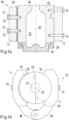
- the blow molding station 10 has a first mold carrier 12 and a second mold carrier 14, which carry parts of a mold 32 for the container to be molded.
- the mold 32 has at least a first mold half 16 and a second mold half 18.
- the mold 32 can have further mold parts, e.g. a base mold 26.
- the first mold half 16 can be firmly connected to the first mold carrier 12 and mounted on it by means of connecting elements 34, in particular screws. This does not, however, rule out the possibility that the first mold half 16 can be movably mounted on the first mold carrier 16.
- the second mold half 18 is mounted on the second mold carrier 14.
- the second mold carrier 14 is pivotably mounted in relation to the first mold carrier 12.
- a joint 36 can connect the first mold carrier 12 to the second mold carrier 14, wherein the joint 36 has a pivot axis 38.
- the second mold carrier 14 and thus also the second mold half 18 can therefore be pivoted about the pivot axis 38 in relation to the first mold carrier 12 or the first mold half 16.
- this does not rule out the possibility that the first mold carrier 12 can also be pivotably designed.
- the mold 32 can be opened and closed by means of a pivoting movement of the second mold carrier 14.
- the blow molding station 10 In the open state, the blow molding station 10 is in a first pivoting position in which a preform can be inserted into the first mold half 16 or a container can be removed from the first mold half 16.
- the blow molding station 10 In the closed state, the blow molding station 10 is in a second pivoting position in which the second mold half 18 rests against the first mold half 16, so that at least part of the shape 32 of the container to be produced is formed. Centering elements 39 can be provided on the two mold halves 16, 18 to center the second mold half 18 on the first mold half 16.
- the bearing of the second mold half 18 is designed such that the second mold half 18 is self-aligning when the blow molding station 10 changes to the second pivot position, e.g. from the first pivot position.
- the second mold half 18 can therefore be automatically aligned when it is placed against the first mold half 16. A pressure pad or a pancake cylinder are no longer required for this.
- the second mold half 18 is mounted on a plain bearing 20 on the second mold carrier 14.
- the second mold half 18 can therefore be moved at least along the central axis 30 of the container to be produced in the axial direction and in the circumferential direction around the central axis 30. In this way, deviations, tolerances and deformations can be compensated.
- the sliding bearing 20 can be designed as a sliding bearing film, which can be fastened to a surface of the second mold carrier 14 facing the second mold half 18.
- the second mold carrier 14 can have connecting elements 24 that are flexible and with which the second mold half 18 can be fastened to the second mold carrier 14.
- the second mold carrier 14 can have ultra bushings 22 in which connecting elements 24 for fastening the second mold half 18 to the second mold carrier 14 can be mounted.
- the connecting elements 24 can be movably mounted in the ultra bushings 22 in relation to the second mold carrier 14.
- the connecting elements 24 can then be designed to be rigid, for example.
- the mold 32 of the blow molding station 10 can also have a ring carrier 28 for the base mold 26.
- the base mold 26 can be mounted in the ring carrier 28 and form the mold 32 for the container to be produced with the two mold halves 16, 18.
- this does not exclude the possibility that the mold 32 can have further molded parts for molding areas of the container to be produced.
- the first mold half 16 is mounted in a self-aligning manner on the first mold half 12, the above explanations regarding the second mold half 18 and the second mold carrier 14 apply analogously to the first mold half 16 and the first mold carrier 12.
- the blow molding station 10 in this example has an elastomer body 40 on which the second mold half 18 is mounted on the second mold carrier 14.
- the elastomer body 40 can be used as a rubber cushion
- the elastomer body 40 can, for example, be vulcanized both to the second mold half 18 and to the second mold carrier 14 and thus fasten the second mold half 18 to the second mold carrier 14.
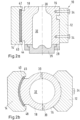
- the second mold carrier 14 can be Figure 2a further have an upper limit 42 and a lower limit 44 for the elastomer body 40. Furthermore, the second mold carrier 14 can according to Figure 2b also have a first lateral boundary 46 and a second lateral boundary 48, which are arranged on opposite sides of the elastomer body 40.
- the elastomer body 40 is further limited by the second mold half 18 and the second mold carrier 14, in particular in the second pivot position. As can be seen from the Figures 2a and 2b As can be seen, the elastomer body 40 is thus limited on almost all sides.
- the material of the elastomer body 40 is positively limited by the limits 42 - 48. Therefore, in the second pivot position, the material of the elastomer body 40 can only deviate from its original shape to a very limited extent, if at all, so that the elastomer body 40 can exhibit behavior like an incompressible hydraulic fluid.
- the second mold half 18 is therefore mounted as if it were floating on an incompressible hydraulic fluid.
- the second mold half can therefore compensate for deviations, tolerances and deformations of the two mold halves 16, 18.
- the elastomer body 40 can be designed, for example, as a rubber cushion.
- the rubber material can have a low hardness of 10 to 100 Shore A, preferably 30 to 60 Shore A.
- FIG. 3 a system 50 for producing containers is shown.
- the system 50 has at least one device 54 for thermal conditioning of preforms, at least one transport device 56 and at least one blow molding machine 52.
- the blow molding machine 52 has a plurality of blow molding stations 10, of which at least one is designed according to the previous description.
- the blow molding stations 10 are arranged along a circumference of a blow molding wheel 64.
- the blow molding stations 10 can be positioned equidistant from one another. By rotating the blow molding wheel 64, the blow molding stations 10 can be transported past the transport device 56 one after the other and alternately change between the first and second pivoting positions depending on the angular position of the blow molding station 10 in question.
- the system 50 can further comprise a feed device 62 for preforms with a feed wheel 60.
- the feed wheel 60 can feed the preforms from the feed device 62 to the device 54, in which the preforms can be thermally conditioned for forming in the blow molding machine 52.
- the transport device 56 can pick up the thermally conditioned preforms from the device 54 and place them in the blow molding stations 10 of the blow molding machines 52 arranged at the transfer position. For this purpose, the blow molding stations 10 are in the first pivot position at the transfer position of the transport device 56. The preforms can then be placed in the first mold half 16.
- the blowing stations 10 are continuously transported in the direction of the arrow by a rotation of the blowing wheel 64 of the blow molding machine 52 and change to the second swivel position. During the change, the self-aligning second mold halves 18 of the blowing stations 10 can automatically compensate for deviations, tolerances and deformations.
- the preforms are formed into containers. This can be done with a blowing gas or with a liquid and takes place during the rotation of the blowing wheel 64.
- blowing stations 10 are returned to the first swivel position and reach a further transfer position by rotating the blowing wheel 64.
- a further transport device 58 can there manufactured containers from the opened blow molding stations 10. The containers can be removed from the first mold half 16.
- the blow molding station 10 can optionally further comprise at least one element not shown in the figures from the following group: a drive for pivoting the second mold carrier 14, a locking mechanism for locking the second mold half 18 on the first mold half 16 in the second pivot position and further components for operating the blow molding station 10.
Landscapes
- Engineering & Computer Science (AREA)
- Manufacturing & Machinery (AREA)
- Mechanical Engineering (AREA)
- Moulds For Moulding Plastics Or The Like (AREA)
- Blow-Moulding Or Thermoforming Of Plastics Or The Like (AREA)
Abstract
Description
- Die Erfindung betrifft eine Blasstation und eine Blasformmaschine umfassend die Blasstation.
- Zur Herstellung von Behältern aus Kunststoff können zum Beispiel Blasformmaschinen verwendet werden, in denen Vorformlinge aus Kunststoff in Blasstationen zu Behältern umgeformt werden. Die Blasstationen weisen dabei Formen für die Umformung der Vorformlinge in die herzustellenden Behälter auf, wobei die Formen mindestens zwei Formhälften aufweisen können. Eine der Formhälften kann zur anderen Formhälfte schwenkbar sein, sodass die Form zum Einlegen eines Vorformlings bzw. zum Entnehmen eines Behälters geöffnet und zum Umformen eines Vorformlings zu einem Behälter geschlossen werden kann. Damit die Formhälften zueinander korrekt positioniert sind, können zum Beispiel Zentrierelemente verwendet werden. Weiter kann das Umformen durch das Einführen eines Fluids in den Vorformling unter einem großen Druck durchgeführt werden, zum Beispiel mit bis zu 40 bar Druckluft.
- Um das Auseinanderdrücken der Formhälften zu vermeiden, ist aus
DE 20 2004 011 785 U1 bekannt, eine Formhälfte auf einem Druckkissen zu lagern, das diese Formhälfte während des Beaufschlagens des Vorformlings mit Druckluft gegen die andere Formhälfte drückt. Weiter können damit Toleranzen, Abweichungen und Verformungen zwischen den Formhälfte ausgeglichen werden. - Aufgabe der Erfindung ist es, eine Blasstation und eine Blasformmaschine bereitzustellen, die einfacher aufgebaut sind und weiter einen Ausgleich für Abweichungen, Toleranzen und Verformungen zwischen den Formhälften bereitstellen.
- Die Aufgabe wird durch die Merkmale der unabhängigen Ansprüche gelöst. Vorteilhafte Weiterbildungen sind Gegenstand der abhängigen Ansprüche sowie der folgenden Beschreibung.
- Bei einer Blasstation zum Umformen eines Vorformlings zu einem Behälter für eine Blasformmaschine zum Herstellen von Kunststoff-Behältern, umfassend einen ersten Formträger, einen zweiten Formträger, einer an dem ersten Formträger gelagerten ersten Formhälfte und einer an dem zweiten Formträger gelagerten zweiten Formhälfte, wobei der zumindest eine der Formträger schwenkbar gelagert ist und die Blasstation in einer ersten Schwenkposition des schwenkbar gelagerten Formträgers zum Einlegen eines Vorformlings in eine der Formhälften oder zum Entnehmen eines Behälters aus einer der Formhälften geöffnet ist und in einer zweiten Schwenkposition des schwenkbar gelagerten Formträgers, in der die zweite Formhälfte und die erste Formhälfte aneinander anliegen, geschlossen ist, ist erfindungsgemäß vorgesehen, dass zumindest eine der Formhälften für den Wechsel in die zweite Schwenkposition bezüglich der jeweils anderen Formhälfte selbstausrichtend gelagert ist..
- Die Erfindung stellt damit eine Blasstation bereit, bei der eine Selbstausrichtung zumindest einer Formhälfte beim Wechsel in die zweite Schwenkposition stattfindet. Eine aktive Ausrichtung der selbstausrichtend gelagerten Formhälfte mittels beispielsweise eines Druckkissens ist nicht weiter erforderlich. Wenn z. B. die zweite Formhälfte selbstausrichtend an dem zweiten Formträger gelagert ist, kann sie dazu derart an dem zweiten Formträger gelagert sein, dass beim Wechsel in die zweite Schwenkposition, z. B. aus der ersten Schwenkposition, eine Selbstausrichtung der zweiten Formhälfte in Bezug zur ersten Formhälfte stattfindet. Dabei wirkt die erste Formhälfte, die beispielsweise fest an dem ersten Formträger angebracht sein kann, als Bezugspunkt für die Ausrichtung der zweiten Formhälfte. Eine aktive Ausrichtung, zum Beispiel mittels eines Druckkissens ist nicht weiter erforderlich. Die Selbstausrichtung der zweiten Formhälfte erfolgt passiv und damit automatisch beim Wechsel in die zweite Schwenkposition. Durch das Selbstausrichten der selbstausrichtend gelagerten Formhälfte können Toleranzen, Abweichungen und Verformungen zwischen den beiden Formhälften ausgeglichen werden. Nähte an den hergestellten Behältern werden damit vermieden. Damit kann die Qualität der hergestellten Behälter erhöht werden. Weiter sinkt dadurch die Belastung auf Zentrierelemente, die eine Zentrierung der beiden Formhälften gegeneinander bewirken, sodass der Verschleiß dieser Zentrierelemente verringert wird.
- In einem Beispiel kann alternativ oder zusätzlich auch die erste Formhälfte selbstausrichtend an dem ersten Formträger gelagert sein. Die oben angeführten Erläuterungen gelten dann analog für die erste Formhälfte.
- Gemäß einem Beispiel kann die Blasstation druckkissenlos und/oder pancakezylinderlos ausgebildet sein.
- Durch das Weglassen des Druckkissens bzw. des Pancake-Zylinders vereinfacht sich der Aufbau der Blasstation und wird kostengünstiger. Aufgrund der automatisch erfolgenden Ausrichtung der selbstausrichtend gelagerten Formhälfte können dennoch Behälter mit verbesserter Qualität hergestellt werden.
- Weiter ist beispielsweise denkbar, dass der Formträger, an dem die selbstausrichtend gelagerte Formhälfte gelagert ist, ein Gleitlager für die selbstausrichtend gelagerte Formhälfte aufweisen kann ist.
- An dem Gleitlager kann die selbstausrichtend gelagerte Formhälfte an diesem Formträger gelagert sein. Wenn z. B. die zweite Formhälfte die selbstausrichtend gelagerte Formhälfte ist, kann sie auf dem Gleitlager gleiten und sich relativ zur ersten Formhälfte drehen und sich auf diese Weise beim Wechsel in die zweite Schwenkposition selbst ausrichten. Die Drehachse für die relative Drehung kann dazu zwischen der ersten Formhälfte und der zweiten Formhälfte angeordnet sein, wenn die zweite Formhälfte in der zweiten Schwenkposition ist, d. h. wenn die Form bzw. die Blasstation geschlossen ist. Das Gleitlager kann flexibel an der zweiten Formhälfte angeordnet sein. So kann das Gleitlager zum Beispiel radial beabstandet zu einer Zentralachse der Form zwischen der zweiten Formhälfte und dem zweiten Formträger angeordnet sein. Alternativ oder zusätzlich kann das Gleitlager auch in axialer Richtung zwischen der zweiten Formhälfte und dem zweiten Formträger angeordnet sein.
- Gemäß einem weiteren Beispiel kann das Gleitlager eine Gleitlagerfolie aufweisen.
- Mit einer Gleitlagerfolie kann auf einfache und kostengünstige Weise ein Gleitlager für die zweite Formhälfte bereitgestellt werden.
- In einem weiteren Beispiel kann die selbstausrichtend gelagerte Formhälfte mit flexiblen Verbindungselementen, insbesondere einer Ultrabuchse, an dem Formträger befestigt sein, an dem sie gelagert ist.
- Mit den flexiblen Verbindungselementen wird damit eine Verbindung zwischen dem die selbstausrichtend gelagerte Formhälfte tragenden Formträger und der Formhälfte bereitgestellt, die ein Gleiten und Drehen der selbstausrichtend gelagerten Formhälfte relativ zum Formträger, an dem sie gelagert ist, und relativ zur anderen Formhälfte erlaubt.
- Die selbstausrichtend gelagerte Formhälfte kann zum Beispiel mit federnden Verbindungselementen an dem Formträger befestigt sein, an dem sie gelagert ist.
- Die federnden Verbindungselemente können alternativ oder zusätzlich zu den flexiblen Verbindungselementen vorgesehen werden. Auch mit den federnden Verbindungselementen wird eine Verbindung zwischen dem Formträger, an dem die selbstausrichtend gelagerte Formhälfte gelagert ist und der selbstausrichtend gelagerten Formhälfte bereitgestellt, die ein Gleiten und Drehen der selbstausrichtend gelagerten Formhälfte relativ zum Formträger und relativ zur anderen Formhälfte erlaubt.
- Es ist weiter denkbar, dass der Formträger, an dem die selbstausrichtend gelagerte Formhälfte gelagert ist, einen Elastomerkörper, insbesondere ein Gummikissen, aufweisen kann, an dem die selbstausrichtend gelagerte Formhälfte gelagert ist.
- Der Elastomerkörper kann die selbstausrichtend gelagerte Formhälfte an dem Formträger befestigen. Durch die Elastizität des Elastomerkörpers kann die selbstausrichtend gelagerte Formhälfte relativ zum Formträger bewegt werden. Dabei kann die auf dem Elastomerkörper selbstausrichtend gelagerte Formhälfte sowohl eine Scherbewegung als auch eine Schwenkbewegung zum Formträger durchführen, an dem sie gelagert ist. Wenn der Elastomerkörper als Gummikissen ausgebildet ist, weist das Gummi vorzugsweise eine geringe Härte auf. Weiter kann der Elastomerkörper bzw. das Gummikissen beispielsweise an die selbstausrichtend gelagerte Formhälfte und dem Formträger anvulkanisiert sein.
- Gemäß einem weiteren Beispiel kann der Elastomerkörper zum größten Teil allseitig begrenzt sein.
- Der Elastomerkörper kann sich in diesem Beispiel nicht über die Begrenzungen ausdehnen, sodass das Verhalten des Elastomerkörpers mit der Ausdehnung der Begrenzungen um den Elastomerkörper eingestellt werden kann.
- Weiter kann der Elastomerkörper beispielsweise derart ausgebildet sein, dass er ein Verhalten wie eine inkompressible hydraulische Flüssigkeit aufweist.
- Durch dieses Verhalten kann der Formträger, an dem die selbstausrichtend gelagerte Formhälfte gelagert ist, weiter einen Druck auf die selbstausrichtend gelagerte Formhälfte ausüben, um die selbstausrichtend gelagerte Formhälfte in der zweiten Schwenkposition auf die andere Formhälfte zu drücken. Gleichzeitig ermöglicht der Elastomerkörper weiter eine automatische Ausrichtung der selbstausrichtend gelagerten Formhälfte beim Wechsel in die zweite Schwenkposition. Dieses Verhalten kann beispielsweise mittels der oben erläuterten Begrenzung eingestellt werden.
- Weiter betrifft die Erfindung eine Blasformmaschine zum Herstellen von Kunststoff-Behältern umfassend ein Blasrad und eine Vielzahl von Blasstationen nach der vorangegangenen Beschreibung, wobei die Blasstationen an dem Umfang eines Blasrades, vorzugsweise äquidistant, verteilt angeordnet sind.
- Vorteile und Wirkungen sowie Weiterbildungen der Blasformmaschine ergeben sich aus den Vorteilen und Wirkungen sowie Weiterbildungen der oben beschriebenen Blasstation. Zur Vermeidung von Wiederholungen wird daher in dieser Hinsicht auf die vorangegangene Beschreibung verwiesen.
- Die Erfindung betrifft weiter eine Anlage zum Herstellen von Behältern, die zumindest eine Vorrichtung zur thermischen Konditionierung der Vorformlinge, zumindest eine Transportvorrichtung und zumindest eine Blasformmaschine gemäß der oben angeführten Beschreibung aufweist, wobei die Transportvorrichtung die thermisch konditionieren Vorformlinge aus der Vorrichtung entnimmt und der Blasformmaschine zuführt.
- Im Folgenden wird die Erfindung anhand beispielhafter Ausführungsformen mittels der beigefügten Zeichnung beschrieben. Es zeigen:
- Figur 1a, b
- eine schematische Darstellung einer Blasstation gemäß einem ersten Beispiel im Längsschnitt (a) und in der Draufsicht (b);
- Figur 2a, b
- eine schematische Darstellung einer Blasstation gemäß einem zweiten Beispiel im Längsschnitt (a) und im Querschnitt (b); und
- Figur 3
- eine schematische Darstellung einer Anlage zum Herstellen von Behältern.
- Die Blasstation zum Umformen eines Vorformlings zu einem Behälter für eine Blasmaschine zum Herstellen von Kunststoff-Behältern wird im Folgenden in ihrer Gesamtheit mit dem Bezugszeichen 10 bezeichnet.
- Wie in
Figur 1a dargestellt weist die Blasstation 10 einen ersten Formträger 12 und einen zweiten Formträger 14 auf, die Teile einer Form 32 für den zu formenden Behälter tragen. Die Form 32 weist mindestens eine erste Formhälfte 16 und eine zweite Formhälfte 18 auf. Die Form 32 kann weiter Formteile, z. B. eine Bodenform 26, aufweisen. Die erste Formhälfte 16 kann mittels Verbindungselementen 34, insbesondere Schrauben, fest mit dem ersten Formträger 12 verbunden und an diesem gelagert sein. Damit sei jedoch nicht ausgeschlossen, dass die erste Formhälfte 16 beweglich an dem ersten Formträger 16 gelagert sein kann. Die zweite Formhälfte 18 ist an dem zweiten Formträger 14 gelagert. - Wie in
Figur 1b dargestellt, ist der zweite Formträger 14 schwenkbar in Bezug auf den ersten Formträger 12 gelagert. Dazu kann ein Gelenk 36 den ersten Formträger 12 mit den zweiten Formträger 14 verbinden, wobei das Gelenk 36 eine Schwenkachse 38 aufweist. Der zweite Formträger 14 und damit auch die zweite Formhälfte 18 können daher in Bezug auf dem ersten Formträger 12 bzw. die erste Formhälfte 16 um die Schwenkachse 38 geschwenkt werden. Damit sei jedoch nicht ausgeschlossen, dass auch der erste Formträger 12 schwenkbar ausgebildet sein kann. - Die Form 32 kann in diesem Beispiel mittels einer Schwenkbewegung des zweiten Formträgers 14 geöffnet und geschlossen werden. Im geöffneten Zustand ist die Blasstation 10 in einer ersten Schwenkposition, in der ein Vorformling in die erste Formhälfte 16 eingelegt werden kann oder ein Behälter aus der ersten Formhälfte 16 entnommen werden kann.
- Im geschlossenen Zustand ist die Blasstation 10 in einer zweiten Schwenkposition, in der die zweite Formhälfte 18 an der ersten Formhälfte 16 anliegt, sodass zumindest ein Teil der Form 32 des herzustellenden Behälters gebildet wird. Für eine Zentrierung der zweiten Formhälfte 18 an der ersten Formhälfte 16 können Zentrierelemente 39 an den beiden Formhälften 16, 18 vorgesehen werden.
- Die Lagerung der zweiten Formhälfte 18 ist derart ausgebildet, dass die zweite Formhälfte 18 selbstausrichtend ist, wenn die Blasstation 10 in die zweite Schwenkposition, z. B. aus der ersten Schwenkposition, wechselt. Die zweite Formhälfte 18 kann daher beim Anlegen an die erste Formhälfte 16 automatisch ausgerichtet werden. Ein Druckkissen oder ein Pancake-Zylinder sind dazu nicht weiter erforderlich.
- In dem Beispiel gemäß der
Figuren 1a und 1b ist die zweite Formhälfte 18 auf einem Gleitlager 20 an dem zweiten Formträger 14 gelagert. Die zweite Formhälfte 18 kann daher zumindest entlang der Zentralachse 30 des herzustellenden Behälters in axialer Richtung und in Umfangsrichtung um die Zentralachse 30 bewegt werden. Auf diese Weise können Abweichungen, Toleranzen und Verformungen ausgeglichen werden. - Das Gleitlager 20 kann als eine Gleitlagerfolie ausgebildet sein, die auf einer zur zweiten Formhälfte 18 weisenden Fläche des zweiten Formträgers 14 befestigt sein kann.
- Weiter kann der zweite Formträger 14 Verbindungselemente 24 aufweisen, die flexibel sind und mit denen die zweite Formhälfte 18 an dem zweiten Formträger 14 befestigt sein kann. Alternativ oder zusätzlich kann der zweite Formträger 14 Ultrabuchsen 22 aufweisen, in denen Verbindungselemente 24 zum Befestigen der zweiten Formhälfte 18 an dem zweiten Formträger 14 gelagert sein können. Die Verbindungselemente 24 können in den Ultrabuchsen 22 in Bezug zum zweiten Formträger 14 beweglich gelagert sein. Dann können die Verbindungselemente 24 beispielsweise starr ausgebildet sein.
- Die Form 32 der Blasstation 10 kann weiter einen Ringträger 28 für die Bodenform 26 aufweisen. Die Bodenform 26 kann im Ringträger 28 gelagert sein und mit den beiden Formhälften 16, 18 die Form 32 für den herzustellenden Behälter bilden. Damit sei jedoch nicht ausgeschlossen, dass die Form 32 weitere Formteile zum Formen von Bereichen des herzustellenden Behälters aufweisen kann.
- Falls alternativ oder zusätzlich die erste Formhälfte 16 selbstausrichtend an der ersten Formhälfte 12 gelagert ist, gelten die obigen Erläuterungen zu der zweiten Formhälfte 18 und dem zweiten Formträger 14 analog für die erste Formhälfte 16 und den ersten Formträger 12.
- In den
Figuren 2a und 2b ist ein alternatives Beispiel der Erfindung dargestellt. Elemente, die in dem Beispiel nach denFiguren 1a und 1b bereits beschrieben wurden, weisen in denFiguren 2a und 2b die gleichen Bezugsziffern auf. Der Schwenkmechanismus 36, 38 ausFigur 1a und 1b ist in diesem Beispiel weggelassen, kann jedoch selbstverständlich ebenfalls vorgesehen werden. - Anstelle des Gleitlagers 20 aus
Figur 1a und 1b , weist die Blasstation 10 in diesem Beispiel einen Elastomerkörper 40 auf, auf dem die zweite Formhälfte 18 an dem zweiten Formträger 14 gelagert ist. Der Elastomerkörper 40 kann als Gummikissen ausgebildet sein. Weiter kann der Elastomerkörper 40 zum Beispiel sowohl an die zweite Formhälfte 18 als auch an den zweiten Formträger 14 anvulkanisiert sein und damit zweite Formhälfte 18 an dem zweiten Formträger 14 befestigen. - Der zweite Formträger 14 kann gemäß
Figur 2a weiter eine obere Begrenzung 42 und eine untere Begrenzung 44 für den Elastomerkörper 40 aufweisen. Weiter kann der zweite Formträger 14 gemäßFigur 2b auch eine erste seitliche Begrenzung 46 und eine zweite seitliche Begrenzung 48 aufweisen, die an gegenüberliegenden Seiten des Elastomerkörpers 40 angeordnet sind. Der Elastomerkörper 40 wird insbesondere in der zweiten Schwenkposition weiter durch die zweite Formhälfte 18 und den zweiten Formträger 14 begrenzt. Wie aus denFiguren 2a und 2b ersichtlich, ist der Elastomerkörper 40 damit nahezu allseitig begrenzt. - Bei elastischen Bewegungen des Elastomerkörpers 40 wird das Material des Elastomerkörpers 40 durch die Begrenzungen 42 - 48 formschlüssige begrenzt. Daher kann das Material des Elastomerkörpers 40 in der zweiten Schwenkposition, wenn überhaupt, lediglich in sehr begrenztem Maß aus seiner ursprünglichen Gestalt ausweichen, sodass der Elastomerkörper 40 ein Verhalten wie eine inkompressible hydraulische Flüssigkeit aufweisen kann.
- Die zweite Formhälfte 18 ist in diesem Beispiel daher derart gelagert, als ob sie auf einer inkompressiblen hydraulischen Flüssigkeit schwimmen würde. Beim Wechsel in die zweite Schwenkposition kann die zweite Formhälfte daher Abweichungen, Toleranzen und Verformungen der beiden Formhälften 16, 18 ausgleichen.
- Der Elastomerkörper 40 kann beispielsweise als Gummikissen ausgebildet sein. Das Gummimaterial kann eine geringe Härte von 10 bis 100 Shore A, bevorzugt 30 bis 60 Shore A, aufweisen.
- In
Figur 3 ist eine Anlage 50 zum Herstellen von Behältern dargestellt. Die Anlage 50 weist zumindest eine Vorrichtung 54 zur thermischen Konditionierung von Vorformlingen, zumindest eine Transportvorrichtung 56 und zumindest eine Blasformmaschine 52 auf. - Die Blasformmaschine 52 weist eine Vielzahl von Blasstationen 10 auf, von denen mindestens eine gemäß der vorangegangenen Beschreibung ausgebildet ist. Die Blasstationen 10 sind entlang eines Umfangs eines Blasrads 64 angeordnet. Dabei können die Blasstationen 10 äquidistant zueinander positioniert sein. Durch eine Drehung des Blasrads 64 können die Blasstationen 10 nacheinander an der Transportvorrichtung 56 vorbeitransportiert werden und wechseln nacheinander abwechselnd je nach Winkelstellung der betreffenden Blasstation 10 zwischen der ersten und zweiten Schwenkposition.
- Die Anlage 50 kann weiter eine Zufuhrvorrichtung 62 für Vorformlinge mit einem Zufuhrrad 60 aufweisen. Das Zufuhrrad 60 kann die Vorformlinge aus der Zufuhrvorrichtung 62 der Vorrichtung 54 zuführen, in der die Vorformlinge für das Umformen in der Blasformmaschine 52 thermisch konditioniert werden können. Die Transportvorrichtung 56 kann die thermisch konditionierten Vorformlinge aus der Vorrichtung 54 aufnehmen und in die an der Übergabeposition angeordneten Blasstationen 10 der Blasformmaschinen 52 einlegen. Dazu sind die Blasstationen 10 an der Übergabeposition der Transportvorrichtung 56 in der ersten Schwenkposition. Die Vorformlinge können dann in die erste Formhälfte 16 eingelegt werden.
- Die Blasstationen 10 werden durch eine Drehung des Blasrads 64 der Blasformmaschine 52 kontinuierlich in Pfeilrichtung transportiert und wechseln dabei in die zweite Schwenkposition. Bei dem Wechsel können die selbstausrichtend gelagerten zweiten Formhälften 18 der Blasstationen 10 automatisch Abweichungen, Toleranzen und Verformungen ausgleichen.
- Wenn die Blasstationen 10 in der zweiten Schwenkposition sind, werden die Vorformlinge zu Behältern umgeformt. Dies kann mit einem Blasgas oder mit einer Flüssigkeit durchgeführt werden und erfolgt während der Drehung des Blasrads 64.
- Nach dem Formen der Behälter werden die Blasstationen 10 wieder in die erste Schwenkposition überführt und gelange durch die Drehung des Blasrads 64 an eine weitere Übergabeposition. Eine weitere Transportvorrichtung 58 kann dort die hergestellten Behälter aus den geöffneten Blasstationen 10 entnehmen. Die Behälter können dazu aus der ersten Formhälfte 16 entnommen werden.
- Die Blasstation 10 kann optional in allen hier erläuterten beispielhaften Ausführungsformen weiter mindestens ein in den Figuren nicht dargestelltes Element aus der folgenden Gruppe aufweisen: einen Antrieb zum Schwenken des zweiten Formträgers 14, einen Verschlussmechanismus zum Arretieren der zweiten Formhälfte 18 an der ersten Formhälfte 16 in der zweiten Schwenkposition sowie weitere Komponenten für den Betrieb der Blasstation 10 aufweisen.
- Das oben beschriebene Beispiel dient in keiner Weise einer Beschränkung der Erfindung. Vielmehr kann die Erfindung in vielfältiger Weise abgewandelt werden. Alle oben beschriebenen Merkmale der Erfindung können allein oder in Kombination miteinander wesentlich für die Erfindung sein.
-
- 10
- Blasstation
- 12
- erster Formträger
- 14
- zweiter Formträger
- 16
- erste Formhälfte
- 18
- zweite Formhälfte
- 20
- Gleitlager
- 22
- Ultrabuchse
- 24
- Verbindungselement
- 26
- Bodenform
- 28
- Ringträger
- 30
- Zentralachse
- 32
- Form
- 34
- Verbindungselement
- 36
- Gelenk
- 38
- Schwenkachse
- 39
- Zentrierelement
- 40
- Elastomerkörper
- 42
- obere Begrenzung
- 44
- untere Begrenzung
- 46
- erste seitliche Begrenzung
- 48
- zweite seitliche Begrenzung
- 50
- Anlage
- 52
- Blasformmaschine
- 54
- Vorrichtung zur thermischen Konditionierung von Vorformlingen
- 56
- Transportvorrichtung
- 58
- Transportvorrichtung
- 60
- Zufuhrrad
- 62
- Zufuhrvorrichtung
- 64
- Blasrad
Claims (11)
- Blasstation (10) zum Umformen eines Vorformlings zu einem Behälter für eine Blasformmaschine (52) zum Herstellen von Kunststoff-Behältern, umfassend einen ersten Formträger (12), einen zweiten Formträger (14), einer an dem ersten Formträger (12) gelagerten ersten Formhälfte (16) und einer an dem zweiten Formträger (14) gelagerten zweiten Formhälfte (18), wobei der zumindest einer der Formträger (12, 14) schwenkbar gelagert ist und die Blasstation (10) in einer ersten Schwenkposition des schwenkbar gelagerten Formträgers (12, 14) zum Einlegen eines Vorformlings in eine der Formhälften (16, 18) oder zum Entnehmen eines Behälters aus einer der Formhälften (16, 18) geöffnet ist und in einer zweiten Schwenkposition des schwenkbar gelagerten Formträgers (12, 14), in der die zweite Formhälfte (18) und die erste Formhälfte (16) aneinander anliegen, geschlossen ist, dadurch gekennzeichnet, dass zumindest eine der Formhälften (16, 18) für den Wechsel in die zweite Schwenkposition bezüglich der jeweils anderen Formhälfte (16, 18) selbstausrichtend gelagert ist.
- Blasstation (10) nach Anspruch 1, dadurch gekennzeichnet, dass die Blasstation (10) druckkissenlos und/oder pancakezylinderlos ausgebildet ist.
- Blasstation (10) nach einem der Ansprüche 1 oder 2, dadurch gekennzeichnet, dass der Formträger (12, 14), an dem die selbstausrichtend gelagerte Formhälfte gelagert ist, ein Gleitlager (20) für die selbstausrichtend gelagerte Formhälfte (16, 18) aufweist.
- Blasstation (10) nach Anspruch 3, dadurch gekennzeichnet, dass das Gleitlager (20) eine Gleitlagerfolie aufweist.
- Blasstation (10) nach Anspruch 3 oder 4, dadurch gekennzeichnet, dass die selbstausrichtend gelagerte Formhälfte (16, 18) mit flexiblen Verbindungselementen (22), insbesondere einer Ultrabuchse, an dem Formträger (12, 14) befestigt ist, an dem sie gelagert ist.
- Blasstation (10) nach einem der Ansprüche 3 bis 5, dadurch gekennzeichnet, dass die selbstausrichtend gelagerte Formhälfte (16, 18) mit federnden Verbindungselementen (24) an dem Formträger (12, 14) befestigt ist, an dem sie gelagert ist.
- Blasstation (10) nach Anspruch 1 oder 2, dadurch gekennzeichnet, dass der Formträger (12, 14), an dem die selbstausrichtend gelagerte Formhälfte (16, 18) gelagert ist, einen Elastomerkörper (40), insbesondere ein Gummikissen, aufweist, an dem die selbstausrichtend gelagerte Formhälfte (16, 18) gelagert ist.
- Blasstation (10) nach Anspruch 7, dadurch gekennzeichnet, dass der Elastomerkörper (40) zum größten Teil allseitig begrenzt ist.
- Blasstation (10) nach Anspruch 7 oder 8, dadurch gekennzeichnet, dass der Elastomerkörper (40) derart ausgebildet ist, dass er ein Verhalten wie eine inkompressible hydraulische Flüssigkeit aufweist.
- Blasformmaschine (52) zum Herstellen von Kunststoff-Behältern umfassend ein Blasrad und eine Vielzahl von Blasstationen (10) nach einem der vorangegangenen Ansprüche, wobei die Blasstationen (10) an dem Umfang eines Blasrades (64), vorzugsweise äquidistant, verteilt angeordnet sind.
- Anlage zum Herstellen von Behältern, die zumindest eine Vorrichtung (54) zur thermischen Konditionierung der Vorformlinge, zumindest eine Transportvorrichtung (56) und zumindest eine Blasformmaschine (52) nach Anspruch 10 aufweist, wobei die Transportvorrichtung (56) die thermisch konditionieren Vorformlinge aus der Vorrichtung (54) entnimmt und der Blasformmaschine (52) zuführt.
Applications Claiming Priority (1)
| Application Number | Priority Date | Filing Date | Title |
|---|---|---|---|
| DE102023108104.7A DE102023108104A1 (de) | 2023-03-30 | 2023-03-30 | Blasstation und Blasformmaschine umfassend die Blasstation |
Publications (2)
| Publication Number | Publication Date |
|---|---|
| EP4438265A1 true EP4438265A1 (de) | 2024-10-02 |
| EP4438265B1 EP4438265B1 (de) | 2025-12-10 |
Family
ID=90363748
Family Applications (1)
| Application Number | Title | Priority Date | Filing Date |
|---|---|---|---|
| EP24161935.2A Active EP4438265B1 (de) | 2023-03-30 | 2024-03-07 | Blasstation und blasformmaschine umfassend die blasstation |
Country Status (2)
| Country | Link |
|---|---|
| EP (1) | EP4438265B1 (de) |
| DE (1) | DE102023108104A1 (de) |
Citations (6)
| Publication number | Priority date | Publication date | Assignee | Title |
|---|---|---|---|---|
| DE4212584A1 (de) * | 1992-04-15 | 1993-10-21 | Krupp Corpoplast Masch | Vorspanneinrichtung |
| US6729868B1 (en) * | 1999-06-25 | 2004-05-04 | Klaus Vogel | Device for blow moulding containers |
| DE202004011785U1 (de) | 2004-07-27 | 2004-10-14 | Krones Ag | Blasformbehälter und Formblasmaschine |
| US20110052747A1 (en) * | 2009-09-02 | 2011-03-03 | Krones Ag | Apparatus for the shaping of plastics-material containers with a blow mould |
| EP2554357A1 (de) * | 2011-08-05 | 2013-02-06 | Gea Procomac S.p.A. | Blasformmaschine mit Formhalteeinrichtung und entsprechendes Verfahren |
| DE102014019722A1 (de) * | 2014-05-28 | 2015-12-03 | Krones Ag | Blasformeinrichtung mit vorspannbarer Befestigung für Blasformen |
-
2023
- 2023-03-30 DE DE102023108104.7A patent/DE102023108104A1/de active Pending
-
2024
- 2024-03-07 EP EP24161935.2A patent/EP4438265B1/de active Active
Patent Citations (6)
| Publication number | Priority date | Publication date | Assignee | Title |
|---|---|---|---|---|
| DE4212584A1 (de) * | 1992-04-15 | 1993-10-21 | Krupp Corpoplast Masch | Vorspanneinrichtung |
| US6729868B1 (en) * | 1999-06-25 | 2004-05-04 | Klaus Vogel | Device for blow moulding containers |
| DE202004011785U1 (de) | 2004-07-27 | 2004-10-14 | Krones Ag | Blasformbehälter und Formblasmaschine |
| US20110052747A1 (en) * | 2009-09-02 | 2011-03-03 | Krones Ag | Apparatus for the shaping of plastics-material containers with a blow mould |
| EP2554357A1 (de) * | 2011-08-05 | 2013-02-06 | Gea Procomac S.p.A. | Blasformmaschine mit Formhalteeinrichtung und entsprechendes Verfahren |
| DE102014019722A1 (de) * | 2014-05-28 | 2015-12-03 | Krones Ag | Blasformeinrichtung mit vorspannbarer Befestigung für Blasformen |
Also Published As
| Publication number | Publication date |
|---|---|
| EP4438265B1 (de) | 2025-12-10 |
| DE102023108104A1 (de) | 2024-10-02 |
Similar Documents
| Publication | Publication Date | Title |
|---|---|---|
| EP0881071A2 (de) | Druckmaschine | |
| EP1312459A2 (de) | Vorrichtung zur Blasformung von Behältern | |
| EP3294525B1 (de) | Umformungsstation für blasformmaschinen ohne druckkissen | |
| DE102018217776A1 (de) | Teilungswechselstern zum Transportieren und Übergeben von Behältern | |
| DE69503657T2 (de) | Haltevorrichtung für vorformlinge | |
| DE2338587A1 (de) | Halte- und uebergabevorrichtung fuer unvulkanisierte reifen | |
| DE2166908C3 (de) | Kunststoffwarmverformungsmaschine zum Tiefziehen von einseitig offenen Hohlkörpern | |
| DE1596581A1 (de) | Glasformmaschine | |
| DE202016101701U1 (de) | Umformungsstation für Blasformmaschinen ohne Druckkissen | |
| DE2144507C2 (de) | Gelenklager | |
| EP4438265B1 (de) | Blasstation und blasformmaschine umfassend die blasstation | |
| EP1337388A1 (de) | Vorrichtung zur automatischen und gleichzeitigen kompensation eines winkelfehlers und eines achsversatzes bei einer schliesseinheit einer spritzgiessmaschine | |
| EP0320588A2 (de) | Vulkanisierform für eine Reifenvulkanisiermaschine | |
| WO2002032648A2 (de) | Vorrichtung zur kompensation von verkantungen bei formschliesseinheiten von spritzgiessmaschinen | |
| EP2777912B1 (de) | Vorrichtung zum Behandeln von Behältnissen mit Kunststoffführungsrollen aus Polyamidimid | |
| WO2018206633A1 (de) | Drehlager für eine achsbaugruppe eines schwerlastfahrzeugs, achsbaugruppe mit einem derartigen drehlager und schwerlastfahrzeug mit wenigstens einer derartigen achsbaugruppe | |
| DE19732337A1 (de) | Holmlose Spritzgießmaschine | |
| EP1177100A1 (de) | Dehnschicht aus kompressiblem material | |
| DE60016509T2 (de) | Betätigungssystem mit einem elastischen verstellring für eine schwenkbare schubdüse | |
| DE3534937A1 (de) | Spritzgiessform fuer kunststoff-spritzgiessmaschine mit verriegelungseinrichtung | |
| DE4433991C2 (de) | Spreizwerkzeug zur Herstellung hinterschnittener Werkstücke | |
| WO2001026905A1 (de) | Lager für das rundsieb bei rotationssiebdruckwerken | |
| DE10313661B4 (de) | Kreuzgelenk und Verfahren zur Montage desselben | |
| EP4299280B1 (de) | Vorrichtung und verfahren zum umformen von kunststoffvorformlingen zu kunststoffbehältnissen | |
| DE2205907A1 (de) | Hydraulische Extrusionspresse und Verfahren zu ihrem Betrieb |
Legal Events
| Date | Code | Title | Description |
|---|---|---|---|
| PUAI | Public reference made under article 153(3) epc to a published international application that has entered the european phase |
Free format text: ORIGINAL CODE: 0009012 |
|
| STAA | Information on the status of an ep patent application or granted ep patent |
Free format text: STATUS: THE APPLICATION HAS BEEN PUBLISHED |
|
| AK | Designated contracting states |
Kind code of ref document: A1 Designated state(s): AL AT BE BG CH CY CZ DE DK EE ES FI FR GB GR HR HU IE IS IT LI LT LU LV MC ME MK MT NL NO PL PT RO RS SE SI SK SM TR |
|
| STAA | Information on the status of an ep patent application or granted ep patent |
Free format text: STATUS: REQUEST FOR EXAMINATION WAS MADE |
|
| 17P | Request for examination filed |
Effective date: 20250402 |
|
| GRAP | Despatch of communication of intention to grant a patent |
Free format text: ORIGINAL CODE: EPIDOSNIGR1 |
|
| STAA | Information on the status of an ep patent application or granted ep patent |
Free format text: STATUS: GRANT OF PATENT IS INTENDED |
|
| RIC1 | Information provided on ipc code assigned before grant |
Ipc: B29C 49/48 20060101AFI20250812BHEP Ipc: B29C 49/06 20060101ALN20250812BHEP Ipc: B29C 49/36 20060101ALN20250812BHEP Ipc: B29K 67/00 20060101ALN20250812BHEP Ipc: B29L 31/00 20060101ALN20250812BHEP |
|
| INTG | Intention to grant announced |
Effective date: 20250826 |
|
| GRAS | Grant fee paid |
Free format text: ORIGINAL CODE: EPIDOSNIGR3 |
|
| GRAA | (expected) grant |
Free format text: ORIGINAL CODE: 0009210 |
|
| STAA | Information on the status of an ep patent application or granted ep patent |
Free format text: STATUS: THE PATENT HAS BEEN GRANTED |
|
| AK | Designated contracting states |
Kind code of ref document: B1 Designated state(s): AL AT BE BG CH CY CZ DE DK EE ES FI FR GB GR HR HU IE IS IT LI LT LU LV MC ME MK MT NL NO PL PT RO RS SE SI SK SM TR |
|
| REG | Reference to a national code |
Ref country code: CH Ref legal event code: F10 Free format text: ST27 STATUS EVENT CODE: U-0-0-F10-F00 (AS PROVIDED BY THE NATIONAL OFFICE) Effective date: 20251210 Ref country code: GB Ref legal event code: FG4D Free format text: NOT ENGLISH |
|
| REG | Reference to a national code |
Ref country code: DE Ref legal event code: R096 Ref document number: 502024000472 Country of ref document: DE |
|
| REG | Reference to a national code |
Ref country code: IE Ref legal event code: FG4D Free format text: LANGUAGE OF EP DOCUMENT: GERMAN |
|
| P01 | Opt-out of the competence of the unified patent court (upc) registered |
Free format text: CASE NUMBER: UPC_APP_0014560_4438265/2025 Effective date: 20251125 |
|
| PG25 | Lapsed in a contracting state [announced via postgrant information from national office to epo] |
Ref country code: ES Free format text: LAPSE BECAUSE OF FAILURE TO SUBMIT A TRANSLATION OF THE DESCRIPTION OR TO PAY THE FEE WITHIN THE PRESCRIBED TIME-LIMIT Effective date: 20251210 |
|
| REG | Reference to a national code |
Ref country code: LT Ref legal event code: MG9D |
|
| PG25 | Lapsed in a contracting state [announced via postgrant information from national office to epo] |
Ref country code: NO Free format text: LAPSE BECAUSE OF FAILURE TO SUBMIT A TRANSLATION OF THE DESCRIPTION OR TO PAY THE FEE WITHIN THE PRESCRIBED TIME-LIMIT Effective date: 20260310 |
|
| PGFP | Annual fee paid to national office [announced via postgrant information from national office to epo] |
Ref country code: DE Payment date: 20260319 Year of fee payment: 3 |
|
| PG25 | Lapsed in a contracting state [announced via postgrant information from national office to epo] |
Ref country code: HR Free format text: LAPSE BECAUSE OF FAILURE TO SUBMIT A TRANSLATION OF THE DESCRIPTION OR TO PAY THE FEE WITHIN THE PRESCRIBED TIME-LIMIT Effective date: 20251210 Ref country code: FI Free format text: LAPSE BECAUSE OF FAILURE TO SUBMIT A TRANSLATION OF THE DESCRIPTION OR TO PAY THE FEE WITHIN THE PRESCRIBED TIME-LIMIT Effective date: 20251210 |
|
| PGFP | Annual fee paid to national office [announced via postgrant information from national office to epo] |
Ref country code: AT Payment date: 20260301 Year of fee payment: 3 |
|
| REG | Reference to a national code |
Ref country code: NL Ref legal event code: MP Effective date: 20251210 |
|
| PG25 | Lapsed in a contracting state [announced via postgrant information from national office to epo] |
Ref country code: RS Free format text: LAPSE BECAUSE OF FAILURE TO SUBMIT A TRANSLATION OF THE DESCRIPTION OR TO PAY THE FEE WITHIN THE PRESCRIBED TIME-LIMIT Effective date: 20260310 |
|
| PGFP | Annual fee paid to national office [announced via postgrant information from national office to epo] |
Ref country code: FR Payment date: 20260323 Year of fee payment: 3 |
|
| PG25 | Lapsed in a contracting state [announced via postgrant information from national office to epo] |
Ref country code: LV Free format text: LAPSE BECAUSE OF FAILURE TO SUBMIT A TRANSLATION OF THE DESCRIPTION OR TO PAY THE FEE WITHIN THE PRESCRIBED TIME-LIMIT Effective date: 20251210 |
|
| PG25 | Lapsed in a contracting state [announced via postgrant information from national office to epo] |
Ref country code: BG Free format text: LAPSE BECAUSE OF FAILURE TO SUBMIT A TRANSLATION OF THE DESCRIPTION OR TO PAY THE FEE WITHIN THE PRESCRIBED TIME-LIMIT Effective date: 20251210 |
|
| PG25 | Lapsed in a contracting state [announced via postgrant information from national office to epo] |
Ref country code: NL Free format text: LAPSE BECAUSE OF FAILURE TO SUBMIT A TRANSLATION OF THE DESCRIPTION OR TO PAY THE FEE WITHIN THE PRESCRIBED TIME-LIMIT Effective date: 20251210 |
|
| PG25 | Lapsed in a contracting state [announced via postgrant information from national office to epo] |
Ref country code: LT Free format text: LAPSE BECAUSE OF FAILURE TO SUBMIT A TRANSLATION OF THE DESCRIPTION OR TO PAY THE FEE WITHIN THE PRESCRIBED TIME-LIMIT Effective date: 20251210 |
|
| PG25 | Lapsed in a contracting state [announced via postgrant information from national office to epo] |
Ref country code: SM Free format text: LAPSE BECAUSE OF FAILURE TO SUBMIT A TRANSLATION OF THE DESCRIPTION OR TO PAY THE FEE WITHIN THE PRESCRIBED TIME-LIMIT Effective date: 20251210 |
|
| PG25 | Lapsed in a contracting state [announced via postgrant information from national office to epo] |
Ref country code: PL Free format text: LAPSE BECAUSE OF FAILURE TO SUBMIT A TRANSLATION OF THE DESCRIPTION OR TO PAY THE FEE WITHIN THE PRESCRIBED TIME-LIMIT Effective date: 20251210 |
|
| PGFP | Annual fee paid to national office [announced via postgrant information from national office to epo] |
Ref country code: IT Payment date: 20260331 Year of fee payment: 3 |
|
| PG25 | Lapsed in a contracting state [announced via postgrant information from national office to epo] |
Ref country code: EE Free format text: LAPSE BECAUSE OF FAILURE TO SUBMIT A TRANSLATION OF THE DESCRIPTION OR TO PAY THE FEE WITHIN THE PRESCRIBED TIME-LIMIT Effective date: 20251210 |
|
| PG25 | Lapsed in a contracting state [announced via postgrant information from national office to epo] |
Ref country code: PT Free format text: LAPSE BECAUSE OF FAILURE TO SUBMIT A TRANSLATION OF THE DESCRIPTION OR TO PAY THE FEE WITHIN THE PRESCRIBED TIME-LIMIT Effective date: 20260410 Ref country code: IS Free format text: LAPSE BECAUSE OF FAILURE TO SUBMIT A TRANSLATION OF THE DESCRIPTION OR TO PAY THE FEE WITHIN THE PRESCRIBED TIME-LIMIT Effective date: 20260410 |
|
| PG25 | Lapsed in a contracting state [announced via postgrant information from national office to epo] |
Ref country code: CZ Free format text: LAPSE BECAUSE OF FAILURE TO SUBMIT A TRANSLATION OF THE DESCRIPTION OR TO PAY THE FEE WITHIN THE PRESCRIBED TIME-LIMIT Effective date: 20251210 |
|
| PG25 | Lapsed in a contracting state [announced via postgrant information from national office to epo] |
Ref country code: SK Free format text: LAPSE BECAUSE OF FAILURE TO SUBMIT A TRANSLATION OF THE DESCRIPTION OR TO PAY THE FEE WITHIN THE PRESCRIBED TIME-LIMIT Effective date: 20251210 |
|
| PG25 | Lapsed in a contracting state [announced via postgrant information from national office to epo] |
Ref country code: SE Free format text: LAPSE BECAUSE OF FAILURE TO SUBMIT A TRANSLATION OF THE DESCRIPTION OR TO PAY THE FEE WITHIN THE PRESCRIBED TIME-LIMIT Effective date: 20251210 |