EP4435806A2 - Magnetische komponente - Google Patents
Magnetische komponente Download PDFInfo
- Publication number
- EP4435806A2 EP4435806A2 EP24165872.3A EP24165872A EP4435806A2 EP 4435806 A2 EP4435806 A2 EP 4435806A2 EP 24165872 A EP24165872 A EP 24165872A EP 4435806 A2 EP4435806 A2 EP 4435806A2
- Authority
- EP
- European Patent Office
- Prior art keywords
- coil
- magnetic component
- heat dissipating
- core
- further characterized
- Prior art date
- Legal status (The legal status is an assumption and is not a legal conclusion. Google has not performed a legal analysis and makes no representation as to the accuracy of the status listed.)
- Pending
Links
Images












Classifications
-
- H—ELECTRICITY
- H01—ELECTRIC ELEMENTS
- H01F—MAGNETS; INDUCTANCES; TRANSFORMERS; SELECTION OF MATERIALS FOR THEIR MAGNETIC PROPERTIES
- H01F3/00—Cores, Yokes, or armatures
- H01F3/10—Composite arrangements of magnetic circuits
-
- H—ELECTRICITY
- H01—ELECTRIC ELEMENTS
- H01F—MAGNETS; INDUCTANCES; TRANSFORMERS; SELECTION OF MATERIALS FOR THEIR MAGNETIC PROPERTIES
- H01F27/00—Details of transformers or inductances, in general
- H01F27/02—Casings
- H01F27/025—Constructional details relating to cooling
-
- H—ELECTRICITY
- H01—ELECTRIC ELEMENTS
- H01F—MAGNETS; INDUCTANCES; TRANSFORMERS; SELECTION OF MATERIALS FOR THEIR MAGNETIC PROPERTIES
- H01F27/00—Details of transformers or inductances, in general
- H01F27/28—Coils; Windings; Conductive connections
- H01F27/2823—Wires
-
- H—ELECTRICITY
- H01—ELECTRIC ELEMENTS
- H01F—MAGNETS; INDUCTANCES; TRANSFORMERS; SELECTION OF MATERIALS FOR THEIR MAGNETIC PROPERTIES
- H01F27/00—Details of transformers or inductances, in general
- H01F27/28—Coils; Windings; Conductive connections
- H01F27/32—Insulating of coils, windings, or parts thereof
- H01F27/324—Insulation between coil and core, between different winding sections, around the coil; Other insulation structures
- H01F27/325—Coil bobbins
-
- H—ELECTRICITY
- H01—ELECTRIC ELEMENTS
- H01F—MAGNETS; INDUCTANCES; TRANSFORMERS; SELECTION OF MATERIALS FOR THEIR MAGNETIC PROPERTIES
- H01F27/00—Details of transformers or inductances, in general
- H01F27/28—Coils; Windings; Conductive connections
- H01F27/32—Insulating of coils, windings, or parts thereof
- H01F27/327—Encapsulating or impregnating
-
- H—ELECTRICITY
- H01—ELECTRIC ELEMENTS
- H01F—MAGNETS; INDUCTANCES; TRANSFORMERS; SELECTION OF MATERIALS FOR THEIR MAGNETIC PROPERTIES
- H01F3/00—Cores, Yokes, or armatures
- H01F3/10—Composite arrangements of magnetic circuits
- H01F2003/106—Magnetic circuits using combinations of different magnetic materials
-
- H—ELECTRICITY
- H01—ELECTRIC ELEMENTS
- H01F—MAGNETS; INDUCTANCES; TRANSFORMERS; SELECTION OF MATERIALS FOR THEIR MAGNETIC PROPERTIES
- H01F27/00—Details of transformers or inductances, in general
- H01F27/08—Cooling; Ventilating
- H01F27/22—Cooling by heat conduction through solid or powdered fillings
-
- H—ELECTRICITY
- H01—ELECTRIC ELEMENTS
- H01F—MAGNETS; INDUCTANCES; TRANSFORMERS; SELECTION OF MATERIALS FOR THEIR MAGNETIC PROPERTIES
- H01F27/00—Details of transformers or inductances, in general
- H01F27/28—Coils; Windings; Conductive connections
- H01F27/2847—Sheets; Strips
-
- H—ELECTRICITY
- H01—ELECTRIC ELEMENTS
- H01F—MAGNETS; INDUCTANCES; TRANSFORMERS; SELECTION OF MATERIALS FOR THEIR MAGNETIC PROPERTIES
- H01F27/00—Details of transformers or inductances, in general
- H01F27/28—Coils; Windings; Conductive connections
- H01F27/2876—Cooling
-
- H—ELECTRICITY
- H01—ELECTRIC ELEMENTS
- H01F—MAGNETS; INDUCTANCES; TRANSFORMERS; SELECTION OF MATERIALS FOR THEIR MAGNETIC PROPERTIES
- H01F27/00—Details of transformers or inductances, in general
- H01F27/28—Coils; Windings; Conductive connections
- H01F27/29—Terminals; Tapping arrangements for signal inductances
Definitions
- the present invention relates to a magnetic component, particularly a magnetic component capable of effectively improving heat dissipating efficiency.
- a magnetic component of an on-board charger such as transformer
- OBC on-board charger
- transformer will generate heat due to loss during operation, and the uneven heat will generate additional thermal stress on a core of the transformer.
- the thermal stress will increase the loss of the core of the transformer, and the heat will not converge under continuous cycles, thereby resulting in excessively high temperature and loss. Consequently, it will cause irreversible damage to the core in severe cases.
- the present invention aims at providing a magnetic component capable of effectively improving heat dissipating efficiency, thereby resolving the aforesaid problems.
- the claimed magnetic component includes a core and at least one coil.
- the core includes at least one outer leg and an inner leg.
- the inner leg is separated from an upper inner surface of the core.
- the inner leg is at least partially divided into a plurality of separated portions along a length direction of the inner leg.
- the at least one coil is wound around the inner leg.
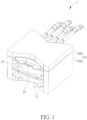
- FIG. 1 is a perspective view illustrating a magnetic component 1 according to an embodiment of the invention
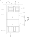
- FIG. 2 is a sectional view illustrating the magnetic component 1 shown in FIG. 1
- FIG. 3 is a top view illustrating an inner leg 100 shown in FIG. 2 .
- the magnetic component 1 of the invention may be a reactor, a transformer, an inductor or other magnetic components. As shown in FIGs. 1 and 2 , the magnetic component 1 includes a core 10, at least one coil 12 and a bobbin 13.
- the core 10 includes an inner leg 100 and at least one outer leg 102.
- the core 10 may include a first core member 10a and a second core member 10b disposed on the first core member 10a, wherein the inner leg 100 may be a central pillar disposed between the first core member 10a and the second core member 10b, and two outer legs 102 may be side pillars extending from the periphery of the first core member 10a.
- the types of the first core member 10a and the second core member 10b may be determined according to practical applications, so the invention is not limited to the embodiment shown in the figure.
- the at least one coil 12 is wound around the inner leg 100, and there is no coil wound around the outer legs 102.
- the type of the coil 12 may be a circular wire, a rectangular wire or a multi-stranded wire.
- the inner leg 100 is separated from an upper inner surface 104 of the core 10.
- the inner leg 100 (at least one individual portion of the inner leg 100) may be further separated from a lower inner surface 106 of the core 10, such that the inner leg 100 is floated or separated between the upper inner surface 104 and the lower inner surface 106.
- the upper inner surface 104 may be provided by the second core member 10b and the lower inner surface 106 may be provided by the first core member 10a.
- the bobbin 13 is disposed between the first core member 10a and the second core member 10b to support the floated inner leg 100.
- the at least one coil 12 is wound around the bobbin 13 and the inner leg 100.
- a spacer 11 may be disposed between the inner leg 100 and the upper inner surface 104 of the core 10, and another spacer 11 may be disposed between the inner leg 100 and the lower inner surface 106 of the core 10.
- the inner leg 100 is at least partially divided into a plurality of separated portions 1000 along a length direction of the inner leg 100.
- a length L2 of the plurality of separated portions 1000 may be larger than 1/3 of a length L1 of overall the inner leg 100 between the upper inner surface 104 of the core 10 and the lower inner surface 106 of the core 10.
- the length L2 of the plurality of separated portions 1000 may be equal to the length L1 of overall the inner leg 100, i.e. the inner leg 100 may be completely cut along the length direction to form the plurality of separated portions 1000, as shown in FIG. 2 .
- the inner leg 100 may be cut through a center, and volumes of the plurality of separated portions 1000 may be identical to each other.
- the inner leg 100 may be equally divided into four separated portions 1000 along the length direction of the inner leg 100, but the invention is not so limited.
- the number, volume and length of the separated portions 1000 may be determined according to practical applications.
- a thermal conductive filler 16 may be filled between the separated portions 1000 to improve heat dissipating efficiency, as shown in FIG. 2 .
- a thermal conductivity of the thermal conductive filler 16 may be greater than 0.3 W/mk, and a material of the thermal conductive filler may include epoxy, silicone, polyurethane (PU), phenolic resins, thermoplastic polyethylene terephthalate (PET), polyamide (PA), polyphenylene sulfide (PPS), polyetheretherketone (PEEK) and so on.
- a thermal conductive sheet 17 e.g. metal sheet or ceramic sheet, as shown in FIG. 3
- a thermal conductivity greater than the thermal conductive filler 16 may be disposed between the separated portions 1000 of the inner leg 10 and combined with the thermal conductive filler 16 covering the inner leg 100, thereby reducing core loss, temperature of inner leg and core stress.
- FIG. 4 is a sectional view illustrating the magnetic component 1 according to another embodiment of the invention.
- the length L2 of the plurality of separated portions 1000 may be equal to 1/2 of the length L1 of overall the inner leg 100.
- FIG. 5 is a sectional view illustrating the magnetic component 1 according to another embodiment of the invention.
- the inner leg 100 may be connected to the first core member 10a and there may be a floated (or separated) inner leg 100' located above the inner leg 100, and the length L2 of the plurality of separated portions 1000 may be equal to 1/2 of the length L1 of overall the inner leg 100. Similar to the embodiment shown in FIG. 4 , the length L2 of the plurality of separated portions 1000 shown in FIG. 5 may also be equal to 1/2 of the length L1 of overall the inner leg 100.
- a spacer 11 may be disposed between the inner leg 100' and the upper inner surface 104 of the core 10, and another spacer 11 may be disposed between the inner leg 100 and the inner leg 100'.
- the inner leg 100 is separated from the upper inner surface 104 of the core 10 and at least partially divided into a plurality of separated portions 1000 along the length direction of the inner leg 100. Since the inner leg 100 has the highest temperature and the heat cannot be easily dissipated from the inner leg 100, the inner leg 100 at least partially divided into a plurality of separated portions 1000 along the length direction of the inner leg 100 can reduce the cross-sectional area of the inner leg 100 perpendicular to the magnetic flux direction, so as to reduce the eddy current loss of the core 10. Furthermore, the invention only cuts the inner leg 100 without cutting the first core member 10a and/or the second core member 10b. Thus, the structure of the invention is easy to be assembled and the assembly tolerance is small.
- FIG. 6 is a perspective view illustrating a magnetic component 2 according to another embodiment of the invention
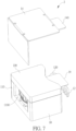
- FIG. 7 is a partial exploded view illustrating the magnetic component 2 shown in FIG. 6
- FIG. 8 is a perspective view illustrating a thermal conductive filler 16 covering a part of the coil 12 rather than wholly covering the coil 12
- FIG. 9 is a sectional view illustrating the magnetic component 2 shown in FIG. 6 .
- the magnetic component 2 further includes a heat dissipating member 14, a thermal conductive filler 16 and an insulating member 18, as shown in FIGs. 6 to 9 .
- the heat dissipating member 14 is disposed on the core 10, wherein the heat dissipating member 14 is in contact with a top surface 108 and a side surface 110 of the core 10.
- the side surface 110 has an opening 1100 and the heat dissipating member 14 covers the opening 1100.
- the thermal conductive filler 16 is filled at the opening 1100 of the side surface 110 and covers a part of the at least one coil 12 rather than wholly covering the at least one coil 12, as shown in FIG. 8 .
- a shape of the thermal conductive filler 16 at the opening 1100 is identical to a shape of the opening 1100 covered by the heat dissipating member 14. Furthermore, an end 120 of the at least one coil 12 may protrude from the core 10, and the heat dissipating member 14 may have a protruding portion 140 thermally coupled to the end 120 of the at least one coil 12.
- the thermal conductive filler 16 is filled into the core 10 from another opening opposite to the opening 1100, such that the thermal conductive filler 16 is filled at the opening 1100 and covers a part of the at least one coil 12 close to the opening 1100 without covering another part of the at least one coil 12 away from the opening 1100. Accordingly, the usage amount of the thermal conductive filler 16 can be saved. To balance the temperature, the coil 12 not covered by the thermal conductive filler 16 may be thermally coupled to the protruding portion 140 of the heat dissipating member 14.
- the insulating member 18 may be disposed between the end 120 of the at least one coil 12 and the protruding portion 140 of the heat dissipating member 14.
- the insulating member 18 can prevent the protruding portion 140 from contacting both ends of the coil 12 at the same time to cause short circuit.
- the outer surface of the heat dissipating member 14 may have a thicker electrical insulating layer, such that the insulating member 18 may be omitted.
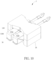
- FIG. 10 is a perspective view illustrating a magnetic component 3 according to another embodiment of the invention
- FIG. 11 is a partial exploded view illustrating the magnetic component 3 shown in FIG. 10
- FIG. 12 is a sectional view illustrating the magnetic component 3 shown in FIG. 10 .
- the at least one coil 12 may include an upper first coil 12a, a lower first coil 12b and a second coil 12c, as shown in FIG. 12 .
- Each of the upper first coil 12a and the lower first coil 12b may be a flat structure, and the second coil 12c may be formed by stacking a circular wire in multiple turns, such that a cross-sectional area of each of the upper first coil 12a and the lower first coil 12b may be larger than a cross-sectional area of the second coil 12c, but the invention is not so limited.
- the upper first coil 12a is disposed with respect to the upper inner surface 104 of the core 10
- the lower first coil 12b is disposed with respect to the lower inner surface 106 of the core 10
- the second coil 12c is disposed between the upper first coil 12a and the lower first coil 12b.
- the lower first coil 12b, the second coil 12c and the upper first coil 12a are stacked from bottom to top, and there is a gap G between the upper inner surface 104 of the core 10 and the upper first coil 12a, so as to absorb the assembly tolerance.
- the magnetic component 3 further includes a thermal conductive material 30 partially disposed in the gap G and in contact with the upper first coil 12a and the upper inner surface 104 of the core 10, such that the heat of the upper first coil 12a can be transferred to the upper portion of the core 10 through the thermal conductive material 30, so as to dissipate the heat from the upper first coil 12a.
- the thermal conductive material 30 may be, but is not limited to, gap filler, thermal pad or other thermal interface materials.
- there is no gap between the lower inner surface 106 of the core 10 and the lower first coil 12b the lower first coil 12b is thermally coupled to the lower inner surface 106 of the core 10, and the second coil 12c is not in contact with the thermal conductive material 30.
- a ratio of an area A1 of the thermal conductive material 30 to an area A2 of the upper first coil 12a covered by the core 10 may be between 30% and 50%.
- the magnetic component 3 further includes a bobbin 32 sleeved on the inner leg 100, wherein the bobbin 32 has an upper protruding platform 320 and a lower protruding platform 322 respectively corresponding to the upper inner surface 104 and the lower inner surface 106.
- the upper first coil 12a is disposed on an upper side of the upper protruding platform 320
- the lower first coil 12b is disposed on a lower side of the lower protruding platform 322, such that the upper first coil 12a is disposed with respect to the upper inner surface 104 of the core 10, and the lower first coil 12b is disposed with respect to the lower inner surface 106 of the core 10.
- the second coil 12c is located between the upper protruding platform 320 and the lower protruding platform 322, and there is a heat dissipating gap between the second coil 12c and the core 10 or the bobbin 32.
- the current and heat of the upper first coil 12a are larger than the current and heat of the second coil 12c.
- the usage amount of the thermal conductive material 30 may be reduced by 94% with the aforesaid structure.
- FIG. 13 is a perspective view illustrating a magnetic component 4 according to another embodiment of the invention
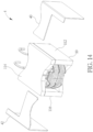
- FIG. 14 is a partial exploded view illustrating the magnetic component 4 shown in FIG. 13
- FIG. 15 is a sectional view illustrating the magnetic component 4 shown in FIG. 13 along line X-X
- FIG. 16 is a sectional view illustrating the magnetic component 4 shown in FIG. 13 along line Y-Y.
- the magnetic component 4 further includes a first heat dissipating member 40 and a second heat dissipating member 42, as shown in FIGs. 13 to 16 .
- three magnetic components 4 may be disposed in a single casing 44, but the invention is not so limited.
- the first heat dissipating member 40 may be disposed on a first side 112 and a top side 114 of the core 10
- the second heat dissipating member 42 may be disposed on a second side 116 and the top side 114 of the core 10, wherein the first side 112 is opposite to the second side 116.
- the first heat dissipating member 40 extends from the first side 112 to the top side 114
- the second heat dissipating member 42 extends from the second side 116 to the top side 114.
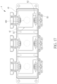
- the first heat dissipating member 40 and the second heat dissipating member 42 have a first joint region R1, a second joint region R2 and a third joint region R3 on the top side 114 between the first side 112 and the second side 116.
- the third joint region R3 is located between the first joint region R1 and the second joint region R2.
- the extending direction of the third joint region R3 is perpendicular to the extending directions of the first joint region R1 and the second joint region R2, but the invention is not so limited.
- projections of the first joint region R1 and the second joint region R2 do not overlap with the inner leg 100, and a projection of at least one of the first heat dissipating member 40 and the second heat dissipating member 42 overlaps with the inner leg 100, as shown in FIGs. 13 , 15 and 16 .
- the magnetic component further includes a thermal conductive filler 46 covering a lower portion of the core 10 and thermally coupled to a heat dissipating surface 48 below the lower portion.
- the projections of the first heat dissipating member 40 and the second heat dissipating member 42 may overlap with the inner leg 100 simultaneously (i.e. the projection of the third joint region R3 may overlap with the inner leg 100), and the joint distance D3 of the third joint region R3 may be between 0 and 3 mm.
- the joint distance D3 of the third joint region R3 may be 0, i.e.
- the first heat dissipating member 40 and the second heat dissipating member 42 are in contact with each other at the third joint region R3, and the first heat dissipating member 40 and the second heat dissipating member 42 may be symmetrical structures, such that the heat of the inner leg 100 transferred to the bottom of the first side 112 through the first heat dissipating member 40 is substantially equal to the heat of the inner leg 100 transferred to the bottom of the second side 116 through the second heat dissipating member 42, so as to optimize the heat dissipating efficiency and reduce the manufacturing cost.
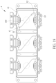
- FIG. 18 is a top view illustrating the magnetic component 4 according to another embodiment of the invention. As shown in FIG. 18 , the extending direction of the third joint region R3 is inclined with respect to the extending directions of the first joint region R1 and the second joint region R2.
- FIG. 19 is a perspective view illustrating a magnetic component 5 according to another embodiment of the invention
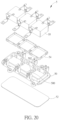
- FIG. 20 is an exploded view illustrating the magnetic component 5 shown in FIG. 19
- FIG. 21 is a sectional view illustrating the magnetic component 5 shown in FIG. 19 .
- the magnetic component 5 further includes a plastic casing 50, an insulating and thermal conductive substrate 52, and a thermal conductive filler 54, as shown in FIGs. 19 to 21 .
- three magnetic components 5 may be disposed in a single plastic casing 50, but the invention is not so limited.
- the plastic casing 50 is disposed on the insulating and thermal conductive substrate 52
- the core 10 of the magnetic component 5 is disposed in the plastic casing 50 and located on the insulating and thermal conductive substrate 52
- the thermal conductive filler 54 is filled in the plastic casing 50.
- the casing 50 of the magnetic component 5 made of plastic not only has better insulation, but also can concentrate and transfer most of the heat to the insulating and thermal conductive substrate 52 on the bottom.
- the plastic casing 50 can be used to cover the thermal conductive filler 54.
- the thermal conductive substrate 52 may be a metal core printed circuit board (MCPCB), a ceramic printed circuit board or an aluminum board with insulating layer, which has high thermal conductivity and high insulation at the same time.
- the plastic casing 50 may have a retracted structure 500 and a flow guide opening 502, and the thermal conductive filler 54 may cover the retracted structure 500 and the flow guide opening 502.
- the wall between the magnetic components 5 may have the flow guide opening 502, such that the thermal conductive filler 54 may flow between the magnetic components 5 through the flow guide opening 502 as being filled.
- the bottom of the plastic casing 50 may further have the retracted structure 500, such that the thermal conductive filler 54 may cover the retracted structure 500 and the flow guide opening 502, so as to reduce the usage amount of the thermal conductive filler 54.
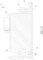
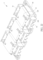
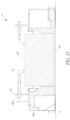
- FIG. 22 is a perspective view illustrating a magnetic component 6 according to another embodiment of the invention
- FIG. 23 is a sectional view illustrating the magnetic component 6 shown in FIG. 22 .
- the magnetic component 6 further includes a casing 60, as shown in FIGs. 22 and 23 .
- the casing 60 has a support structure 600.
- a terminal 62 is disposed on the support structure 600.
- An end 120 of the at least one coil 12 is bonded with the terminal 62 on the support structure 600.
- the support structure 600 extends downward from the terminal 62 to a support plane P where the casing 60 is located.
- the support structure 600 since the support structure 600 extends downward from the terminal 62 to the support plane P where the casing 60 of the magnetic component 6 is located, the bonding force F for bonding the end 120 of the coil 12 with the terminal 62 will be directly transferred to the support plane P through the support structure 600, such that the support structure 600 may withstand, for example, 650 tons of the bonding force F.
- the shape of the support structure 600 may be determined according to practical applications, so the invention is not limited to the embodiment shown in the figure.
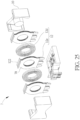
- FIG. 24 is a perspective view illustrating a magnetic component 7 according to another embodiment of the invention
- FIG. 25 is an exploded view illustrating the magnetic component 7 shown in FIG. 24
- FIG. 26 is an exploded view illustrating the secondary coils 12e and the insulating spacers 70 shown in FIG. 25
- FIG. 27 is a sectional view illustrating the magnetic component 7 shown in FIG. 24 .
- the at least one coil 12 includes at least one primary coil 12d and at least one secondary coil 12e stacked with each other, as shown in FIGs. 24 to 27 .
- the at least one primary coil 12d may be formed by stacking a circular wire in multiple turns.
- the at least one secondary coil 12e may be a foil structure.
- the at least one secondary coil 12e has a heat dissipating portion 122 protruding from the core 10, and the at least one primary coil 12d is retracted between the at least one secondary coil 12e without extending to the heat dissipating portion 122 of the at least one secondary coil 12e.
- the number of the primary coil 12d and the secondary coil 12e may be determined according to practical applications.
- the magnetic component 7 further includes a thermal conductive filler 16 partially filled between the at least one primary coil 12d and the at least one secondary coil 12e.
- the magnetic component 7 may further include at least one insulating spacer 70 disposed between the at least one primary coil 12d and the at least one secondary coil 12e, so as to improve insulation between the primary coil 12d and the secondary coil 12e.
- the thickness of the insulating spacer 70 may be between 50 ⁇ m and 100 ⁇ m, but the invention is not so limited.
- the inner leg 100 at least partially divided into a plurality of separated portions 1000 can be applied to all of the magnetic components 2-7 mentioned in the above.
Landscapes
- Engineering & Computer Science (AREA)
- Power Engineering (AREA)
- Chemical & Material Sciences (AREA)
- Composite Materials (AREA)
- Coils Or Transformers For Communication (AREA)
- Coils Of Transformers For General Uses (AREA)
- Housings And Mounting Of Transformers (AREA)
- Insulating Of Coils (AREA)
- Transformer Cooling (AREA)
Applications Claiming Priority (2)
| Application Number | Priority Date | Filing Date | Title |
|---|---|---|---|
| US202363454623P | 2023-03-24 | 2023-03-24 | |
| US18/613,093 US20240321498A1 (en) | 2023-03-24 | 2024-03-21 | Magnetic component |
Publications (2)
| Publication Number | Publication Date |
|---|---|
| EP4435806A2 true EP4435806A2 (de) | 2024-09-25 |
| EP4435806A3 EP4435806A3 (de) | 2024-12-18 |
Family
ID=90468824
Family Applications (1)
| Application Number | Title | Priority Date | Filing Date |
|---|---|---|---|
| EP24165872.3A Pending EP4435806A3 (de) | 2023-03-24 | 2024-03-25 | Magnetische komponente |
Country Status (4)
| Country | Link |
|---|---|
| US (1) | US20240321498A1 (de) |
| EP (1) | EP4435806A3 (de) |
| JP (1) | JP2024137940A (de) |
| TW (1) | TW202438351A (de) |
Family Cites Families (25)
| Publication number | Priority date | Publication date | Assignee | Title |
|---|---|---|---|---|
| JP2001176732A (ja) * | 1999-12-14 | 2001-06-29 | Hitachi Media Electoronics Co Ltd | トランス |
| US6980077B1 (en) * | 2004-08-19 | 2005-12-27 | Coldwatt, Inc. | Composite magnetic core for switch-mode power converters |
| FI20070160A0 (fi) * | 2007-02-26 | 2007-02-26 | Jarkko Salomaeki | Kuristinsydän |
| JP2008311394A (ja) * | 2007-06-14 | 2008-12-25 | Fdk Corp | トランス |
| JP5110735B2 (ja) * | 2008-10-10 | 2012-12-26 | 株式会社日本自動車部品総合研究所 | トランス |
| JP2010232272A (ja) * | 2009-03-26 | 2010-10-14 | Seiko Epson Corp | トランス |
| US9019062B2 (en) * | 2010-12-08 | 2015-04-28 | Epcos Ag | Inductive device with improved core properties |
| JP5974833B2 (ja) * | 2012-11-02 | 2016-08-23 | Tdk株式会社 | コイル装置 |
| CN103258624A (zh) * | 2013-05-13 | 2013-08-21 | 田村(中国)企业管理有限公司 | 混合磁路电感器 |
| JP2015065405A (ja) * | 2013-08-28 | 2015-04-09 | Tdk株式会社 | トランス |
| JP5769784B2 (ja) * | 2013-11-08 | 2015-08-26 | 三菱電機株式会社 | 車載用電力変換装置 |
| CN104715899A (zh) * | 2013-12-12 | 2015-06-17 | 台达电子企业管理(上海)有限公司 | 三相电抗器 |
| CN104851563B (zh) * | 2014-02-14 | 2018-01-30 | 台达电子企业管理(上海)有限公司 | 应用于电抗器的磁芯以及电抗器 |
| JP6520149B2 (ja) * | 2015-01-27 | 2019-05-29 | Tdk株式会社 | コイル装置 |
| DE112016007063T5 (de) * | 2016-07-13 | 2019-03-28 | Mitsubishi Electric Corporation | Leck-transformator |
| JP6509472B2 (ja) * | 2017-03-17 | 2019-05-08 | 三菱電機株式会社 | トランス |
| CN108666103B (zh) * | 2017-03-27 | 2022-04-26 | Tdk株式会社 | 线圈装置 |
| JP2018182204A (ja) * | 2017-04-19 | 2018-11-15 | 株式会社村田製作所 | コイル部品 |
| JP7056375B2 (ja) * | 2018-05-22 | 2022-04-19 | 株式会社オートネットワーク技術研究所 | 回路装置 |
| WO2020092636A1 (en) * | 2018-11-01 | 2020-05-07 | Bourns, Inc. | Low-profile housing for electronic components |
| JP2020202219A (ja) * | 2019-06-06 | 2020-12-17 | 株式会社デンソー | トランス |
| EP4152351A4 (de) * | 2020-06-24 | 2023-07-26 | Huawei Technologies Co., Ltd. | Elektrisches bauelement, leiterplatte und schaltnetzteil |
| GB2597670B (en) * | 2020-07-29 | 2022-10-12 | Murata Manufacturing Co | Thermal management of electromagnetic device |
| JP2024048499A (ja) * | 2022-09-28 | 2024-04-09 | キヤノン株式会社 | 回路基板、画像形成装置 |
| CN115410808A (zh) * | 2022-10-11 | 2022-11-29 | 贵阳顺络迅达电子有限公司 | 一种高可靠固定共模滤波电感器及其制作方法 |
-
2024
- 2024-03-21 US US18/613,093 patent/US20240321498A1/en active Pending
- 2024-03-25 TW TW113110919A patent/TW202438351A/zh unknown
- 2024-03-25 EP EP24165872.3A patent/EP4435806A3/de active Pending
- 2024-03-25 JP JP2024048508A patent/JP2024137940A/ja active Pending
Also Published As
| Publication number | Publication date |
|---|---|
| US20240321498A1 (en) | 2024-09-26 |
| EP4435806A3 (de) | 2024-12-18 |
| JP2024137940A (ja) | 2024-10-07 |
| TW202438351A (zh) | 2024-10-01 |
Similar Documents
| Publication | Publication Date | Title |
|---|---|---|
| CN110419085B (zh) | 变压器 | |
| JP2015065413A (ja) | トランス | |
| CN111344821B (zh) | 电力转换装置 | |
| JP6774726B2 (ja) | リアクトル | |
| TWI758226B (zh) | 具有導熱填充物的磁性元件結構 | |
| JP6516910B1 (ja) | 降圧コンバータ | |
| US20240062942A1 (en) | Coil device | |
| US20220108825A1 (en) | Coil Device and Power Conversion Device | |
| KR101821177B1 (ko) | 방열성이 우수한 박막형 변압기 | |
| EP4435805A1 (de) | Magnetische komponente | |
| US20240321498A1 (en) | Magnetic component | |
| JP2020068367A (ja) | リアクトル | |
| JP2019145719A (ja) | モジュール | |
| US20180197669A1 (en) | Ceramic insulated transformer | |
| US20240029936A1 (en) | Magnetic component | |
| CN118692792A (zh) | 磁性元件 | |
| CN118692793A (zh) | 磁性元件 | |
| CN118692787A (zh) | 线圈装置 | |
| JP2001237125A (ja) | コイルボビン及びトランス | |
| US12417875B2 (en) | Electronic device | |
| JP7676195B2 (ja) | コイル装置 | |
| JP6459002B2 (ja) | トランス | |
| JP2020077763A (ja) | リアクトルの冷却構造及び電力変換装置 | |
| CN112805797B (zh) | 电抗器 | |
| JP6443635B2 (ja) | トランス及びトランスの製造方法 |
Legal Events
| Date | Code | Title | Description |
|---|---|---|---|
| PUAI | Public reference made under article 153(3) epc to a published international application that has entered the european phase |
Free format text: ORIGINAL CODE: 0009012 |
|
| STAA | Information on the status of an ep patent application or granted ep patent |
Free format text: STATUS: THE APPLICATION HAS BEEN PUBLISHED |
|
| AK | Designated contracting states |
Kind code of ref document: A2 Designated state(s): AL AT BE BG CH CY CZ DE DK EE ES FI FR GB GR HR HU IE IS IT LI LT LU LV MC ME MK MT NL NO PL PT RO RS SE SI SK SM TR |
|
| PUAL | Search report despatched |
Free format text: ORIGINAL CODE: 0009013 |
|
| AK | Designated contracting states |
Kind code of ref document: A3 Designated state(s): AL AT BE BG CH CY CZ DE DK EE ES FI FR GB GR HR HU IE IS IT LI LT LU LV MC ME MK MT NL NO PL PT RO RS SE SI SK SM TR |
|
| RIC1 | Information provided on ipc code assigned before grant |
Ipc: H01F 27/02 20060101ALI20241112BHEP Ipc: H01F 27/22 20060101ALI20241112BHEP Ipc: H01F 3/10 20060101AFI20241112BHEP |
|
| STAA | Information on the status of an ep patent application or granted ep patent |
Free format text: STATUS: REQUEST FOR EXAMINATION WAS MADE |
|
| 17P | Request for examination filed |
Effective date: 20250617 |