EP4428330A1 - Profilschiene für eine türführung eines fahrzeuges - Google Patents
Profilschiene für eine türführung eines fahrzeuges Download PDFInfo
- Publication number
- EP4428330A1 EP4428330A1 EP24161355.3A EP24161355A EP4428330A1 EP 4428330 A1 EP4428330 A1 EP 4428330A1 EP 24161355 A EP24161355 A EP 24161355A EP 4428330 A1 EP4428330 A1 EP 4428330A1
- Authority
- EP
- European Patent Office
- Prior art keywords
- profile rail
- connecting piece
- piece
- plug
- elements
- Prior art date
- Legal status (The legal status is an assumption and is not a legal conclusion. Google has not performed a legal analysis and makes no representation as to the accuracy of the status listed.)
- Granted
Links
Images


Classifications
-
- E—FIXED CONSTRUCTIONS
- E05—LOCKS; KEYS; WINDOW OR DOOR FITTINGS; SAFES
- E05D—HINGES OR SUSPENSION DEVICES FOR DOORS, WINDOWS OR WINGS
- E05D15/00—Suspension arrangements for wings
- E05D15/06—Suspension arrangements for wings for wings sliding horizontally more or less in their own plane
- E05D15/10—Suspension arrangements for wings for wings sliding horizontally more or less in their own plane movable out of one plane into a second parallel plane
- E05D15/1042—Suspension arrangements for wings for wings sliding horizontally more or less in their own plane movable out of one plane into a second parallel plane with transversely moving carriage
-
- B—PERFORMING OPERATIONS; TRANSPORTING
- B60—VEHICLES IN GENERAL
- B60J—WINDOWS, WINDSCREENS, NON-FIXED ROOFS, DOORS, OR SIMILAR DEVICES FOR VEHICLES; REMOVABLE EXTERNAL PROTECTIVE COVERINGS SPECIALLY ADAPTED FOR VEHICLES
- B60J5/00—Doors
- B60J5/04—Doors arranged at the vehicle sides
- B60J5/06—Doors arranged at the vehicle sides slidable; foldable
-
- E—FIXED CONSTRUCTIONS
- E05—LOCKS; KEYS; WINDOW OR DOOR FITTINGS; SAFES
- E05D—HINGES OR SUSPENSION DEVICES FOR DOORS, WINDOWS OR WINGS
- E05D15/00—Suspension arrangements for wings
- E05D15/06—Suspension arrangements for wings for wings sliding horizontally more or less in their own plane
- E05D15/0621—Details, e.g. suspension or supporting guides
- E05D15/0626—Details, e.g. suspension or supporting guides for wings suspended at the top
- E05D15/0652—Tracks
-
- E—FIXED CONSTRUCTIONS
- E05—LOCKS; KEYS; WINDOW OR DOOR FITTINGS; SAFES
- E05D—HINGES OR SUSPENSION DEVICES FOR DOORS, WINDOWS OR WINGS
- E05D15/00—Suspension arrangements for wings
- E05D15/06—Suspension arrangements for wings for wings sliding horizontally more or less in their own plane
- E05D15/0621—Details, e.g. suspension or supporting guides
- E05D15/066—Details, e.g. suspension or supporting guides for wings supported at the bottom
- E05D15/0686—Tracks
-
- E—FIXED CONSTRUCTIONS
- E05—LOCKS; KEYS; WINDOW OR DOOR FITTINGS; SAFES
- E05D—HINGES OR SUSPENSION DEVICES FOR DOORS, WINDOWS OR WINGS
- E05D15/00—Suspension arrangements for wings
- E05D15/06—Suspension arrangements for wings for wings sliding horizontally more or less in their own plane
- E05D15/10—Suspension arrangements for wings for wings sliding horizontally more or less in their own plane movable out of one plane into a second parallel plane
- E05D15/1042—Suspension arrangements for wings for wings sliding horizontally more or less in their own plane movable out of one plane into a second parallel plane with transversely moving carriage
- E05D2015/1055—Suspension arrangements for wings for wings sliding horizontally more or less in their own plane movable out of one plane into a second parallel plane with transversely moving carriage with slanted or curved track sections or cams
-
- E—FIXED CONSTRUCTIONS
- E05—LOCKS; KEYS; WINDOW OR DOOR FITTINGS; SAFES
- E05Y—INDEXING SCHEME ASSOCIATED WITH SUBCLASSES E05D AND E05F, RELATING TO CONSTRUCTION ELEMENTS, ELECTRIC CONTROL, POWER SUPPLY, POWER SIGNAL OR TRANSMISSION, USER INTERFACES, MOUNTING OR COUPLING, DETAILS, ACCESSORIES, AUXILIARY OPERATIONS NOT OTHERWISE PROVIDED FOR, APPLICATION THEREOF
- E05Y2201/00—Constructional elements; Accessories therefor
- E05Y2201/60—Suspension or transmission members; Accessories therefor
- E05Y2201/622—Suspension or transmission members elements
- E05Y2201/684—Rails; Tracks
-
- E—FIXED CONSTRUCTIONS
- E05—LOCKS; KEYS; WINDOW OR DOOR FITTINGS; SAFES
- E05Y—INDEXING SCHEME ASSOCIATED WITH SUBCLASSES E05D AND E05F, RELATING TO CONSTRUCTION ELEMENTS, ELECTRIC CONTROL, POWER SUPPLY, POWER SIGNAL OR TRANSMISSION, USER INTERFACES, MOUNTING OR COUPLING, DETAILS, ACCESSORIES, AUXILIARY OPERATIONS NOT OTHERWISE PROVIDED FOR, APPLICATION THEREOF
- E05Y2600/00—Mounting or coupling arrangements for elements provided for in this subclass
- E05Y2600/50—Mounting methods; Positioning
- E05Y2600/52—Toolless
- E05Y2600/53—Snapping
-
- E—FIXED CONSTRUCTIONS
- E05—LOCKS; KEYS; WINDOW OR DOOR FITTINGS; SAFES
- E05Y—INDEXING SCHEME ASSOCIATED WITH SUBCLASSES E05D AND E05F, RELATING TO CONSTRUCTION ELEMENTS, ELECTRIC CONTROL, POWER SUPPLY, POWER SIGNAL OR TRANSMISSION, USER INTERFACES, MOUNTING OR COUPLING, DETAILS, ACCESSORIES, AUXILIARY OPERATIONS NOT OTHERWISE PROVIDED FOR, APPLICATION THEREOF
- E05Y2600/00—Mounting or coupling arrangements for elements provided for in this subclass
- E05Y2600/60—Mounting or coupling members; Accessories therefor
-
- E—FIXED CONSTRUCTIONS
- E05—LOCKS; KEYS; WINDOW OR DOOR FITTINGS; SAFES
- E05Y—INDEXING SCHEME ASSOCIATED WITH SUBCLASSES E05D AND E05F, RELATING TO CONSTRUCTION ELEMENTS, ELECTRIC CONTROL, POWER SUPPLY, POWER SIGNAL OR TRANSMISSION, USER INTERFACES, MOUNTING OR COUPLING, DETAILS, ACCESSORIES, AUXILIARY OPERATIONS NOT OTHERWISE PROVIDED FOR, APPLICATION THEREOF
- E05Y2800/00—Details, accessories and auxiliary operations not otherwise provided for
- E05Y2800/20—Combinations of elements
- E05Y2800/205—Combinations of elements forming a unit
-
- E—FIXED CONSTRUCTIONS
- E05—LOCKS; KEYS; WINDOW OR DOOR FITTINGS; SAFES
- E05Y—INDEXING SCHEME ASSOCIATED WITH SUBCLASSES E05D AND E05F, RELATING TO CONSTRUCTION ELEMENTS, ELECTRIC CONTROL, POWER SUPPLY, POWER SIGNAL OR TRANSMISSION, USER INTERFACES, MOUNTING OR COUPLING, DETAILS, ACCESSORIES, AUXILIARY OPERATIONS NOT OTHERWISE PROVIDED FOR, APPLICATION THEREOF
- E05Y2900/00—Application of doors, windows, wings or fittings thereof
- E05Y2900/50—Application of doors, windows, wings or fittings thereof for vehicles
- E05Y2900/53—Type of wing
- E05Y2900/531—Doors
Definitions
- the invention relates to a profile rail for a door guide of a vehicle.
- Door guides for vehicles equipped with sliding doors for people to get in and out are known from practice. These sliding doors are often guided with suitable guide or holding devices in a one-piece guide rail, which is attached to the vehicle body.
- a curved section of a one-piece profile rail or guide rail presents problems for guide means, such as rollers on a door roller carriage, since areas of the curved section can constrict or bend during production, e.g. when stretch bending the profile rail, so that up to now it was necessary to work with very high manufacturing tolerances in order to be able to guarantee that the guide means run reasonably smoothly, especially in the curved section of the profile rail.
- CN 108661476 B shows a profile rail for a door guide of a vehicle, comprising a first profile rail piece with a first end face and a second end face and a connecting piece, wherein the connecting piece has a first end and a second end.
- the first end of the connecting piece has a first end-face connection region for arranging abutting the first end face of the first profile rail piece, wherein the profile rail piece and the connecting piece comprise elongated holes so that the profile rail piece and the connecting piece can be fastened to a surface via a screw connection.
- the profile rail piece and the connecting piece are welded together.
- EN 10 2008 021 802 A1 shows a door guide of a vehicle with a profile rail divided into two along its longitudinal extension, which has a lower and an upper guide rail, wherein the lower and upper guide rails are connected to one another by riveting.
- the upper guide rail of the profile rail is on the one hand a deep-drawn component
- the lower guide rail of the profile rail is on the other hand a rolled and stretch-bent component.
- Means for guiding and supporting a vehicle door can be inserted into the profile rail and can be moved along the profile rail.
- the protruding profile rail consists of at least two components to be connected, namely an upper guide rail and a lower guide rail.
- the assembled profile rail corresponds to a one-piece component, since it is divided in two along its longitudinal direction.
- curved profile rails that correspond to a structure of the protruding profile rail can have large dimensions, among other things due to the different manufacturing methods for the upper and lower guide rails.
- thermal expansion and/or thermal shrinkage due to temperature changes can lead to undesirable dimensions with regard to the profile rail to be installed.
- EN 20 2010 010 125 U1 shows a connection for at least two profile rail pieces.
- the connection comprises a first profile rail piece, a second profile rail piece and a connecting piece made of plastic.
- the connecting piece is glued to the first profile rail piece and to the second profile rail piece.
- the first profile rail piece and the second profile rail piece are arranged in such a way that a first front end region of the first profile rail piece and a second front end region of the second profile rail piece abut one another.
- the connecting piece has an adhesive coating on an underside, which is additionally equipped with a release film.
- the connecting piece is arranged both adhesively on a first surface of the first profile rail piece and adhesively on a second surface of the second profile rail piece.
- US 2017 021 13 06 A1 shows a one-piece profile rail for a door guide of a vehicle, comprising a first profile rail piece with a first end face and a second end face and a connecting piece, wherein the connecting piece has a first end and a second end.
- the connecting piece is designed as an intermediate element in order to set a certain distance between a vehicle body and the profile rail piece.
- the connecting piece is arranged between the vehicle body and the profile rail piece.
- the connecting piece is aligned essentially parallel to the profile rail piece.
- EN 10 2009 033 136 A1 shows a profile rail, wherein the profile rail comprises plastic components, wherein the plastic components are made of a radiation-crosslinked plastic material.
- a profile rail for a door guide of a Vehicle comprising a first profile rail piece with a first end face and a second end face, and a connecting piece, wherein the connecting piece has a first end and a second end, wherein the first end of the connecting piece has a first end-side connection region for connecting to the first profile rail piece, wherein the connecting piece is designed as a separate profile rail piece, and wherein the connecting piece can be connected via the first end-side connection region to at least one end face of the first profile rail piece by means of a plug-in system.
- the profile rail is characterized in that the connecting piece comprises an upper connecting piece part and a lower connecting piece part, and in that the upper connecting piece part and the lower connecting piece part can be connected to one another along a connecting line that runs transversely with respect to the first end-side connection region at least in sections.
- the flexibility of an assembly is advantageously increased by means of a two-part connecting piece in order to compensate for any manufacturing tolerances.
- a profile rail is created for a door guide of a vehicle.
- the profile rail comprises a first profile rail piece with a first end face and a second end face.
- the profile rail further comprises a connecting piece which has a first end and a second end.
- the first end of the connecting piece has a first end-face connection area for connecting to the first profile rail piece, wherein the connecting piece is designed as a separate profile rail piece, and wherein the connecting piece can be connected to at least one end face of the first profile rail piece via the first end-face connection area by means of a plug-in system.
- the profile rail can advantageously comprise custom-made individual parts that can be connected to one another using an intuitive plug-in system, so that a profile rail with a specific length and a specific course can be provided.
- any inaccuracies e.g. due to non-compliance with manufacturing tolerances or possible thermal length changes, can be compensated for during assembly.
- a plug-in system also offers the advantage that a profile rail can be disassembled or extended at any time, for example to variably adapt the profile rail in terms of its length and course. Furthermore, rejects due to faulty production of a profile rail are avoided, as the individual standardized profile rail pieces can be detachably connected and can therefore be used in other profile rails.
- Another advantage of a plug-in system for a door guide is that if a section of the profile rail is damaged, e.g. as a result of a collision, the entire profile rail does not necessarily have to be replaced, but only the defective section is replaced with an intact section of the profile rail.
- a profile rail for a door guide of a vehicle comprising a first profile rail piece with a first end face and a second end face, and a connecting piece, wherein the connecting piece has a first end and a second end, wherein the first end of the connecting piece has a first end-face connection region for connecting to the first profile rail piece, wherein the connecting piece is designed as a separate profile rail piece and wherein the connecting piece can be connected via the first front-side connection region to at least one front side of the first profile rail piece by means of a plug-in system, wherein the first front-side connection region is arranged in a first connection plane which has a first angle to a first plane normal to an extension of the connecting piece.
- An inclined first connection region of the connecting piece and a complementary inclined first front side of the first profile rail piece advantageously improves the plugging together of the connecting piece and the first profile rail piece, since contact between the first connection region of the connecting piece and the first front side of the first profile rail piece is almost gap-free. Furthermore, roller properties of a support roller of the door guide are advantageously promoted, since the support roller is displaced smoothly and jerk-free at a transition between the connecting piece and the first profile rail piece due to an almost gap-free and stepless design of the transition, wherein a displacement direction of the support roller encounters a gap at an angle of less than 90 °.
- a profile rail for a door guide of a vehicle comprising a first profile rail piece with a first end face and a second end face, and a connecting piece, wherein the connecting piece has a first end face connection area for connecting to the first profile rail piece, wherein the connecting piece is designed as a separate profile rail piece, and wherein the connecting piece can be connected via the first end face connection area to at least one end face of the first profile rail piece by means of a plug-in system, wherein the first profile rail piece has a hollow chamber that is continuous at least in sections on a side facing the vehicle, that a slot recess is formed in the hollow chamber, and that a threaded bolt with a head piece can be inserted into the hollow chamber.
- the profile rail can be connected to the vehicle body using a concealed fastener, so that no disturbing elements, such as screws, are visible to an outside observer, and a possible source of corrosion is eliminated.
- a concealed fastener can be moved within the hollow chamber, so that mounting the profile rail to the vehicle body is made easier by allowing manufacturing tolerances to be compensated for by moving the fastener.
- a profile rail for a door guide of a vehicle comprising a first profile rail piece with a first end face and a second end face, and a connecting piece, wherein the connecting piece has a first end face connection area for connecting to the first profile rail piece, wherein the connecting piece is designed as a separate profile rail piece, and wherein the connecting piece can be connected via the first end face connection area to at least one end face of the first profile rail piece by means of a plug-in system, wherein the connecting piece has at least one locking element with a flexible, elastic locking lug, and that the locking lug of the connecting piece can be locked and unlocked with a counter-locking element designed as a recess of the first profile rail piece.
- the connecting piece is plugged together with the first profile rail piece simply and quickly, with immediate locking taking place, and further connecting means can be dispensed with, so that assembly is intuitive, tool-free and quick.
- the first profile rail piece expediently has, on a side facing the vehicle, a hollow chamber which is at least partially continuous, wherein a slot recess is expediently formed in the hollow chamber, and wherein a threaded bolt with a head piece can expediently be inserted into the hollow chamber.
- the profile rail can advantageously be connected to a vehicle body using a concealed connecting means, so that no disturbing elements, e.g. screws, are visible to an observer from the outside, and a possible source of corrosion is advantageously eliminated.
- a further advantage is that the connecting means can be moved within the hollow chamber, so that mounting the profile rail to the vehicle body is simplified by being able to compensate for manufacturing tolerances by moving the connecting means.
- the threaded bolt and the head piece are designed separately, whereby the threaded bolt and the head piece can be connected to one another, e.g. via a screw connection.
- the threaded bolt could alternatively be designed as a rivet in order to connect the profile rail to a vehicle body using a rivet connection.
- the slot recess has a width which is slightly larger than an outer diameter of the threaded bolt, so that the threaded bolt protrudes from the slot recess and so that the threaded bolt can be displaced along the slot recess with some play.
- the hollow chamber and the slot recess expediently extend in the longitudinal direction of the first profile rail section. This advantageously allows a fastening means inserted into the hollow chamber, e.g. a head piece with a screwed-on threaded bolt or a hammer head screw, to be reliably displaced along the first profile rail section, thereby increasing ease of assembly.
- a fastening means inserted into the hollow chamber e.g. a head piece with a screwed-on threaded bolt or a hammer head screw
- the first front-side connection area is arranged in a first connection plane, which has a first angle to a first plane normal to an extension of the connecting piece.
- an oblique first connection area of the connecting piece and a complementary oblique first front side of the first profile rail piece improves the plugging together of the connecting piece and the first profile rail piece, since contact between the first Connection area of the connecting piece and the first front side of the first profile rail piece is almost gap-free.
- roller properties of a support roller of the door guide are advantageously promoted, since the support roller is moved smoothly and jerk-free at a transition between the connecting piece and the first profile rail piece due to an almost gap-free and stepless design of the transition, whereby a direction of movement of the support roller encounters a gap at an angle of less than 90°.
- the first connection plane expediently runs at a first angle with respect to the normal plane of the front connection area of between 20° and 70°, preferably between 25° and 35° and particularly preferably between 28° and 32°. It has been advantageously determined that a front connection area at an angle of approximately 30° +/- 2° produces optimal smoothness and ease of movement of a support roller when displaced within the profile rail.
- the second end of the connecting piece has a second front-side connection area for connecting to a second profile rail piece, that the second front-side connection area is arranged in a second connection plane which has a second angle to a second plane normal to an extension of the connecting piece, and that the second connection plane runs at a second angle with respect to the second normal plane of the second front-side connection area between 20° and 70°, preferably between 25° and 35° and particularly preferably between 28° and 32°.
- An oblique second connection area of the connecting piece and a complementary oblique first front side of the second profile rail piece advantageously improves the plugging together of the connecting piece and the second profile rail piece, since contact between the second connection area of the connecting piece and the first front side of the second profile rail piece is almost gap-free.
- roller properties of a support roller of the door guide This is advantageous because the support roller is moved smoothly and without jolts at a transition between the connecting piece and the second profile rail section thanks to a transition that is almost gap-free and stepless, with the support roller moving in the direction of travel encountering a gap at an angle of less than 90°. It was also found that a front-side connection area at an angle of around 30° +/- 2° creates optimal smoothness and ease of movement of the support roller when moving within the profile rail.
- the first connection level of the first front connection area extends away from the first normal level in an outward direction on a side facing the vehicle.
- the stability of the profile rail is increased in this way, which ensures reliable opening and closing of a vehicle door.
- the second connection level of the second front connection area extends away from the second normal level in an outward direction on a side facing the vehicle.
- the stability of the profile rail is increased in this way, which ensures reliable opening and closing of a vehicle door.
- the first front-side connection area has projections designed as plug-in elements and/or locking elements, and that the plug-in elements and the locking elements are arranged perpendicularly with respect to the first normal plane.
- the second frontal connection area expediently has projections designed as plug-in elements and/or locking elements, wherein the plug-in elements and the locking elements are expediently arranged perpendicularly with respect to the second normal plane.
- an intuitive plug-in system is provided, according to which assembly is quick and without tools.
- the first end face and/or the second end face of the first profile rail piece is expediently designed to be complementary to the first end face connection area of the connecting piece. Very good contact is advantageously ensured via complementary connection surfaces, whereby the assembled profile rail offers a flush and gap-free running surface, enabling a support roller to be moved quietly and smoothly.
- the first connection level and the second connection level are parallel. This advantageously increases ease of assembly, so that the profile rail can be assembled intuitively.
- the connecting piece has at least one locking element with a flexible, elastic locking lug, and that the locking lug of the connecting piece can be locked and unlocked with a counter-locking element in the first profile rail piece, which is designed as a recess.
- the connecting piece is advantageously plugged together with the first profile rail piece easily and quickly, with immediate locking taking place, and further connecting means can be dispensed with, so that assembly is intuitive, tool-free and quick.
- the upper connecting piece part has an upper locking lug and that the lower connecting piece part has a lower locking lug.
- the upper locking lug and the lower locking lug are arranged parallel to each other, with the upper locking lug and the lower locking lug preferably being arranged facing away from each other.
- forces from almost all directions can advantageously be absorbed and transmitted in a locked state, so that a reliable and stable profile rail is provided.
- the upper connecting piece part and the lower connecting piece part are expediently connected to one another by plugging.
- a simple plug-in system is advantageously provided, which advantageously ensures the stability of the assembled connecting piece. Furthermore, plugging together is advantageously quick and tool-free.
- the upper connecting piece part and the lower connecting piece part are made of the same material.
- the same materials have the same coefficient of thermal expansion, so that temperature-related thermal expansion does not produce any undesirable effects.
- the same choice of material advantageously results in lower manufacturing costs.
- the connecting piece is expediently made of a plastic material.
- the plastic material used for the connecting piece can be, for example, polyamide, polyvinyl chloride, polyoxymethylene or polypropylene, etc., which is manufactured using an injection molding process. Because plastic is much more flexible than steel or aluminum, a connecting piece made of plastic can be connected particularly easily to other profile rail pieces by allowing the connecting piece to be elastically deformed to a certain extent. Furthermore, a connecting piece made of plastic can also be plastically deformed particularly well. This is important, for example, in a possible subsequent joining process in which a clinching process (so-called clinching) is used. Due to the lower density of a plastic compared to a metallic component, the The total weight of a composite profile rail is advantageously reduced.
- a plastic connector can act as a buffer in the event of thermal changes in length and thus compensate for any changes in length of the metal components.
- Another advantage of a connector made of a plastic material is its high corrosion resistance.
- the operation of a composite profile rail in which plastic materials are used is advantageously quiet, as plastics absorb disturbing noises and dampen possible vibrations. Because the connector is manufactured using an injection molding process, even relatively complicated shapes for the connector can be produced quickly, both inexpensively and in large quantities.
- the first profile rail piece is preferably made from a metallic material.
- straight profile rail pieces are preferably made from an aluminum alloy using an extrusion process.
- the respective profile rail piece can be subjected to an anodizing process or a coating process, for example, before final assembly on a vehicle body, in order to prevent wear and corrosion.
- the first profile rail piece is made of a plastic material.
- the plastic material for the first profile rail piece and the connecting piece can be, for example, a polyamide, polyvinyl chloride, polyoxymethylene or polypropylene, etc. Due to the lower density of a plastic compared to a metallic component, the overall weight of the profile rail is advantageously reduced. Furthermore, material and production costs can be significantly reduced by the entire profile rail is made of plastic. All profile rail pieces, including the connecting piece, are manufactured cost-effectively using an injection molding process. In addition, the profile rail made of plastic is advantageously quiet to operate, as plastics absorb disturbing noises and dampen possible vibrations.
- profile rail pieces used which are made of the same material, have the same mechanical, thermal and chemical properties, so that in the event of a thermal change in length, for example, the profile rail undergoes uniform thermal expansion or uniform thermal contraction due to the same thermal expansion coefficients. This advantageously minimizes any internal stresses that may occur within the assembled profile rail, which always ensures reliable and quiet movement of support and guide rollers.
- the plastic material is particularly preferably designed as a radiation-crosslinked plastic material.
- inexpensive technical plastics can be modified by means of radiation crosslinking in terms of their mechanical, thermal and chemical properties so that they correspond to the properties of high-performance plastics.
- Radiation-crosslinked plastics therefore advantageously have an increased load-bearing capacity and an increased load-bearing capacity and thus also an increased service life of the door guide.
- the overall weight of the profile rail is advantageously reduced considerably as a result of the plastic material used, and on the other hand, the profile rail advantageously has very good mechanical, thermal and chemical properties thanks to radiation crosslinking.
- the individual profile rail pieces and connecting pieces can be produced quickly and in large quantities using a cost-effective injection molding process.
- the second end of the connecting piece has a second frontal connection area for connection to a second profile rail piece, wherein the second profile rail piece has a first front side and a second front side.
- the connecting piece can be connected via the second front-side connection area to at least one front side of the second profile rail piece by means of a plug-in system.
- the connecting piece can advantageously be used both as a middle part between two profile rail pieces and as an end piece of a profile rail. This increases both the functionality and the ease of assembly with regard to production and application of the profile rail.
- the connecting piece can have a second front-side connection area which, like the first profile rail piece, can be connected to the second profile rail piece by means of a plug-in system.
- the second profile rail piece can be made either from steel or from an aluminum alloy or from a plastic material corresponding to the first profile rail piece.
- the connecting piece has at least one curved section with at least one radius.
- the connecting piece is advantageously used as a type of corner connector or as a type of angle connector, whereby an assembled profile rail runs around a corner or at least partially along a curved path using the corresponding profile rail pieces.
- a connecting piece designed as a corner connector which for example connects at least two profile rail pieces to one another, advantageously has an angle between 90° and 150°, preferably between 140° and 100° and particularly preferably between 130° and 110°.
- An inner radius of the connecting piece is preferably between 50 millimeters and 100 millimeters and particularly preferably between 60 millimeters and 70 millimeters, whereby corresponding support and guide rollers of the door guide can be easily displaced along a curved guide path within the connecting piece.
- the connecting piece is largely responsible for the angle between the first profile rail piece and the second profile rail piece, so that, depending on the application, individual connecting pieces with different angles and radii can be used, which an assembly that is both easy to assemble and flexible is provided for assembling an individual profile rail and then mounting it to a vehicle body.
- Straight and curved connectors are therefore advantageous in order to provide profile rails with curved sections quickly and efficiently using a modular plug-in system.
- the first profile rail piece expediently has a first guide profile and the connecting piece has a second guide profile.
- the first guide profile of the first profile rail piece and the second guide profile of the connecting piece are each arranged in alignment and flush with one another when the profile rail is assembled, whereby means for guiding and supporting a vehicle door can be displaced along the assembled profile rail.
- the respective guide profiles are advantageously designed to be identical with respect to the individual profile rail pieces or connecting pieces.
- the transitions between the individual profile rail pieces or connecting pieces are designed to be stepless and almost gap-free when the profile rail is assembled.
- the respective guide profiles or at least the respective guide tracks are aligned flush and aligned with respect to the connecting piece and the at least one profile rail piece and are aligned end to end with respect to one another.
- a guide track refers to the areas of the guide profile that are contacted by the guide and support rollers and other possible sliding elements when the vehicle door is moved.
- the entire guide track of the guide profile of the profile rail is advantageously smooth. This means that a vehicle door can be opened and closed very easily, with great smoothness and low noise, either manually or by means of a motor.
- the first profile rail piece and the connecting piece each have a C-shaped cross-section.
- a C-shaped cross-section is advantageously particularly well suited to inserting corresponding guide and support rollers into the guide profile of the profile rail and to reliably move them in it without undesirable decoupling between the profile rail and the guide and support rollers.
- manufacturing a C-shaped component e.g. using an injection molding process for plastic parts or using an extrusion process for metal parts, is simple and cost-effective, since a simple geometry is preferred overall with regard to the profile rail pieces.
- a C-shaped cross-section advantageously has very good mechanical stability, which ensures that the profile rail has a high load-bearing and load-bearing capacity.
- one leg of the C-shaped profile rail protrudes at an angle between 80° and 135°, preferably between 90° and 110° and particularly preferably between 90° and 100°.
- the angled protruding leg of the C-shaped profile rail advantageously serves as a type of abutment, so that the guide and support rollers cannot fall out or slip out of the profile rail sideways. The guide and support rollers are thus always reliably held in position within the guideway provided for the guide and support rollers.
- the connecting piece comprises at least one plug element and at least one guide element.
- the corresponding connection areas of the connecting piece advantageously have male connecting elements for a plug connection with profile rail pieces.
- These connecting elements include, among others, guide and holding aids designed as vertical plates, each of which protrudes from the front of the connecting piece.
- the connecting elements also include plug and locking elements, each of which protrudes from the front of the connecting piece.
- the guide and holding aids of the connecting piece support an aligned and flush alignment with another profile rail piece in an assembled state of the profile rail.
- the guide and holding aids as well as the plug and locking elements advantageously prevent the connecting piece from having a certain amount of play in an assembled state of the profile rail, so that the connecting piece advantageously does not change its position in any direction with respect to the connected profile rail piece.
- the plug elements can be equipped with at least one flexible, elastic locking lug, so that the connecting piece has at least one locking element.
- a combination of locking and plug elements advantageously serves to provide a stable, force-fitting or positive plug connection of a connecting piece with another profile rail piece. This is preferably a detachable plug connection with narrow tolerances, so that the connecting piece is tightly connected to the profile rail piece.
- the profile rail piece preferably has corresponding female hollow chamber elements with respect to the male connecting elements of the connecting piece. Furthermore, the profile rail piece preferably has at least one corresponding counter-locking element, which is designed as a recess.
- the elastic locking element or the elastic locking lug of the connecting piece can engage in the counter-locking element with a force and a form fit.
- the corresponding male and female connecting elements advantageously provide a simple, quick and intuitive plug-in system for mounting a profile rail, whereby no additional tools are required.
- the connecting piece can comprise female hollow chamber elements at least at one end, with at least one hollow chamber element having at least one counter-latching element.
- the first profile rail piece and the second profile rail piece can accordingly each have associated male plug and latching elements at least on one end face for a plug connection with the connecting piece.
- the at least one guide element of the connecting piece rests in the longitudinal direction of the first profile rail piece on an inner side of the first profile rail piece or on an outer side of the first profile rail piece.
- the connecting piece can advantageously be held in a stable position in an assembled state of the profile rail, in particular against possible torsional forces, so that undesirable twisting of the connecting piece is always prevented.
- the protruding plug-in, locking and guide elements advantageously prevent the connecting piece from changing its position in any direction in an assembled state of the profile rail with respect to the first profile rail piece.
- possible torsional twisting of the connecting piece is prevented, so that the respective guide profiles or guide tracks are always aligned and flush with one another in order to ensure smooth, quiet and low-noise displacement of support and guide rollers within the entire profile rail.
- Fig.1 shows in a perspective schematic view of an exploded view a first embodiment of a three-piece profile rail 1, which comprises a first straight profile rail piece 2, a second straight profile rail piece 3 and a curved connecting piece 4 arranged between the two profile rail pieces 2 and 3.
- the connecting piece 4 is thus designed as a third profile rail piece.
- the first profile rail piece 2 has a first end face S1 in a direction towards the connecting piece 4, wherein the first profile rail piece 2 has a second end face S2 in a direction away from the connecting piece 4.
- the second profile rail piece 3 has a first end face S3 in a direction towards the connecting piece 4, wherein the second
- Profile rail piece 3 has a second end face S4 in a direction away from the connecting piece 4.
- the sectionally curved connecting piece 4 comprises a first end 4a, which faces the first end face S1 of the first profile rail piece 2, and a second end 4b, which faces the first end face S3 of the second profile rail piece 3.
- the first end 4a of the connecting piece 4 comprises a first end-face connection region 5 for connecting to the first profile rail piece 2
- the second end 4b of the connecting piece 4 comprises a second end-face connection region 6 for connecting to the second profile rail piece 3.
- the connecting piece 4 is designed symmetrically with respect to a bisecting center plane E.
- the first connection region 5 and the second connection region 6 thus advantageously have the same or a mirror-symmetrical geometry.
- Fig. 2 shows in an enlarged view the curved connecting piece 4 with an inner radius R of Fig.1 , wherein the first connection area 5 has a first linear locking element 7a with a first locking lug 7b, a first linear plug element 8 and a second linear plug element 9. Furthermore, the first connection area 5 of the connecting piece 4 contains a first linear guide element 10 and a second linear guide element 11, which are each designed as flat, thin-walled plates. The second connection area 6 of the connecting piece 4 has a first linear locking element 12a with a first locking lug 12b, a first linear plug element 13 and a second linear plug element 14.
- the second connection area 6 of the connecting piece 4 contains a first linear guide element 15, which in Fig.4 can be seen, and a second linear guide element 16, which in Fig.5 is visible. Due to their guiding and holding function, the guide elements 10; 11; 15; 16 prevent the connecting piece 4 from twisting or changing position in any direction when the profile rail 1 is assembled.
- the connecting piece 4 with its locking and plug-in elements 7a; 7b; 8; 9; 12a; 12b; 13; 14 and its guide elements 10; 11; 15; 16 is of a uniform design or is made from a single cast.
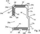
- Fig.3 shows a C-shaped cross-section along the line III-III of the profile rail piece 2 from Fig.1 .
- the C-shaped cross section of the profile rail piece 2 has a base 17 designed as a vertical wall with an inner side 18 and an outer side 19.
- a first guide profile 20a of the profile rail piece 2, in which the guide and support rollers can be moved, is accordingly located on a side facing the inner side 18.
- the base 17 also has a lower leg 21 and an upper leg 22, with a third leg 23 extending from the front of the upper leg 22 in a direction towards the lower leg 21.
- the lower leg 21 has a first hollow chamber H1, in which a counter-locking element 26 is arranged.
- the upper leg 22 has a second hollow chamber H2 and the third leg 23 has a third hollow chamber H3.
- the hollow chambers H1; H2; H3 and the counter-locking element 26 of the first profile rail piece 2 are designed as female receiving elements for the respective male plug-in and locking elements 7a; 7b; 8; 9 of the connecting piece 4 made of Fig. 2 provided.
- the hollow chambers H1; H2; H3 of the first profile rail piece 2 have rounded corners 24a; 24b; 24c; 24d; 24e; 24f and insertion bevels 25a; 25b; 25c.
- the insertion bevels 25a; 25b; 25c are each arranged at an entrance to a hollow chamber H1; H2; H3 and completely enclose a circumference of the respective hollow chamber H1; H2; H3, so that the plug-in and locking elements 7a; 7b; 8; 9 of the connecting piece 4 can be easily inserted into the corresponding hollow chambers H1; H2; H3 of the first profile rail piece 2.
- the counter-locking element 26, which is arranged in the lower leg 21 of the profile rail piece 2, is designed as an opening in which the locking lug 7b of the locking element 7a; 7b of the connecting piece 4 from Fig. 2 can engage in a form-fitting manner when the connecting piece 4 is plugged together with the profile rail piece 2.
- the base 17 comprises a step-like bevel 27, so that a lower region 17a of the base 17 and an upper region 17b of the base 17 are arranged offset from one another.
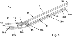
- Fig.4 shows one with the separate profile rail pieces 2; 3; 4 from Fig.1 composite profile rail 1.
- the profile rail 1 is designed for use in a door guide for a vehicle.
- the Fig.4 The profile rail 1 shown serves to guide support and guide means of a vehicle sliding door (not shown in detail here) and extends essentially axially along a main sliding direction of the vehicle sliding door.
- the first profile rail piece 2 and the second profile rail piece 3 each have at least one elongated hole 28a; 28b; 28c; 28d; 28e.
- force-locking and form-locking connecting means e.g.
- the profile rail 1 can be connected to a vehicle body.
- the guide elements 10; 15 of the connecting piece 4 which are arranged on the inner side 18 of the profile rail 1.
- the guide element 10 of the connecting piece 4 extends longitudinally with respect to the first profile rail piece 2 in a direction towards the second end face S2 of the first profile rail piece 2.
- the guide element 15 of the connecting piece 4 extends longitudinally with respect to the second profile rail piece 3 in a direction towards the second end face S4 of the second profile rail piece 3.
- the first profile rail piece 2 has a first guide profile 20a.
- the connecting piece 4 has a second guide profile 20b and the second profile rail piece 3 has a third guide profile 20c.
- the assembled profile rail 1 has a flush and aligned transition between the first profile rail piece 2 and the connecting piece 4 and between the second profile rail piece 3 and the connecting piece 4, so that the guide profiles 20a; 20b; 20c of the first profile rail piece 2, the second profile rail piece 3 and the connecting piece 4 form a unit, whereby the support and guide rollers can be displaced within the assembled profile rail 1 with little noise and with a high level of smoothness.
- the respective transitions of the profile rail 1 are designed to be almost gap-free and stepless.
- Fig.5 shows the assembled profile rail 1 from Fig.4 in a view from above.
- the connecting piece 4 has a curved section with an inner radius R
- the first profile rail piece 2 and the second profile rail piece 3 are arranged at an angle W to each other due to the connecting piece 4.
- the angle W is 120° here.
- the inner radius R of the connecting piece 4 in this embodiment is 65 millimeters, so that a rounded and even transition from the first profile rail piece 2 to the second profile rail piece 3 is ensured by the connecting piece 4.
- the outside 19 of the profile rail 1 is visible, so that the guide elements 11; 16 of the connecting piece 4 can be seen.
- the guide element 11 of the connecting piece 4 extends in the longitudinal direction with respect to the first profile rail piece 2 in a direction towards the second end face S2 of the first profile rail piece 2.
- the guide element 16 of the connecting piece 4 extends in the longitudinal direction with respect to the second profile rail piece 3 in a direction towards the second end face S4 of the second profile rail piece 3.
- Fig.6 shows a C-shaped cross-section along the line VI-VI of the profile rail piece 2 from Fig.5 .
- the guide elements 10; 11 of the connecting piece 4 are arranged in the longitudinal direction of the profile rail piece 2, each on the inside 18 and on the outside 19 of the base 17.
- the first guide element 10 of the connecting piece 4 is located on the inside 18 in the lower area 17a of the base 17.
- the second guide element 11 of the connecting piece 4 is located on the outside 19 in the upper area 17b of the base 17.
- this arrangement clamping the base 17 prevents undesired rotation of the connecting piece 4 with respect to the first profile rail piece 2.
- the locking lug 7b of the connecting piece 4 in the lower leg 21 of the first profile rail piece 2, which is in engagement with the counter-locking element 26, whereby the connecting piece 4 in the first profile rail piece 2.
- the second profile rail piece 3 has the same cross-sectional profile as the first profile rail piece 2, so that the second profile rail piece 3 can be plugged together with the connecting piece 4 at the second end 4b, which is formed symmetrically with respect to the first end 4a, via the connection region 6.
- the connecting piece 4 and the first profile rail piece 2 In order to form-fit the connecting piece 4 to the first profile rail piece 2, the connecting piece 4 and the first profile rail piece 2 must first be arranged butt to butt so that, for example, the first end 4a of the connecting piece 4 is aligned parallel to the first end face S1 of the first profile rail piece 2. Furthermore, the connecting piece 4 and the first profile rail piece 2 each have a C-shaped cross-section so that the first end 4a of the connecting piece 4 and the first end face S1 of the first profile rail piece are to be aligned congruently with respect to their C-shaped cross-section.
- plug-in and locking elements 7a; 7b; 8; 9 are to be aligned concentrically and coaxially with respect to the hollow chambers H1; H2; 3 of the first end face S1 of the first profile rail piece 2 so that the plug-in and locking elements 7a; 7b; 8; 9 fit into the respective hollow chambers H1; H2; H3, which are located within the front side S1.
- the locking element 7a with the locking lug 7b is assigned to the first hollow chamber H1 with the counter-locking element 26.
- the plug element 8 is assigned to the third hollow chamber H3 and the plug element 9 is assigned to the second hollow chamber H2.
- the guide profile 20a of the first profile rail piece 2 and the guide profile 20b of the connecting piece 4 are arranged parallel, aligned and flush with each other.
- the connecting piece 4 with its plug and locking elements 7a; 7b; 8; 9 can be inserted into the corresponding hollow chambers H1; H2; H3 of the first profile rail piece 2 and thus plugged together until the locking lug 7b of the Connecting piece 4 engages in the counter-locking element 26 in the lower leg 21. In this way, a force-fitting and form-fitting plug-in connection is created between the connecting piece 4 and the first profile rail piece 2.
- the counter-locking element 26 is arranged in the guide profile 20a of the first profile rail piece 2 in the lower leg 21. Furthermore, the counter-locking element 26 is designed as an opening in the lower leg 21 of the first profile rail piece 2, so that the locking lug 7b on its underside is freely accessible. By pressing on the underside of the locking lug 7b in a direction towards the upper leg 22 of the profile rail piece 2, the locking lug 7b can be moved to a position outside the counter-locking element 26 by moving the locking lug 7b upwards until the locking lug 7b is disengaged from the counter-locking element 26. If the locking lug 7b is located outside the counter-locking element 26, it is possible to separate the connecting piece 4 and the first profile rail piece 2 from one another by pulling them apart.
- the plug connection between the connecting piece 4 and the first profile rail piece 2 can be separated in a simple manner without the use of tools, so that the plug and locking elements 7a; 7b; 8; 9 of the connecting piece 4 can be pulled out of the respective hollow chambers H1; H2; H3 of the first profile rail piece 2.
- two separate profile rail pieces are obtained, namely the connecting piece 4 and the first profile rail piece 2.
- the curved connecting piece 4 which is made of plastic, is manufactured using an injection molding process, since the injection molding process allows any shape with any wall thickness to be produced economically and in large quantities.
- the material of the first profile rail piece 2 and the second profile rail piece 3 is an aluminum alloy, with the two straight profile rail pieces 2 and 3 being manufactured using an extrusion process.
- the use of aluminum alloys ensures the required load-bearing capacity and resilience of the door guide, so that even vehicle doors with a higher weight can be reliably used and put into operation.
- the profile rail 1 has a modular structure, in which any rail guides can be manufactured in a variety of ways thanks to a modular plug-in system.
- the modular structure of the profile rail 1 means that several curved or straight connecting pieces 4 can be plugged together with other profile rail pieces 2 and 3, since the respective end faces S1; S2; S3; S4 of the profile rail pieces 2 and 3 and the ends 4a; 4b as well as the connection areas 5; 6 of the connecting piece 4 are always coordinated with one another.
- S1; S2; S3; S4 of the profile rail pieces 2 and 3 and the ends 4a; 4b as well as the connection areas 5; 6 of the connecting piece 4 are always coordinated with one another.
- the advantage is that the required manufacturing and installation tolerances can always be adhered to, so that reproducible assembly on a vehicle is always possible.
- profile rail 1 for a door guide that are precisely coordinated with one another. Furthermore, this creates a basis for robot-assisted automation of the assembly. Finally, the profile rail 1 ensures low-noise operation and a long service life, which means that a corresponding door guide is characterized by very high quality.
- the plug connection technology of the profile rail 1 described above includes a first positive-locking plug connection component, which is created by the locking element 7a; 7b of the connecting piece 4 and the associated counter-locking element 26 of the first profile rail piece 2 as a result of an interlocking.
- the profile rail 1 further comprises a second non-positive plug connection component, in which the plug elements 8; 9, a first plug area of the locking element 7a and the guide elements 10; 11 of the connecting piece 4 frictionally and clampingly rest in the manner of a press fit in the lower area 17a and in the upper area 17b of the base 17 and in the hollow chambers H1; H2; H3 of the first profile rail piece 2.
- an alternative plug connection technology of the profile rail 1 could be carried out exclusively via non-positive locking, in that no locking elements are provided, so that disassembling the profile rail 1 into its individual parts 2; 3; 4 is even easier and faster.
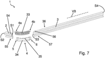
- Fig. 7 to Fig. 10 show a preferred second embodiment of the profile rail 1 according to the invention.
- the second embodiment of the profile rail 1 has several differences with respect to the first embodiment.
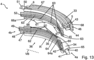
- Fig. 12 and Fig. 13 show that the connecting piece 4 curved with a radius R comprises an upper connecting piece part 33 and a lower connecting piece part 34, wherein the upper connecting piece part 33 and the lower connecting piece part 34 can be plugged together along a connecting line 35 to form a unit in a force-locking and form-locking manner by means of connecting line plug-in elements 60 and by means of connecting line locking elements 61.
- the upper connecting piece part 33 and the lower connecting piece part 34 are thus separate components which, when plugged together, form the connecting piece 4 according to Fig. 11 and Fig. 14
- the upper connector part 33 and the lower connector part 34 made of the same plastic material.
- Fig. 13 shows that the lower connecting piece part 34 has a total of five connecting line plug elements 60 designed as rectangular projections, wherein the upper connecting piece part 33 has complementary recesses 63, which are shown in dashed lines, into which the connecting line plug elements 60 can be inserted in a force-fitting manner.
- the lower connecting piece part 34 has an L-shaped cross section, wherein the L-shaped cross section comprises a first vertical leg 64 facing the vehicle body VB and a second horizontal leg 65 facing away from the vehicle body VB.
- the connecting line plug elements 60 are arranged on a horizontal surface 64a of the first vertical leg 64 of the lower connecting piece part 34, wherein the connecting line plug elements 60 extend in the longitudinal direction of the lower connecting piece part 34.
- the connecting line plug elements 60 have different lengths, so that the lower connecting piece part 34 has three long and two short connecting line plug elements 60, which follow the curvature of the radius R.
- the upper connecting piece part 33 has a U-shaped cross section rotated by 180°, wherein the U-shaped cross section comprises a first vertical leg 66 facing the vehicle body VB, a second horizontal leg 67 facing away from the vehicle body VB and a third vertical leg 68 extending from the second leg 67.
- recesses 63 are arranged on a horizontal surface 66a of the first vertical leg 66 of the upper connecting piece part 33, each of which is provided as a complementary receptacle for the connecting line plug elements 60 of the lower connecting piece part 34.
- four equally long vertical connecting line locking elements 61 protrude from the horizontal surface 66a of the first vertical leg 66 of the upper connecting piece part 33, which are arranged flush with a rear side of the first vertical leg 66 and which are adapted to the curvature of the radius R.
- Both the connecting line plug elements 60 and the connecting line locking elements 61 are arranged perpendicularly with respect to an extension direction of the upper connecting piece part 33 and the lower connecting piece part 34, respectively, wherein they face each other.
- the connecting line plug elements 60 of the lower connecting piece part 34 are arranged in alignment with the recesses 63 of the upper connecting piece part 33 and plugged into one another.
- the different lengths of the connecting line plug elements 60 or the complementary recesses 63 support the correct alignment and positioning of the upper connecting piece part 33 and the lower connecting piece part 34 during assembly.
- the four connecting line locking elements 61 designed as claws which are arranged on a side 36 of the lower connecting piece part 34 facing the vehicle body VB, engage or lock into an undercut 62 of the lower connecting piece part 34 designed as a rib.
- the upper connecting piece part 33 and the lower connecting piece part 34 are thus connected to one another in a force-fitting and form-fitting manner, whereby a stable connecting piece 4 is provided.
- Fig. 14 shows a front view of the assembled connector 4. It can be clearly seen that the front-side connecting line plug element 60 of the lower connector part 34 is arranged in the front-side recess 63 of the upper connector part 33, with an outwardly directed side of the front-side recess 63 being open. Furthermore, in connection with Fig. 12 It can be clearly seen that the guide elements 42; 45; 49; 52 and the plug-in elements 46; 53 of the upper connecting piece part 33 and the lower connecting piece part 34 are profiled. Furthermore, the locking lugs 41; 44; 48; 51 of the upper connecting piece part 33 and the lower connecting piece part 34 have different widths, whereby the stability of the connecting piece 4 within the assembled profile rail 1 is increased with regard to possible torsional forces.
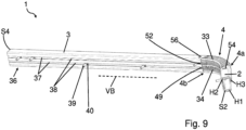
- first profile rail piece 2 and the second profile rail piece 3 now have an upper and a lower longitudinally formed hollow chamber 37, each with a slotted recess 38, on the side 36 facing the vehicle body VB of the vehicle, as in Fig.8 and in Fig.9 shown so that a head piece 40 of a threaded bolt 39 can be inserted into the hollow chamber 37 and can be displaced in the longitudinal direction of the first profile rail piece 2 or the second profile rail piece 3.
- the threaded bolt 39 thus protrudes away from the profile rail 1 in the direction of the vehicle body VB, wherein the head piece 40 of the threaded bolt 39 is arranged displaceably in the hollow chamber 37.
- Fig. 7 to Fig. 10 show that the first profile rail piece 2 has an upper counter-locking element 54 designed as a rectangular opening and an opposite lower counter-locking element 55 designed as a rectangular opening.
- the second profile rail piece 3 has an upper counter-locking element 54 designed as a rectangular opening.
- Counter-locking element 56 and an opposite lower counter-locking element 57 designed as a rectangular opening.
- Fig. 7 to Fig. 10 only the upper counter-locking elements 54; 56 of the first profile rail piece 2 or the second profile rail piece 3 are visible.
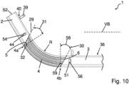
- first frontal connection area 5 of the connecting piece 4 is arranged in a first connection plane 29, which in Fig.10 and Fig. 11 can be seen, wherein the first connection plane 29 runs at a first angle 31 from a first normal plane 32.
- second opposite end connection region 6 of the connecting piece 4 is arranged in a second connection plane 30, wherein the second connection plane 30 runs at a second angle 58 from a second normal plane 59.
- Both the first normal plane 32 and the opposite second normal plane 59 are arranged perpendicular to an extension direction of the connecting piece 4.
- first frontal connection area 5 with the first connection level 29 and the second frontal connection area 6 with the second connection level 30 are arranged parallel to each other, which in Fig.10 can be seen in a view from above. Furthermore, both the first angle 31 and the second angle 58 are approximately 30°.
- Fig. 11 to Fig. 14 show that the first front-side connection region 5 of the upper connecting piece part 33 has an upper locking element 43 with a locking lug 44, an upper guide element 45 and a plug element 46, wherein the upper locking element 43 with the locking lug 44, the upper guide element 45 and the plug element 46 are arranged perpendicular to the first normal plane 32.
- the opposite second frontal connection area 6 of the upper connecting piece part 33 has an upper locking element 50 with a locking lug 51, an upper guide element 52 and a plug element 53, wherein the upper locking element 50 with the locking lug 51, the upper guide element 52 and the plug-in element 53 are arranged perpendicularly with respect to the second normal plane 59.
- the first front-side connection region 5 of the lower connecting piece part 34 has a lower locking element 40 with a locking lug 41 and a lower guide element 42, wherein the lower locking element 40 with the locking lug 41 and the lower guide element 42 are arranged perpendicular to the first normal plane 32.
- the opposite second front-side connection region 6 of the lower connecting piece part 34 has a lower locking element 47 with a locking lug 48 and a lower guide element 49, wherein the lower locking element 47 with the locking lug 48 and the lower guide element 49 are arranged perpendicular to the second normal plane 59.
- the respective locking lugs 41; 44; 48; 51 of the connecting piece 4 are engaged in the corresponding counter-locking elements 54; 55; 56; 57 of the two profile rail pieces 2; 3, wherein the first profile rail piece 2 and the second profile rail piece 3 each have complementary end faces S1; S2; S3; S4 with respect to the connecting piece 4 for flush and almost gap-free plugging together of the profile rail 1.
- Fig.9 that in an assembled state of the profile rail 1, the guide elements 49; 52 of the connecting piece 4 are arranged at least in sections in a lower and upper hollow chamber 37 of the second profile rail piece 3.
- the opposite guide elements 42; 45, not visible here, are arranged accordingly in the lower and upper hollow chamber 37 of the first profile rail piece 2.
Landscapes
- Engineering & Computer Science (AREA)
- Mechanical Engineering (AREA)
- Support Devices For Sliding Doors (AREA)
- Window Of Vehicle (AREA)
Abstract
Description
- Die Erfindung betrifft eine Profilschiene für eine Türführung eines Fahrzeuges.
- Aus der Praxis sind Türführungen für Fahrzeuge bekannt, die mit Schiebetüren für den Ein- und Ausstieg von Personen ausgestattet sind. Diese Schiebetüren werden oftmals mit geeigneten Führungs- bzw. Halteeinrichtungen in einer einteiligen Führungsschiene geführt, welche an der Fahrzeugkarosserie befestigt sind. Insbesondere ein gebogener Krümmungsabschnitt einer einteiligen Profilschiene bzw. Führungsschiene stellt Probleme für Führungsmittel, wie etwa Rollen eines Rollenwagens einer Tür dar, da sich Bereiche des Krümmungsabschnittes hinsichtlich der Herstellung, z. B. beim Streckbiegen der Profilschiene, einschnüren bzw. aufbiegen können, sodass bisher mit sehr hohen Fertigungstoleranzen gearbeitet werden musste, um einen einigermaßen reibungslosen Lauf der Führungsmittel, insbesondere im Krümmungsabschnitt der Profilschiene, gewährleisten zu können.
-
CN 108661476 B zeigt eine Profilschiene für eine Türführung eines Fahrzeuges, umfassend ein erstes Profilschienenstück mit einer ersten Stirnseite und mit einer zweiten Stirnseite sowie ein Verbindungsstück, wobei das Verbindungsstück ein erstes Ende und ein zweites Ende aufweist. Hierbei weist das erste Ende des Verbindungsstücks einen ersten stirnseitigen Anschlussbereich zum Stoß an Stoß Anordnen mit der ersten Stirnseite des ersten Profilschienenstücks auf, wobei das Profilschienenstück und das Verbindungsstück Langlöcher umfassen, sodass das Profilschienenstück und das Verbindungsstück über eine Schraubverbindung auf einer Oberfläche befestigbar sind. Alternativ sind das Profilschienenstück und das Verbindungsstück miteinander verschweißt. -
DE 10 2008 021 802 A1 zeigt eine Türführung eines Fahrzeuges mit einer entlang ihrer Längserstreckung zweigeteilten Profilschiene, die eine untere und eine obere Führungsschiene umfasst, wobei die untere und die obere Führungsschiene miteinander durch Vernieten verbunden sind. Die obere Führungsschiene der Profilschiene ist einerseits ein Tiefziehbauteil, und die untere Führungsschiene der Profilschiene ist andererseits ein Roll- und Streckbiegebauteil. In die Profilschiene sind Mittel zum Führen und zum Tragen einer Fahrzeugtür einsetzbar sowie entlang der Profilschiene verlagerbar. Nachteilig ist, dass die vorstehende Profilschiene zwar aus zumindest zwei zu verbindenden Bauteilen besteht, nämlich einer oberen Führungsschiene und einer unteren Führungsschiene. Im Endeffekt entspricht die zusammengesetzte Profilschiene einem einteiligen Bauteil, da diese entlang ihrer Längsrichtung zweigeteilt ist. Insbesondere gekrümmte Profilschienen, die einem Aufbau der vorstehenden Profilschiene entsprechen, können hohe Abmaße u. a. aufgrund der unterschiedlichen Fertigungsmethoden bezüglich der oberen und der unteren Führungsschiene aufweisen. Ferner können auch Wärmeausdehnungen und/oder Wärmeschrumpfungen durch Temperaturänderungen dazu führen, dass unerwünschte Abmaße hinsichtlich der zu montierenden Profilschiene auftreten. Infolgedessen ist es fertigungstechnisch schwierig, bestimmte Fertigungstoleranzen einzuhalten, wonach eine reproduzierbare Endmontage der Profilschiene an einem Fahrzeug deutlich erschwert wird, da die Profilschiene mit der Karosserie sowie mit weiteren Komponenten in nachfolgenden Montageschritten zusammengesetzt wird. Darüber hinaus besteht die Gefahr, dass zwischen den Führungsmitteln und der Profilschiene geforderte Einbautoleranzen nicht eingehalten werden können, sodass es während des Öffnens und/oder des Schließens einer Schiebetür zu einem unruhigen Lauf der Tür sowie zu störenden Geräuschen kommen kann. -
DE 20 2010 010 125 U1 zeigt eine Verbindung für zumindest zwei Profilschienenstücke. Die Verbindung umfasst ein erstes Profilschienenstück, ein zweites Profilschienenstück sowie ein aus Kunststoff hergestelltes Verbindungsstück. Um eine kraft- und formschlüssige Verbindung der beiden Profilschienenstücke zu gewährleisten, ist das Verbindungsstück mit dem ersten Profilschienenstück und mit dem zweiten Profilschienenstück verklebt. - Hierbei sind das erste Profilschienenstück und das zweite Profilschienenstück derart angeordnet, dass ein erster stirnseitiger Endbereich des ersten Profilschienenstücks und ein zweiter stirnseitiger Endbereich des zweiten Profilschienenstücks aneinanderstoßen. Des Weiteren weist das Verbindungsstück auf einer Unterseite eine Klebstoff-Beschichtung auf, die zusätzlich mit einer Abziehfolie ausgestattet ist. Für eine Verbindung der beiden Profilschienenstücke ist das Verbindungsstück sowohl klebend auf einer ersten Oberfläche des ersten Profilschienenstücks als auch klebend auf einer zweiten Oberfläche des zweiten Profilschienenstücks angeordnet.
-
US 2017 021 13 06 A1 zeigt eine einteilige Profilschiene für eine Türführung eines Fahrzeuges, umfassend ein erstes Profilschienenstück mit einer ersten Stirnseite und mit einer zweiten Stirnseite sowie ein Verbindungsstück, wobei das Verbindungsstück ein erstes Ende und ein zweites Ende aufweist. Hierbei ist das Verbindungsstück als ein Zwischenelement ausgebildet, um einen bestimmten Abstand zwischen einer Fahrzeugkarosserie und dem Profilschienenstück einzustellen. Hierbei ist das Verbindungsstück zwischen der Fahrzeugkarosserie und dem Profilschienenstück angeordnet. Ferner ist das Verbindungsstück im Wesentlichen parallel bezüglich des Profilschienenstückes ausgerichtet. -
DE 10 2009 033 136 A1 zeigt eine Profilschiene, wobei die Profilschiene Kunststoffbauteile umfasst, wobei die Kunststoffbauteile aus einem strahlenvernetzten Kunststoffmaterial hergestellt sind. - Es ist die Aufgabe der Erfindung, eine Profilschiene für eine Türführung eines Fahrzeuges zu schaffen, welche montagefreundlich und zuverlässig ist sowie einen geräuscharmen Betrieb ermöglicht.
- Diese Aufgabe wird erfindungsgemäß durch eine Profilschiene mit den Merkmalen des unabhängigen Anspruchs 1 gelöst.
- Gemäß der Erfindung ist eine Profilschiene für eine Türführung eines Fahrzeuges geschaffen, umfassend ein erstes Profilschienenstück mit einer ersten Stirnseite und mit einer zweiten Stirnseite, und ein Verbindungsstück, wobei das Verbindungsstück ein erstes Ende und ein zweites Ende aufweist, wobei das erste Ende des Verbindungsstücks einen ersten stirnseitigen Anschlussbereich zum Verbinden mit dem ersten Profilschienenstück aufweist, wobei das Verbindungsstück als ein separates Profilschienenstück ausgebildet ist, und wobei das Verbindungsstück über den ersten stirnseitigen Anschlussbereich mit zumindest einer Stirnseite des ersten Profilschienenstücks mittels eines Stecksystems verbindbar ist. Die Profilschiene zeichnet sich dadurch aus, dass das Verbindungsstück ein oberes Verbindungsstückteil und ein unteres Verbindungsstückteil umfasst, und dass das obere Verbindungsstückteil und das untere Verbindungsstückteil entlang einer bezüglich des ersten stirnseitigen Anschlussbereiches zumindest abschnittweise quer verlaufenden Verbindungslinie miteinander verbindbar sind. Vorteilhaft wird eine Flexibilität einer Montage mittels eines zweiteiligen Verbindungsstücks erhöht, um etwaige Fertigungstoleranzen auszugleichen.
- Gemäß einem Aspekt ist eine Profilschiene für eine Türführung eines Fahrzeuges geschaffen. Die Profilschiene umfasst ein erstes Profilschienenstück mit einer ersten Stirnseite und mit einer zweiten Stirnseite. Weiter umfasst die Profilschiene ein Verbindungsstück, welches ein erstes Ende und ein zweites Ende aufweist. Hierbei weist das erste Ende des Verbindungsstücks einen ersten stirnseitigen Anschlussbereich zum Verbinden mit dem ersten Profilschienenstück auf, wobei das Verbindungsstück als ein separates Profilschienenstück ausgebildet ist, und wobei das Verbindungsstück über den ersten stirnseitigen Anschlussbereich mit zumindest einer Stirnseite des ersten Profilschienenstücks mittels eines Stecksystems verbindbar ist. Ein Vorteil bezüglich einer Profilschiene, die mehrere miteinander verbundene Profilschienenstücke aufweist, liegt in der standardisierten Modulbauweise, sodass für jeden bestimmten Abschnitt der Profilschiene ein exakt definiertes Bauteil zum Einsatz kommt. Hierdurch wird stets eine hohe Qualität aufgrund der Einhaltung von Fertigungs- und Einbautoleranzen gewährleistet, wobei gleichzeitig eine erhöhte Flexibilität während einer Montage vorhanden ist. Die Profilschiene kann vorteilhaft hierfür maßgefertigte Einzelteile umfassen, die mittels eines intuitiven Stecksystems miteinander verbunden werden können, sodass eine Profilschiene mit einer bestimmten Länge und mit einem bestimmten Verlauf zur Verfügung gestellt werden kann. Vorteilhaft können bereits während der Montage etwaige Ungenauigkeiten, z. B. aufgrund von nicht eingehaltenen Fertigungstoleranzen oder möglichen thermischen Längenänderungen, ausgeglichen werden. Ferner ist es vorteilhaft möglich aufgrund eines Baukastensystems eine individuelle Profilschiene zügig und effizient herzustellen, sodass auch unterschiedliche Fahrzeuge mit individuellen Profilschienen für Türführungen bezüglich der Länge und des Verlaufs mittels der vorstehenden Profilschienenstücke ausgestattet werden können. Um die Montage zu vereinfachen, werden die einzelnen Profilschienenstücke intuitiv über ein Stecksystem miteinander verbunden. Vorteilhaft werden dadurch die Montagefreundlichkeit erhöht, der Bedarf an Werkzeug auf ein Minimum reduziert sowie enge Fertigungstoleranzen eingehalten. Ein Stecksystem bietet weiter den Vorteil, dass eine Profilschiene jederzeit wieder auseinandergebaut oder erweitert werden kann, um beispielsweise die Profilschiene bezüglich ihrer Länge und bezüglich ihres Verlaufs variabel anzupassen. Des Weiteren wird vorteilhaft Ausschussware durch Fehlproduktion einer Profilschiene vermieden, da die einzelnen standardisierten Profilschienenstücke lösbar verbindbar sind und dementsprechend in anderen Profilschienen zum Einsatz kommen. Ein weiterer Vorteil eines Stecksystems für eine Türführung ist, dass, falls ein Abschnitt der Profilschiene beschädigt ist, z. B. als Folge einer Kollision, nicht zwingend die ganze Profilschiene ausgetauscht werden muss, sondern es wird lediglich der defekte Abschnitt durch ein intaktes Profilschienenstück ersetzt.
- Gemäß einem Aspekt ist eine Profilschiene für eine Türführung eines Fahrzeuges geschaffen, umfassend ein erstes Profilschienenstück mit einer ersten Stirnseite und mit einer zweiten Stirnseite, und ein Verbindungsstück, wobei das Verbindungsstück ein erstes Ende und ein zweites Ende aufweist, wobei das erste Ende des Verbindungsstücks einen ersten stirnseitigen Anschlussbereich zum Verbinden mit dem ersten Profilschienenstück aufweist, wobei das Verbindungsstück als ein separates Profilschienenstück ausgebildet ist, und wobei das Verbindungsstück über den ersten stirnseitigen Anschlussbereich mit zumindest einer Stirnseite des ersten Profilschienenstücks mittels eines Stecksystems verbindbar ist, wobei der erste stirnseitige Anschlussbereich in einer ersten Anschlussebene angeordnet ist, die einen ersten Winkel zu einer ersten, zu einer Erstreckung des Verbindungsstücks normalen Ebene aufweist. Vorteilhaft verbessert ein schräger erster Anschlussbereich des Verbindungsstücks und eine komplementäre schräge erste Stirnseite des ersten Profilschienenstücks ein Zusammenstecken des Verbindungsstücks und des ersten Profilschienenstücks, da eine Kontaktierung zwischen dem ersten Anschlussbereich des Verbindungsstücks und der ersten Stirnseite des ersten Profilschienenstücks nahezu spaltfrei ist. Des Weiteren werden Laufrolleneigenschaften einer Tragrolle der Türführung vorteilhaft begünstigt, da die Tragrolle an einem Übergang von Verbindungsstück und erstes Profilschienenstück durch eine nahezu spaltfreie und stufenlose Ausführung des Übergangs ruckfrei und laufruhig verlagert wird, wobei eine Verlagerungsrichtung der Tragrolle unter einem Winkel kleiner 90° auf einen Spalt trifft.
- Gemäß einem Aspekt ist eine Profilschiene für eine Türführung eines Fahrzeuges geschaffen, umfassend ein erstes Profilschienenstück mit einer ersten Stirnseite und mit einer zweiten Stirnseite, und ein Verbindungsstück, wobei das Verbindungsstück ein erstes Ende und ein zweites Ende aufweist, wobei das erste Ende des Verbindungsstücks einen ersten stirnseitigen Anschlussbereich zum Verbinden mit dem ersten Profilschienenstück aufweist, wobei das Verbindungsstück als ein separates Profilschienenstück ausgebildet ist, und wobei das Verbindungsstück über den ersten stirnseitigen Anschlussbereich mit zumindest einer Stirnseite des ersten Profilschienenstücks mittels eines Stecksystems verbindbar ist, wobei das erste Profilschienenstück auf einer dem Fahrzeug zugekehrten Seite eine zumindest abschnittsweise durchgehende Hohlkammer aufweist, dass in der Hohlkammer eine Schlitzausnehmung ausgebildet ist, und dass ein Gewindebolzen mit einem Kopfstück in die Hohlkammer einsetzbar ist. Vorteilhaft ist die Profilschiene mittels eines verdeckten Verbindungsmittels an eine Fahrzeugkarosserie des Fahrzeugs anschließbar, sodass für einen Betrachter von außen keine störenden Elemente z.B. Schrauben erkennbar sind, und dass vorteilhaft eine mögliche Korrosionsquelle ausgeschaltet wird. Ein weiterer Vorteil ist, dass die Verbindungsmittel innerhalb der Hohlkammer verlagerbar sind, sodass eine Montage der Profilschiene an die Fahrzeugkarosserie vereinfacht wird, indem Fertigungstoleranzen mittels einer Verlagerung des Verbindungsmittels ausgeglichen werden können.
- Gemäß einem Aspekt ist eine Profilschiene für eine Türführung eines Fahrzeuges geschaffen, umfassend ein erstes Profilschienenstück mit einer ersten Stirnseite und mit einer zweiten Stirnseite, und ein Verbindungsstück, wobei das Verbindungsstück ein erstes Ende und ein zweites Ende aufweist, wobei das erste Ende des Verbindungsstücks einen ersten stirnseitigen Anschlussbereich zum Verbinden mit dem ersten Profilschienenstück aufweist, wobei das Verbindungsstück als ein separates Profilschienenstück ausgebildet ist, und wobei das Verbindungsstück über den ersten stirnseitigen Anschlussbereich mit zumindest einer Stirnseite des ersten Profilschienenstücks mittels eines Stecksystems verbindbar ist, wobei das Verbindungsstück zumindest ein Rastelement mit einer nachgiebigen, elastischen Rastnase aufweist, und dass die Rastnase des Verbindungsstücks mit einem als eine Ausnehmung ausgebildeten Gegenrastelement des ersten Profilschienenstücks ver- und entriegelbar ist. Vorteilhaft wird das Verbindungsstück einfach und schnell mit dem ersten Profilschienenstück zusammengesteckt, wobei eine sofortige Verriegelung erfolgt, wobei auf weitere Verbindungsmittel verzichtet werden kann, sodass eine Montage intuitiv, werkzeuglos und zügig erfolgt.
- Zweckmäßigerweise weist das erste Profilschienenstück auf einer dem Fahrzeug zugekehrten Seite eine zumindest abschnittsweise durchgehende Hohlkammer auf, wobei zweckmäßigerweise in der Hohlkammer eine Schlitzausnehmung ausgebildet ist, und wobei zweckmäßigerweise ein Gewindebolzen mit einem Kopfstück in die Hohlkammer einsetzbar ist.
- Vorteilhaft ist die Profilschiene mittels eines verdeckten Verbindungsmittels an eine Fahrzeugkarosserie des Fahrzeugs anschließbar, sodass für einen Betrachter von außen keine störenden Elemente z.B. Schrauben erkennbar sind, und dass vorteilhaft eine mögliche Korrosionsquelle ausgeschaltet wird. Ein weiterer Vorteil ist, dass die Verbindungsmittel innerhalb der Hohlkammer verlagerbar sind, sodass eine Montage der Profilschiene an die Fahrzeugkarosserie vereinfacht wird, indem Fertigungstoleranzen mittels einer Verlagerung des Verbindungsmittels ausgeglichen werden können. Alternativ sind der Gewindebolzen und das Kopfstück separat ausgebildet, wobei der Gewindebolzen und das Kopfstück miteinander z.B. über eine Schraubverbindung verbindbar sind. Ferner könnte der Gewindebolzen alternativ als ein Niet ausgebildet sein, um die Profilschiene über eine Nietverbindung an eine Fahrzeugkarosserie anzuschließen.
- Vorteilhafterweise weist die Schlitzausnehmung eine Breite auf, die etwas größer als ein Außendurchmesser des Gewindebolzens ist, sodass der Gewindebolzen aus der Schlitzausnehmung herausragt, und sodass der Gewindebolzen mit etwas Spiel entlang der Schlitzausnehmung verlagerbar ist.
- Zweckmäßigerweise erstrecken sich die Hohlkammer und die Schlitzausnehmung in Längsrichtung des ersten Profilschienenstücks. Hiermit ist vorteilhaft ein in die Hohlkammer eingesetztes Befestigungsmittel, z.B. ein Kopfstück mit einem aufgeschraubten Gewindebolzen oder eine Hammerkopfschraube, zuverlässig entlang des ersten Profilschienenstücks verlagerbar, wodurch eine Montagefreundlichkeit erhöht wird.
- Vorzugsweise ist der erste stirnseitige Anschlussbereich in einer ersten Anschlussebene angeordnet, die einen ersten Winkel zu einer ersten, zu einer Erstreckung des Verbindungsstücks normalen Ebene aufweist. Vorteilhaft verbessert ein schräger erster Anschlussbereich des Verbindungsstücks und eine komplementäre schräge erste Stirnseite des ersten Profilschienenstücks ein Zusammenstecken des Verbindungsstücks und des ersten Profilschienenstücks, da eine Kontaktierung zwischen dem ersten Anschlussbereich des Verbindungsstücks und der ersten Stirnseite des ersten Profilschienenstücks nahezu spaltfrei ist. Des Weiteren werden Laufrolleneigenschaften einer Tragrolle der Türführung vorteilhaft begünstigt, da die Tragrolle an einem Übergang von Verbindungsstück und erstes Profilschienenstück durch eine nahezu spaltfreie und stufenlose Ausführung des Übergangs ruckfrei und laufruhig verlagert wird, wobei eine Verlagerungsrichtung der Tragrolle unter einem Winkel kleiner 90° auf einen Spalt trifft.
- Zweckmäßigerweise verläuft die erste Anschlussebene unter einem ersten Winkel bezüglich der normalen Ebene des stirnseitigen Anschlussbereichs zwischen 20° und 70°, bevorzugt zwischen 25° und 35° und besonders bevorzugt zwischen 28° und 32°. Vorteilhaft konnte ermittelt werden, dass ein stirnseitiger Anschlussbereich unter einem Winkel von etwa 30° +/- 2° eine optimale Laufruhe und Leichtgängigkeit einer Tragrolle bei einer Verlagerung innerhalb der Profilschiene erzeugt.
- Gemäß einer besonders bevorzugten Ausführungsgestaltung ist vorgesehen, dass das zweite Ende des Verbindungsstücks einen zweiten stirnseitigen Anschlussbereich zum Verbinden mit einem zweiten Profilschienenstück aufweist, dass der zweite stirnseitige Anschlussbereich in einer zweiten Anschlussebene angeordnet ist, die einen zweiten Winkel zu einer zweiten, zu einer Erstreckung des Verbindungsstücks normalen Ebene aufweist, und dass die zweite Anschlussebene unter einem zweiten Winkel bezüglich der zweiten normalen Ebene des zweiten stirnseitigen Anschlussbereiches zwischen 20° und 70°, bevorzugt zwischen 25° und 35° und besonders bevorzugt zwischen 28° und 32° verläuft. Vorteilhaft verbessert ein schräger zweiter Anschlussbereich des Verbindungsstücks und eine komplementäre schräge erste Stirnseite des zweiten Profilschienenstücks ein Zusammenstecken des Verbindungsstücks und des zweiten Profilschienenstücks, da eine Kontaktierung zwischen dem zweiten Anschlussbereich des Verbindungsstücks und der ersten Stirnseite des zweiten Profilschienenstücks nahezu spaltfrei ist. Des Weiteren werden Laufrolleneigenschaften einer Tragrolle der Türführung vorteilhaft begünstigt, da die Tragrolle an einem Übergang von Verbindungsstück und zweites Profilschienenstück durch eine nahezu spaltfreie und stufenlose Ausführung des Übergangs ruckfrei und laufruhig verlagert wird, wobei eine Verlagerungsrichtung der Tragrolle unter einem Winkel kleiner 90° auf einen Spalt trifft. Darüber hinaus konnte vorteilhaft ermittelt werden, dass ein stirnseitiger Anschlussbereich unter einem Winkel von etwa 30° +/- 2° eine optimale Laufruhe und Leichtgängigkeit der Tragrolle bei einer Verlagerung innerhalb der Profilschiene erzeugt.
- Vorzugsweise erstreckt sich die erste Anschlussebene des ersten stirnseitigen Anschlussbereiches auf einer dem Fahrzeug zugewandten Seite fort von der ersten normalen Ebene in eine Richtung nach außen. Vorteilhaft wird eine Stabilität der Profilschiene auf diese Weise erhöht, wonach ein zuverlässiges Öffnen und Schließen einer Fahrzeugtür gewährleistet wird.
- Bevorzugt ist vorgesehen, dass die zweite Anschlussebene des zweiten stirnseitigen Anschlussbereiches auf einer dem Fahrzeug zugewandten Seite sich fort von der zweiten normalen Ebene in eine Richtung nach außen erstreckt. Vorteilhaft wird eine Stabilität der Profilschiene auf diese Weise erhöht, wonach ein zuverlässiges Öffnen und Schließen einer Fahrzeugtür gewährleistet wird.
- Bevorzugt ist vorgesehen, dass der erste stirnseitige Anschlussbereich als Steckelemente und/oder Rastelemente ausgebildete Vorsprünge aufweist, und dass die Steckelemente und die Rastelemente senkrecht bezüglich der ersten normalen Ebene angeordnet sind. Vorteilhaft wird ein intuitives Stecksystem zur Verfügung gestellt, wonach eine Montage zügig und werkzeuglos erfolgt.
- Zweckmäßigerweise weist der zweite stirnseitige Anschlussbereich als Steckelemente und/oder Rastelemente ausgebildete Vorsprünge auf, wobei die Steckelemente und die Rastelemente zweckmäßigerweise senkrecht bezüglich der zweiten normalen Ebene angeordnet sind. Vorteilhaft wird ein intuitives Stecksystem zur Verfügung gestellt, wonach eine Montage zügig und werkzeuglos erfolgt.
- Zweckmäßigerweise ist die erste Stirnseite und/oder die zweite Stirnseite des ersten Profilschienenstücks komplementär bezüglich des ersten stirnseitigen Anschlussbereiches des Verbindungsstücks ausgebildet. Vorteilhaft wird über komplementäre Anschlussflächen eine sehr gute Kontaktierung sichergestellt, wodurch die zusammengebaute Profilschiene eine bündige und spaltfreie Lauffläche bietet, sodass ein geräuscharmes und laufruhiges Verlagern einer Tragrolle ermöglicht wird.
- Gemäß einer bevorzugten Ausführungsform sind die erste Anschlussebene und die zweite Anschlussebene parallel. Vorteilhaft erhöht dies eine Montagefreundlichkeit, sodass ein Zusammenbau der Profilschiene intuitiv erfolgt.
- Besonders bevorzugt ist vorgesehen, dass das Verbindungsstück zumindest ein Rastelement mit einer nachgiebigen, elastischen Rastnase aufweist, und dass die Rastnase des Verbindungsstücks mit einem als eine Ausnehmung ausgebildeten Gegenrastelement des ersten Profilschienenstücks ver- und entriegelbar ist. Vorteilhaft wird das Verbindungsstück einfach und schnell mit dem ersten Profilschienenstück zusammengesteckt, wobei eine sofortige Verriegelung erfolgt, wobei auf weitere Verbindungsmittel verzichtet werden kann, sodass eine Montage intuitiv, werkzeuglos und zügig erfolgt.
- Gemäß einer besonders bevorzugten Ausführungsform ist vorgesehen, dass das obere Verbindungsstückteil eine obere Rastnase aufweist, und dass das untere Verbindungsstückteil eine untere Rastnase aufweist. Hiermit wird vorteilhaft eine Stabilität der zusammengebauten Profilschiene sichergestellt, indem auftretende Kräfte gleichmäßig sowohl aus dem oberen Verbindungsstückteil als auch aus dem unteren Verbindungsstückteil in das erste Profilschienenstück übertragen werden können. Ferner wird vorteilhaft ein werkzeugloses sowie intuitives Verriegelungssystem zur Verfügung gestellt.
- Vorzugsweise sind die obere Rastnase und die untere Rastnase parallel zueinander angeordnet, wobei die obere Rastnase und die untere Rastnase vorzugsweise abgekehrt voneinander angeordnet sind. Vorteilhaft können auf diese Weise in einem verrasteten Zustand Kräfte aus nahezu allen Richtungen aufgenommen und übertragen werden, sodass eine zuverlässige sowie stabile Profilschiene zur Verfügung gestellt wird.
- Zweckmäßigerweise sind das obere Verbindungsstückteil und das untere Verbindungsstückteil miteinander durch ein Stecken verbunden. Es wird vorteilhaft ein einfaches Stecksystem zur Verfügung gestellt, welches vorteilhaft eine Stabilität des zusammengebauten Verbindungsstücks gewährleistet. Ferner erfolgt ein Zusammenstecken vorteilhaft zügig und werkzeuglos.
- Gemäß einer bevorzugten Ausführungsform ist vorgesehen, dass das obere Verbindungsstückteil und das untere Verbindungsstückteil aus demselben Material hergestellt sind. Vorteilhaft weisen dieselben Materialien einen gleichen Wärmeausdehnungskoeffizienten auf, sodass eine temperaturbedingte Wärmeausdehnung keine unerwünschten Effekte erzeugt. Ferner liegen aufgrund derselben Materialauswahl vorteilhaft geringere Herstellkosten vor.
- Zweckmäßigerweise ist das Verbindungsstück aus einem Kunststoffmaterial hergestellt. Bei dem Kunststoffmaterial bezüglich des Verbindungsstücks kann es sich beispielsweise um ein Polyamid, Polyvinylchlorid, Polyoxymethylen oder Polypropylen etc. handeln, welches mittels eines Spritzgussverfahrens hergestellt ist. Dadurch, dass ein Kunststoff weitaus flexibler ist als ein Stahl- oder ein Aluminiummaterial, ist ein Verbindungsstück aus Kunststoff besonders leicht mit anderen Profilschienenstücken verbindbar, indem das Verbindungsstück in einem gewissen Umfang elastisch verformbar ist. Ferner lässt sich ein Verbindungsstück aus Kunststoff auch besonders gut plastisch deformieren. Dies ist beispielsweise bei einem möglichen nachfolgenden Fügeprozess, in dem z. B. ein Durchsetzfügeverfahren (sogenanntes Clinchen) zum Einsatz kommt, von Bedeutung. Aufgrund der geringeren Dichte eines Kunststoffes im Vergleich zu einem metallischen Bauteil wird das Gesamtgewicht einer Verbund-Profilschiene vorteilhaft reduziert. Ferner kann ein Verbindungsstück aus Kunststoff im Falle von thermischen Längenänderungen als ein Puffer dienen und somit etwaige Längenänderungen der metallischen Bauteile kompensieren. Ein weiterer Vorteil eines Verbindungsstücks aus einem Kunststoffmaterial ist eine hohe Korrosionsbeständigkeit. Darüber hinaus ist ein Betrieb einer Verbund-Profilschiene, bei der Kunststoffmaterialien zum Einsatz kommen, vorteilhaft geräuscharm, da Kunststoffe störende Geräusche absorbieren sowie mögliche Vibrationen dämpfen. Aufgrund der Herstellung des Verbindungsstücks mittels eines Spritzgussverfahrens können somit auch relativ komplizierte Formen bezüglich des Verbindungsstücks sowohl kostengünstig als auch in großen Mengen zügig produziert werden.
- Bevorzugt ist das erste Profilschienenstück aus einem metallischen Werkstoff hergestellt. Dadurch, dass das erste Profilschienenstück aus einem metallischen Werkstoff, z. B. aus einem Stahl oder einer Aluminiumlegierung, hergestellt ist, erhöht dies vorteilhaft die Tragfähigkeit sowie die Belastungsfähigkeit und somit auch die Lebensdauer der Türführung. Insbesondere geradlinige Profilschienenstücke werden bevorzugt mittels eines Strangpressverfahrens aus einer Aluminiumlegierung hergestellt. Bei einem Einsatz eines Stahls oder einer Aluminiumlegierung kann das jeweilige Profilschienenstück, um Verschleiß und Korrosion vorzubeugen, vor einer Endmontage an einer Fahrzeugkarosserie z. B. einem Anodisierungsverfahren oder einem Beschichtungsverfahren unterzogen werden.
- Gemäß einer alternativen bevorzugten Ausgestaltung ist das erste Profilschienenstück aus einem Kunststoffmaterial hergestellt. Bei dem Kunststoffmaterial bezüglich des ersten Profilschienenstücks sowie des Verbindungsstücks kann es sich beispielsweise um ein Polyamid, Polyvinylchlorid, Polyoxymethylen oder Polypropylen etc. handeln. Aufgrund der geringeren Dichte eines Kunststoffes im Vergleich zu einem metallischen Bauteil wird das Gesamtgewicht der Profilschiene vorteilhaft reduziert. Ferner können Material- und Produktionskosten deutlich reduziert werden, indem die gesamte Profilschiene aus Kunststoff zur Verfügung gestellt wird. Hierbei werden alle Profilschienenstücke inklusive des Verbindungsstücks mittels eines Spritzgussverfahrens kostengünstig hergestellt. Darüber hinaus ist ein Betrieb der aus Kunststoff hergestellten Profilschiene vorteilhaft geräuscharm, da Kunststoffe störende Geräusche absorbieren sowie mögliche Vibrationen dämpfen. Ferner weisen alle eingesetzten Profilschienenstücke, die aus dem gleichen Material hergestellt sind, die gleichen mechanischen, thermischen und chemischen Eigenschaften auf, sodass bei beispielsweise einer thermischen Längenänderung aufgrund der gleichen Wärmeausdehnungskoeffizienten die Profilschiene eine gleichmäßige thermische Expansion bzw. eine gleichmäßige thermische Kontraktion ausführt. Vorteilhaft können somit mögliche auftretende innere Spannungen innerhalb der zusammengesetzten Profilschiene minimiert werden, wodurch eine zuverlässige und geräuscharme Verlagerung von Trag- und Führungsrollen stets gewährleistet ist.
- Besonders bevorzugt ist das Kunststoffmaterial als strahlenvernetztes Kunststoffmaterial ausgebildet. Vorteilhaft können kostengünstige technische Kunststoffe mittels einer Strahlenvernetzung bezüglich ihrer mechanischen, thermischen sowie chemischen Eigenschaften derart verändert werden, dass diese den Eigenschaften von Hochleistungskunststoffen entsprechen. Strahlenvernetzte Kunststoffe weisen somit vorteilhaft eine erhöhte Tragfähigkeit sowie eine erhöhte Belastungsfähigkeit und somit auch eine erhöhte Lebensdauer der Türführung auf. Einerseits wird vorteilhaft infolge des eingesetzten Kunststoffmaterials das Gesamtgewicht der Profilschiene erheblich reduziert andererseits weist die Profilschiene mittels der Strahlenvernetzung vorteilhaft sehr gute mechanische, thermische und chemische Eigenschaften auf. Ferner können die einzelnen Profilschienenstücke und Verbindungsstücke mittels eines kostengünstigen Spritzgussverfahrens zügig und in hohen Mengen hergestellt werden.
- Zweckmäßigerweise weist das zweite Ende des Verbindungsstücks einen zweiten stirnseitigen Anschlussbereich zum Verbinden mit einem zweiten Profilschienenstück auf, wobei das zweite Profilschienenstück eine erste Stirnseite und eine zweite Stirnseite aufweist. Hierbei ist das Verbindungsstück über den zweiten stirnseitigen Anschlussbereich mit zumindest einer Stirnseite des zweiten Profilschienenstücks mittels eines Stecksystems verbindbar. Vorteilhaft kann das Verbindungsstück sowohl als ein Mittelteil zwischen zwei Profilschienenstücken als auch als ein Endstück einer Profilschiene zum Einsatz kommen. Dies erhöht sowohl die Funktionalität als auch die Montagefreundlichkeit bezüglich der Herstellung sowie bezüglich der Anwendung der Profilschiene. Dementsprechend kann das Verbindungsstück einen zweiten stirnseitigen Anschlussbereich aufweisen, der wiederum wie das erste Profilschienenstück mittels eines Stecksystems mit dem zweiten Profilschienenstück verbindbar ist. Das zweite Profilschienenstück kann entweder aus einem Stahl oder aus einer Aluminiumlegierung oder aus einem Kunststoffmaterial entsprechend dem ersten Profilschienenstück ausgebildet sein.
- Gemäß einer bevorzugten Ausgestaltung weist das Verbindungsstück zumindest einen gekrümmten Abschnitt mit zumindest einem Radius auf. Hierbei kommt vorteilhaft das Verbindungsstück als eine Art Eckverbinder oder als eine Art Winkelverbinder zum Einsatz, wodurch eine zusammengesetzte Profilschiene mittels der entsprechenden Profilschienenstücke über Eck oder zumindest abschnittsweise entlang einer gekrümmten Bahn verläuft. Ein als ein Eckverbinder ausgebildetes Verbindungsstück, das beispielsweise zumindest zwei Profilschienenstücke miteinander verbindet, weist vorteilhaft einen Winkel zwischen 90° und 150°, bevorzugt zwischen 140° und 100° und besonders bevorzugt zwischen 130° und 110° auf. Ein Innenradius des Verbindungsstücks beträgt bevorzugt zwischen 50 Millimeter und 100 Millimeter und besonders bevorzugt zwischen 60 Millimeter und 70 Millimeter, wodurch entsprechende Trag- und Führungsrollen der Türführung leichtgängig entlang einer gekrümmten Führungsbahn innerhalb des Verbindungsstücks verlagerbar sind. Das Verbindungsstück ist hierbei maßgeblich für den Winkel zwischen dem ersten Profilschienenstück und dem zweiten Profilschienenstück verantwortlich, sodass je nach Anwendungsfall individuelle Verbindungsstücke mit unterschiedlichen Winkeln und Radien zum Einsatz kommen können, wodurch eine sowohl montagefreundliche als auch eine flexible Baugruppe zur Verfügung gestellt wird, um eine individuelle Profilschiene zusammenzusetzen und diese schließlich an eine Fahrzeugkarosserie zu montieren. Vorteilhaft existieren somit geradlinige und gekrümmte Verbindungsstücke, um auch Profilschienen mit gekrümmten Abschnitten mittels eines Baukasten-Stecksystems schnell und effizient zur Verfügung zu stellen.
- Zweckmäßigerweise weisen das erste Profilschienenstück ein erstes Führungsprofil und das Verbindungsstück ein zweites Führungsprofil auf. Hierbei ist das erste Führungsprofil des ersten Profilschienenstücks und das zweite Führungsprofil des Verbindungsstücks in einem zusammengesetzten Zustand der Profilschiene jeweils fluchtend und bündig zueinander angeordnet, wodurch Mittel zum Führen und zum Tragen einer Fahrzeugtür entlang der zusammengesetzten Profilschiene verlagerbar sind. Damit entsprechende Trag- und Führungsrollen und/oder etwaige Gleitelemente, die Bestandteile der Türführung sind, innerhalb zumindest einer Führungsbahn der Profilschiene leichtgängig und geräuscharm verlagerbar sind, sind vorteilhaft die jeweiligen Führungsprofile bezüglich der einzelnen Profilschienenstücke bzw. Verbindungsstücke identisch ausgeführt. Des Weiteren sind die Übergänge zwischen den einzelnen Profilschienenstücken bzw. Verbindungsstücken in einem zusammengesetzten Zustand der Profilschiene stufenlos und nahezu spaltfrei ausgeführt. Dementsprechend sind die jeweiligen Führungsprofile oder zumindest die jeweiligen Führungsbahnen hinsichtlich des Verbindungsstücks und des zumindest einen Profilschienenstücks bündig und fluchtend sowie Stoß an Stoß zueinander ausgerichtet. Unter einer Führungsbahn sind die Bereiche des Führungsprofils zu verstehen, die bei einer Verlagerung der Fahrzeugtür durch die Führungs- und Tragrollen sowie durch weitere mögliche Gleitelemente kontaktiert werden. Ferner ist vorteilhaft die gesamte Führungsbahn des Führungsprofils der Profilschiene glatt ausgebildet. Vorteilhaft kann hierdurch eine Fahrzeugtür sehr leichtgängig, mit einer hohen Laufruhe sowie geräuscharm entweder händisch oder mittels eines Motors geöffnet bzw. geschlossen werden.
- Vorzugsweise weisen das erste Profilschienenstück und das Verbindungsstück jeweils einen C-förmigen Querschnitt auf. Vorteilhaft eignet sich ein C-förmiger Querschnitt besonders gut, um entsprechende Führungs- und Tragrollen in das Führungsprofil der Profilschiene einzusetzen sowie in dieser zuverlässig zu verlagern, ohne dass eine unerwünschte Entkopplung zwischen der Profilschiene und den Führungs- und Tragrollen stattfindet. Ferner ist eine Herstellung eines C-förmigen Bauteils z. B. mittels eines Spritzgussverfahrens für Kunststoffteile oder mittels eines Strangpressverfahrens für metallische Teile einfach sowie kostengünstig durchführbar, da insgesamt eine einfache Geometrie bezüglich der Profilschienenstücke bevorzugt wird. Darüber hinaus weist vorteilhaft ein C-förmiger Querschnitt eine sehr gute mechanische Stabilität auf, wodurch eine hohe Trag- und Belastungsfähigkeit der Profilschiene gewährleistet ist.
- Vorzugsweise steht von einem Schenkel der C-förmigen Profilschiene noch ein Schenkel in einem Winkel zwischen 80° und 135°, bevorzugt zwischen 90° und 110° und besonders bevorzugt zwischen 90° und 100° ab. Vorteilhaft dient der angewinkelte vorstehende Schenkel der C-förmigen Profilschiene als eine Art Widerlager, sodass ein seitliches Herausfallen oder Herausrutschen der Führungs- und Tragrollen aus der Profilschiene nicht möglich ist. Die Führungs- und Tragrollen werden somit stets innerhalb der für die Führungs- und Tragrollen vorgesehenen Führungsbahn zuverlässig in Position gehalten.
- Gemäß einer bevorzugten Ausgestaltung umfasst das Verbindungsstück zumindest ein Steckelement und zumindest ein Führungselement. Vorteilhaft weisen die entsprechenden Anschlussbereiche des Verbindungsstücks männliche Verbindungselemente für eine Steckverbindung mit Profilschienenstücken auf. Zu diesen Verbindungselementen zählen u. a. als vertikale Plättchen ausgebildete Führungs- und Haltehilfen, die jeweils stirnseitig von dem Verbindungsstück abstehen. Des Weiteren zählen zu den Verbindungselementen Steck- und Rastelemente, die jeweils stirnseitig von dem Verbindungsstück abstehen. Die Führungs- und Haltehilfen des Verbindungsstücks unterstützen eine fluchtende und bündige Ausrichtung mit einem weiteren Profilschienenstück in einem zusammengesetzten Zustand der Profilschiene. Ferner verhindern die Führungs- und Haltehilfen sowie die Steck- und Rastelemente vorteilhaft, dass das Verbindungsstück in einem zusammengesetzten Zustand der Profilschiene ein gewisses Spiel aufweist, sodass vorteilhaft das Verbindungsstück in irgendeine Richtung dessen Position bezüglich des angeschlossenen Profilschienenstücks nicht ändert. Darüber hinaus können die Steckelemente mit zumindest einer nachgiebigen, elastischen Rastnase ausgestattet sein, sodass das Verbindungsstück zumindest ein Rastelement aufweist. Eine Kombination aus Rast- und Steckelementen dient vorteilhaft einer stabilen kraftschlüssigen oder formschlüssigen Steckverbindung eines Verbindungsstücks mit einem weiteren Profilschienenstück. Hierbei handelt es sich bevorzugt um eine lösbare Steckverbindung mit engen Toleranzen, sodass das Verbindungsstück stramm mit dem Profilschienenstück verbunden ist. Um das Verbindungsstück an das Profilschienenstück anzuschließen, weist das Profilschienenstück bezüglich der männlichen Verbindungselemente des Verbindungsstücks bevorzugt korrespondierende weibliche Hohlkammerelemente auf. Des Weiteren weist das Profilschienenstück bevorzugt zumindest ein korrespondierendes Gegenrastelement auf, welches als eine Ausnehmung ausgebildet ist. In dem Gegenrastelement kann das elastische Rastelement bzw. die elastische Rastnase des Verbindungsstücks kraft- und formschlüssig einrasten. Vorteilhaft wird mittels der korrespondierenden männlichen und weiblichen Verbindungselemente ein einfaches, schnelles und intuitives Stecksystem für die Montage einer Profilschiene zur Verfügung gestellt, wobei kein zusätzliches Werkzeug benötigt wird.
- Alternativ kann das Verbindungsstück zumindest an einem Ende weibliche Hohlkammerelemente umfassen, wobei zumindest ein Hohlkammerelement zumindest ein Gegenrastelement aufweist. Das erste Profilschienenstück und das zweite Profilschienenstück können dementsprechend für eine Steckverbindung mit dem Verbindungsstück jeweils zumindest auf einer Stirnseite dazugehörige männliche Steck- und Rastelemente aufweisen.
- Vorzugsweise liegt in einem zusammengesetzten Zustand der Profilschiene das zumindest eine Führungselement des Verbindungsstücks in Längsrichtung des ersten Profilschienenstücks auf einer Innenseite des ersten Profilschienenstücks oder auf einer Außenseite des ersten Profilschienenstücks an. Hierbei kann vorteilhaft das Verbindungsstück in einem zusammengesetzten Zustand der Profilschiene insbesondere gegenüber möglich auftretenden Torsionskräften stabil in Position gehalten werden, sodass auch eine unerwünschte Verdrehung des Verbindungsstücks stets unterbunden ist. Insgesamt wird vorteilhaft mittels der vorstehenden Steck-, Rast- und Führungselemente das Verbindungsstück daran gehindert seine Position in irgendeine Richtung in einem zusammengesetzten Zustand der Profilschiene bezüglich des ersten Profilschienenstücks zu ändern. Ferner wird eine mögliche Torsionsverdrehung des Verbindungsstücks unterbunden, sodass die jeweiligen Führungsprofile bzw. Führungsbahnen stets fluchtend und bündig zueinander ausgerichtet sind, um ein leichtgängiges, laufruhiges und geräuscharmes Verlagern von Trag- und Führungsrollen innerhalb der gesamten Profilschiene zu gewährleisten.
- Weitere Vorteile, Eigenschaften, Merkmale und Weiterbildungen der beanspruchten Erfindung ergeben sich aus der nachfolgenden Beschreibung eines bevorzugten Ausführungsbeispiels sowie aus den abhängigen Ansprüchen.
- Die Erfindung wird nachstehend unter Bezugnahme auf die anliegenden Zeichnungen näher erläutert.
- Fig. 1
- zeigt eine perspektivische Explosionsansicht eines ersten Ausführungsbeispiels einer Profilschiene.
- Fig. 2
- zeigt eine perspektivische Ansicht eines gekrümmten Verbindungsstücks der Profilschiene aus
Fig. 1 . - Fig. 3
- zeigt einen Querschnitt entlang der Linie III-III des ersten Profilschienenstücks aus
Fig. 1 . - Fig. 4
- zeigt in einer perspektivischen Ansicht die Profilschiene aus
Fig. 1 in einem zusammengesetzten Zustand. - Fig. 5
- zeigt die Profilschiene aus
Fig. 4 in einer Ansicht von oben. - Fig. 6
- zeigt einen Querschnitt entlang der Linie VI-VI des ersten Profilschienenstücks aus
Fig. 5 . - Fig. 7
- zeigt eine perspektivische Explosionsansicht eines zweiten Ausführungsbeispiels der erfindungsgemäßen Profilschiene.
- Fig. 8
- zeigt eine perspektivische Rückansicht der Profilschiene aus
Fig. 7 . - Fig. 9
- zeigt eine zusammengesteckte Profilschiene aus
Fig. 8 . - Fig. 10
- zeigt eine Draufsicht eines Übergangsbereiches der zusammengesteckten Profilschiene aus
Fig. 9 . - Fig. 11
- zeigt eine perspektivische Ansicht eines gekrümmten zweiteiligen Verbindungsstücks in einem zusammengesteckten Zustand aus
Fig. 10 . - Fig. 12
- zeigt eine perspektivische Explosionsansicht des gekrümmten zweiteiligen Verbindungsstücks der Profilschiene aus
Fig. 11 . - Fig. 13
- zeigt eine perspektivische Rückansicht des gekrümmten zweiteiligen Verbindungsstücks der Profilschiene aus
Fig. 12 . - Fig. 14
- zeigt eine stirnseitige Vorderansicht Verbindungsstücks in einem zusammengesteckten Zustand aus
Fig. 13 . -
Fig. 1 zeigt in einer perspektivischen schematischen Ansicht einer Explosionsdarstellung ein erstes Ausführungsbeispiel für eine dreistückige Profilschiene 1, die ein erstes geradliniges Profilschienenstück 2, ein zweites geradliniges Profilschienenstück 3 und ein zwischen den beiden Profilschienenstücken 2 und 3 angeordnetes gekrümmtes Verbindungsstück 4 umfasst. Das Verbindungsstück 4 ist somit als ein drittes Profilschienenstück ausgebildet. Das erste Profilschienenstück 2 weist in eine Richtung zu dem Verbindungsstück 4 eine erste Stirnseite S1 auf, wobei das erste Profilschienenstück 2 in eine Richtung fort von dem Verbindungsstück 4 eine zweite Stirnseite S2 aufweist. Entsprechend dem ersten Profilschienenstück 2 weist das zweite Profilschienenstück 3 in eine Richtung zu dem Verbindungsstück 4 eine erste Stirnseite S3 auf, wobei das zweite - Profilschienenstück 3 in eine Richtung fort von dem Verbindungsstück 4 eine zweite Stirnseite S4 aufweist. Das abschnittsweise gekrümmte Verbindungsstück 4 umfasst ein erstes Ende 4a, welches der ersten Stirnseite S1 des ersten Profilschienenstücks 2 zugewandt ist, und ein zweites Ende 4b, welches der ersten Stirnseite S3 des zweiten Profilschienenstücks 3 zugewandt ist. Einerseits umfasst das erste Ende 4a des Verbindungsstücks 4 einen ersten stirnseitigen Anschlussbereich 5 zum Verbinden mit dem ersten Profilschienenstück 2 und andererseits umfasst das zweite Ende 4b des Verbindungsstücks 4 einen zweiten stirnseitigen Anschlussbereich 6 zum Verbinden mit dem zweiten Profilschienenstück 3. Das Verbindungsstück 4 ist symmetrisch bezüglich einer halbierenden Mittelebene E ausgebildet. Somit weisen der erste Anschlussbereich 5 und der zweite Anschlussbereich 6 vorteilhaft die gleiche bzw. eine spiegelsymmetrische Geometrie auf.
-
Fig. 2 zeigt in einer vergrößerten Ansicht das gekrümmte Verbindungsstück 4 mit einem Innenradius R ausFig. 1 , wobei der erste Anschlussbereich 5 ein erstes lineares Rastelement 7a mit einer ersten Rastnase 7b, ein erstes lineares Steckelement 8 und ein zweites lineares Steckelement 9 aufweist. Ferner enthält der erste Anschlussbereich 5 des Verbindungsstücks 4 ein erstes lineares Führungselement 10 und ein zweites lineares Führungselement 11, die jeweils als flächige dünnwandige Plättchen ausgebildet sind. Der zweite Anschlussbereich 6 des Verbindungsstücks 4 weist ein erstes lineares Rastelement 12a mit einer ersten Rastnase 12b, ein erstes lineares Steckelement 13 und ein zweites lineares Steckelement 14 auf. Ferner enthält der zweite Anschlussbereich 6 des Verbindungsstücks 4 ein erstes lineares Führungselement 15, welches inFig. 4 ersichtlich ist, und ein zweites lineares Führungselement 16, welches inFig. 5 ersichtlich ist. Die Führungselemente 10; 11; 15; 16 verhindern aufgrund ihrer Führungs- und Haltefunktion ein Verdrehen bzw. eine Positionsänderung in irgendeine Richtung des Verbindungsstücks 4 in einem zusammengesetzten Zustand der Profilschiene 1. Insgesamt ist das Verbindungsstück 4 mit dessen Rast- und Steckelementen 7a; 7b; 8; 9; 12a; 12b; 13; 14 sowie mit dessen Führungselementen 10; 11; 15; 16 einheitlich bzw. aus einem Guss ausgebildet. -
Fig. 3 zeigt einen C-förmigen Querschnitt entlang der Linie III-III des Profilschienenstücks 2 ausFig. 1 . Der C-förmige Querschnitt des Profilschienenstücks 2 weist eine als vertikale Wand ausgebildete Basis 17 mit einer Innenseite 18 und einer Außenseite 19 auf. Ein erstes Führungsprofil 20a des Profilschienenstücks 2, in dem die Führungs- und Tragrollen verlagerbar sind, befindet sich entsprechend auf einer der Innenseite 18 zugewandten Seite. Ferner weist die Basis 17 einen unteren Schenkel 21 und einen oberen Schenkel 22 auf, wobei von dem oberen Schenkel 22 stirnseitig ein dritter Schenkel 23 in eine Richtung zu dem unteren Schenkel 21 abgeht. Der untere Schenkel 21 weist eine erste Hohlkammer H1, in der ein Gegenrastelement 26 angeordnet ist, auf. Der obere Schenkel 22 weist eine zweite Hohlkammer H2 auf und der dritte Schenkel 23 weist eine dritte Hohlkammer H3 auf. Die Hohlkammern H1; H2; H3 sowie das Gegenrastelement 26 des ersten Profilschienenstücks 2 sind als weibliche Aufnahmeelemente für die jeweiligen männlichen Steck- und Rastelemente 7a; 7b; 8; 9 des Verbindungsstücks 4 ausFig. 2 vorgesehen. Ferner weisen die Hohlkammern H1; H2; H3 des ersten Profilschienenstücks 2 abgerundete Ecken 24a; 24b; 24c; 24d; 24e; 24f sowie Einführschrägen 25a; 25b; 25c auf. Die Einführschrägen 25a; 25b; 25c sind jeweils an einem Eintritt in eine Hohlkammer H1; H2; H3 angeordnet und umfassen vollständig einen Umfang der jeweiligen Hohlkammer H1; H2; H3, sodass die Steck- und Rastelemente 7a; 7b; 8; 9 des Verbindungsstücks 4 leichtgängig in die entsprechenden Hohlkammern H1; H2; H3 des ersten Profilschienenstücks 2 einführbar sind. Das Gegenrastelement 26, welches in dem unteren Schenkel 21 des Profilschienenstücks 2 angeordnet ist, ist als eine Durchbrechung ausgebildet, in dem die Rastnase 7b des Rastelements 7a; 7b des Verbindungsstücks 4 ausFig. 2 formschlüssig bei einem Zusammenstecken des Verbindungsstücks 4 mit dem Profilschienenstück 2 einrasten kann. Des Weiteren umfasst die Basis 17 eine stufenartige Abkantung 27, sodass ein unterer Bereich 17a der Basis 17 und ein oberer Bereich 17b der Basis 17 versetzt zueinander angeordnet sind. -
Fig. 4 zeigt eine mit den separaten Profilschienenstücken 2; 3; 4 ausFig. 1 zusammengesetzte Profilschiene 1. Die Profilschiene 1 ist für den Einsatz in einer Türführung für ein Fahrzeug ausgebildet. Die inFig. 4 gezeigte Profilschiene 1 dient zur Führung von hier nicht näher gezeigten Trag- und Führungsmitteln einer Fahrzeugschiebetür und erstreckt sich im Wesentlichen axial entlang einer Hauptschieberichtung der Fahrzeugschiebetür. Um die Profilschiene 1 an eine Fahrzeugkarosserie zu montieren, weisen das erste Profilschienenstück 2 und das zweite Profilschienenstück 3 jeweils zumindest eine Langlochbohrung 28a; 28b; 28c; 28d; 28e auf. Unter Zuhilfenahme von kraft- und formschlüssigen Verbindungsmitteln z. B. Schrauben, die die Langlochbohrungen 28a; 28b; 28c; 28d; 28e des ersten Profilschienenstücks 2 und des zweiten Profilschienenstücks 3 durchsetzen, kann die Profilschiene 1 an eine Fahrzeugkarosserie angeschlossen werden. Ferner zeigtFig. 4 die Führungselemente 10; 15 des Verbindungsstücks 4, die auf der Innenseite 18 der Profilschiene 1 angeordnet sind. Hierbei erstreckt sich das Führungselement 10 des Verbindungsstücks 4 in Längsrichtung bezüglich des ersten Profilschienenstücks 2 in eine Richtung zu der zweiten Stirnseite S2 des ersten Profilschienenstücks 2. Das Führungselement 15 des Verbindungsstücks 4 erstreckt sich in Längsrichtung bezüglich des zweiten Profilschienenstücks 3 in eine Richtung zu der zweiten Stirnseite S4 des zweiten Profilschienenstücks 3. Das erste Profilschienenstück 2 weist ein erstes Führungsprofil 20a auf. Das Verbindungsstück 4 weist ein zweites Führungsprofil 20b auf und das zweite Profilschienenstück 3 weist ein drittes Führungsprofil 20c auf. Damit entsprechende Trag- und Führungsrollen einwandfrei innerhalb der Führungsprofile 20a; 20b; 20c verlagerbar sind, weist die zusammengesetzte Profilschiene 1 zwischen dem ersten Profilschienenstück 2 und dem Verbindungsstück 4 und zwischen dem zweiten Profilschienenstück 3 und dem Verbindungsstück 4 einen bündigen und fluchtenden Übergang auf, sodass die Führungsprofile 20a; 20b; 20c des ersten Profilschienenstücks 2, des zweiten Profilschienenstücks 3 und des Verbindungsstücks 4 eine Einheit bilden, wodurch die Trag- und Führungsrollen innerhalb der zusammengesetzten Profilschiene 1 geräuscharm und mit einer hohen Laufruhe verlagerbar sind. Ferner sind die jeweiligen Übergänge der Profilschiene 1 nahezu spaltfrei sowie stufenlos ausgebildet. -
Fig. 5 zeigt die zusammengesetzte Profilschiene 1 ausFig. 4 in einer Ansicht von oben. Dadurch, dass das Verbindungsstück 4 einen gekrümmten Abschnitt mit einem Innenradius R aufweist, sind das erste Profilschienenstück 2 und das zweite Profilschienenstück 3 aufgrund des Verbindungsstücks 4 in einem Winkel W zueinander angeordnet. Der Winkel W beträgt hier 120°. Ferner beträgt der Innenradius R des Verbindungsstücks 4 in diesem Ausführungsbeispiel 65 Millimeter, sodass ein abgerundeter und gleichmäßiger Übergang von dem ersten Profilschienenstück 2 zu dem zweiten Profilschienenstück 3 durch das Verbindungsstück 4 gewährleistet ist. Ferner ist inFig. 5 die Außenseite 19 der Profilschiene 1 ersichtlich, sodass die Führungselemente 11; 16 des Verbindungsstücks 4 erkennbar sind. Hierbei erstreckt sich das Führungselement 11 des Verbindungsstücks 4 in Längsrichtung bezüglich des ersten Profilschienenstücks 2 in eine Richtung zu der zweiten Stirnseite S2 des ersten Profilschienenstücks 2. Das Führungselement 16 des Verbindungsstücks 4 erstreckt sich in Längsrichtung bezüglich des zweiten Profilschienenstücks 3 in eine Richtung zu der zweiten Stirnseite S4 des zweiten Profilschienenstücks 3. -
Fig. 6 zeigt einen C-förmigen Querschnitt entlang der Linie VI-VI des Profilschienenstücks 2 ausFig. 5 . In einem zusammengesteckten Zustand der Profilschiene 1 sind die Führungselemente 10; 11 des Verbindungsstücks 4 in Längsrichtung des Profilschienenstücks 2 jeweils auf der Innenseite 18 und auf der Außenseite 19 der Basis 17 anliegend angeordnet. Hierbei befindet sich das erste Führungselement 10 des Verbindungsstücks 4 auf der Innenseite 18 in dem unteren Bereich 17a der Basis 17. Das zweite Führungselement 11 des Verbindungsstücks 4 befindet sich auf der Außenseite 19 in dem oberen Bereich 17b der Basis 17. Infolgedessen wird aufgrund dieser die Basis 17 einklemmenden Anordnung eine unerwünschte Verdrehung des Verbindungsstücks 4 bezüglich des ersten Profilschienenstücks 2 unterbunden. Des Weiteren zeigtFig. 6 die Rastnase 7b des Verbindungsstücks 4 in dem unteren Schenkel 21 des ersten Profilschienenstücks 2, welche in Eingriff mit dem Gegenrastelement 26 steht, wodurch das Verbindungsstück 4 in dem ersten Profilschienenstück 2 festgelegt ist. - Das zweite Profilschienenstück 3 weist entsprechend dem ersten Profilschienenstück 2 das gleiche Querschnittsprofil auf, sodass das zweite Profilschienenstück 3 mit dem Verbindungsstück 4 an dem zweiten Ende 4b, welches symmetrisch bezüglich des ersten Endes 4a ausgebildet ist, über den Anschlussbereich 6 zusammensteckbar ist.
- Um das Verbindungsstück 4 mit dem ersten Profilschienenstück 2 formschlüssig zu verbinden, müssen das Verbindungsstück 4 und das erste Profilschienenstück 2 zunächst Stoß an Stoß angeordnet werden, sodass beispielsweise das erste Ende 4a des Verbindungsstücks 4 parallel zu der ersten Stirnseite S1 des ersten Profilschienenstücks 2 ausgerichtet ist. Des Weiteren weisen das Verbindungsstück 4 und das erste Profilschienenstück 2 jeweils einen C-förmigen Querschnitt auf, sodass das erste Ende 4a des Verbindungsstücks 4 und die erste Stirnseite S1 des ersten Profilschienenstücks kongruent bezüglich ihres C-förmigen Querschnitts auszurichten sind. Hierbei ist weiter zu beachten, dass die Steck- und Rastelemente 7a; 7b; 8; 9 bezüglich der Hohlkammern H1; H2; 3 der ersten Stirnseite S1 des ersten Profilschienenstücks 2 jeweils konzentrisch sowie koaxial auszurichten sind, sodass die Steck- und Rastelemente 7a; 7b; 8; 9 in die jeweiligen Hohlkammern H1; H2; H3, die sich innerhalb der Stirnseite S1 befinden, einführbar sind. Das Rastelement 7a mit der Rastnase 7b ist der ersten Hohlkammer H1 mit dem Gegenrastelement 26 zugeordnet. Das Steckelement 8 ist der dritten Hohlkammer H3 zugeordnet und das Steckelement 9 ist der zweiten Hohlkammer H2 zugeordnet. Ferner ist zu beachten, dass das Führungsprofil 20a des ersten Profilschienenstücks 2 und das Führungsprofil 20b des Verbindungsstücks 4 parallel, fluchtend und bündig zueinander angeordnet sind. Sobald die entsprechende Ausrichtung des ersten Profilschienenstücks 2 und des Verbindungsstücks 4 ausgeführt ist, kann das Verbindungsstück 4 mit dessen Steck- und Rastelementen 7a; 7b; 8; 9 in die korrespondierenden Hohlkammern H1; H2; H3 des ersten Profilschienenstücks 2 eingeführt und somit zusammengesteckt werden, bis die Rastnase 7b des Verbindungsstücks 4 in das Gegenrastelement 26 in dem unteren Schenkel 21 einrastet. Auf diese Weise ist eine kraft- und formschlüssige Steckverbindung zwischen dem Verbindungsstück 4 und dem ersten Profilschienenstück 2 entstanden. Das Gegenrastelement 26 ist in dem Führungsprofil 20a des ersten Profilschienenstücks 2 in dem unteren Schenkel 21 angeordnet. Ferner ist das Gegenrastelement 26 als eine Durchbrechung in dem unteren Schenkel 21 des ersten Profilschienenstücks 2 ausgebildet, sodass die Rastnase 7b an dessen Unterseite frei zugänglich ist. Durch ein Drücken auf die Unterseite der Rastnase 7b in eine Richtung zu dem oberen Schenkel 22 des Profilschienenstücks 2 kann die Rastnase 7b in eine Position außerhalb des Gegenrastelements 26 verlagert werden, indem die Rastnase 7b so weit nach oben verlagert wird, bis die Rastnase 7b außer Eingriff mit dem Gegenrastelement 26 steht. Insofern sich die Rastnase 7b außerhalb des Gegenrastelements 26 befindet, ist es möglich das Verbindungsstück 4 und das erste Profilschienenstück 2 durch ein Auseinanderziehen voneinander zu trennen. Hierbei kann die Steckverbindung zwischen dem Verbindungsstück 4 und dem ersten Profilschienenstück 2 auf eine einfache Art und Weise ohne einen Werkzeugeinsatz getrennt werden, sodass die Steck- und Rastelemente 7a; 7b; 8; 9 des Verbindungsstücks 4 aus den jeweiligen Hohlkammern H1; H2; H3 des ersten Profilschienenstücks 2 herausgezogen werden können. Infolgedessen erhält man wiederum zwei separate Profilschienenstücke, nämlich das Verbindungsstück 4 und das erste Profilschienenstück 2.
- Um das zweite Profilschienenstück 3 an das zweite Ende 4b des Verbindungsstücks 4 anzuschließen werden die vorstehenden Schritte entsprechend dem Anschluss des ersten Profilschienenstücks 2 ausgeführt. Ein Trennen der Verbindung zwischen dem Verbindungsstück 4 und dem zweiten Profilschienenstück 3 wird ebenfalls entsprechend dem ersten Profilschienenstück 2 wie vorstehend beschrieben ausgeführt. Indem das erste Profilschienenstück 2 und das zweite Profilschienenstück 3 mit dem Verbindungsstück 4 verbunden werden, wird auf diese Weise eine Profilschiene 1, die in
Fig. 4 gezeigt ist, zusammengesetzt und somit für einen Einsatz in einer Türführung eines Fahrzeuges zur Verfügung gestellt. - Eine Herstellung des gekrümmten Verbindungsstücks 4, welches aus einem Kunststoff besteht, erfolgt mittels eines Spritzgussverfahrens, da durch das Spritzgussverfahren beliebige Formen mit beliebigen Wandstärken wirtschaftlich sowie in einer hohen Menge herstellbar sind. Das Material des ersten Profilschienenstücks 2 und des zweiten Profilschienenstücks 3 ist eine Aluminiumlegierung, wobei die beiden geradlinigen Profilschienenstücke 2 und 3 mittels eines Strangpressverfahrens hergestellt werden. Durch den Einsatz von Aluminiumlegierungen ist eine erforderliche Tragfähigkeit sowie Belastbarkeit der Türführung sichergestellt, sodass auch Fahrzeugtüren mit einem erhöhten Gewicht zuverlässig eingesetzt und in Betrieb genommen werden können.
- Insgesamt weist die Profilschiene 1 einen modulartigen Aufbau auf, indem infolge eines Baukasten-Stecksystems beliebige Schienenführungen vielseitig herstellbar sind. Durch den modulartigen Aufbau der Profilschiene 1 können mehrere gekrümmte oder geradlinige Verbindungsstücke 4 mit weiteren Profilschienenstücken 2 und 3 zusammengesteckt werden, da die jeweiligen Stirnseiten S1; S2; S3; S4 der Profilschienenstücke 2 und 3 und die Enden 4a; 4b sowie die Anschlussbereiche 5; 6 des Verbindungsstücks 4 stets aufeinander abgestimmt sind. Infolgedessen ist es möglich, beliebige individuelle Führungsbahnen einer Profilschiene 1 zusammenzusetzen. Der Vorteil ist, dass geforderte Fertigungs- und Einbautoleranzen stets eingehalten werden können, sodass stets eine reproduzierbare Montage an einem Fahrzeug ermöglicht wird. Hiermit sind standardisierte Einzelbauteile einer Profilschiene 1 für eine Türführung geschaffen, die exakt aufeinander abgestimmt sind. Ferner ist somit eine Grundlage für eine robotergestützte Automation des Zusammenbaus geschaffen. Die Profilschiene 1 gewährleistet schließlich einen geräuscharmen Betrieb sowie eine lange Lebensdauer, wonach sich eine entsprechende Türführung durch eine sehr hohe Qualität auszeichnet.
- Die vorstehend erläuterte Steckverbindungstechnik der Profilschiene 1 umfasst eine erste formschlüssige Steckverbindungskomponente, welche durch das Rastelement 7a; 7b des Verbindungsstücks 4 und des dazugehörigen Gegenrastelements 26 des ersten Profilschienenstücks 2 infolge eines Ineinandergreifens entsteht. Die Profilschiene 1 umfasst weiter eine zweite kraftschlüssige Steckverbindungskomponente, indem die Steckelemente 8; 9, ein erster Steckbereich des Rastelements 7a sowie die Führungselemente 10; 11 des Verbindungsstücks 4 reibend und klemmend in der Art einer Presspassung entsprechend in dem unteren Bereich 17a sowie in dem oberen Bereich 17b der Basis 17 und in den Hohlkammern H1; H2; H3 des ersten Profilschienenstücks 2 anliegen. Ferner könnte eine alternative Steckverbindungstechnik der Profilschiene 1 ausschließlich über Kraftschluss erfolgen, indem keine Rastelemente vorgesehen sind, sodass ein Auseinanderbauen der Profilschiene 1 in deren Einzelteile 2; 3; 4 noch einfacher und schneller durchführbar ist.
-
Fig. 7 bis Fig. 10 zeigen ein bevorzugtes zweites Ausführungsbeispiel der erfindungsgemäßen Profilschiene 1. Hierbei weist das zweite Ausführungsbeispiel der Profilschiene 1 mehrere Unterschiede bezüglich des ersten Ausführungsbeispiels auf. - Ein Unterschied ist, dass das Verbindungsstück 4, welches u.a. in
Fig. 11 bis Fig. 14 vergrößert dargestellt ist, nunmehr aus zwei Teilstücken zusammengesetzt ist. -
Fig. 12 undFig. 13 zeigen, dass das mit einem Radius R gekrümmte Verbindungsstück 4 ein oberes Verbindungsstückteil 33 und ein unteres Verbindungsstückteil 34 umfasst, wobei das obere Verbindungsstückteil 33 und das untere Verbindungsstückteil 34 entlang einer Verbindungslinie 35 zu einer Einheit kraft- und formschlüssig mittels Verbindungslinien-Steckelementen 60 sowie mittels Verbindungslinien-Rastelementen 61 zusammensteckbar sind. Das obere Verbindungsstückteil 33 und das untere Verbindungsstückteil 34 sind somit separate Bauteile, die in einem zusammengesteckten Zustand das Verbindungsstück 4 gemäßFig. 11 undFig. 14 ausbilden. Ferner bestehen das obere Verbindungsstückteil 33 und das untere Verbindungsstückteil 34 aus demselben Kunststoffmaterial. -
Fig. 13 zeigt, dass das untere Verbindungsstückteil 34 insgesamt fünf als rechteckförmige Vorsprünge ausgebildete Verbindungslinien-Steckelemente 60 aufweist, wobei das obere Verbindungsstückteil 33 komplementäre Aussparungen 63 aufweist, die gestrichelt dargestellt sind, in denen die Verbindungslinien-Steckelemente 60 kraftschlüssig einsteckbar sind. - Hierbei weist das untere Verbindungsstückteil 34 einen L-förmigen Querschnitt auf, wobei der L-förmige Querschnitt einen der Fahrzeugkarosserie VB zugewandten ersten vertikalen Schenkel 64 und einen von der Fahrzeugkarosserie VB abgekehrten zweiten horizontalen Schenkel 65 umfasst. Die Verbindungslinien-Steckelemente 60 sind auf einer horizontalen Oberfläche 64a des ersten vertikalen Schenkels 64 des unteren Verbindungsstückteils 34 angeordnet, wobei die Verbindungslinien-Steckelemente 60 sich in Längsrichtung des unteren Verbindungsstückteils 34 erstrecken. Ferner weisen die Verbindungslinien-Steckelemente 60 unterschiedliche Längen auf, sodass das untere Verbindungsstückteil 34 drei lange und zwei kurze Verbindungslinien-Steckelemente 60 aufweist, welche der Krümmung des Radius R folgen.
- Das obere Verbindungsstückteil 33 weist einen um 180° gedrehten U-förmigen Querschnitt auf, wobei der U-förmige Querschnitt einen der Fahrzeugkarosserie VB zugewandten ersten vertikalen Schenkel 66, einen von der Fahrzeugkarosserie VB abgekehrten zweiten horizontalen Schenkel 67 und einen von dem zweiten Schenkel 67 abgehenden dritten vertikalen Schenkel 68 umfasst. Hierbei sind auf einer horizontalen Oberfläche 66a des ersten vertikalen Schenkels 66 des oberen Verbindungsstückteils 33 Aussparungen 63 angeordnet, die jeweils als eine komplementäre Aufnahme für die Verbindungslinien-Steckelemente 60 des unteren Verbindungsstückteils 34 vorgesehen sind.
- Ferner stehen von der horizontalen Oberfläche 66a des ersten vertikalen Schenkels 66 des oberen Verbindungsstückteils 33 vier gleich lange vertikale Verbindungslinien-Rastelemente 61 vor, die bündig mit einer Rückseite des ersten vertikalen Schenkels 66 angeordnet sind, und die an die Krümmung des Radius R angepasst sind.
- Sowohl die Verbindungslinien-Steckelemente 60 als auch die Verbindungslinien-Rastelemente 61 sind senkrecht bezüglich einer Erstreckungsrichtung des oberen Verbindungsstückteils 33 bzw. des unteren Verbindungsstückteils 34 angeordnet, wobei diese zueinander zugewandt sind.
- Um das obere Verbindungsstückteil 33 mit dem unteren Verbindungsstückteil 34 zusammenzustecken, werden die Verbindungslinien-Steckelemente 60 des unteren Verbindungsstückteils 34 fluchtend mit den Aussparungen 63 des oberen Verbindungsstückteils 33 angeordnet und ineinandergesteckt. Die unterschiedlichen Längen der Verbindungslinien-Steckelemente 60 bzw. der komplementären Aussparungen 63 unterstützen bei einer Montage die korrekte Ausrichtung sowie Positionierung des oberen Verbindungsstückteils 33 und des unteren Verbindungsstückteils 34. Darüber hinaus hintergreifen bzw. verrasten die vier als Klauen ausgebildete Verbindungslinien-Rastelemente 61, welche auf einer der Fahrzeugkarosserie VB zugewandten Seite 36 des unteren Verbindungsstückteils 34 angeordnet sind, eine als Rippe ausgebildete Hinterschneidung 62 des unteren Verbindungsstückteils 34. Somit sind das obere Verbindungsstückteil 33 und das untere Verbindungsstückteil 34 kraft- und formschlüssig miteinander verbunden, wodurch ein stabiles Verbindungsstück 4 zur Verfügung gestellt wird.
-
Fig. 14 zeigt eine Vorderansicht des zusammengesetzten Verbindungsstücks 4. Es ist gut zu erkennen, dass das stirnseitige Verbindungslinien-Steckelement 60 des unteren Verbindungsstückteils 34 in der stirnseitigen Aussparung 63 des oberen Verbindungsstückteils 33 angeordnet ist, wobei eine nach außen gerichtete Seite der stirnseitigen Aussparung 63 offen ist. Des Weiteren ist in Verbindung mitFig. 12 gut zu erkennen, dass die Führungselemente 42; 45; 49; 52 sowie die Steckelemente 46; 53 des oberen Verbindungsstückteils 33 und des unteren Verbindungsstückteils 34 profiliert ausgebildet sind. Ferner weisen die Rastnasen 41; 44; 48; 51 des oberen Verbindungsstückteils 33 und des unteren Verbindungsstückteils 34 unterschiedliche Breiten auf, wodurch die Stabilität des Verbindungsstücks 4 innerhalb der zusammengesteckten Profilschiene 1 hinsichtlich etwaiger Torsionskräfte erhöht wird. - Ein weiterer Unterschied ist, dass nunmehr das erste Profilschienenstück 2 und das zweite Profilschienenstück 3 auf der der Fahrzeugkarosserie VB des Fahrzeugs zugewandten Seite 36 eine obere und eine untere in Längsrichtung ausgebildete Hohlkammer 37 mit jeweils einer Schlitzausnehmung 38 aufweisen, so wie in
Fig. 8 und inFig. 9 gezeigt, sodass ein Kopfstück 40 eines Gewindebolzens 39 in der Hohlkammer 37 einsetzbar sowie in Längsrichtung des ersten Profilschienenstücks 2 bzw. des zweiten Profilschienenstücks 3 verlagerbar ist. Der Gewindebolzen 39 steht somit fort von der Profilschiene 1 in Richtung zu der Fahrzeugkarosserie VB ab, wobei das Kopfstück 40 des Gewindebolzens 39 in der Hohlkammer 37 verschieblich angeordnet ist. - Hiermit wird vorteilhaft die Flexibilität der mit dem Fahrzeug zu montierenden Profilschiene 1 erhöht, indem die Position des Gewindebolzens 39 in Längsrichtung des ersten Profilschienenstücks 2 bzw. des zweiten Profilschienenstücks 3 geführt anpassbar ist, wonach Fertigungstoleranzen einfach durch ein geführtes Verschieben des Gewindebolzens 39 innerhalb der Hohlkammer 37 ausgeglichen werden können. Ferner sind Befestigungselemente zur Befestigung der Profilschiene 1 mit der Fahrzeugkarosserie VB für eine Person von außen nicht sichtbar und es wird vorteilhaft eine Korrosionsquelle eliminiert.
-
Fig. 7 bis Fig. 10 zeigen, dass das erste Profilschienenstück 2 ein als eine rechteckige Durchbrechung ausgebildetes oberes Gegenrastelement 54 und ein gegenüberliegendes als eine rechteckige Durchbrechung ausgebildetes unteres Gegenrastelement 55 aufweist. Das zweite Profilschienenstück 3 weist ein als eine rechteckige Durchbrechung ausgebildetes oberes Gegenrastelement 56 und ein gegenüberliegendes als eine rechteckige Durchbrechung ausgebildetes unteres Gegenrastelement 57 auf. Hierbei sind inFig. 7 bis Fig. 10 lediglich die oberen Gegenrastelemente 54; 56 des ersten Profilschienenstücks 2 bzw. des zweiten Profilschienenstücks 3 erkennbar. - Ein weiterer Unterschied ist, dass der erste stirnseitige Anschlussbereich 5 des Verbindungsstücks 4 in einer ersten Anschlussebene 29 angeordnet ist, was in
Fig. 10 undFig. 11 erkennbar ist, wobei die erste Anschlussebene 29 unter einem ersten Winkel 31 von einer ersten normalen Ebene 32 verläuft. Ferner ist der zweite gegenüberliegende stirnseitige Anschlussbereich 6 des Verbindungsstücks 4 in einer zweiten Anschlussebene 30 angeordnet, wobei die zweite Anschlussebene 30 unter einem zweiten Winkel 58 von einer zweiten normalen Ebene 59 verläuft. Sowohl die erste normale Ebene 32 als auch die gegenüberliegende zweite normale Ebene 59 sind senkrecht zu einer Erstreckungsrichtung des Verbindungsstücks 4 angeordnet. - Des Weiteren sind der erste stirnseitige Anschlussbereich 5 mit der ersten Anschlussebene 29 und der zweite stirnseitige Anschlussbereich 6 mit der zweiten Anschlussebene 30 parallel zueinander angeordnet, was in
Fig. 10 in einer Ansicht von oben erkennbar ist. Ferner beträgt sowohl der erste Winkel 31 als auch der zweite Winkel 58 etwa 30°. -
Fig. 11 bis Fig. 14 zeigen, dass der erste stirnseitige Anschlussbereich 5 des oberen Verbindungsstückteils 33 ein oberes Rastelement 43 mit einer Rastnase 44, ein oberes Führungselement 45 sowie ein Steckelement 46 aufweist, wobei das obere Rastelement 43 mit der Rastnase 44, das obere Führungselement 45 sowie das Steckelement 46 senkrecht bezüglich der ersten normalen Ebene 32 angeordnet sind. - Der gegenüberliegende zweite stirnseitige Anschlussbereich 6 des oberen Verbindungsstückteils 33 weist ein oberes Rastelement 50 mit einer Rastnase 51, ein oberes Führungselement 52 sowie ein Steckelement 53 auf, wobei das obere Rastelement 50 mit der Rastnase 51, das obere Führungselement 52 sowie das Steckelement 53 senkrecht bezüglich der zweiten normalen Ebene 59 angeordnet sind.
- Ferner weist der erste stirnseitige Anschlussbereich 5 des unteren Verbindungsstückteils 34 ein unteres Rastelement 40 mit einer Rastnase 41 und ein unteres Führungselement 42 auf, wobei das untere Rastelement 40 mit der Rastnase 41 und das untere Führungselement 42 senkrecht bezüglich der ersten normalen Ebene 32 angeordnet sind.
- Der gegenüberliegende zweite stirnseitige Anschlussbereich 6 des unteren Verbindungsstückteils 34 weist ein unteres Rastelement 47 mit einer Rastnase 48 und ein unteres Führungselement 49 auf, wobei das untere Rastelement 47 mit der Rastnase 48 und das untere Führungselement 49 senkrecht bezüglich der zweiten normalen Ebene 59 angeordnet sind.
- Infolgedessen sind in einem zusammengesetzten Zustand der Profilschiene 1 die jeweiligen Rastnasen 41; 44; 48; 51 des Verbindungsstücks 4 in den entsprechenden Gegenrastelementen 54; 55; 56; 57 der beiden Profilschienenstücke 2;3 in Eingriff, wobei das erste Profilschienenstück 2 und das zweite Profilschienenstück 3 jeweils bezüglich des Verbindungsstücks 4 komplementäre Stirnseiten S1; S2; S3; S4 für ein bündiges und nahezu spaltfreies Zusammenstecken der Profilschiene 1 aufweisen.
- Ferner zeigt
Fig. 9 , dass in einem zusammengesetzten Zustand der Profilschiene 1 die Führungselemente 49; 52 des Verbindungsstücks 4 zumindest abschnittsweise in jeweils einer unteren und oberen Hohlkammer 37 des zweiten Profilschienenstücks 3 angeordnet sind. Die gegenüberliegenden, hier nicht sichtbaren, Führungselemente 42; 45 sind entsprechend in der unteren bzw. oberen Hohlkammer 37 des ersten Profilschienenstücks 2 angeordnet.
Claims (15)
- Profilschiene für eine Türführung eines Fahrzeuges, umfassendein erstes Profilschienenstück (2) mit einer ersten Stirnseite (S1) und mit einer zweiten Stirnseite (S2), undein Verbindungsstück (4),wobei das Verbindungsstück (4) ein erstes Ende (4a) und ein zweites Ende (4b) aufweist,wobei das erste Ende (4a) des Verbindungsstücks (4) einen ersten stirnseitigen Anschlussbereich (5) zum Verbinden mit dem ersten Profilschienenstück (2) aufweist,wobei das Verbindungsstück (4) als ein separates Profilschienenstück ausgebildet ist, undwobei das Verbindungsstück (4) über den ersten stirnseitigen Anschlussbereich (5) mit zumindest einer Stirnseite (S1; S2) des ersten Profilschienenstücks (2) mittels eines Stecksystems verbindbar ist, dadurch gekennzeichnet,dass das Verbindungsstück (4) ein oberes Verbindungsstückteil (33) und ein unteres Verbindungsstückteil (34) umfasst, unddass das obere Verbindungsstückteil (33) und das untere Verbindungsstückteil (34) entlang einer bezüglich des ersten stirnseitigen Anschlussbereiches (5) zumindest abschnittsweise quer verlaufenden Verbindungslinie (35) miteinander verbindbar sind.
- Profilschiene nach Anspruch 1, dadurch gekennzeichnet, dass das obere Verbindungsstückteil (33) eine obere Rastnase (43; 44; 50; 51) aufweist, und dass das untere Verbindungsstückteil (34) eine untere Rastnase (40; 41; 47; 48) aufweist.
- Profilschiene nach Anspruch 2, dadurch gekennzeichnet, dass die obere Rastnase (43; 44; 50; 51) und die untere Rastnase (40; 41; 47; 48) parallel zueinander angeordnet sind, und dass die obere Rastnase (43; 44; 50; 51) und die untere Rastnase (40; 41; 47; 48) abgekehrt voneinander angeordnet sind.
- Profilschiene nach einem der Ansprüche 1 bis 3, dadurch gekennzeichnet, dass das obere Verbindungsstückteil (33) und das untere Verbindungsstückteil (34) miteinander durch ein Stecken verbunden sind.
- Profilschiene nach Anspruch 4, dadurch gekennzeichnet, dass das obere Verbindungsstückteil (33) und das untere Verbindungsstückteil (34) entlang der Verbindungslinie (35) zu einer Einheit kraft- und formschlüssig mittels Verbindungslinien-Steckelementen (60) sowie mittels Verbindungslinien-Rastelementen (61) zusammensteckbar sind.
- Profilschiene nach einem der Ansprüche 1 bis 5, dadurch gekennzeichnet, dass das obere Verbindungsstückteil (33) und das untere Verbindungsstückteil (34) aus demselben Material hergestellt sind.
- Profilschiene nach einem der Ansprüche 1 bis 6, dadurch gekennzeichnet, dass das erste Profilschienenstück (2) auf einer dem Fahrzeug zugekehrten Seite (36) eine zumindest abschnittsweise durchgehende Hohlkammer (37) aufweist, dass in der Hohlkammer (37) eine Schlitzausnehmung (38) ausgebildet ist, und dass ein Gewindebolzen (39) mit einem Kopfstück (40) in die Hohlkammer (37) einsetzbar ist.
- Profilschiene nach Anspruch 7, dadurch gekennzeichnet, dass die Hohlkammer (37) und die Schlitzausnehmung (38) sich in Längsrichtung des ersten Profilschienenstücks (2) erstrecken.
- Profilschiene nach einem der Ansprüche 1 bis 8, dadurch gekennzeichnet, dass der erste stirnseitige Anschlussbereich (5) in einer ersten Anschlussebene (29) angeordnet ist, die einen ersten Winkel (31) zu einer ersten, zu einer Erstreckung des Verbindungsstücks (4) normalen Ebene (32) aufweist, und dass der erste Winkel (31) zwischen der ersten Anschlussebene (29) und der ersten normalen Ebene (32) zwischen 20° und 70°, bevorzugt zwischen 25° und 35° und besonders bevorzugt zwischen 28° und 32° verläuft.
- Profilschiene nach Anspruch 9, dadurch gekennzeichnet, dass der erste stirnseitige Anschlussbereich (5) als Steckelemente (8; 9; 46) und Rastelemente (7a; 7b; 40; 41; 43; 44) ausgebildete Vorsprünge aufweist, und dass die Steckelemente (8; 9; 46) und die Rastelemente (7a; 7b; 40; 41; 43; 44) senkrecht bezüglich der ersten normalen Ebene (32) angeordnet sind.
- Profilschiene nach einem der Ansprüche 1 bis 10, dadurch gekennzeichnet, dass das Verbindungsstück (4) zumindest ein Rastelement (7a; 12a; 40; 43; 47; 50) mit einer nachgiebigen, elastischen Rastnase (7b; 12b; 41; 44; 48; 51) aufweist, und dass die Rastnase (7b; 41; 44) des Verbindungsstücks (4) mit einem als eine Ausnehmung ausgebildeten Gegenrastelement (26; 54; 55) des ersten Profilschienenstücks (2) ver- und entriegelbar ist.
- Profilschiene nach einem der vorhergehenden Ansprüche, dadurch gekennzeichnet, dass das zweite Ende (4b) des Verbindungsstücks (4) einen zweiten stirnseitigen Anschlussbereich (6) zum Verbinden mit einem zweiten Profilschienenstück (3) aufweist, dass der zweite stirnseitige Anschlussbereich (6) in einer zweiten Anschlussebene (30) angeordnet ist, die einen zweiten Winkel (58) zu einer zweiten, zu einer Erstreckung des Verbindungsstücks (4) normalen Ebene (59) aufweist, und dass die zweite Anschlussebene (30) unter einem zweiten Winkel (58) bezüglich der zweiten normalen Ebene (59) des zweiten stirnseitigen Anschlussbereiches (6) zwischen 20° und 70°, bevorzugt zwischen 25° und 35° und besonders bevorzugt zwischen 28° und 32° verläuft.
- Profilschiene nach Anspruch 12, dadurch gekennzeichnet, dass der zweite stirnseitige Anschlussbereich (6) als Steckelemente (13; 14; 53) und/oder als Rastelemente (12a; 12b; 47; 48; 50; 51) ausgebildete Vorsprünge aufweist, und dass die Steckelemente (13; 14; 53) und die Rastelemente (12a; 12b; 47; 48; 50; 51) senkrecht bezüglich der zweiten normalen Ebene (59) angeordnet sind.
- Profilschiene nach Anspruch 12 oder 13, dadurch gekennzeichnet, dass die erste Anschlussebene (29) und die zweite Anschlussebene (30) parallel sind.
- Profilschiene nach einem der vorhergehenden Ansprüche, dadurch gekennzeichnet, dass das Verbindungsstück (4) zumindest einen gekrümmten Abschnitt mit zumindest einem Radius (R) aufweist.
Applications Claiming Priority (1)
| Application Number | Priority Date | Filing Date | Title |
|---|---|---|---|
| DE202023101053.9U DE202023101053U1 (de) | 2023-03-06 | 2023-03-06 | Profilschiene für eine Türführung |
Publications (2)
| Publication Number | Publication Date |
|---|---|
| EP4428330A1 true EP4428330A1 (de) | 2024-09-11 |
| EP4428330B1 EP4428330B1 (de) | 2025-10-01 |
Family
ID=88510637
Family Applications (1)
| Application Number | Title | Priority Date | Filing Date |
|---|---|---|---|
| EP24161355.3A Active EP4428330B1 (de) | 2023-03-06 | 2024-03-05 | Profilschiene für eine türführung eines fahrzeuges |
Country Status (3)
| Country | Link |
|---|---|
| EP (1) | EP4428330B1 (de) |
| CN (1) | CN118596797A (de) |
| DE (1) | DE202023101053U1 (de) |
Citations (7)
| Publication number | Priority date | Publication date | Assignee | Title |
|---|---|---|---|---|
| US6779832B2 (en) * | 2002-03-19 | 2004-08-24 | Wagon Engineering, Inc. | Side door assembly |
| DE102008021802A1 (de) | 2008-04-30 | 2009-11-12 | Edscha Ag | Türführung eines Fahrzeuges und Verfahren zu deren Herstellung |
| DE202010010125U1 (de) | 2010-07-12 | 2010-09-09 | Halm, Peter | Verbinder für Profilschienen |
| DE102009033136A1 (de) | 2009-07-15 | 2011-02-03 | Schaeffler Technologies Gmbh & Co. Kg | Linearführung umfassend eine Führungsschiene und wenigstens einen auf dieser geführten Wagen, sowie Verfahren zur Herstellung einer solchen Linearführung oder eines Teils derselben |
| US20170211306A1 (en) | 2016-01-27 | 2017-07-27 | Ford Global Technologies, Llc | Center track design for a sliding door |
| CN108661476A (zh) | 2017-03-31 | 2018-10-16 | 比亚迪股份有限公司 | 轨道车辆、轨道交通系统、塞拉门及门体承重导向机构 |
| JP6873828B2 (ja) * | 2017-05-31 | 2021-05-19 | 株式会社ミツバ | 車両用開閉装置 |
-
2023
- 2023-03-06 DE DE202023101053.9U patent/DE202023101053U1/de active Active
- 2023-09-28 CN CN202311269881.2A patent/CN118596797A/zh active Pending
-
2024
- 2024-03-05 EP EP24161355.3A patent/EP4428330B1/de active Active
Patent Citations (7)
| Publication number | Priority date | Publication date | Assignee | Title |
|---|---|---|---|---|
| US6779832B2 (en) * | 2002-03-19 | 2004-08-24 | Wagon Engineering, Inc. | Side door assembly |
| DE102008021802A1 (de) | 2008-04-30 | 2009-11-12 | Edscha Ag | Türführung eines Fahrzeuges und Verfahren zu deren Herstellung |
| DE102009033136A1 (de) | 2009-07-15 | 2011-02-03 | Schaeffler Technologies Gmbh & Co. Kg | Linearführung umfassend eine Führungsschiene und wenigstens einen auf dieser geführten Wagen, sowie Verfahren zur Herstellung einer solchen Linearführung oder eines Teils derselben |
| DE202010010125U1 (de) | 2010-07-12 | 2010-09-09 | Halm, Peter | Verbinder für Profilschienen |
| US20170211306A1 (en) | 2016-01-27 | 2017-07-27 | Ford Global Technologies, Llc | Center track design for a sliding door |
| CN108661476A (zh) | 2017-03-31 | 2018-10-16 | 比亚迪股份有限公司 | 轨道车辆、轨道交通系统、塞拉门及门体承重导向机构 |
| JP6873828B2 (ja) * | 2017-05-31 | 2021-05-19 | 株式会社ミツバ | 車両用開閉装置 |
Also Published As
| Publication number | Publication date |
|---|---|
| DE202023101053U1 (de) | 2023-10-10 |
| CN118596797A (zh) | 2024-09-06 |
| EP4428330B1 (de) | 2025-10-01 |
Similar Documents
| Publication | Publication Date | Title |
|---|---|---|
| WO2018069859A1 (de) | Kunststoffprofil für ein metall-kunststoff-verbundprofil | |
| DE19848746C2 (de) | System zur Verbindung von Wandlamellen einer Aufzugskabine | |
| EP0127030A2 (de) | Eckverbindung | |
| EP4428330B1 (de) | Profilschiene für eine türführung eines fahrzeuges | |
| EP2058463B1 (de) | Eckumlenkung für ein Treibstangenbeschlagsystem für einen Fenster- oder Türflügel | |
| EP4365399B1 (de) | Eckverbinder | |
| EP0906998B1 (de) | Stulpschienenbefestigung | |
| WO2023078507A1 (de) | Profilschiene für eine türführung | |
| EP1963604B1 (de) | Gleitstück für einen beschlag | |
| EP1179110B1 (de) | Riegelstangenbeschlag für ein fenster oder eine tür | |
| EP2754803A2 (de) | Riegelstangenbeschlag für ein Fenster oder eine Tür | |
| DE102011008765A1 (de) | Profilanordnung, Rahmen und Rahmenanordnung | |
| EP0291973B1 (de) | Verbindungsstück für zwei winklig aneinanderstossende Profilstäbe von Fenster oder Türrahmen | |
| DE19734647B4 (de) | Beschlagteil an einem Flügel oder einem festen Rahmen eines Fensters, einer Tür od. dgl. | |
| EP0788911B1 (de) | Funktionsmodul für Kraftwagentüren | |
| DE8322475U1 (de) | Gestell aus Profilstäben | |
| WO2019243195A1 (de) | Beschlaganordnung | |
| DE4216300C2 (de) | Sitztiefenverstellung für einen Fahrzeugsitz | |
| DE20002578U1 (de) | Rahmeneckverbindung | |
| DE102017212592B4 (de) | Schutzvorrichtung für einen Fahrzeuginnenraum | |
| DE202024104493U1 (de) | Antrieb für Fassadenelemente | |
| DE29600320U1 (de) | Funktionsmodul für Kraftwagentüren | |
| EP1666679B1 (de) | Stoßverbindung von winkelig aneinander anschließbaren Fenster-, Türen-,Fassaden-, oder Dachprofilen | |
| DE202024101219U1 (de) | Antriebsvorrichtung mit einem Zahnstangenelement für einen verschiebbaren Flügel als Schiebeflügel oder verschiebbaren Hebe-Schiebeflügel eines Fensters oder einer Tür | |
| DE10225108B3 (de) | Befestigungsanordnung |
Legal Events
| Date | Code | Title | Description |
|---|---|---|---|
| PUAI | Public reference made under article 153(3) epc to a published international application that has entered the european phase |
Free format text: ORIGINAL CODE: 0009012 |
|
| STAA | Information on the status of an ep patent application or granted ep patent |
Free format text: STATUS: THE APPLICATION HAS BEEN PUBLISHED |
|
| AK | Designated contracting states |
Kind code of ref document: A1 Designated state(s): AL AT BE BG CH CY CZ DE DK EE ES FI FR GB GR HR HU IE IS IT LI LT LU LV MC ME MK MT NL NO PL PT RO RS SE SI SK SM TR |
|
| STAA | Information on the status of an ep patent application or granted ep patent |
Free format text: STATUS: REQUEST FOR EXAMINATION WAS MADE |
|
| 17P | Request for examination filed |
Effective date: 20250120 |
|
| GRAP | Despatch of communication of intention to grant a patent |
Free format text: ORIGINAL CODE: EPIDOSNIGR1 |
|
| STAA | Information on the status of an ep patent application or granted ep patent |
Free format text: STATUS: GRANT OF PATENT IS INTENDED |
|
| INTG | Intention to grant announced |
Effective date: 20250602 |
|
| GRAS | Grant fee paid |
Free format text: ORIGINAL CODE: EPIDOSNIGR3 |
|
| GRAA | (expected) grant |
Free format text: ORIGINAL CODE: 0009210 |
|
| STAA | Information on the status of an ep patent application or granted ep patent |
Free format text: STATUS: THE PATENT HAS BEEN GRANTED |
|
| AK | Designated contracting states |
Kind code of ref document: B1 Designated state(s): AL AT BE BG CH CY CZ DE DK EE ES FI FR GB GR HR HU IE IS IT LI LT LU LV MC ME MK MT NL NO PL PT RO RS SE SI SK SM TR |
|
| REG | Reference to a national code |
Ref country code: GB Ref legal event code: FG4D Free format text: NOT ENGLISH Ref country code: CH Ref legal event code: F10 Free format text: ST27 STATUS EVENT CODE: U-0-0-F10-F00 (AS PROVIDED BY THE NATIONAL OFFICE) Effective date: 20251001 |
|
| P01 | Opt-out of the competence of the unified patent court (upc) registered |
Free format text: CASE NUMBER: UPC_APP_5687_4428330/2025 Effective date: 20250903 |
|
| REG | Reference to a national code |
Ref country code: IE Ref legal event code: FG4D Free format text: LANGUAGE OF EP DOCUMENT: GERMAN |
|
| REG | Reference to a national code |
Ref country code: DE Ref legal event code: R096 Ref document number: 502024000265 Country of ref document: DE |
|
| REG | Reference to a national code |
Ref country code: NL Ref legal event code: MP Effective date: 20251001 |
|
| PG25 | Lapsed in a contracting state [announced via postgrant information from national office to epo] |
Ref country code: NL Free format text: LAPSE BECAUSE OF FAILURE TO SUBMIT A TRANSLATION OF THE DESCRIPTION OR TO PAY THE FEE WITHIN THE PRESCRIBED TIME-LIMIT Effective date: 20251001 |
|
| PG25 | Lapsed in a contracting state [announced via postgrant information from national office to epo] |
Ref country code: ES Free format text: LAPSE BECAUSE OF FAILURE TO SUBMIT A TRANSLATION OF THE DESCRIPTION OR TO PAY THE FEE WITHIN THE PRESCRIBED TIME-LIMIT Effective date: 20251001 |
|
| REG | Reference to a national code |
Ref country code: LT Ref legal event code: MG9D |
|
| PG25 | Lapsed in a contracting state [announced via postgrant information from national office to epo] |
Ref country code: NO Free format text: LAPSE BECAUSE OF FAILURE TO SUBMIT A TRANSLATION OF THE DESCRIPTION OR TO PAY THE FEE WITHIN THE PRESCRIBED TIME-LIMIT Effective date: 20260101 |
|
| PGFP | Annual fee paid to national office [announced via postgrant information from national office to epo] |
Ref country code: DE Payment date: 20260319 Year of fee payment: 3 |
|
| PG25 | Lapsed in a contracting state [announced via postgrant information from national office to epo] |
Ref country code: FI Free format text: LAPSE BECAUSE OF FAILURE TO SUBMIT A TRANSLATION OF THE DESCRIPTION OR TO PAY THE FEE WITHIN THE PRESCRIBED TIME-LIMIT Effective date: 20251001 Ref country code: HR Free format text: LAPSE BECAUSE OF FAILURE TO SUBMIT A TRANSLATION OF THE DESCRIPTION OR TO PAY THE FEE WITHIN THE PRESCRIBED TIME-LIMIT Effective date: 20251001 |
|
| PGFP | Annual fee paid to national office [announced via postgrant information from national office to epo] |
Ref country code: AT Payment date: 20260301 Year of fee payment: 3 |
|
| PG25 | Lapsed in a contracting state [announced via postgrant information from national office to epo] |
Ref country code: RS Free format text: LAPSE BECAUSE OF FAILURE TO SUBMIT A TRANSLATION OF THE DESCRIPTION OR TO PAY THE FEE WITHIN THE PRESCRIBED TIME-LIMIT Effective date: 20260101 |
|
| PG25 | Lapsed in a contracting state [announced via postgrant information from national office to epo] |
Ref country code: IS Free format text: LAPSE BECAUSE OF FAILURE TO SUBMIT A TRANSLATION OF THE DESCRIPTION OR TO PAY THE FEE WITHIN THE PRESCRIBED TIME-LIMIT Effective date: 20260201 |
|
| PG25 | Lapsed in a contracting state [announced via postgrant information from national office to epo] |
Ref country code: CZ Free format text: LAPSE BECAUSE OF FAILURE TO SUBMIT A TRANSLATION OF THE DESCRIPTION OR TO PAY THE FEE WITHIN THE PRESCRIBED TIME-LIMIT Effective date: 20251001 Ref country code: PT Free format text: LAPSE BECAUSE OF FAILURE TO SUBMIT A TRANSLATION OF THE DESCRIPTION OR TO PAY THE FEE WITHIN THE PRESCRIBED TIME-LIMIT Effective date: 20260202 |
|
| PG25 | Lapsed in a contracting state [announced via postgrant information from national office to epo] |
Ref country code: PL Free format text: LAPSE BECAUSE OF FAILURE TO SUBMIT A TRANSLATION OF THE DESCRIPTION OR TO PAY THE FEE WITHIN THE PRESCRIBED TIME-LIMIT Effective date: 20251001 |
|
| PG25 | Lapsed in a contracting state [announced via postgrant information from national office to epo] |
Ref country code: LV Free format text: LAPSE BECAUSE OF FAILURE TO SUBMIT A TRANSLATION OF THE DESCRIPTION OR TO PAY THE FEE WITHIN THE PRESCRIBED TIME-LIMIT Effective date: 20251001 |