EP4428077A2 - Nachbearbeitungsvorrichtung und entsprechende bilderzeugungsvorrichtung - Google Patents
Nachbearbeitungsvorrichtung und entsprechende bilderzeugungsvorrichtung Download PDFInfo
- Publication number
- EP4428077A2 EP4428077A2 EP24155305.6A EP24155305A EP4428077A2 EP 4428077 A2 EP4428077 A2 EP 4428077A2 EP 24155305 A EP24155305 A EP 24155305A EP 4428077 A2 EP4428077 A2 EP 4428077A2
- Authority
- EP
- European Patent Office
- Prior art keywords
- recording medium
- section
- loading surface
- pushing
- contact
- Prior art date
- Legal status (The legal status is an assumption and is not a legal conclusion. Google has not performed a legal analysis and makes no representation as to the accuracy of the status listed.)
- Pending
Links
Images




Classifications
-
- B—PERFORMING OPERATIONS; TRANSPORTING
- B65—CONVEYING; PACKING; STORING; HANDLING THIN OR FILAMENTARY MATERIAL
- B65H—HANDLING THIN OR FILAMENTARY MATERIAL, e.g. SHEETS, WEBS, CABLES
- B65H45/00—Folding thin material
- B65H45/12—Folding articles or webs with application of pressure to define or form crease lines
- B65H45/18—Oscillating or reciprocating blade folders
-
- B—PERFORMING OPERATIONS; TRANSPORTING
- B65—CONVEYING; PACKING; STORING; HANDLING THIN OR FILAMENTARY MATERIAL
- B65H—HANDLING THIN OR FILAMENTARY MATERIAL, e.g. SHEETS, WEBS, CABLES
- B65H31/00—Pile receivers
- B65H31/02—Pile receivers with stationary end support against which pile accumulates
-
- B—PERFORMING OPERATIONS; TRANSPORTING
- B65—CONVEYING; PACKING; STORING; HANDLING THIN OR FILAMENTARY MATERIAL
- B65H—HANDLING THIN OR FILAMENTARY MATERIAL, e.g. SHEETS, WEBS, CABLES
- B65H31/00—Pile receivers
- B65H31/26—Auxiliary devices for retaining articles in the pile
-
- B—PERFORMING OPERATIONS; TRANSPORTING
- B65—CONVEYING; PACKING; STORING; HANDLING THIN OR FILAMENTARY MATERIAL
- B65H—HANDLING THIN OR FILAMENTARY MATERIAL, e.g. SHEETS, WEBS, CABLES
- B65H31/00—Pile receivers
- B65H31/34—Apparatus for squaring-up piled articles
- B65H31/38—Apparatus for vibrating or knocking the pile during piling
-
- G—PHYSICS
- G03—PHOTOGRAPHY; CINEMATOGRAPHY; ANALOGOUS TECHNIQUES USING WAVES OTHER THAN OPTICAL WAVES; ELECTROGRAPHY; HOLOGRAPHY
- G03G—ELECTROGRAPHY; ELECTROPHOTOGRAPHY; MAGNETOGRAPHY
- G03G15/00—Apparatus for electrographic processes using a charge pattern
- G03G15/65—Apparatus which relate to the handling of copy material
- G03G15/6538—Devices for collating sheet copy material, e.g. sorters, control, copies in staples form
- G03G15/6541—Binding sets of sheets, e.g. by stapling, glueing
- G03G15/6544—Details about the binding means or procedure
-
- G—PHYSICS
- G03—PHOTOGRAPHY; CINEMATOGRAPHY; ANALOGOUS TECHNIQUES USING WAVES OTHER THAN OPTICAL WAVES; ELECTROGRAPHY; HOLOGRAPHY
- G03G—ELECTROGRAPHY; ELECTROPHOTOGRAPHY; MAGNETOGRAPHY
- G03G15/00—Apparatus for electrographic processes using a charge pattern
- G03G15/65—Apparatus which relate to the handling of copy material
- G03G15/6555—Handling of sheet copy material taking place in a specific part of the copy material feeding path
-
- G—PHYSICS
- G03—PHOTOGRAPHY; CINEMATOGRAPHY; ANALOGOUS TECHNIQUES USING WAVES OTHER THAN OPTICAL WAVES; ELECTROGRAPHY; HOLOGRAPHY
- G03G—ELECTROGRAPHY; ELECTROPHOTOGRAPHY; MAGNETOGRAPHY
- G03G15/00—Apparatus for electrographic processes using a charge pattern
- G03G15/65—Apparatus which relate to the handling of copy material
- G03G15/6555—Handling of sheet copy material taking place in a specific part of the copy material feeding path
- G03G15/6558—Feeding path after the copy sheet preparation and up to the transfer point, e.g. registering; Deskewing; Correct timing of sheet feeding to the transfer point
- G03G15/6567—Feeding path after the copy sheet preparation and up to the transfer point, e.g. registering; Deskewing; Correct timing of sheet feeding to the transfer point for deskewing or aligning
-
- B—PERFORMING OPERATIONS; TRANSPORTING
- B65—CONVEYING; PACKING; STORING; HANDLING THIN OR FILAMENTARY MATERIAL
- B65H—HANDLING THIN OR FILAMENTARY MATERIAL, e.g. SHEETS, WEBS, CABLES
- B65H2301/00—Handling processes for sheets or webs
- B65H2301/10—Selective handling processes
- B65H2301/16—Selective handling processes of discharge in bins, stacking, collating or gathering
-
- B—PERFORMING OPERATIONS; TRANSPORTING
- B65—CONVEYING; PACKING; STORING; HANDLING THIN OR FILAMENTARY MATERIAL
- B65H—HANDLING THIN OR FILAMENTARY MATERIAL, e.g. SHEETS, WEBS, CABLES
- B65H2301/00—Handling processes for sheets or webs
- B65H2301/30—Orientation, displacement, position of the handled material
- B65H2301/36—Positioning; Changing position
-
- B—PERFORMING OPERATIONS; TRANSPORTING
- B65—CONVEYING; PACKING; STORING; HANDLING THIN OR FILAMENTARY MATERIAL
- B65H—HANDLING THIN OR FILAMENTARY MATERIAL, e.g. SHEETS, WEBS, CABLES
- B65H2301/00—Handling processes for sheets or webs
- B65H2301/40—Type of handling process
- B65H2301/42—Piling, depiling, handling piles
- B65H2301/421—Forming a pile
- B65H2301/4213—Forming a pile of a limited number of articles, e.g. buffering, forming bundles
-
- B—PERFORMING OPERATIONS; TRANSPORTING
- B65—CONVEYING; PACKING; STORING; HANDLING THIN OR FILAMENTARY MATERIAL
- B65H—HANDLING THIN OR FILAMENTARY MATERIAL, e.g. SHEETS, WEBS, CABLES
- B65H2301/00—Handling processes for sheets or webs
- B65H2301/40—Type of handling process
- B65H2301/42—Piling, depiling, handling piles
- B65H2301/421—Forming a pile
- B65H2301/4214—Forming a pile of articles on edge
- B65H2301/42146—Forming a pile of articles on edge by introducing articles from above
-
- B—PERFORMING OPERATIONS; TRANSPORTING
- B65—CONVEYING; PACKING; STORING; HANDLING THIN OR FILAMENTARY MATERIAL
- B65H—HANDLING THIN OR FILAMENTARY MATERIAL, e.g. SHEETS, WEBS, CABLES
- B65H2403/00—Power transmission; Driving means
- B65H2403/50—Driving mechanisms
- B65H2403/53—Articulated mechanisms
- B65H2403/531—Planar mechanisms
- B65H2403/5311—Parallelogram mechanisms
-
- B—PERFORMING OPERATIONS; TRANSPORTING
- B65—CONVEYING; PACKING; STORING; HANDLING THIN OR FILAMENTARY MATERIAL
- B65H—HANDLING THIN OR FILAMENTARY MATERIAL, e.g. SHEETS, WEBS, CABLES
- B65H2404/00—Parts for transporting or guiding the handled material
- B65H2404/60—Other elements in face contact with handled material
- B65H2404/61—Longitudinally-extending strips, tubes, plates, or wires
-
- B—PERFORMING OPERATIONS; TRANSPORTING
- B65—CONVEYING; PACKING; STORING; HANDLING THIN OR FILAMENTARY MATERIAL
- B65H—HANDLING THIN OR FILAMENTARY MATERIAL, e.g. SHEETS, WEBS, CABLES
- B65H2404/00—Parts for transporting or guiding the handled material
- B65H2404/60—Other elements in face contact with handled material
- B65H2404/63—Oscillating, pivoting around an axis parallel to face of material, e.g. diverting means
-
- B—PERFORMING OPERATIONS; TRANSPORTING
- B65—CONVEYING; PACKING; STORING; HANDLING THIN OR FILAMENTARY MATERIAL
- B65H—HANDLING THIN OR FILAMENTARY MATERIAL, e.g. SHEETS, WEBS, CABLES
- B65H2404/00—Parts for transporting or guiding the handled material
- B65H2404/60—Other elements in face contact with handled material
- B65H2404/64—Other elements in face contact with handled material reciprocating perpendicularly to face of material, e.g. pushing means
-
- B—PERFORMING OPERATIONS; TRANSPORTING
- B65—CONVEYING; PACKING; STORING; HANDLING THIN OR FILAMENTARY MATERIAL
- B65H—HANDLING THIN OR FILAMENTARY MATERIAL, e.g. SHEETS, WEBS, CABLES
- B65H2405/00—Parts for holding the handled material
- B65H2405/10—Cassettes, holders, bins, decks, trays, supports or magazines for sheets stacked substantially horizontally
- B65H2405/11—Parts and details thereof
- B65H2405/111—Bottom
- B65H2405/1115—Bottom with surface inclined, e.g. in width-wise direction
- B65H2405/11152—Bottom with surface inclined, e.g. in width-wise direction with surface inclined downwardly in transport direction
-
- B—PERFORMING OPERATIONS; TRANSPORTING
- B65—CONVEYING; PACKING; STORING; HANDLING THIN OR FILAMENTARY MATERIAL
- B65H—HANDLING THIN OR FILAMENTARY MATERIAL, e.g. SHEETS, WEBS, CABLES
- B65H2801/00—Application field
- B65H2801/24—Post -processing devices
- B65H2801/27—Devices located downstream of office-type machines
-
- G—PHYSICS
- G03—PHOTOGRAPHY; CINEMATOGRAPHY; ANALOGOUS TECHNIQUES USING WAVES OTHER THAN OPTICAL WAVES; ELECTROGRAPHY; HOLOGRAPHY
- G03G—ELECTROGRAPHY; ELECTROPHOTOGRAPHY; MAGNETOGRAPHY
- G03G2215/00—Apparatus for electrophotographic processes
- G03G2215/00025—Machine control, e.g. regulating different parts of the machine
- G03G2215/00029—Image density detection
- G03G2215/00067—Image density detection on recording medium
-
- G—PHYSICS
- G03—PHOTOGRAPHY; CINEMATOGRAPHY; ANALOGOUS TECHNIQUES USING WAVES OTHER THAN OPTICAL WAVES; ELECTROGRAPHY; HOLOGRAPHY
- G03G—ELECTROGRAPHY; ELECTROPHOTOGRAPHY; MAGNETOGRAPHY
- G03G2215/00—Apparatus for electrophotographic processes
- G03G2215/00362—Apparatus for electrophotographic processes relating to the copy medium handling
- G03G2215/00535—Stable handling of copy medium
- G03G2215/00717—Detection of physical properties
- G03G2215/00742—Detection of physical properties of sheet weight
-
- G—PHYSICS
- G03—PHOTOGRAPHY; CINEMATOGRAPHY; ANALOGOUS TECHNIQUES USING WAVES OTHER THAN OPTICAL WAVES; ELECTROGRAPHY; HOLOGRAPHY
- G03G—ELECTROGRAPHY; ELECTROPHOTOGRAPHY; MAGNETOGRAPHY
- G03G2215/00—Apparatus for electrophotographic processes
- G03G2215/00362—Apparatus for electrophotographic processes relating to the copy medium handling
- G03G2215/00789—Adding properties or qualities to the copy medium
- G03G2215/00877—Folding device
-
- G—PHYSICS
- G03—PHOTOGRAPHY; CINEMATOGRAPHY; ANALOGOUS TECHNIQUES USING WAVES OTHER THAN OPTICAL WAVES; ELECTROGRAPHY; HOLOGRAPHY
- G03G—ELECTROGRAPHY; ELECTROPHOTOGRAPHY; MAGNETOGRAPHY
- G03G2215/00—Apparatus for electrophotographic processes
- G03G2215/04—Arrangements for exposing and producing an image
- G03G2215/0429—Changing or enhancing the image
- G03G2215/0468—Image area information changed (default is the charge image)
- G03G2215/048—Technical-purpose-oriented image area changes
- G03G2215/0482—Toner-free areas produced
- G03G2215/0487—Adapted to post-processing step, e.g. binding
Definitions
- the present invention relates to a post-processing device and an image forming apparatus.
- JP1999-322163A discloses a sheet processing device that binds a plurality of sheets at a binding position, folds the sheets in half at a folding position, and ejects the sheets.
- the sheet processing device has a driving rotation body that is capable of driven rotation, a sheet transporting section that has a movable rotation body displaceable between a pressing position for driven rotation and a separation position separated from the driving rotation body by pressing the sheets through the driving rotation body, and a supporting section that is disposed closer to the downstream side in the sheet transport direction than the sheet transporting section and that supports an end portion of the sheet in a case where the sheet is transported to the binding position.
- the movable rotation body is displaced to the separation position, immediately before the end portion of the sheet transported by the sheet transporting section comes into contact with the supporting section.
- a post-processing device which includes a loading section that has a loading surface directed obliquely upward and in which a recording medium is loaded on the loading surface in a state where one end of the recording medium is directed downward, a supporting section that supports the one end of the recording medium loaded on the loading surface, and a transporting section that is provided at a position facing toward an upper portion of the loading surface and that transports the recording medium downward toward the loading surface.
- the upper end of the recording medium transported by the transporting section in a case where the upper end of the recording medium transported by the transporting section is pushed toward the loading surface to move the recording medium toward the loading surface, the upper end of the recording medium may be damaged.
- An object of the present disclosure is to suppress damage to the recording medium, as compared with a case where the upper end of the recording medium transported by the transporting section is pushed toward the loading surface to move the recording medium toward the loading surface.
- a post-processing device including: a loading section that has a loading surface directed obliquely upward and in which a recording medium is loaded on the loading surface in a state where one end of the recording medium is directed downward; a supporting section that supports the one end of the recording medium loaded on the loading surface; a transporting section that is provided at a position facing an upper portion of the loading surface and that transports the recording medium downward toward the loading surface; and a pushing section that pushes a non-facing surface of the recording medium, which is opposite to a facing surface facing toward the loading surface, toward the loading surface to move the recording medium toward the loading surface, in a contact state where a part of the recording medium transported by the transporting section on a side of the one end comes into contact with the loading surface and a part of the recording medium on a side of an upper end is separated from the loading surface and comes into contact with the transporting section.
- the pushing section may be positioned at a non-contact position at which the pushing section is not in contact with the recording medium until the transporting section transports the recording medium downward toward the loading surface and attains the contact state, and may move from the non-contact position and may push the non-facing surface of the recording medium toward the loading surface, after the recording medium is in the contact state.
- the pushing section may return to the non-contact position after pushing the non-facing surface of the recording medium toward the loading surface.
- the pushing section may move in a direction, in which the pushing section approaches the loading surface while being displaced upward from the non-contact position, to push the non-facing surface of the recording medium toward the loading surface.
- the pushing section may move from the non-contact position, may push the non-facing surface of the recording medium toward the loading surface, and may stop at a predetermined stop position, and as the number of loaded recording media which is loaded on the loading surface increases, the stop position may be separated from the loading surface.
- the post-processing device may further include an abutting section, in which the pushing section may move the recording medium toward the loading surface and may then come into contact with the non-facing surface of the recording medium loaded on the loading surface to restrict bending of the recording medium, and the abutting section may abut the one end of the recording medium against the supporting section by pushing the upper end of the recording medium downward, in a state where the pushing section restricts bending of the recording medium.
- the pushing section in a state where the recording medium is movable in a direction of pushing performed by the abutting section, the pushing section may come into contact with the non-facing surface to restrict bending of the recording medium.
- a gap between the loading surface and the facing surface facing toward the loading surface in the pushing section being in contact with the non-facing surface may be greater than a thickness of all of recording media loaded on the loading surface.
- the pushing section may increase the gap as the number of loaded recording media which is loaded on the loading surface increases.
- an image forming apparatus including: an image forming section that forms an image on a recording medium; and the post-processing device according to any one of the first to ninth aspects that executes post-processing on the recording medium on which the image forming section forms the image.
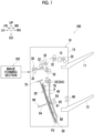
- FIG. 1 is a schematic diagram showing the configuration of the image forming apparatus 100 according to the present exemplary embodiment.
- An arrow UP shown in the drawing indicates an upper side of the apparatus, and an arrow DO indicates a lower side of the apparatus. Further, an arrow LH shown in the drawing indicates a left side of the apparatus and an arrow RH indicates a right side of the apparatus. Furthermore, an arrow FR shown in the drawing indicates a front side of the apparatus and an arrow RR indicates a rear side of the apparatus. Since these directions are directions determined for the sake of convenience of description, the configuration of the apparatus is not limited by these directions. It should be noted that regarding each of the directions relating to the apparatus, the term "apparatus" may be omitted. That is, for example, "the upper side of the apparatus” may simply be described as "the upper side.”
- up-down direction may be used to mean “both of an upward direction and a downward direction” or “any one of the upward direction or the downward direction”.
- a term “right-left direction” may be used to mean “both of a rightward direction and a leftward direction” or “any one of the rightward direction or the leftward direction”. It should be noted that the "right-left direction” may also be referred to as a lateral direction, a transverse direction, and a horizontal direction.
- front-rear direction may be used to mean “both of a forward direction and a rearward direction” or “any one of the forward direction or the rearward direction”.
- front-rear direction may also be referred to as a lateral direction, a transverse direction, and a horizontal direction.
- up-down direction, the right-left direction, and the front-rear direction are directions that intersect each other (specifically, directions orthogonal to each other).
- a symbol in which " ⁇ ” is in “o” in the drawings means an arrow from the front to the back of the sheet surface.
- a symbol in which "•” is in “ ⁇ ” in the drawings means an arrow from the back to the front of the sheet surface.
- dimensional ratios of parts shown in the respective drawings in the up-down direction, the right-left direction, and the front-rear direction may differ from actual dimensional ratios.
- the image forming apparatus 100 shown in Fig. 1 is an apparatus that forms an image on a recording medium P, and includes an image forming section 102 and a post-processing device 10 as shown in Fig. 1 .
- each section of the image forming apparatus 100 (specifically, the image forming section 102 and the post-processing device 10) will be described.
- the image forming section 102 shown in Fig. 1 is a constituent section that forms an image on the recording medium P.
- an electrophotographic image forming section that forms an image on the recording medium P using toner is used as the image forming section 102.
- each step of charging, exposure, development, transfer, and fixing is performed to form an image on the recording medium P.
- each step of charging, exposure, development, and transfer can be performed to form an image on a transfer body, the image can be transferred from the transfer body to the recording medium P, and then the image can be fixed on the recording medium P to form an image on the recording medium P.
- An example of the image forming section is not limited to the electrophotographic image forming section described above and may be, for example, an inkjet image forming section, and various image forming sections can be used.
- an ink droplet is ejected from a discharge section to the recording medium P to form an image on the recording medium P.
- the post-processing device 10 shown in Fig. 1 is a device that executes post-processing on the recording medium P on which the image forming section 102 forms an image.
- the post-processing device 10 includes a post-processing device body 13, a first ejection section 11, a second ejection section 12, a post-processing section 15, a loading section 20, a transporting mechanism 30, a guiding section 40, a supporting section 50, a pushing section 70, a moving mechanism 60 (refer to Figs. 6 and 7 ), an abutting section 75, an aligning section 80, and a post-processing section 90.
- the post-processing device 10 specifically, the post-processing device body 13, the first ejection section 11, the second ejection section 12, the post-processing section 15, the loading section 20, the transporting mechanism 30, the guiding section 40, the supporting section 50, the pushing section 70, the moving mechanism 60, the abutting section 75, the aligning section 80, and the post-processing section 90.
- the post-processing device body 13 shown in Fig. 1 is a part in which the constituent sections of the post-processing device 10 are provided.
- the post-processing device body 13 is configured to include a housing formed in a box-like shape (for example, a substantially rectangular parallelepiped shape).
- the post-processing section 15 the loading section 20, the transporting mechanism 30, the guiding section 40, the supporting section 50, the pushing section 70, and the moving mechanism 60 (refer to Figs. 6 and 7 ), the abutting section 75, the aligning section 80, and the post-processing section 90 are provided inside the post-processing device body 13.
- the first ejection section 11 and the second ejection section 12 are provided on the right side surface of the post-processing device body 13.
- the first ejection section 11 is disposed at an upper portion on a right side surface of the post-processing device body 13.
- the recording medium P, of which the post-processing has been executed by the post-processing section 15, is ejected to the first ejection section 11.
- the post-processing is processing executed on the recording medium P on which the image is formed.
- the post-processing executed by the post-processing section 15 there is binding processing of binding a plurality of recording media P with a stapler. It should be noted that the post-processing is not limited to the binding processing.
- the post-processing may be, for example, cutting processing of cutting the recording medium P, drilling processing of making a hole in the recording medium P, or the like, and may be processing executed on the recording medium P on which an image is formed.
- the second ejection section 12 is a lower portion on the right side surface of the post-processing device body 13 and is disposed under the first ejection section 11.
- the recording medium P that has been post-processed by the post-processing section 90 to be described later is ejected to the second ejection section 12.
- the loading section 20 shown in Figs. 1 and 2 is a constituent section on which the recording medium P is loaded.
- the loading section 20 is configured to have a plate body which extends obliquely upward (toward the obliquely upper left side, in the present exemplary embodiment) in a normal cross-sectional view.
- the loading section 20 has a loading surface 22 that is directed obliquely upward (toward the obliquely upper right side, in the present exemplary embodiment).
- the recording medium P is loaded on the loading surface 22 in a state where one end (hereinafter, referred to as a lower end P2) of the recording medium P faces downward (refer to Fig. 4 ).
- the loading section 20 is formed with a passage hole 24 through which the push-in portion 94 to be described later passes.
- the transporting mechanism 30 shown in Fig. 1 is a mechanism that transports the recording medium P to the loading section 20.
- the transporting mechanism 30 selectively transports the recording medium P to one of the first ejection section 11 and the loading section 20.
- the transporting mechanism 30 is configured to include a plurality of transporting rollers 32.
- the transporting rollers 32A are provided at a position facing toward the upper portion of the loading surface 22, and transport the recording medium P downward toward the loading surface 22.
- the transporting rollers 32A are an example of the transporting section.
- the guiding section 40 shown in Figs. 1 and 2 is a constituent section that guides the recording medium P transported by the transporting rollers 32A.
- the guiding section 40 is configured by using a plate body which extends obliquely upward (toward the obliquely upper left side, in the present exemplary embodiment) in a normal cross-sectional view.
- the guiding section 40 has a guiding surface 42 that is directed obliquely downward (toward the obliquely lower left side, in the present exemplary embodiment) and faces toward the loading surface 22.
- the guiding surface 42 guides the recording medium P to the loading surface 22.
- the guiding section 40 is formed with a passage hole 44 through which the push-in portion 94 to be described later passes.
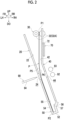
- the supporting section 50 shown in Figs. 1 and 2 is a constituent section that supports the lower end P2 of the recording medium P loaded on the loading surface 22. As shown in Figs. 1 and 2 , the supporting section 50 is disposed on the obliquely lower right side with respect to the loading section 20. As shown in Fig. 2 , the supporting section 50 has an abutting part 52, a loading part 54, and a guiding part 56.
- the abutting part 52 abuts against the lower end P2 of the recording medium P loaded on the loading surface 22 and supports the lower end P2. In a plurality of recording media P loaded on the loading surface 22, the lower end P2 is aligned by abutting the lower end P2 against the abutting part 52.
- the loading part 54 is loaded with a lower portion of the recording medium P to which the lower end P2 is abutted against the abutting part 52.
- the loading part 54 has a loading surface 55 that is directed obliquely upward (toward the obliquely upper right side, in the present exemplary embodiment).
- the loading surface 55 is disposed on the obliquely lower right side with respect to the loading surface 22 of the loading section 20 and is disposed along the loading surface 22.
- the guiding part 56 guides the lower end P2 of the recording medium P guided by the guiding section 40 to the abutting part 52 side.
- the guiding part 56 has a guiding surface 57 facing toward the loading surface 55. In the guiding part 56, the guiding surface 57 guides the recording medium P to the abutting part 52.
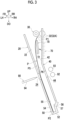
- the pushing section 70 shown in Figs. 1 and 2 is a constituent section that pushes the recording medium P, which is transported by the transporting rollers 32A, toward the loading surface 22 and moves the recording medium P to the loading surface 22 (refer to Fig. 3 ). Further, the pushing section 70 is a constituent section that comes into contact with the recording medium P loaded on the loading surface 22 to restrict bending of the recording medium P (refer to Fig. 4 ). The pushing section 70 is an example of a restricting section.
- the pushing section 70 is configured by using a plate body which extends in the up-down direction and of which the thickness direction is set as the right-left direction (refer to the solid line in Fig. 7 ).
- the pushing section 70 has a facing surface 72 which faces toward the loading surface 22 of the loading section 20.
- the facing surface 72 constitutes a flat surface which comes into contact with the recording medium P.
- a notch 73 into which the abutting section 75 is able to enter is formed at the upper end of the pushing section 70.
- the pushing section 70 has a body portion 71 that comes into contact with the recording medium P loaded on the loading surface 22 downward from the upper end P1 and a pair of protruding portions 74 that protrude upward from each of the front side part and the rear side part of the body portion 71.
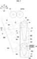
- Figs. 6 and 7 are detailed views each showing an example of a specific configuration of the pushing section 70 and the moving mechanism 60.
- the moving mechanism 60 shown in Figs. 6 and 7 is a mechanism which moves the pushing section 70 between a restriction position (a position indicated by the solid line in Fig. 4 and a position indicated by the two-dot chain line in Fig. 7 ) and a non-contact position (a position shown in Fig. 2 and a position indicated by the solid line in Fig. 7 )).
- the moving mechanism 60 has a first shaft portion 61, a pair of first links 63, a pair of side plates 65, and a second shaft portion 62, a pair of second links 64, and a driving source 69 (refer to Fig. 7 ).
- Each of the pair of side plates 65 is attached to a side of the pushing section 70 opposite to the loading surface 22 (on the right side in the present exemplary embodiment) on each of the front side and the rear side of the pushing section 70. As shown in Fig. 7 , a notch 65A, into which the second shaft portion 62 enters, and a long hole 65B, through which a connecting shaft 63A is movable, are formed on the pair of side plates 65.
- the first shaft portion 61 is rotatably supported by the post-processing device body 13 (refer to Fig. 1 ) downward with respect to the transporting rollers 32A.
- the second shaft portion 62 is rotatably supported by the post-processing device body 13 (refer to Fig. 1 ) downward with respect to the first shaft portion 61.
- each of the pair of first links 63 a base end portion 63K is fixed to the outside in the axial direction with respect to the pushing section 70 in the first shaft portion 61.
- Each apical end portions 63S of the pair of first links 63 are provided with the connecting shaft 63A connected to each of the pair of side plates 65 by being inserted into the long hole 65B so as to be movable in the long hole 65B.
- each of the pair of second links 64 a base end portion 64K is fixed to the outside in the axial direction with respect to the pushing section 70 in the second shaft portion 62.
- Each apical end portion 64S of the pair of second links 64 is provided with a connecting shaft 64A which is rotatably connected to each of the pair of side plates 65.
- the driving source 69 is configured by using, for example, a driving motor (for example, a stepping motor) that rotationally drives the second shaft portion 62.
- the driving source 69 is able to control the rotation position of the second shaft portion 62.
- the first shaft portion 61 may be rotationally driven in cell of or in addition to the rotation driving of the second shaft portion 62.
- the driving source 69 rotates the second shaft portion 62 between a first rotation position (refer to the solid line in Fig. 7 ) and a second rotation position (refer to the two-dot chain line in Fig. 7 ).
- the apical end portions 63S of the pair of first links 63 are positioned under the base end portions 63K
- the apical end portions 64S of the pair of second links 64 are positioned under the base end portions 64K.
- the second shaft portion 62 is positioned in the notch 65A, and the connecting shaft 63A of the pair of first links 63 is positioned at the lower end of the long hole 65B. Then, in the moving mechanism 60, the pushing section 70 is positioned at the non-contact position, at the first rotation position of the second shaft portion 62.
- the apical end portions 63S of the pair of first links 63 are positioned on the obliquely lower left side with respect to the base end portion 63K, and the apical end portions 64S of the pair of second links 64 are positioned on the obliquely lower left side with respect to the base end portion 64K.
- the apical end portions 63 S and 64S at the second rotation position are positioned on the left side and the upper side with respect to the apical end portions 63 S and 64S at the first rotation position.
- the second shaft portion 62 is positioned outside the notch 65A, and the connecting shaft 63A of the pair of first links 63 is positioned at the upper end of the long hole 65B. Then, in the moving mechanism 60, the pushing section 70 is positioned at the restriction position, at the second rotation position of the second shaft portion 62.
- the pushing section 70 can be moved by the moving mechanism 60 between the restriction position (the position indicated by the solid line in Fig. 4 and the position indicated by the two-dot chain line in Fig. 7 ) and the non-contact position (the position shown in Fig. 2 and the position indicated by the solid line in Fig. 7 ).
- the pushing section 70 (refer to Fig. 2 ) is not in contact with the recording medium P transported toward the loading surface 22 at the non-contact position.
- the non-contact position is also a position at which the pushing section 70 is separated from the transport path of the recording medium P transported to the loading surface 22.
- the pushing section 70 is positioned on the side of the guiding section 40 opposite to the loading section 20 (on the right side in the present exemplary embodiment) at the non-contact position.
- the pushing section 70 pushes a non-facing surface P6 of the recording medium P toward the loading surface 22 to move the recording medium P to the loading surface 22.
- the pushing section 70 pushes the non-facing surface P6 of the recording medium P toward the loading surface 22 to move the recording medium P to the loading surface 22.
- a part of the recording medium P transported by the transporting rollers 32A on the lower end P2 side is in contact with the loading surface 22, and a part of the recording medium P on the upper end P1 side is separated from the loading surface 22 and is in contact with the transporting rollers 32A (refer to Fig. 3 ).
- a part of the recording medium P on the upper end P1 side is sandwiched between the transporting rollers 32A.
- the non-facing surface P6 of the recording medium P is a surface of the recording medium P that is opposite to a facing surface P5 facing toward the loading surface 22.
- the pushing section 70 is positioned at a non-contact position at which the pushing section 70 is not in contact with the recording medium P until the transporting rollers 32A transport the recording medium P obliquely downward toward the loading surface 22 and attain the contact state, and moves from the non-contact position and pushes the non-facing surface P6 of the recording medium P toward the loading surface 22, after the recording medium P is in the contact state.
- the pushing section 70 is displaced upward from the non-contact position, moves, in a state where the facing surface 72 is along the loading surface 22, in a direction, in which the pushing section 70 approaches the loading surface 22, to push the non-facing surface P6 of the recording medium P toward the loading surface 22, and stops at a predetermined stop position (for example, the restriction position).
- a predetermined stop position for example, the restriction position.
- the stop position is separated from the loading surface 22.
- the movement operation of the pushing section 70 is realized by moving the connecting shaft 63A of the pair of first links 63 in the long hole 65B.
- the shape of the long hole 65B is set such that the pushing section 70 executes the above-mentioned movement operation.
- the pushing section 70 moves the recording medium P to the loading surface 22 and then comes into contact with the non-facing surface P6 of the recording medium P loaded on the loading surface 22 to restrict bending of the recording medium P. Specifically, the pushing section 70 comes into contact with the highest recording medium P among the plurality of recording media P loaded on the loading surface 22 to restrict bending of the recording medium P (refer to Fig. 1 ).
- the pushing section 70 moves in a state where the facing surface 72 is along the loading surface 22, in a direction in which the pushing section 70 approaches the loading surface while being displaced upward from the non-contact position 22. Then, the pushing section 70 comes into contact with the recording medium P to restrict bending of the recording medium P.
- the pushing section 70 comes into contact with the recording medium P in a state where the recording medium P loaded on the loading surface 22 is movable along the direction of pushing (toward the obliquely lower right side, in the present exemplary embodiment) performed by the abutting section 75.
- the pushing section 70 restricts bending of the recording medium P.
- a gap 72S (refer to Fig. 4 ) between the loading surface 22 and the facing surface 72 of the pushing section 70, which is in contact with the recording medium P, is greater than a thickness of all of the recording media P loaded on the loading surface 22.
- the pushing section 70 comes into contact with the recording medium P in a state of protruding upward from the upper end P1 of the recording medium P. Then, the pushing section 70 comes into contact with the recording medium P to restrict bending. Specifically, as shown in Fig. 5 , the pushing section 70 comes into contact with the recording medium P in a state where the pair of protruding portions 74 protrude upward from the upper end P1 of the recording medium P. In the state, the upper end P1 of the recording medium P is exposed between the pair of protruding portions 74, and an approach path into which the abutting section 75 is able to enter is formed between the pair of protruding portions 74.
- the pushing section 70 comes into contact with the recording medium P in a state where a part of the pushing section 70 protrudes upward from the upper end P1 of the recording medium P, thereby restricting bending of the recording medium P.
- the driving source 69 stops the second shaft portion 62 on the first rotation position side with respect to the second rotation position as the number of loaded recording media P loaded on the loading surface 22 increases. That is, the pushing section 70 increases the gap 72S as the number of loaded recording media P loaded on the loading surface 22 increases.
- the pushing section 70 pushes the non-facing surface P6 of the recording medium P toward the loading surface 22, then restricts bending of the recording medium P at the restriction position of the recording medium P, and thereafter returns to the non-contact position. Specifically, the pushing section 70 returns to the non-contact position after each end portion of the recording medium P is aligned by the abutting section 75 and the aligning section 80.
- the abutting section 75 pushes the upper end P1 of the recording medium P downward in a state where the pushing section 70 restricts bending of the recording medium P (hereinafter, referred to as a state of restriction performed by the pushing section 70), and abuts the lower end P2 against the supporting section 50.
- the upper end P1 of the recording medium P (in other words, the position of the recording medium P in the up-down direction) is aligned.
- the abutting section 75 moves from a non-contact position (the position indicated by the two-dot chain line in Fig. 5 ) that is not in contact with the recording medium P transported toward the loading surface 22, and pushes the upper end P1 of the recording medium P downward.
- the non-contact position is a position on the outside (specifically, the upper side) of the notch 73 of the pushing section 70.
- the non-contact position is also a position at which the abutting section 75 is separated from the transport path of the recording medium P transported to the loading surface 22.
- the abutting section 75 returns to the non-contact position after the lower end P2 of the recording medium P is abutted against the supporting section 50.
- the abutting section 75 comes into contact with the upper end P1 of the recording medium P in a state of entering the notch 73 of the pushing section 70. It should be noted that the upper end P1 is an end portion of the recording medium P opposite to the lower end P2.
- the aligning section 80 shown in Figs. 1 and 5 is a constituent section that aligns the side ends of the recording medium P by coming into contact with the side ends of both sides of the recording medium P in a state of the restriction performed by the pushing section 70. As shown in Fig. 5 , the aligning section 80 has a first aligning portion 81 and a second aligning portion 82.
- the first aligning portion 81 comes into contact with a side end (hereinafter, referred to as a front end P3) of one side (front side in the present exemplary embodiment) of the recording medium P
- the second aligning portion 82 comes into contact with a side end (hereinafter, referred to as the rear end P4) of the other side (rear side in the present exemplary embodiment) of the recording medium P.
- each of the first aligning portion 81 and the second aligning portion 82 moves from non-contact positions (indicated by the two-dot chain lines in Fig. 5 ), at which the first aligning portion 81 and the second aligning portion 82 are not in contact with the recording medium P transported toward the loading surface 22, and comes into contact with each of the side ends (specifically, the front end P3 and the rear end P4) of the recording medium P.
- the non-contact position is also a position at which each of the first aligning portion 81 and the second aligning portion 82 is separated from the transport path of the recording medium P transported to the loading surface 22.
- the aligning section 80 returns to the non-contact position after aligning the side ends of the recording medium P.
- the post-processing section 90 shown in Fig. 1 is a constituent section that executes the post-processing on the recording medium P loaded on the loading surface 22.
- the post-processing section 90 executes, as the post-processing, processing of binding the plurality of recording media P and folding the plurality of recording media P.
- the post-processing section 90 includes a binding portion 91, a pair of folding rollers 92 and 93, a push-in portion 94, and transporting rollers 96.
- the binding portion 91 is a so-called stapler, and the plurality of recording media P are bound by striking a needle at central portions of the plurality of recording media P loaded on the loading surface 22 in the up-down direction.
- the pair of folding rollers 92 and 93 are disposed side by side along the obliquely upper left side on the obliquely upper right side with respect to the passage hole 44 of the guiding section 40.
- the folding roller 92 rotates in the clockwise direction in Figs. 8 and 9
- the folding roller 93 rotates in the counterclockwise direction in Figs. 8 and 9 .
- the push-in portion 94 is formed in a tapered shape of which a length is longer than the length of the recording medium P loaded on the loading surface 22 in the front-rear direction and of which the apical end portion is tapered.
- the push-in portion 94 moves toward the obliquely upper right side in a direction orthogonal to the loading surface 22, pushes the apical end portion thereof into a central portion, which is a fold part in the plurality of recording media P loaded on the loading surface 22, in the up-down direction, and pushes the central portion into a gap between the pair of folding rollers 92 and 93, thereby sandwiching the plurality of recording media P between the pair of folding rollers 92 and 93 and folding the plurality of recording media P.
- the folded recording medium P is transported to the transporting rollers 96. Further, the transporting rollers 96 transport the plurality of recording media P folded by the pair of folding rollers 92 and 93 and the push-in portion 94, and ejects the recording medium P to the second ejection section 12.
- the post-processing executed by the post-processing section 90 is not limited to the above-mentioned processing.
- the post-processing for example, only one of binding processing of binding the plurality of recording media P and folding processing of folding the plurality of recording media P may be performed.
- the post-processing may be cutting processing of cutting the recording medium P, drilling processing of making a hole in the recording medium P, or the like, and may be processing executed on the recording medium P on which an image is formed.
- the pushing section 70 pushes the non-facing surface P6 of the recording medium P toward the loading surface 22 to move the recording medium P to the loading surface 22.
- the pushing section 70 may push the upper end P1 of the recording medium P, which is transported by the transporting rollers 32A, toward the loading surface 22 and may move the recording medium P to the loading surface 22 (hereinafter, referred to as a form A).
- the upper end P1 of the recording medium P may be damaged.
- a flexible member for example, a rubber member
- the degree of freedom in material selection is reduced, and the durability of the pushing section 70 is reduced.
- the non-facing surface P6 of the recording medium P is pushed toward the loading surface 22, and the recording medium P is moved to the loading surface 22. Therefore, damage to the recording medium P is suppressed, as compared with the form A. Further, according to the present exemplary embodiment, it is less necessary to consider damage to the upper end P1 of the recording medium P. Therefore, as compared with the form A, the degree of freedom in material selection of the pushing section 70 is high, and a material having a high durability can be selected as the material of the pushing section 70.
- the pushing section 70 is positioned at a non-contact position at which the pushing section 70 is not in contact with the recording medium P until the transporting rollers 32A transport the recording medium P obliquely downward toward the loading surface 22 and attain the contact state, and moves from the non-contact position and pushes the non-facing surface P6 of the recording medium P toward the loading surface 22, after the recording medium P is in the contact state.
- the pushing section 70 pushes the non-facing surface P6 of the recording medium P toward the loading surface 22, then restricts bending of the recording medium P at the restriction position of the recording medium P, and thereafter returns to the non-contact position.
- the pushing section 70 moves in a direction in which the pushing section 70 approaches the loading surface 22 while being displaced upward from the non-contact position. Thereby, the pushing section 70 pushes the non-facing surface P6 of the recording medium P toward the loading surface 22.
- the upper end P1 of the recording medium P that has moved to the loading surface 22 is suppressed from being bent rightward.
- the pushing section 70 moves in a direction in which the pushing section 70 approaches the loading surface 22 while being displaced upward from the non-contact position. Thereby, the pushing section 70 pushes the non-facing surface P6 of the recording medium P toward the loading surface 22, and stops at a predetermined stop position. Furthermore, in the present exemplary embodiment, as the number of loaded recording media P loaded on the loading surface 22 increases, the stop position is separated from the loading surface 22.
- the abutting section 75 pushes the upper end P1 of the recording medium P downward and abuts the lower end P2 against the supporting section 50 in a state of the restriction performed by the pushing section 70.
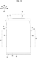
- the recording medium P loaded on the loading surface 22 is in a freely bendable state (hereinafter, referred to as a form B), as shown in Fig. 10 , the recording medium P is bent such that the upper end P1 of the recording medium P may be directed rightward. In such a case, the position of the upper end P1 is lowered. Thus, the abutting section 75 may not be able to push the upper end P1 of the recording medium P downward, and may not be able to abut the lower end P2 of the recording medium P against the supporting section 50.
- the abutting section 75 pushes the upper end P1 of the recording medium P downward and abuts the lower end P2 against the supporting section 50 in the state of the restriction performed by the pushing section 70. Therefore, as compared with the form B, trouble in abutting of the lower end P2 of the recording medium P against the supporting section 50 is suppressed.
- the pushing section 70 comes into contact with the recording medium P in a state where the recording medium P loaded on the loading surface 22 is movable along the direction of pushing (toward the obliquely lower right side, in the present exemplary embodiment) performed by the abutting section 75. As a result, the pushing section 70 restricts bending of the recording medium P.
- the gap 72S (refer to Fig. 4 ) between the loading surface 22 and the facing surface 72 of the pushing section 70, which is in contact with the recording medium P, is greater than a thickness of all of the recording media P loaded on the loading surface 22.
- the recording medium P is easily moved in the direction of pushing performed by the abutting section 75 (toward the obliquely lower right side, in the present exemplary embodiment).
- the abutting section 75 pushes the upper end P1 of the recording medium P downward, buckling of the recording medium P on the upper end P1 side is suppressed.
- the pushing section 70 increases the gap 72S as the number of loaded recording media P loaded on the loading surface 22 increases.
- the recording medium P is easily moved in the direction of pushing performed by the abutting section 75 (toward the obliquely lower right side, in the present exemplary embodiment).
- the abutting section 75 pushes the upper end P1 of the recording medium P downward, buckling of the recording medium P on the upper end P1 side is suppressed.
- the transporting rollers 32A are used as an example of the transporting section.
- the present invention is not limited thereto.
- a transport belt, a transport drum, or the like may be used, and any constituent section that is able to transport the recording medium P may be used.
- the present invention in the contact state, a part of the recording medium P transported by the transporting rollers 32A on the lower end P2 side is in contact with the loading surface 22, and a part of the recording medium P on the upper end P1 side is separated from the loading surface 22 and is sandwiched between the transporting rollers 32A.
- the present invention is not limited thereto.
- the upper end P1 of the recording medium P may come out of the transporting rollers 32A, and a part of the recording medium P on the upper end P1 side may come into contact with the transporting rollers 32A.
- the pushing section 70 has a pushing function of pushing the recording medium P, which is transported by the transporting rollers 32A, toward the loading surface 22 to move the recording medium P to the loading surface 22, and has a restricting function of coming into contact with the recording medium P loaded on the loading surface 22 to restrict bending of the recording medium P.
- the pushing section 70 may have a configuration in which only the pushing function is provided and a constituent section other than the pushing section 70 has the restricting function.
- the gap 72S (refer to Fig. 4 ) is greater than the thickness of all of the recording media P loaded on the loading surface 22.
- the present invention is not limited thereto.
- the gap 72S may be configured to have the same thickness as all of the recording media P loaded on the loading surface 22.
- the gap 72S is increased in the pushing section 70 as the number of loaded recording media P loaded on the loading surface 22 increases.
- the present invention is not limited thereto.
- the gap 72S may be configured to be consistently constant.
- the pushing section 70 is positioned at a non-contact position at which the pushing section 70 is not in contact with the recording medium P until the transporting rollers 32A transport the recording medium P obliquely downward toward the loading surface 22 and attain the contact state, and moves from the non-contact position and pushes the non-facing surface P6 of the recording medium P toward the loading surface 22, after the recording medium P is in the contact state.
- the pushing section 70 may be configured to be consistently positioned at a contact position at which the transporting rollers 32A come into contact with the recording medium P transported.
- the pushing section 70 pushes the non-facing surface P6 of the recording medium P toward the loading surface 22, then restricts bending of the recording medium P at the restriction position of the recording medium P, and thereafter returns to the non-contact position.
- the present invention is not limited thereto.
- the pushing section 70 may be configured to return to the non-contact position after pushing the non-facing surface P6 of the recording medium P toward the loading surface 22.
- the pushing section 70 moves from the non-contact position at which the pushing section 70 is not in contact with the recording medium P transported toward the loading surface 22, and comes into contact with the recording medium P to restrict bending of the recording medium P.
- the present invention is not limited thereto.
- the pushing section 70 may be configured to be consistently positioned at a contact position at which the pushing section 70 comes into contact with the recording medium P transported toward the loading surface 22.
- the pushing section 70 moves in a direction in which the pushing section 70 approaches the loading surface 22 while being displaced upward from the non-contact position and comes into contact with the recording medium P to restrict bending of the recording medium P.
- the pushing section 70 may be configured to move in a direction in which the pushing section 70 approaches the loading surface 22 while the position in the up-down direction remains constant from the non-contact position.
- the pushing section 70 moves, in a state where the facing surface 72 is along the loading surface 22, in a direction in which the pushing section 70 approaches the loading surface 22 while being displaced upward from the non-contact position.
- the present invention is not limited thereto.
- the pushing section 70 moves, in a state where the facing surface 72 facing toward the loading surface 22 is tilted with respect to the loading surface 22, in a direction in which the pushing section 70 approaches the loading surface 22 while being displaced upward from the non-contact position.
- the pushing section 70 comes into contact with the recording medium P in a state of protruding upward from the upper end P1 of the recording medium P, thereby restricting bending of the recording medium P.
- the present invention is not limited thereto.
- the pushing section 70 may be configured to come into contact with the recording medium P in a state of being positioned under the upper end P1 of the recording medium P.
- a notch 73 into which the abutting section 75 is able to enter is formed at the upper end of the pushing section 70.
- the present invention is not limited thereto.
- the upper end P1 of the pushing section 70 may be configured to be flat.
- the aligning section 80 comes into contact with the side ends on both sides of the recording medium P in a state of the restriction performed by the pushing section 70, thereby aligning the side ends of the recording medium P.
- the present invention is not limited thereto.
- the aligning section 80 may be configured to come into contact with the side ends on both sides of the recording medium P in a state where the recording medium P loaded on the loading surface 22 is in a freely bendable state.
Landscapes
- Engineering & Computer Science (AREA)
- Mechanical Engineering (AREA)
- Physics & Mathematics (AREA)
- General Physics & Mathematics (AREA)
- Pile Receivers (AREA)
- Folding Of Thin Sheet-Like Materials, Special Discharging Devices, And Others (AREA)
- Multimedia (AREA)
- Signal Processing (AREA)
Applications Claiming Priority (5)
| Application Number | Priority Date | Filing Date | Title |
|---|---|---|---|
| JP2023036732 | 2023-03-09 | ||
| JP2023050217A JP2024139329A (ja) | 2023-03-27 | 2023-03-27 | 後処理装置、及び画像形成装置 |
| JP2023148272A JP2025041156A (ja) | 2023-09-13 | 2023-09-13 | 後処理装置および画像形成システム |
| JP2023160231A JP2025051223A (ja) | 2023-09-25 | 2023-09-25 | 後処理装置、及び画像形成装置 |
| JP2023163181A JP2024139661A (ja) | 2023-03-27 | 2023-09-26 | 後処理装置、及び画像形成装置 |
Publications (2)
| Publication Number | Publication Date |
|---|---|
| EP4428077A2 true EP4428077A2 (de) | 2024-09-11 |
| EP4428077A3 EP4428077A3 (de) | 2024-12-25 |
Family
ID=89833902
Family Applications (2)
| Application Number | Title | Priority Date | Filing Date |
|---|---|---|---|
| EP24155232.2A Pending EP4428076A3 (de) | 2023-03-09 | 2024-02-01 | Nachbearbeitungsvorrichtung und entsprechende bilderzeugungsvorrichtung |
| EP24155305.6A Pending EP4428077A3 (de) | 2023-03-09 | 2024-02-01 | Nachbearbeitungsvorrichtung und entsprechende bilderzeugungsvorrichtung |
Family Applications Before (1)
| Application Number | Title | Priority Date | Filing Date |
|---|---|---|---|
| EP24155232.2A Pending EP4428076A3 (de) | 2023-03-09 | 2024-02-01 | Nachbearbeitungsvorrichtung und entsprechende bilderzeugungsvorrichtung |
Country Status (2)
| Country | Link |
|---|---|
| US (4) | US20240300767A1 (de) |
| EP (2) | EP4428076A3 (de) |
Citations (1)
| Publication number | Priority date | Publication date | Assignee | Title |
|---|---|---|---|---|
| JPH11322163A (ja) | 1998-05-13 | 1999-11-24 | Canon Aptex Inc | シート処理装置及び画像形成装置 |
Family Cites Families (21)
| Publication number | Priority date | Publication date | Assignee | Title |
|---|---|---|---|---|
| US4946153A (en) * | 1987-07-10 | 1990-08-07 | Minolta Camera Kabushiki Kaisha | Paper handling apparatus with a paper stapling function |
| JP3832964B2 (ja) * | 1998-04-06 | 2006-10-11 | 株式会社リコー | 用紙後処理装置および画像形成装置 |
| JP4379561B2 (ja) * | 2001-01-30 | 2009-12-09 | キヤノンファインテック株式会社 | シート処理装置及びこれを備えた画像形成装置 |
| JP3678721B2 (ja) * | 2002-09-11 | 2005-08-03 | 京セラミタ株式会社 | 用紙整合機構およびそれを備える後処理装置 |
| JP4211442B2 (ja) | 2003-03-17 | 2009-01-21 | 富士ゼロックス株式会社 | シート処理装置 |
| JP4123997B2 (ja) | 2003-03-24 | 2008-07-23 | 富士ゼロックス株式会社 | シート処理装置、およびシート束整合方法 |
| JP4699847B2 (ja) * | 2005-09-26 | 2011-06-15 | 京セラミタ株式会社 | 後処理装置 |
| US7673863B2 (en) * | 2006-12-22 | 2010-03-09 | Toshiba Tec Kabushiki Kaisha | Sheet post-processing apparatus |
| JP4660506B2 (ja) * | 2007-05-30 | 2011-03-30 | ニスカ株式会社 | シート後処理装置及びこれを備えた画像形成システム |
| US7975999B2 (en) * | 2007-01-31 | 2011-07-12 | Nisca Corporation | Sheet post-processing apparatus and image forming system comprising the same |
| JP5063309B2 (ja) * | 2007-11-19 | 2012-10-31 | キヤノン株式会社 | シート積載装置、シート処理装置、画像形成装置 |
| JP5511446B2 (ja) * | 2010-03-11 | 2014-06-04 | キヤノン株式会社 | シート処理装置及び画像形成装置 |
| JP5569246B2 (ja) * | 2010-08-17 | 2014-08-13 | 株式会社リコー | 用紙折り装置、用紙処理装置及び画像形成装置 |
| JP5930829B2 (ja) * | 2011-05-12 | 2016-06-08 | キヤノン株式会社 | シート処理装置 |
| JP5488559B2 (ja) * | 2011-10-06 | 2014-05-14 | コニカミノルタ株式会社 | シート後処理装置およびシート折り方法 |
| JP6086307B2 (ja) * | 2013-01-18 | 2017-03-01 | 株式会社リコー | シート処理装置及び画像形成システム |
| JP5817809B2 (ja) * | 2013-01-18 | 2015-11-18 | 株式会社リコー | シート処理装置及び画像形成システム |
| JP2015030596A (ja) | 2013-08-05 | 2015-02-16 | 株式会社リコー | 用紙後処理装置 |
| JP5939219B2 (ja) * | 2013-09-02 | 2016-06-22 | コニカミノルタ株式会社 | シート折り装置及び画像形成システム |
| US9823611B2 (en) * | 2015-04-23 | 2017-11-21 | Canon Finetech Nisca Inc. | Sheet processing device and image forming device provided with the same |
| US11492227B1 (en) * | 2021-07-09 | 2022-11-08 | Toshiba Tec Kabushiki Kaisha | Sheet post-processing apparatus |
-
2024
- 2024-02-01 EP EP24155232.2A patent/EP4428076A3/de active Pending
- 2024-02-01 US US18/429,468 patent/US20240300767A1/en active Pending
- 2024-02-01 US US18/430,622 patent/US20240300774A1/en active Pending
- 2024-02-01 EP EP24155305.6A patent/EP4428077A3/de active Pending
- 2024-02-01 US US18/429,458 patent/US20240302782A1/en active Pending
- 2024-02-01 US US18/430,558 patent/US20240302780A1/en active Pending
Patent Citations (1)
| Publication number | Priority date | Publication date | Assignee | Title |
|---|---|---|---|---|
| JPH11322163A (ja) | 1998-05-13 | 1999-11-24 | Canon Aptex Inc | シート処理装置及び画像形成装置 |
Also Published As
| Publication number | Publication date |
|---|---|
| EP4428076A3 (de) | 2024-12-18 |
| EP4428077A3 (de) | 2024-12-25 |
| US20240300774A1 (en) | 2024-09-12 |
| US20240302780A1 (en) | 2024-09-12 |
| US20240302782A1 (en) | 2024-09-12 |
| EP4428076A2 (de) | 2024-09-11 |
| US20240300767A1 (en) | 2024-09-12 |
Similar Documents
| Publication | Publication Date | Title |
|---|---|---|
| US7052005B2 (en) | Sheet postprocessing apparatus for use with image forming apparatus and folding method | |
| US7794381B2 (en) | Z-folding apparatus and sheet processing apparatus | |
| JP6115061B2 (ja) | 用紙処理装置及び画像形成システム | |
| JP5418077B2 (ja) | 画像形成システム | |
| US20090189327A1 (en) | Sheet processing apparatus | |
| EP4428077A2 (de) | Nachbearbeitungsvorrichtung und entsprechende bilderzeugungsvorrichtung | |
| EP4428078A1 (de) | Nachbearbeitungsvorrichtung und entsprechende bilderzeugungsvorrichtung | |
| JP7433899B2 (ja) | シート処理装置及び画像形成システム | |
| JP2009286522A (ja) | シート折り装置、用紙処理装置、及び画像形成装置 | |
| JP4071708B2 (ja) | 用紙処理装置及び画像形成システム | |
| JP7613016B2 (ja) | 後処理装置、及び、画像形成システム | |
| CN111302133A (zh) | 骑马订处理装置、骑马订处理装置的控制方法 | |
| JP2023107564A (ja) | 後処理装置 | |
| JP2024139329A (ja) | 後処理装置、及び画像形成装置 | |
| CN118618981A (zh) | 后处理装置及图像形成装置 | |
| JP2024139661A (ja) | 後処理装置、及び画像形成装置 | |
| JP4224393B2 (ja) | 用紙処理装置、画像形成システム、コンピュータプログラム及び記録媒体 | |
| JP2017081665A (ja) | 後処理装置、及び、画像形成装置 | |
| JP2024139324A (ja) | 後処理装置、及び画像形成装置 | |
| JP6321618B2 (ja) | シート処理装置及びこれを備えた画像形成システム | |
| JP4300040B2 (ja) | 用紙処理装置及び画像形成システム | |
| JP2004292163A (ja) | 用紙処理装置、画像形成システム、用紙処理方法、コンピュータプログラム及び記録媒体 | |
| CN114803669B (zh) | 片材后处理装置 | |
| US20260028201A1 (en) | Tamping apparatus, post-processing apparatus, and image forming apparatus | |
| JP2023004461A (ja) | シート処理装置及び画像形成システム |
Legal Events
| Date | Code | Title | Description |
|---|---|---|---|
| PUAI | Public reference made under article 153(3) epc to a published international application that has entered the european phase |
Free format text: ORIGINAL CODE: 0009012 |
|
| STAA | Information on the status of an ep patent application or granted ep patent |
Free format text: STATUS: THE APPLICATION HAS BEEN PUBLISHED |
|
| AK | Designated contracting states |
Kind code of ref document: A2 Designated state(s): AL AT BE BG CH CY CZ DE DK EE ES FI FR GB GR HR HU IE IS IT LI LT LU LV MC ME MK MT NL NO PL PT RO RS SE SI SK SM TR |
|
| PUAL | Search report despatched |
Free format text: ORIGINAL CODE: 0009013 |
|
| AK | Designated contracting states |
Kind code of ref document: A3 Designated state(s): AL AT BE BG CH CY CZ DE DK EE ES FI FR GB GR HR HU IE IS IT LI LT LU LV MC ME MK MT NL NO PL PT RO RS SE SI SK SM TR |
|
| RIC1 | Information provided on ipc code assigned before grant |
Ipc: G03G 15/00 20060101ALI20241118BHEP Ipc: B65H 31/38 20060101ALI20241118BHEP Ipc: B65H 31/02 20060101ALI20241118BHEP Ipc: B65H 45/18 20060101ALI20241118BHEP Ipc: B65H 31/26 20060101AFI20241118BHEP |
|
| STAA | Information on the status of an ep patent application or granted ep patent |
Free format text: STATUS: REQUEST FOR EXAMINATION WAS MADE |
|
| 17P | Request for examination filed |
Effective date: 20250313 |