EP4427635B1 - Möbelsystem und möbelanordnung dafür - Google Patents
Möbelsystem und möbelanordnung dafür Download PDFInfo
- Publication number
- EP4427635B1 EP4427635B1 EP23198512.8A EP23198512A EP4427635B1 EP 4427635 B1 EP4427635 B1 EP 4427635B1 EP 23198512 A EP23198512 A EP 23198512A EP 4427635 B1 EP4427635 B1 EP 4427635B1
- Authority
- EP
- European Patent Office
- Prior art keywords
- panel
- fitting member
- connecting member
- auxiliary device
- furniture
- Prior art date
- Legal status (The legal status is an assumption and is not a legal conclusion. Google has not performed a legal analysis and makes no representation as to the accuracy of the status listed.)
- Active
Links
Images


Classifications
-
- A—HUMAN NECESSITIES
- A47—FURNITURE; DOMESTIC ARTICLES OR APPLIANCES; COFFEE MILLS; SPICE MILLS; SUCTION CLEANERS IN GENERAL
- A47B—TABLES; DESKS; OFFICE FURNITURE; CABINETS; DRAWERS; GENERAL DETAILS OF FURNITURE
- A47B88/00—Drawers for tables, cabinets or like furniture; Guides for drawers
- A47B88/90—Constructional details of drawers
- A47B88/944—Drawers characterised by the front panel
- A47B88/95—Drawers characterised by the front panel characterised by connection means for the front panel
- A47B2088/951—Drawers characterised by the front panel characterised by connection means for the front panel having male and female interlocking parts
-
- A—HUMAN NECESSITIES
- A47—FURNITURE; DOMESTIC ARTICLES OR APPLIANCES; COFFEE MILLS; SPICE MILLS; SUCTION CLEANERS IN GENERAL
- A47B—TABLES; DESKS; OFFICE FURNITURE; CABINETS; DRAWERS; GENERAL DETAILS OF FURNITURE
- A47B88/00—Drawers for tables, cabinets or like furniture; Guides for drawers
- A47B88/90—Constructional details of drawers
- A47B88/944—Drawers characterised by the front panel
- A47B88/95—Drawers characterised by the front panel characterised by connection means for the front panel
- A47B2088/954—Drawers characterised by the front panel characterised by connection means for the front panel fastening the front panel by a sprung bolt, latch or lock-bolt
Definitions
- the present invention is related to a furniture assembly.
- Patent number WO 2009/111807 discloses a drawer.
- a front panel of the drawer is arranged with a drawer bar comprising a longitudinal arm and two shorter arms extending downwards at right angles.
- Each of two ends of the drawer bar is provided with a first wall element.
- Two claw elements are respectively provided on the first wall elements.
- the claw element is configured to lock a locking element in a form of a planar clamping arm.
- the shorter arms can be clamped between a rear surface of the first wall element and the locking element.
- Similar furniture assemblies are known for example from DE 11 2009 000135 B4 or US 5 385 248 A .
- the present invention aims at providing a furniture assembly having at least one auxiliary device to be installed according to user's requirements.
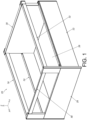
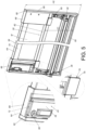
- a furniture system 20 includes a first side wall 22, a second side wall 24, a bottom plate 26, a first panel 28 and a second panel 30.
- the furniture system 20 is a drawer, but the present invention is not limited thereto.
- the first side wall 22 and the second side wall 24 are arranged at a left side and a right side of the bottom plate 26 respectively.
- the left and right sides are only for illustration to facilitate understanding of relative positions, that is, the left and right sides are interchangeable, and are not intended to limit the specific positions.
- the first panel 28 and the second panel 30 are arranged at a front side and a rear side of the bottom plate 26 respectively.
- the first panel 28 is a front panel
- the second panel 30 is a rear panel (or back panel), but the present invention is not limited thereto.
- the first side wall 22, the second side wall 24, the bottom plate 26, the first panel 28 and the second panel 30 together define an accommodating space for accommodating objects.
- the X-axis is a length direction of the furniture system 20
- the Y-axis is a width direction of the furniture system 20
- the Z-axis is a height direction of the furniture system 20.
- the length direction, the width direction and the height direction are perpendicular to each other.
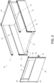
- left and right sides of the furniture system 20 have substantially identical structural arrangement.
- the left side and the right side of the furniture system 20 can be respectively arranged with a first elevated member 32 and a second elevated member 34 to increase heights of the left and right sides of the furniture system 20, so as to match heights of the first panel 28 and the second panel 30.
- the first panel 28 can be mounted to a first corresponding part 38 of the first side wall 22 through a first mounting member 36, and/or the first panel 28 can be mounted to a second corresponding part 42 of the second side wall 24 through a second mounting member 40.
- first mounting member 36 a first mounting member
- second mounting member 40 a second mounting member
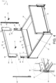
- the first elevated member 32 and the second elevated member 34 are omitted in FIG. 4 .
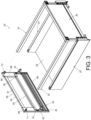
- the first panel 28 has a first side S1 and a second side S2 opposite to the first side S1.
- the furniture system 20 further comprises a first connecting member 44 arranged adjacent to the first side S1 of the first panel 28.
- the first connecting member 44 comprises a first part 46 and a second part 48.
- the first part 46 of the first connecting member 44 is configured to be connected to the first side S1 of the first panel 28.
- the first part 46 of the first connecting member 44 is connected (such as fixed) to the first side S1 of the first panel 28 through at least one fastening member 50 (as shown in FIG. 4 ).
- the furniture system 20 further comprises a second connecting member 52 arranged adjacent to the second side S2 of the first panel 28.
- the second connecting member 52 comprises a first part (not shown in FIG. 4 due to viewing angle) and a second part 56.
- the first part of the second connecting member 52 is configured to be connected to the second side S2 of the first panel 28.
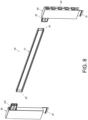
- the furniture system 20 further comprises an auxiliary device 58 configured to be mounted to the second part 48 of the first connecting member 44 and/or the second part 56 of the second connecting member 52.
- the auxiliary device 58 is configured to be mounted to the second part 48 of the first connecting member 44 and the second part 56 of the second connecting member 52.
- the first panel 28, the first connecting member 44 and the auxiliary device 58 together form a furniture assembly.
- the auxiliary device 58 is configured to increase a height of the furniture assembly above the first panel 28.
- the auxiliary device 58 is detachably mounted to the second part 48 of the first connecting member 44 and/or the second part 56 of the second connecting member 52.
- the first panel 28 comprises a bottom part 60 and a top part 62, and a first predetermined height H1 is defined between the top part 62 and the bottom part 60 of the first panel 28.
- a second predetermined height H2 is defined between a top part 64 of the auxiliary device 58 and the bottom part 60 of the first panel 28 (as shown in FIG. 5 ), and the second predetermined height H2 is higher than the first predetermined height H1.
- the second part 48 of the first connecting member 44 is extended from the first part 46.
- the second part 48 of the first connecting member 44 is substantially perpendicularly connected to the first part 46, and the second part 48 of the first connecting 44 is extended beyond the top part 62 of the first panel 28 by a predetermined distance K (as shown in FIG. 4 ).
- the second connecting member 52 has substantially identical structural configuration as the first connecting member 44, for simplification, no further illustration is provided.
- the auxiliary device 58 comprises a first fitting member 66, a second fitting member 68 and an extension member 70 arranged between the first fitting member 66 and the second fitting member 68.
- the extension member 70 is connected between the first fitting member 66 and the second fitting member 68.
- the auxiliary device 58 is configured to be mounted to the second part 48 of the first connecting member 44 through the first fitting member 66.
- the first fitting member 66 is configured to sleeve the second part 48 of the first connecting member 44 (as shown in FIG. 4 and FIG. 5 ) .
- one of the first fitting member 66 and the second part 48 of the first connecting member 44 is formed with a mounting space 72 (such as a groove), and the other one of the first fitting member 66 and the second part 48 of the first connecting member 44 is configured to be inserted into the mounting space 72 (as shown in FIG. 5 ), such that the first fitting member 66 and the second part 48 of the first connecting member 44 can be connected to each other.
- the second fitting member 68 is configured to sleeve the second part 56 of the second connecting member 52, such that the second fitting member 68 and the second part 56 of the second connecting member 52 can be connected to each other.
- the second fitting member 68 and the second part 56 of the second connecting member 52 can be connected to each other.
- the furniture system 20 further comprises a first fixing member 71 configured to fixedly connect the first fitting member 66 with the first connecting member 44 to each other.
- the furniture system 20 further comprises a second fixing member 73 configured to fixedly connect the second fitting member 68 with the second connecting member 52.
- the first fixing member 71 is configured to be mounted to a first corresponding feature 75 of the first elevated member 32
- the second fixing member 73 is configured to be mounted to a second corresponding feature 77 of the second elevated member 34 (please refer to FIG. 2 and FIG. 3 ).
- the first panel 28 comprises a predetermined portion 76. At least one of the first fitting member 66 and the second fitting member 68 is arranged with a hook configured to engage with the predetermined portion 76 of the first panel 28.
- the first fitting member 66 is arranged with a first hook 78
- the second fitting member 68 is arranged with a second hook 80.
- the first hook 78 and the second hook 80 are elastic.
- the first hook 78 and the second hook 80 are made of plastic; in other alternative embodiment, the first hook 78 and the second hook 80 are made of metal, but the present invention is not limited thereto.
- the extension member 70 is a rod, and the extension member 70, the first fitting member 66, the second fitting member 68, and the top part 62 of the first panel 28 together define a predetermined space M (as shown in FIG. 5 and FIG. 6 ).
- the furniture system 20 further comprises a first side cover 82, and the first fitting member 66 comprises a first side part 84.
- the first side cover 82 is configured to cover the first side part 84 of the first fitting member 66 and the first side S1 of the first panel 28.
- the furniture system 20 further comprises a second side cover 86, and the second fitting member 68 comprises a second side part 88.
- the second side cover 86 is configured to cover the second side part 88 of the second fitting member 68 and the second side S2 of the first panel 28.
- one of the first side cover 82 and the first side part 84 of the first fitting member 66 has at least one first connecting feature 90, such as a protrusion or an auxiliary hook, configured to connect the other one of the first side cover 82 and the first side part 84 of the first fitting member 66, such that the first side cover 82 and the first side part 84 of the first fitting member 66 are pressed against each other or buckled together.
- first connecting feature 90 such as a protrusion or an auxiliary hook
- one of the second side cover 86 and the second side part 88 of the second fitting member 68 has at least one second connecting feature 92, such as a protrusion or an auxiliary hook, configured to connect the other one of the second side cover 86 and the second side part 88 of the second fitting member 68, such that the second side cover 86 and the second side part 88 of the second fitting member 68 are pressed against each other or buckled together.
- second connecting feature 92 such as a protrusion or an auxiliary hook
- a user can put his hand into the predetermined space M, and hold the auxiliary device 58 (the extension member 70 of the auxiliary device 58) to apply a force F to open the furniture system 20 relative to a cabinet (not shown in figures) along a predetermined direction (such as an opening direction).
- a predetermined direction such as an opening direction
- the auxiliary device 58 Through engaging the first hook 78 of the first fitting member 66 (and/or the second hook 80 of the second fitting member 68) with the first panel 28 (the predetermined position 76 of the first panel 28), the auxiliary device 58 (with the second part 48 of the first connecting member 44 and/or the second part 56 of the second connecting member 52) can be prevented from being tilted or deformed relative to the first panel 28 due to unexpected movement of the auxiliary device 58 in order to improve structural strength and reliability of the auxiliary device 58.
- the extension member 70 of the auxiliary device 58 has a first side end 94 and a second side end 96 opposite to the first side end 94.
- the first fitting member 66 is configured to be detachably mounted to the first side end 94.
- the second fitting member 68 is configured to be detachably mounted to the second side end 96.
- the first side end 94 of the extension member 70 is formed with a first accommodating space configured to mount a first extension part 98 of the first fitting member 66
- the second side end 96 of the extension member 70 is formed with a second accommodating space configured to mount a second extension part 100 of the second fitting member 68.
- the auxiliary device 58 can meet diverse mounting requirements of the market.
- the extension member 70, the first fitting member 66 and the second fitting member 68 of the auxiliary device 58 can also be integrated together, but the present invention is not limited thereto.
Landscapes
- Combinations Of Kitchen Furniture (AREA)
- Furniture Connections (AREA)
- Drawers Of Furniture (AREA)
Claims (8)
- Möbelvorrichtung, aufweisend:eine erste Platte (28), welche eine erste Seite und eine zweite Seite hat;ein Verbindungselement (44, 52), welches benachbart zu einer von der ersten Seite und der zweiten Seite der ersten Platte (28) angeordnet ist, wobei das Verbindungselement (44, 52) einen ersten Teil (46) und einen zweiten Teil (48, 56) aufweist, wobei der erste Teil (46) konfiguriert ist, um mit der ersten Platte (28) verbunden zu sein; undeine Hilfsvorrichtung (58), welche konfiguriert ist, um an dem zweiten Teil (48, 56) des Verbindungselements (44, 52) montiert zu sein, um eine Höhe der Möbelvorrichtung über die erste Platte (28) hinaus zu erhöhen;wobei die erste Platte (28) einen unteren Teil (60) und einen oberen Teil (62) aufweist, und eine erste vorbestimmte Höhe zwischen dem oberen Teil (62) und dem unteren Teil (60) der ersten Platte (28) definiert ist; wobei, wenn die Hilfsvorrichtung (58) an dem zweiten Teil (48, 56) des Verbindungselements (44, 52) montiert ist, eine zweite vorbestimmte Höhe zwischen einem oberen Teil (64) der Hilfsvorrichtung (58) und dem unteren Teil (60) der ersten Platte (28) definiert ist, und die zweite vorbestimmte Höhe höher als die erste vorbestimmte Höhe ist;wobei die Hilfsvorrichtung (58) ein erstes Montage-Element (66), ein zweites Montage-Element (68) und ein Fortsatzelement (70) aufweist, welches zwischen dem ersten Montage-Element (66) und dem zweiten Montage-Element (68) angeordnet ist;wobei die Hilfsvorrichtung (58) an dem zweiten Teil (48, 56) des Verbindungselements (44, 52) durch das erste Montage-Element (66) befestigt ist;dadurch gekennzeichnet, dass die erste Platte (28) einen vorbestimmten Abschnitt (76) aufweist, und eines von dem ersten Montage-Element (66) und dem zweiten Montage-Element (68) mit einem Haken (78, 80) angeordnet ist, welcher konfiguriert ist, um mit dem vorbestimmten Abschnitt (76) der ersten Platte (28) in Eingriff zu stehen.
- Möbelvorrichtung gemäß Anspruch 1, dadurch gekennzeichnet, dass der zweite Teil (48, 56) des Verbindungselements (44, 52) von dem ersten Teil (46) aus erstreckt ist, und der zweite Teil (48, 56) des Verbindungselements (44, 52) um einen vorbestimmten Abstand über den oberen Teil (62) der ersten Platte (28) hinaus erstreckt ist.
- Möbelvorrichtung gemäß Anspruch 1, dadurch gekennzeichnet, dass das erste Montage-Element (66) konfiguriert ist, um den zweiten Teil (48, 56) des Verbindungselements (44, 52) zu ummanteln.
- Möbelvorrichtung gemäß Anspruch 1, dadurch gekennzeichnet, dass der Haken (78, 80) elastisch ist.
- Möbelvorrichtung gemäß einem der Ansprüche 1 bis 4, dadurch gekennzeichnet, dass das Fortsatzelement (70) ein Erste-Seite-Ende (94) und ein Zweite-Seite-Ende (96) hat, und das erste Montage-Element (66) konfiguriert ist, um in abnehmbarer Weise an dem Erste-Seite-Ende (94) montiert zu sein.
- Möbelvorrichtung gemäß Anspruch 5, dadurch gekennzeichnet, dass das zweite Montage-Element (68) konfiguriert ist, um in abnehmbarer Weise an dem Zweite-Seite-Ende (96) montiert zu sein.
- Möbelvorrichtung gemäß einem der Ansprüche 1 bis 6, dadurch gekennzeichnet, dass das Fortsatzelement (70) eine Stange ist, und ein vorbestimmter Raum mittels des Fortsatzelements (70), des ersten Montage-Elements (66), des zweiten Montage-Elements (68) und des oberen Teils (62) der ersten Platte (28) definiert ist.
- Möbelvorrichtung gemäß einem der Ansprüche 1 bis 4, ferner gekennzeichnet durch eine Seitenabdeckung (82), wobei das erste Montage-Element (66) einen Seitenteil (84) aufweist, und die Seitenabdeckung (82) konfiguriert ist, um den Seitenteil (84) des ersten Montage-Elements (66) und die erste Seite der ersten Platte (28) zu bedecken.
Applications Claiming Priority (1)
| Application Number | Priority Date | Filing Date | Title |
|---|---|---|---|
| TW112108391A TWI843468B (zh) | 2023-03-06 | 2023-03-06 | 傢俱及其傢俱組件 |
Publications (2)
| Publication Number | Publication Date |
|---|---|
| EP4427635A1 EP4427635A1 (de) | 2024-09-11 |
| EP4427635B1 true EP4427635B1 (de) | 2025-06-04 |
Family
ID=88097892
Family Applications (1)
| Application Number | Title | Priority Date | Filing Date |
|---|---|---|---|
| EP23198512.8A Active EP4427635B1 (de) | 2023-03-06 | 2023-09-20 | Möbelsystem und möbelanordnung dafür |
Country Status (4)
| Country | Link |
|---|---|
| US (1) | US12324516B2 (de) |
| EP (1) | EP4427635B1 (de) |
| JP (1) | JP7683853B2 (de) |
| TW (1) | TWI843468B (de) |
Family Cites Families (46)
| Publication number | Priority date | Publication date | Assignee | Title |
|---|---|---|---|---|
| DE3024972C2 (de) * | 1980-07-02 | 1984-12-13 | Bbp-Kunststoffwerk Marbach Baier & Co, 7142 Marbach | Auszug, insbesondere Topfauszug, für Möbel |
| JPS5745344U (de) * | 1980-08-29 | 1982-03-12 | ||
| AT372263B (de) * | 1980-09-24 | 1983-09-26 | Blum Gmbh Julius | Befestigungsvorrichtung fuer verstellbare frontplatten |
| JPS5858745U (ja) * | 1981-10-16 | 1983-04-20 | 株式会社 くろがね工作所 | 取手取付装置 |
| AT391253B (de) * | 1986-05-14 | 1990-09-10 | Blum Gmbh Julius | Beschlagbausatz fuer eine aus mehreren teilen zusammensetzbare schublade |
| AT399260B (de) * | 1987-05-22 | 1995-04-25 | Blum Gmbh Julius | Schublade |
| US5265953A (en) * | 1987-05-22 | 1993-11-30 | Julius Blum Gesellschaft M.B.H. | Drawer |
| DE4330919A1 (de) * | 1993-09-11 | 1995-03-16 | Lautenschlaeger Mepla Werke | Eck-Verbindungsbeschlag für Schubladen |
| DE9404708U1 (de) * | 1994-03-21 | 1994-07-21 | Paul Hettich & Co, 32278 Kirchlengern | Verstellbare Stützeinrichtung für eine Frontplatte eines Schubkastens, eines Auszuges o.dgl. |
| US5385248A (en) | 1994-06-06 | 1995-01-31 | Klein, Jr.; Frederick H. | Decorative multi-component hardware items and method of assembling the same |
| AT407332B (de) * | 1997-03-21 | 2001-02-26 | Blum Gmbh Julius | Schublade |
| EP0974291A2 (de) * | 1998-07-24 | 2000-01-26 | Miguel Angel D. Rioja Calvo | Schublade für Möbel |
| KR200188099Y1 (ko) * | 2000-02-02 | 2000-07-15 | 주식회사에넥스 | 서랍장 |
| AT6717U1 (de) * | 2003-03-19 | 2004-03-25 | Blum Gmbh Julius | Schublade |
| KR200377357Y1 (ko) * | 2004-12-15 | 2005-03-11 | 장근대 | 서랍의 전면판 결합구조 |
| AT505432B1 (de) * | 2007-07-11 | 2012-08-15 | Blum Gmbh Julius | Schubladenzarge mit einer befestigungseinrichtung für eine frontblende |
| AT506440B1 (de) * | 2008-03-10 | 2012-10-15 | Blum Gmbh Julius | Schublade mit einer befestigungseinrichtung für wandelemente |
| DE202008011505U1 (de) * | 2008-04-18 | 2009-08-27 | Paul Hettich Gmbh & Co. Kg | Schubkasten |
| DE202008008540U1 (de) * | 2008-06-30 | 2009-11-19 | Paul Hettich Gmbh & Co. Kg | Wandelement |
| DE202008009507U1 (de) * | 2008-07-15 | 2008-11-06 | Grass Gmbh | Möbel und verschiebbar an einer Möbelteilaufnahme anbringbares Möbelteil |
| DE102008057170B4 (de) * | 2008-11-13 | 2017-08-24 | Fackelmann Gmbh + Co Kg | Schublade und Adapterelement |
| DE102010037281A1 (de) * | 2010-09-02 | 2012-03-08 | Paul Hettich Gmbh & Co. Kg | Möbelauszugsteil |
| AT510906A1 (de) * | 2011-01-03 | 2012-07-15 | Blum Gmbh Julius | Reling für ein bewegbares möbelteil |
| AT511683B1 (de) * | 2011-07-07 | 2014-07-15 | Blum Gmbh Julius | Schublade |
| AT511905B1 (de) * | 2011-08-30 | 2014-08-15 | Blum Gmbh Julius | Schublade |
| AT511849B1 (de) * | 2011-10-17 | 2013-03-15 | Blum Gmbh Julius | Verbindungsvorrichtung zum verbinden zweier rechtwinklig anzuordnender schubladenwandteile |
| DE202011109565U1 (de) * | 2011-12-23 | 2013-03-25 | Grass Gmbh | Vorrichtung zur Anbindung eines Möbelauszugs an einer Möbelfront |
| DE202012100211U1 (de) * | 2012-01-20 | 2012-03-01 | fs küchen GmbH | Einbauküche oder Küchenzeile |
| DE102012101220A1 (de) * | 2012-02-15 | 2013-08-22 | Paul Hettich Gmbh & Co. Kg | Schubkasten |
| DE202012003125U1 (de) * | 2012-02-20 | 2013-06-13 | Bulthaup Gmbh & Co. Kg | Auszug |
| DE202015100770U1 (de) * | 2015-02-18 | 2016-05-19 | Grass Gmbh | Abdeckkappe oben offen Modul i |
| DE102015110561A1 (de) * | 2015-07-01 | 2017-01-05 | Form Orange Produktentwicklung | Schublade mit einer Bodenplatte, einer Blende, einer Rückwand und zwei Seitenwänden, die fest miteinander verbunden sind |
| AT518790B1 (de) * | 2017-02-21 | 2018-01-15 | Blum Gmbh Julius | Verbindungsstift für Möbelteile |
| DE102017105798A1 (de) * | 2017-03-17 | 2018-09-20 | Paul Hettich Gmbh & Co. Kg | Zarge für einen Schubkasten |
| TWI616161B (zh) * | 2017-04-12 | 2018-03-01 | 川湖科技股份有限公司 | 用於傢俱組件的離合器 |
| DE202017003832U1 (de) * | 2017-07-19 | 2018-10-22 | Grass Gmbh | Vorrichtung zur Verbindung einer Front mit einer Zarge |
| AT18053U1 (de) * | 2017-12-21 | 2023-12-15 | Blum Gmbh Julius | Relingstrebe für eine Schublade |
| AT520788B1 (de) * | 2017-12-21 | 2023-03-15 | Blum Gmbh Julius | Schubladenanordnung |
| AT520636B1 (de) * | 2018-01-26 | 2019-06-15 | Blum Gmbh Julius | Frontblende für eine Schublade |
| DE102019122855A1 (de) * | 2019-08-26 | 2021-03-04 | Paul Hettich Gmbh & Co. Kg | Seitenzarge für einen Schubkasten |
| DE202019104971U1 (de) * | 2019-09-09 | 2020-12-10 | Vauth-Sagel Holding Gmbh & Co. Kg | Schubkastenblende |
| TWI712381B (zh) * | 2020-02-25 | 2020-12-11 | 川湖科技股份有限公司 | 用於傢俱組件的安裝裝置與安裝方法 |
| JP7641611B2 (ja) * | 2020-07-30 | 2025-03-07 | 河淳株式会社 | 与薬ラック |
| CN111870072A (zh) * | 2020-08-21 | 2020-11-03 | 广东东泰五金精密制造有限公司 | 一种抽屉侧板与面板装配结构 |
| CN111904185B (zh) * | 2020-08-28 | 2025-01-07 | 广东东泰五金精密制造有限公司 | 一种优化的家具抽屉装配结构 |
| CN112056827B (zh) * | 2020-09-11 | 2025-04-15 | 广东东泰五金精密制造有限公司 | 一种家具抽屉的简便装配结构 |
-
2023
- 2023-03-06 TW TW112108391A patent/TWI843468B/zh active
- 2023-07-05 US US18/347,002 patent/US12324516B2/en active Active
- 2023-09-20 EP EP23198512.8A patent/EP4427635B1/de active Active
- 2023-10-13 JP JP2023177175A patent/JP7683853B2/ja active Active
Also Published As
| Publication number | Publication date |
|---|---|
| TWI843468B (zh) | 2024-05-21 |
| JP7683853B2 (ja) | 2025-05-27 |
| EP4427635A1 (de) | 2024-09-11 |
| US20240298794A1 (en) | 2024-09-12 |
| US12324516B2 (en) | 2025-06-10 |
| TW202435796A (zh) | 2024-09-16 |
| JP2024125986A (ja) | 2024-09-19 |
Similar Documents
| Publication | Publication Date | Title |
|---|---|---|
| EP3449766B1 (de) | Auszugsführung | |
| EP3708031B1 (de) | Anschlussvorrichtung | |
| EP3322269A1 (de) | Klammervorrichtung und gleitschienenanordnung damit | |
| EP3131375B1 (de) | Gleitschienenanordnung und haltevorrichtung dafür | |
| EP2428690B1 (de) | Klemme | |
| EP3847925B1 (de) | Verbindungsvorrichtung | |
| EP4302651B1 (de) | Möbel und möbelteilanordnung dafür | |
| EP3525562B1 (de) | Anschlussvorrichtung für kabelmanagementvorrichtung und gleitschienenanordnung | |
| JP6817396B2 (ja) | 引き出し及びその家具フィッティング | |
| EP4427635B1 (de) | Möbelsystem und möbelanordnung dafür | |
| EP4302650B1 (de) | Möbel und möbelteilanordnung dafür | |
| JP2020078540A (ja) | ブラケット装置 | |
| EP4427633A1 (de) | Möbelsystem und möbelanordnung dafür | |
| EP4629760A1 (de) | Gleitschienenanordnung | |
| JP2021150427A (ja) | L型レールの取付構造 | |
| EP4427634B1 (de) | Möbelanordnung | |
| CN111713898B (zh) | 连接装置 | |
| JP3739128B2 (ja) | コネクタ保持機構 | |
| CN222615760U (zh) | 紧固件 | |
| CN118614718A (zh) | 家具及其家具组件 | |
| JP6764155B2 (ja) | ケーブルクランプ | |
| JP4358360B2 (ja) | 棚板への側板取付構造 | |
| CN117432693A (zh) | 家具及其家具组件 | |
| JP3313346B2 (ja) | 家具部品及び家具部品の取付構造 | |
| JP2024066632A (ja) | ヒンジおよび扉 |
Legal Events
| Date | Code | Title | Description |
|---|---|---|---|
| PUAI | Public reference made under article 153(3) epc to a published international application that has entered the european phase |
Free format text: ORIGINAL CODE: 0009012 |
|
| STAA | Information on the status of an ep patent application or granted ep patent |
Free format text: STATUS: REQUEST FOR EXAMINATION WAS MADE |
|
| 17P | Request for examination filed |
Effective date: 20240611 |
|
| AK | Designated contracting states |
Kind code of ref document: A1 Designated state(s): AL AT BE BG CH CY CZ DE DK EE ES FI FR GB GR HR HU IE IS IT LI LT LU LV MC ME MK MT NL NO PL PT RO RS SE SI SK SM TR |
|
| GRAP | Despatch of communication of intention to grant a patent |
Free format text: ORIGINAL CODE: EPIDOSNIGR1 |
|
| STAA | Information on the status of an ep patent application or granted ep patent |
Free format text: STATUS: GRANT OF PATENT IS INTENDED |
|
| RIC1 | Information provided on ipc code assigned before grant |
Ipc: A47B 88/944 20170101AFI20250217BHEP |
|
| INTG | Intention to grant announced |
Effective date: 20250228 |
|
| GRAS | Grant fee paid |
Free format text: ORIGINAL CODE: EPIDOSNIGR3 |
|
| GRAA | (expected) grant |
Free format text: ORIGINAL CODE: 0009210 |
|
| STAA | Information on the status of an ep patent application or granted ep patent |
Free format text: STATUS: THE PATENT HAS BEEN GRANTED |
|
| AK | Designated contracting states |
Kind code of ref document: B1 Designated state(s): AL AT BE BG CH CY CZ DE DK EE ES FI FR GB GR HR HU IE IS IT LI LT LU LV MC ME MK MT NL NO PL PT RO RS SE SI SK SM TR |
|
| REG | Reference to a national code |
Ref country code: GB Ref legal event code: FG4D |
|
| REG | Reference to a national code |
Ref country code: CH Ref legal event code: EP |
|
| REG | Reference to a national code |
Ref country code: DE Ref legal event code: R096 Ref document number: 602023003821 Country of ref document: DE |
|
| REG | Reference to a national code |
Ref country code: IE Ref legal event code: FG4D |
|
| REG | Reference to a national code |
Ref country code: NL Ref legal event code: MP Effective date: 20250604 |
|
| PG25 | Lapsed in a contracting state [announced via postgrant information from national office to epo] |
Ref country code: ES Free format text: LAPSE BECAUSE OF FAILURE TO SUBMIT A TRANSLATION OF THE DESCRIPTION OR TO PAY THE FEE WITHIN THE PRESCRIBED TIME-LIMIT Effective date: 20250604 Ref country code: FI Free format text: LAPSE BECAUSE OF FAILURE TO SUBMIT A TRANSLATION OF THE DESCRIPTION OR TO PAY THE FEE WITHIN THE PRESCRIBED TIME-LIMIT Effective date: 20250604 |
|
| PGFP | Annual fee paid to national office [announced via postgrant information from national office to epo] |
Ref country code: DE Payment date: 20250826 Year of fee payment: 3 |
|
| REG | Reference to a national code |
Ref country code: LT Ref legal event code: MG9D |
|
| PG25 | Lapsed in a contracting state [announced via postgrant information from national office to epo] |
Ref country code: NO Free format text: LAPSE BECAUSE OF FAILURE TO SUBMIT A TRANSLATION OF THE DESCRIPTION OR TO PAY THE FEE WITHIN THE PRESCRIBED TIME-LIMIT Effective date: 20250904 Ref country code: GR Free format text: LAPSE BECAUSE OF FAILURE TO SUBMIT A TRANSLATION OF THE DESCRIPTION OR TO PAY THE FEE WITHIN THE PRESCRIBED TIME-LIMIT Effective date: 20250905 |
|
| PG25 | Lapsed in a contracting state [announced via postgrant information from national office to epo] |
Ref country code: PL Free format text: LAPSE BECAUSE OF FAILURE TO SUBMIT A TRANSLATION OF THE DESCRIPTION OR TO PAY THE FEE WITHIN THE PRESCRIBED TIME-LIMIT Effective date: 20250604 |
|
| PG25 | Lapsed in a contracting state [announced via postgrant information from national office to epo] |
Ref country code: BG Free format text: LAPSE BECAUSE OF FAILURE TO SUBMIT A TRANSLATION OF THE DESCRIPTION OR TO PAY THE FEE WITHIN THE PRESCRIBED TIME-LIMIT Effective date: 20250604 |
|
| PG25 | Lapsed in a contracting state [announced via postgrant information from national office to epo] |
Ref country code: HR Free format text: LAPSE BECAUSE OF FAILURE TO SUBMIT A TRANSLATION OF THE DESCRIPTION OR TO PAY THE FEE WITHIN THE PRESCRIBED TIME-LIMIT Effective date: 20250604 |
|
| PGFP | Annual fee paid to national office [announced via postgrant information from national office to epo] |
Ref country code: AT Payment date: 20251020 Year of fee payment: 3 |
|
| PG25 | Lapsed in a contracting state [announced via postgrant information from national office to epo] |
Ref country code: RS Free format text: LAPSE BECAUSE OF FAILURE TO SUBMIT A TRANSLATION OF THE DESCRIPTION OR TO PAY THE FEE WITHIN THE PRESCRIBED TIME-LIMIT Effective date: 20250904 |
|
| PGFP | Annual fee paid to national office [announced via postgrant information from national office to epo] |
Ref country code: IE Payment date: 20250805 Year of fee payment: 3 |
|
| PG25 | Lapsed in a contracting state [announced via postgrant information from national office to epo] |
Ref country code: LV Free format text: LAPSE BECAUSE OF FAILURE TO SUBMIT A TRANSLATION OF THE DESCRIPTION OR TO PAY THE FEE WITHIN THE PRESCRIBED TIME-LIMIT Effective date: 20250604 |
|
| PG25 | Lapsed in a contracting state [announced via postgrant information from national office to epo] |
Ref country code: NL Free format text: LAPSE BECAUSE OF FAILURE TO SUBMIT A TRANSLATION OF THE DESCRIPTION OR TO PAY THE FEE WITHIN THE PRESCRIBED TIME-LIMIT Effective date: 20250604 |
|
| PG25 | Lapsed in a contracting state [announced via postgrant information from national office to epo] |
Ref country code: PT Free format text: LAPSE BECAUSE OF FAILURE TO SUBMIT A TRANSLATION OF THE DESCRIPTION OR TO PAY THE FEE WITHIN THE PRESCRIBED TIME-LIMIT Effective date: 20251006 |
|
| REG | Reference to a national code |
Ref country code: AT Ref legal event code: MK05 Ref document number: 1799485 Country of ref document: AT Kind code of ref document: T Effective date: 20250604 |
|
| PG25 | Lapsed in a contracting state [announced via postgrant information from national office to epo] |
Ref country code: IS Free format text: LAPSE BECAUSE OF FAILURE TO SUBMIT A TRANSLATION OF THE DESCRIPTION OR TO PAY THE FEE WITHIN THE PRESCRIBED TIME-LIMIT Effective date: 20251004 |
|
| PG25 | Lapsed in a contracting state [announced via postgrant information from national office to epo] |
Ref country code: SM Free format text: LAPSE BECAUSE OF FAILURE TO SUBMIT A TRANSLATION OF THE DESCRIPTION OR TO PAY THE FEE WITHIN THE PRESCRIBED TIME-LIMIT Effective date: 20250604 Ref country code: AT Free format text: LAPSE BECAUSE OF FAILURE TO SUBMIT A TRANSLATION OF THE DESCRIPTION OR TO PAY THE FEE WITHIN THE PRESCRIBED TIME-LIMIT Effective date: 20250604 |
|
| PG25 | Lapsed in a contracting state [announced via postgrant information from national office to epo] |
Ref country code: CZ Free format text: LAPSE BECAUSE OF FAILURE TO SUBMIT A TRANSLATION OF THE DESCRIPTION OR TO PAY THE FEE WITHIN THE PRESCRIBED TIME-LIMIT Effective date: 20250604 |
|
| PG25 | Lapsed in a contracting state [announced via postgrant information from national office to epo] |
Ref country code: EE Free format text: LAPSE BECAUSE OF FAILURE TO SUBMIT A TRANSLATION OF THE DESCRIPTION OR TO PAY THE FEE WITHIN THE PRESCRIBED TIME-LIMIT Effective date: 20250604 |
|
| PG25 | Lapsed in a contracting state [announced via postgrant information from national office to epo] |
Ref country code: SK Free format text: LAPSE BECAUSE OF FAILURE TO SUBMIT A TRANSLATION OF THE DESCRIPTION OR TO PAY THE FEE WITHIN THE PRESCRIBED TIME-LIMIT Effective date: 20250604 |
|
| PG25 | Lapsed in a contracting state [announced via postgrant information from national office to epo] |
Ref country code: IT Free format text: LAPSE BECAUSE OF FAILURE TO SUBMIT A TRANSLATION OF THE DESCRIPTION OR TO PAY THE FEE WITHIN THE PRESCRIBED TIME-LIMIT Effective date: 20250604 |
|
| REG | Reference to a national code |
Ref country code: DE Ref legal event code: R097 Ref document number: 602023003821 Country of ref document: DE |
|
| PG25 | Lapsed in a contracting state [announced via postgrant information from national office to epo] |
Ref country code: RO Free format text: LAPSE BECAUSE OF FAILURE TO SUBMIT A TRANSLATION OF THE DESCRIPTION OR TO PAY THE FEE WITHIN THE PRESCRIBED TIME-LIMIT Effective date: 20250604 |
|
| PLBE | No opposition filed within time limit |
Free format text: ORIGINAL CODE: 0009261 |
|
| STAA | Information on the status of an ep patent application or granted ep patent |
Free format text: STATUS: NO OPPOSITION FILED WITHIN TIME LIMIT |
|
| PG25 | Lapsed in a contracting state [announced via postgrant information from national office to epo] |
Ref country code: DK Free format text: LAPSE BECAUSE OF FAILURE TO SUBMIT A TRANSLATION OF THE DESCRIPTION OR TO PAY THE FEE WITHIN THE PRESCRIBED TIME-LIMIT Effective date: 20250604 |
|
| REG | Reference to a national code |
Ref country code: CH Ref legal event code: L10 Free format text: ST27 STATUS EVENT CODE: U-0-0-L10-L00 (AS PROVIDED BY THE NATIONAL OFFICE) Effective date: 20260416 |