EP4425909A1 - Fernseher und steuerungsverfahren dafür - Google Patents
Fernseher und steuerungsverfahren dafür Download PDFInfo
- Publication number
- EP4425909A1 EP4425909A1 EP21962569.6A EP21962569A EP4425909A1 EP 4425909 A1 EP4425909 A1 EP 4425909A1 EP 21962569 A EP21962569 A EP 21962569A EP 4425909 A1 EP4425909 A1 EP 4425909A1
- Authority
- EP
- European Patent Office
- Prior art keywords
- screen
- motor
- exposed
- memory
- user
- Prior art date
- Legal status (The legal status is an assumption and is not a legal conclusion. Google has not performed a legal analysis and makes no representation as to the accuracy of the status listed.)
- Pending
Links
Images


Classifications
-
- H—ELECTRICITY
- H04—ELECTRIC COMMUNICATION TECHNIQUE
- H04N—PICTORIAL COMMUNICATION, e.g. TELEVISION
- H04N5/00—Details of television systems
- H04N5/64—Constructional details of receivers, e.g. cabinets or dust covers
-
- G—PHYSICS
- G06—COMPUTING OR CALCULATING; COUNTING
- G06F—ELECTRIC DIGITAL DATA PROCESSING
- G06F1/00—Details not covered by groups G06F3/00 - G06F13/00 and G06F21/00
- G06F1/16—Constructional details or arrangements
- G06F1/1613—Constructional details or arrangements for portable computers
- G06F1/1633—Constructional details or arrangements of portable computers not specific to the type of enclosures covered by groups G06F1/1615 - G06F1/1626
- G06F1/1637—Details related to the display arrangement, including those related to the mounting of the display in the housing
- G06F1/1652—Details related to the display arrangement, including those related to the mounting of the display in the housing the display being flexible, e.g. mimicking a sheet of paper, or rollable
-
- H—ELECTRICITY
- H04—ELECTRIC COMMUNICATION TECHNIQUE
- H04N—PICTORIAL COMMUNICATION, e.g. TELEVISION
- H04N21/00—Selective content distribution, e.g. interactive television or video on demand [VOD]
- H04N21/40—Client devices specifically adapted for the reception of or interaction with content, e.g. set-top-box [STB]; Operations thereof
- H04N21/41—Structure of client; Structure of client peripherals
- H04N21/422—Input-only peripherals, i.e. input devices connected to specially adapted client devices, e.g. global positioning system [GPS]
- H04N21/42204—User interfaces specially adapted for controlling a client device through a remote control device; Remote control devices therefor
- H04N21/42206—User interfaces specially adapted for controlling a client device through a remote control device; Remote control devices therefor characterized by hardware details
- H04N21/4222—Remote control device emulator integrated into a non-television apparatus, e.g. a PDA, media center or smart toy
-
- H—ELECTRICITY
- H04—ELECTRIC COMMUNICATION TECHNIQUE
- H04N—PICTORIAL COMMUNICATION, e.g. TELEVISION
- H04N21/00—Selective content distribution, e.g. interactive television or video on demand [VOD]
- H04N21/40—Client devices specifically adapted for the reception of or interaction with content, e.g. set-top-box [STB]; Operations thereof
- H04N21/41—Structure of client; Structure of client peripherals
- H04N21/422—Input-only peripherals, i.e. input devices connected to specially adapted client devices, e.g. global positioning system [GPS]
- H04N21/42204—User interfaces specially adapted for controlling a client device through a remote control device; Remote control devices therefor
- H04N21/42206—User interfaces specially adapted for controlling a client device through a remote control device; Remote control devices therefor characterized by hardware details
- H04N21/42222—Additional components integrated in the remote control device, e.g. timer, speaker, sensors for detecting position, direction or movement of the remote control, microphone or battery charging device
-
- H—ELECTRICITY
- H04—ELECTRIC COMMUNICATION TECHNIQUE
- H04N—PICTORIAL COMMUNICATION, e.g. TELEVISION
- H04N21/00—Selective content distribution, e.g. interactive television or video on demand [VOD]
- H04N21/40—Client devices specifically adapted for the reception of or interaction with content, e.g. set-top-box [STB]; Operations thereof
- H04N21/41—Structure of client; Structure of client peripherals
- H04N21/422—Input-only peripherals, i.e. input devices connected to specially adapted client devices, e.g. global positioning system [GPS]
- H04N21/4223—Cameras
-
- H—ELECTRICITY
- H04—ELECTRIC COMMUNICATION TECHNIQUE
- H04N—PICTORIAL COMMUNICATION, e.g. TELEVISION
- H04N21/00—Selective content distribution, e.g. interactive television or video on demand [VOD]
- H04N21/40—Client devices specifically adapted for the reception of or interaction with content, e.g. set-top-box [STB]; Operations thereof
- H04N21/43—Processing of content or additional data, e.g. demultiplexing additional data from a digital video stream; Elementary client operations, e.g. monitoring of home network or synchronising decoder's clock; Client middleware
- H04N21/441—Acquiring end-user identification, e.g. using personal code sent by the remote control or by inserting a card
- H04N21/4415—Acquiring end-user identification, e.g. using personal code sent by the remote control or by inserting a card using biometric characteristics of the user, e.g. by voice recognition or fingerprint scanning
-
- H—ELECTRICITY
- H04—ELECTRIC COMMUNICATION TECHNIQUE
- H04N—PICTORIAL COMMUNICATION, e.g. TELEVISION
- H04N21/00—Selective content distribution, e.g. interactive television or video on demand [VOD]
- H04N21/40—Client devices specifically adapted for the reception of or interaction with content, e.g. set-top-box [STB]; Operations thereof
- H04N21/43—Processing of content or additional data, e.g. demultiplexing additional data from a digital video stream; Elementary client operations, e.g. monitoring of home network or synchronising decoder's clock; Client middleware
- H04N21/442—Monitoring of processes or resources, e.g. detecting the failure of a recording device, monitoring the downstream bandwidth, the number of times a movie has been viewed, the storage space available from the internal hard disk
- H04N21/44213—Monitoring of end-user related data
- H04N21/44218—Detecting physical presence or behaviour of the user, e.g. using sensors to detect if the user is leaving the room or changes his face expression during a TV programme
-
- H—ELECTRICITY
- H04—ELECTRIC COMMUNICATION TECHNIQUE
- H04N—PICTORIAL COMMUNICATION, e.g. TELEVISION
- H04N21/00—Selective content distribution, e.g. interactive television or video on demand [VOD]
- H04N21/40—Client devices specifically adapted for the reception of or interaction with content, e.g. set-top-box [STB]; Operations thereof
- H04N21/45—Management operations performed by the client for facilitating the reception of or the interaction with the content or administrating data related to the end-user or to the client device itself, e.g. learning user preferences for recommending movies, resolving scheduling conflicts
- H04N21/4508—Management of client data or end-user data
- H04N21/4532—Management of client data or end-user data involving end-user characteristics, e.g. viewer profile, preferences
-
- G—PHYSICS
- G09—EDUCATION; CRYPTOGRAPHY; DISPLAY; ADVERTISING; SEALS
- G09F—DISPLAYING; ADVERTISING; SIGNS; LABELS OR NAME-PLATES; SEALS
- G09F9/00—Indicating arrangements for variable information in which the information is built-up on a support by selection or combination of individual elements
- G09F9/30—Indicating arrangements for variable information in which the information is built-up on a support by selection or combination of individual elements in which the desired character or characters are formed by combining individual elements
- G09F9/301—Indicating arrangements for variable information in which the information is built-up on a support by selection or combination of individual elements in which the desired character or characters are formed by combining individual elements flexible foldable or roll-able electronic displays, e.g. thin LCD, OLED
Definitions
- the technical field of the disclosure is various multimedia devices with displays.
- the disclosure is applicable to a television (TV) with a variable size of an exposed screen.
- An embodiment of the disclosure is intended to provide a system that selectively exposes a portion or all of a screen by using a motor added to a TV.
- Another embodiment of the disclosure is intended to specifically define content displayed on a portion or all of a screen in order to minimize the power consumption of a motor added to a TV.
- a motor operation is expected to consume more power than in a conventional TV, defining specific content to be displayed in a specific mode is a very important technology.
- Another embodiment of the disclosure is intended to provide a technology of more accurately estimating the intention of a user located in the vicinity of a TV with a variable screen size (e.g., on a device type basis).
- a method of controlling a television (TV) in which a size of an exposed screen is changed by a motor includes controlling the motor to expose only a portion of the screen, displaying any content with only the portion of the screen exposed, when a specific condition for an external device is satisfied referring to first data stored in a memory, starting shooting through a camera installed on the TV, identifying a specific user, referring to second data stored in the memory and a result of the shooting, and changing the content displayed with only the portion of the screen exposed or controlling the motor to expose all of the screen, according to the identified specific user.
- a TV in which a size of an exposed screen is changed by a motor includes a memory storing at least one data, the motor controlling to expose a portion of the screen, a video output module displaying any content, with only the portion of the screen exposed, and a controller controlling the memory, the motor, and the video output module.
- the controller may control to start shooting through a camera installed on the TV, when a specific condition for an external device is satisfied referring to first data stored in the memory, control to identify a specific user, referring to second data stored in the memory and a result of the shooting, and control to change the content displayed with only the portion of the screen exposed or controls the motor to expose all of the screen, according to the identified specific user.
- a system for selectively exposing a portion or all of a screen by using a motor attached to a TV is provided.
- a technology of more accurately estimating the intent of a user located in the vicinity of a TV with a variable screen size is advantageously provided on an external device type basis.
- FIG. 1 illustrates internal components of a TV according to an embodiment of the disclosure.
- the disclosure is applicable to a variety of TV products, for example, the European standard, Digital Video Broadcasting (DVB) or the North American/Korean standard, Advanced Television Systems Committee (ATSC) 3.0.
- DVD Digital Video Broadcasting
- ATSC Advanced Television Systems Committee
- a tuner 110 determines whether a signal is present, using a predetermined list of frequencies. Upon detection of a signal at a given frequency, a baseband processor 120 extracts L1 signaling of a preamble.
- the baseband processor 120 may transmit physical layer pipe (PLP) data including link layer signaling and low level signaling (LLS) to middleware 130, and the middleware 130 may extract the link layer signaling and the LLS from the PLP data.
- PLP physical layer pipe
- LLS low level signaling
- the middleware 130 includes a signaling manager 140 and a channel manager 150.
- the middleware 130 After receiving the PLP data including the link layer signaling and the LLS from the baseband processor 120, the middleware 130 passes the data to an appropriate parser.
- the middleware 130 extracts a link mapping table (LMT) from the link layer signaling and passes the LMT to an LMT parser 141. Further, the middleware 130 extracts a service list table (SLT) from the LLS and passes the SLT to an SLT parser 142.
- LMT link mapping table
- SLT service list table
- the LMT parser 141 parses the LMT and extracts first information (e.g., a PLPID, session information (an IP address and a port number), and so on) required to generate a channel map.
- first information e.g., a PLPID, session information (an IP address and a port number), and so on
- the SLT parser 142 parses the SLT and extracts second information (e.g., a service id, a service name, and so on) required to generate the channel map.
- second information e.g., a service id, a service name, and so on
- the extracted first and second information are stored in a channel map 151.
- FIG. 2 illustrates external devices and internal components of a TV according to another embodiment of the disclosure. It is also possible for those skilled in the art may combine some components to implement the disclosure, referring to FIGS. 2 and 3 .
- the baseband processor 120 and the middleware 130 illustrated in FIG. 1 may be included in a controller 209 illustrated in FIG. 2 .
- TV 200 illustrated in FIG. 2 includes various components, the scope of the disclosure is not limited thereto and should be defined in accordance with the appended claims.
- the internal components of the TV 200 illustrated in FIG. 2 may be controlled through the controller 209 and directly or indirectly connected to each other. That is, although not shown in FIG. 2 , all of the internal components of the TV 200 illustrated in FIG. 2 are designed to be able to directly or indirectly transmit and receive control signals and/or data.
- a tuner 201 receives a broadcast signal through an antenna or the like, and a demux or demultiplexer 202 demultiplexes the broadcast signal into audio data and video data.
- An audio decoder 203 decodes the audio data (which has been encoded) included in the broadcast signal
- a video decoder 204 decodes the video data (which has been encoded) included in the broadcast signal.
- the decoded audio data is output through an audio output unit 207.
- the audio output unit 207 may be, for example, a speaker attached to or spaced apart from the TV 200.
- the decoded video data is output directly through a video output unit 208.
- a mixer 205 mixes menu data generated by an OSD generator 206 with the video data and transmits the mixed data to the video output unit 208.
- a memory 215 stores various control data and commands for controlling the TV 200, and the controller 209 may control all of the components in the TV by referring to the memory 215.
- the TV 200 transmits and receives data to and from various external devices in its vicinity by communicating with them.
- the TV 200 receives video/audio data from an STB 220 via a wired interface 212, and the video/audio data is processed by the audio decoder 203 and the video decoder 204, respectively.
- the received video/audio data may be output directly through the audio output unit 207 and the video output unit 208 bypassing the decoders 203 and 204.
- the TV 200 transmits and receives various data to and from a mobile device 230 (e.g., a portable phone/wearable device or the like) via a wireless communication module 213, and receives an IR signal from a remote control 240 through an IR sensor 214.
- a remote control 240 capable of Bluetooth communication such as BT transmits and receives various data to and from the TV via the wireless communication module 213.
- the TV 200 Unlike a conventional TV, the TV 200 according to an embodiment of the disclosure further includes a motor 210 inside or outside the TV 200. Therefore, it is possible to freely control the area of an exposed screen of the TV 200 by using the motor 210 (more specific embodiments in this regard will be described in more detail below with reference to FIGS. 3 to 6 ). In contrast, the conventional TV suffers from the problem that a full screen of the same size is always exposed.
- FIG. 3 illustrates the exterior of a TV according to an embodiment of the disclosure.
- a screen of a TV is included within a housing 300, as illustrated in FIG. 3(a). Further, the TV is designed such that when a specific condition is satisfied (e.g., when a signal from pressing a power button of a remote control once is applied), only a portion of a screen 311 of the TV is exposed from a housing 310, as illustrated in FIG. 3(b). Further, the TV is designed such that when another specific condition is satisfied (e.g., when a signal from pressing the power button of the remote control twice is applied), a screen 321 of the TV is fully exposed from a housing 320, as illustrated in FIG. 3(c). Obviously, it is possible to reversely switch from the mode illustrated in FIG. 3(c) to the modes illustrated in FIG. 3(b) and FIG. 3(c) of FIG. 3 , and it is also possible to skip the step (b).
- a specific condition e.g., when a signal from pressing a power button of a remote control once is applied
- the TV is designed such that
- the screen 321 of the TV is formed of a material enabling a flexible display.
- a flexible display material that allows for bending and twisting is a plastic OLED (POLED or P-OLED), which is covered with a colorless polyimide (CPI) film as a plastic material.
- CPI film is transparent like glass, it is a hard plastic material, variable freely in shape, and not easily cracked under pressure.
- the screen 321 needs to be freely unfolded from a roller around which it is wound inside the housing 320, and a motor is required to drive the roller. This will be described in more detail below with reference to FIG. 6 .
- a TV designed as illustrated in FIG. 3 may be defined as a rollable TV or a flexible TV
- the mode illustrated in FIG. 3(a) may be defined as a zero view
- the mode illustrated in FIG. 3(b) may be defined as a partial view
- the mode illustrated in FIG. 3(c) may be defined as a full view.
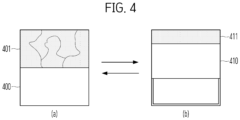
- FIG. 4 illustrates the exterior of a TV according to another embodiment of the disclosure.
- the TV screen does not necessarily have to use a material enabling a flexible display, and a regular TV screen may be used in the embodiment of FIG. 4 .
- a cover 400 of the same or similar size is designed to be located under a TV screen 401, as illustrated in FIG. 4(a) .
- a specific condition e.g., when a signal from pressing a power button on a remote control once is applied
- a cover 410 is designed to move in an upward direction, exposing only a portion of a TV screen 411, as illustrated in FIG. 4(b) .
- a motor is designed to be located around the cover.
- a TV designed as illustrated in FIG. 4 may be defined as an atelier TV
- the mode illustrated in FIG. 4(a) may be defined as a full view
- the mode illustrated in FIG. 4(b) may be defined as a line view.
- FIG. 5 illustrates the exterior of a TV according to another embodiment of the disclosure.
- a TV screen does not necessarily need to be made of a material enabling a flexible display, and a regular TV screen may be used.
- FIG. 5 differs from FIG. 4 in that the TV screen is moved instead of the cover.
- a cover 500 of the same or similar size is designed to be located under a TV screen 501.
- the TV screen 501 and the cover 500 are spaced apart from each other by a specific distance to prevent friction between them.
- a specific condition e.g., when a signal from pressing a power button on a remote control once is applied
- a TV screen 511 is designed to move in the upward direction to be fully exposed, as illustrated in FIG. 5(b) .
- a cover 510 does not move.
- a TV designed as illustrated in FIG. 5 may be defined as an interior TV, the mode illustrated in FIG. 5(a) may be defined as a partial view, and the mode illustrated in FIG. 5(b) may be defined as a full view.
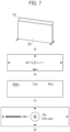
- FIG. 6 illustrates a motor for adjusting a screen size of a TV according to an embodiment of the disclosure.
- FIG. 6 will be described based on the assumption that the motor is applied to the TV of FIG. 3 , for ease of description.
- FIG. 6(a) is an oblique view illustrating the housing and the TV screen of FIG. 3 .
- FIG. 6(b) illustrates a cross-section cut along line A-A' in FIG. 6(a) .
- a TV system 100 may further include a housing 10.
- the housing 10 may be configured to accommodate various components, and more specifically, for example, a screen 30 and various electronic components for operating the screen 30.
- the TV system 100 may further include a roller 20 rotatably installed within the housing 10, as illustrated in FIG. 6(b) .
- the roller 20 may include sleeves formed at both ends thereof, and these sleeves may be rotatably supported with respect to the housing 10 by bearings.
- roller 20 may also be connected to a motor 21 installed within the housing 10 and rotated by the motor 21 in a clockwise direction R1 or counterclockwise direction R2, as illustrated. Further, a gear train may be interposed between the motor 21 and the roller 20 in order to adjust a rotation speed of the roller 20.
- the TV system 100 may include the screen 30 configured to display various types of content and information related to the content.
- the screen 30 may display video content, audio content, and other auxiliary content.
- the content may include various pieces of information associated with the content, such as the running time of video content, the title of content, and so on.
- the screen 30 may be accommodated within the housing 10 so that the TV system 100 may have a compact structure, as illustrated.
- the screen 30 may basically need to be deformed. Therefore, the TV system 100 may use a flexible display as the screen 30.
- the screen 30 may be rolled around the roller 20, as illustrated in FIG. 6(b) . Further, depending on a rotation direction of the roller 20, the screen 30 may be wound on the roller 20 or unwound from the roller 20. As the screen 30 is unwound from the roller 20, the screen 30 may be projected or expanded/rolled out to the outside of the housing 10. Conversely, as the screen 30 is wound onto the roller 20, the screen 30 may be retracted/rolled into the housing 10. More specifically, as illustrated in FIG. 6(b) , when the roller 20 is rotated in the clockwise direction R1, the screen 30 may be unwound from the roller 20 and expanded to the outside of the housing 10 through an opening 11 formed on the housing 10.
- the screen that was accommodated within the housing 300 in FIG. 3(a) may be expanded to the outside of the housing 310 and form the screen 311 of a predetermined size, as illustrated in FIG. 3(b).
- the screen 30 may be further released from the roller 20. Accordingly, the screen may be projected to the outside of the housing 10 to a larger size, and form a screen of a larger size, as illustrated in FIG. 3(c).
- the screen 30 may be wound on the roller 20 and retracted into the housing 10 through the opening 11. Accordingly, the screen 321 of FIG.
- 3(c) may be retracted into the housing 310 to have a smaller size, thereby forming the screen of the smaller size, as illustrated in FIG. 3(b). Further, as the roller 20 is further rotated in the counterclockwise direction R2, the screen 30 may be further wound onto the roller 20. Thus, the screen may not be projected to the outside of the housing 300, and may be fully accommodated within the housing 300, as illustrated in FIG. 3(a).
- the front of the expanded screen 30 may be protected by a window, while the rear of the screen 30 may be exposed. Since the screen 30 includes sensitive electronic components and substrates, it should be appropriately protected to prevent failure. Accordingly, as illustrated in FIG. 6(b) , the TV system 100 may include a cover 40 configured to cover the rear of the expanded screen 30.
- the cover 40 may include a plurality of interconnected links. Further, the links may have a width corresponding to a width of the screen 30, and the interconnected links, that is, the cover 40 may form a single plate covering the rear of the screen 30. Since any one of the links may be pivotable with respect to any other neighboring link, the cover 40 may be wound on a first roller 41 and guided up to the rear of the screen 30 by a second roller 42.
- the first roller 41 may rotate to unwind the cover 40.
- the unwound cover 40 is then attached to the rear of the screen 30, while being guided by the second roller 41. Accordingly, as the cover 40 is expanded to the outside of the housing 10 along with the screen 30, the cover 40 may protect the rear of the screen 30.
- the first roller 41 when the screen 30 is retracted, the first roller 41 may rotate in an opposite direction to separate the cover 40 from the screen 30, and the separated cover 40 may be wound on the first roller 41, while being guided by the second roller 42.
- the first roller 41 In the cover 40, the first roller 41 may be driven along with the roller 20 by the motor 21, and a separate motor for driving the first roller 41 may also be installed within the housing 10.
- the TV system 100 may include a support 50 configured to support the expanded screen 30.
- the support 50 may be expanded to the outside of the housing 10 through the opening 11 by a motor 51 and an auxiliary support 52 connected to the support 50. Accordingly, the support 50 may be expanded together with the screen 30 to the outside of the housing 10. Therefore, the screen 30 expanded by the support 50 may display content to a user, while being stably supported.
- FIG. 7 illustrates an embodiment in which with a portion of a screen of a TV exposed, different content is displayed to a different user according to an embodiment of the disclosure.
- TVs illustrated in FIGS. 7 to 15 correspond to the afore-described TV of FIG. 5
- the disclosure is not necessarily limited thereto, and the same thing is equally applicable to the TV illustrated in FIG. 3 or 4 , which is capable of selectively exposing a portion or all of a screen.
- a TV controls a motor to expose only a portion 710 of a screen. Then, with only the portion 710 of the screen exposed, the TV displays any content (e.g., current time information and weather information, and so on). The remaining portion of the screen except for the exposed portion 710 of the screen remains covered by a cover 720. Unlike a conventional TV, the state illustrated in FIG. 7 may be referred to as a partial view, as described above.
- the TV when the TV according to an embodiment of the disclosure detects a specific event (e.g., a specific user is located in the vicinity of the TV or when it is estimated that a specific user intends to control the TV), the TV displays content customized for the user on the exposed portion 711 of the screen, while maintaining the partial view (i.e., the state in which the cover 721 covers the screen partially).
- the customized content may correspond to, for example, a favorite application (e.g., an application related to news, fitness, or music) preset by the specific user.
- the favorite application may be automatically generated by the TV based on a device usage history of the user or time information.
- one of the main features of the disclosure is a technique of automatically switching from the mode illustrated in FIG. 7(a) to the mode illustrated FIG. 7(b) , after more accurately detecting a specific user located in the vicinity of the TV. This will be described in more detail below with reference to FIGS. 8 to 10 .
- FIG. 8 separately illustrates a case in which with a portion of a screen of a TV exposed, a user holding a remote control or a portable phone is in proximity according to an embodiment of the disclosure.
- the size of an exposed screen of a TV is changed by a motor.
- the TV controls the motor to expose only a portion 810 of a screen.
- an unexposed portion of the TV screen is covered by a cover 820. Accordingly, power does not need to be supplied unnecessarily to the entire TV screen.
- any content may be displayed.
- the TV starts shooting through a camera installed on the TV or outside of the TV.
- the first data is used, for example, to distinguish between two situations.
- the first data includes information for detecting whether the remote control has been moved.
- the first data includes information for identifying whether the portable phone is in proximity to the TV.
- Table 1 A database including the first data in the memory is illustrated as Table 1. [Table 1].
- Type of communicatively connected external device Criterion for determining specific condition Portable phone type Determine whether the device is in close proximity based on signal strength
- Remote control type Determine whether the remote control moves by motion detection sensor
- the TV identifies a specific user in the vicinity of the TV, referring to second data stored in the memory and the result of the above shooting.
- the second data may include, for example, facial feature information about pre-captured users (e.g., family members of a house where the TV is installed).
- pre-captured users e.g., family members of a house where the TV is installed.
- the TV changes content displayed with only the 810 portion of the screen exposed or controls the motor to expose all of the screen, according to the identified specific user.
- FIG. 8(b) is based on the assumption that a user 830 holding a remote control 831 is located in the vicinity of the TV. In this case, the content displayed on the portion 810 of the screen is automatically changed. A specific data processing scheme for implementing this will be described in more detail with reference to FIG. 9 below.
- FIG. 8(c) is based on the assumption that a user 840 holding a portable phone 841 is located in the vicinity of the TV. In this case, content displayed on the portion 810 of the screen is automatically changed. A specific data processing scheme for implementing this will be described in more detail with reference to FIG. 10 below.
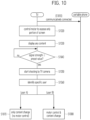
- FIG. 9 is a flowchart illustrating processing of related data by a TV, when the user holds the remote control in FIG. 8 .
- the TV controls the motor to expose only a portion of the screen (S910). Further, the TV displays any content, while only the portion of the screen is exposed (S920).
- the TV starts shooting through the camera installed on the TV (S950).
- an external device e.g., the remote control
- the remote control and the TV are wirelessly connected to each other by short-range communication, such as Bluetooth.
- the remote control determines that the specific condition is satisfied, and transmits a trigger signal to the TV to instruct the TV to start shooting by the TV camera (S940).
- the TV identifies a specific user, referring to the second data stored in the memory (as described above with reference to FIG. 8 ) and a result of the shooting (S960).
- the TV changes the content displayed with only the portion of the screen exposed (S970) or controls the motor to expose all of the screen (S980).
- the motor is not controlled for the specific user who has moved the remote control in the vicinity of the TV in step S970, thereby meeting user needs and reducing power consumption caused by unnecessary motor control.
- FIG. 10 is a flowchart illustrating processing of related data by a TV, when the user holds the portable phone in FIG. 8 .
- the TV according to an embodiment of the disclosure and the portable phone are wirelessly connected to each other through short-range communication, such as Bluetooth.
- the TV controls the motor to expose only a portion of the screen (S1020). Further, with only the portion of the screen exposed, the TV displays any content (S1030).
- the TV determines whether the strength of a signal transmitted to and received from the portable phone is equal to or greater than a preset threshold (S1040).
- the TV estimates that a user is located in the vicinity, and starts shooting by controlling the camera installed on the TV or the external camera (S1050).
- the TV identifies the specific user, referring to the second data stored in the memory (as described above with reference to FIG. 8 ) and a result of the above shooting (S1060).
- the TV changes the content displayed with only the portion of the screen exposed (S1070) or controls the motor to expose the entire screen (S1080).
- the motor is not controlled for a specific user who has moved the remote control in the vicinity of the TV in step S1070, thereby meeting user needs and reducing power consumption caused by unnecessary motor control.
- the signal strength determination S1040 and the camera shooting S1050 have been described as a solution for identifying a user carrying a portable phone in the vicinity of the TV according to an embodiment of the disclosure.
- This design has the technical effect of identifying a case in which user B is in the vicinity of the TV, carrying a portable phone that user A owns.
- FIGS. 7 to 10 it has been mainly described that a user located in the vicinity of the TV according to an embodiment of the disclosure is identified, and a favorite application or the like is displayed in a partial view of a TV screen according to the identified user.
- a different condition e.g., a life cycle or the like
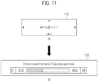
- FIG. 11 illustrates an embodiment in which content displayed on a portion of a screen of a TV is changed based on user history information.
- the TV receives schedule information or history information about a user from an external device (e.g., a portable phone), a cloud server, or the like.
- an external device e.g., a portable phone
- a cloud server e.g., a cloud server
- a specific user sets a schedule on a portable phone to work from home starting at 7:00 a.m. every day, and transmits the information to the TV directly or through a server or the like.
- time information and date information are displayed on a portion 1110 of a screen of the TV, as illustrated in FIG. 11(a) .
- FIG. 11 While not shown in FIG. 11 , when the specific user moves away from the TV, carrying the portable phone, the basic information illustrated in FIG. 11(a) is again displayed. However, this may be applicable, only when the presence of the specific user in the vicinity of the TV is determined based on the strength of communication with the portable phone, not based on movement of the remote control.
- FIG. 12 illustrates an embodiment in which content displayed on a portion of a screen of a TV is changed based on exercise information obtained from an external device.
- a remote control and a portable phone have been exemplarily described as external devices for determining the location of a user in the vicinity of a TV according to an embodiment of the disclosure.
- the disclosure may also be extended to a case in which a user wearing a wearable device (e.g., a watch or the like) is located in the vicinity of a TV.
- time information and date information are displayed on a portion 1210 of the screen of the TV, as illustrated in FIG. 12(a) .
- content based on exercise information about the specific user is designed to be displayed on a portion 1220 of the screen of the TV, as illustrated in FIG. 12(b) .
- the TV again displays the basic information illustrated in FIG. 12(a) .
- FIG. 13 illustrates an embodiment in which content displayed on a portion of a screen of a TV is changed based on identified user information.
- FIG. 14 illustrates an embodiment of changing the size of an exposed screen of a TV based on identified user information.
- FIGS. 13 and 14 are based on the assumption that the same user is detected in the vicinity of the TV according to an embodiment of the disclosure. However, even when the same user is detected, the TV according to an embodiment of the disclosure may or may not control the motor.
- the TV identifies the user in the vicinity of the TV through the camera, as described above, and stores a TV usage history of the user by time in a database in the memory.
- only basic information e.g., time information, date information, and so on
- a portion 1310 of a screen exposed a partial view
- the remaining portion of the screen of the TV is covered by a cover 1320.
- the TV Upon detection of specific user A between 7:00 a.m. and 8:00 a.m., the TV briefly displays news or stock information in the form of tickers on a portion 1311 of a screen in the TV, as illustrated in FIG. 13(b) . However, as in FIG. 13(a) , a cover 1321 maintains the partial view in which it covers the remaining area of the TV screen.
- this offers the technical effect of minimizing power consumption by not controlling the motor based on the time zone-based TV usage history of user A.
- FIG. 14(a) only the basic information (e.g., time information, date information, and so on) is displayed with a portion 1410 of a screen exposed (a partial view), in the TV according to an embodiment of the disclosure.
- the other portion of the screen of the TV is covered by a cover 1420.
- FIG. 14 differs from FIG. 13 in that the former is based on the assumption that the same user A is detected by the TV between 7:00 p.m. and 8:00 p.m.
- the TV controls a tuner to attempt to switch to any channel (or a preferred channel set by user A), while simultaneously controlling the motor to expand the screen as much as possible to a full view 1411.
- a cover 1421 does not cover the TV screen at all in FIG. 14(b) .
- user-desired content may be advantageously provided on a large screen by controlling the motor based on the time zone-based TV usage history of the user.
- the TV according to an embodiment of the disclosure is capable of comparing the third data stored in the memory with current time and depending on the result of the comparison, controlling the motor to expose all or only a portion of the TV screen while executing a specific application.
- the third data may refer to, for example, data in which the history of using the TV according to an embodiment of the disclosure by a specific user is mapped to time information.
- FIG. 15 illustrates an embodiment of changing the size of an exposed screen of a TV based on communication with a portable phone.
- the TV displays time information and weather information, with only a portion 1510 of the screen exposed.
- the TV screen except for the exposed area maintains a partial view in which it is covered by a cover 1520.
- the TV screen When a user with a portable phone is in close proximity to the TV according to an embodiment of the disclosure, only some of applications of the communicatively connected portable phone are displayed on a portion 1511 of the TV screen, which is not covered by a cover 1521, as illustrated in FIG. 15(b) .
- the applications displayed on the portion 1511 of the TV screen may be preset by the user or may be automatically filtered to frequently used applications.
- a notification message indicating that the application is connecting is displayed on a portion 1512 of the TV screen, as illustrated in FIG. 15(c) , and at this time, the partial view is still maintained, in which a cover 1522 partially covers the TV screen.
- the TV controls the motor to expose an entire screen 1513, leaving no area of the screen covered by a cover 1523, as illustrated in FIG. 15(d) .
- the TV according to an embodiment of the disclosure, for example, to further determine whether to maintain the partial view or switch to the full view, depending on the type of the selected application in step (c) of FIG. 15 .
- a design is made such that for example, when the selected application of the portable phone is suitable for display on a small-sized screen, the partial view is maintained, whereas only when the selected application of the portable phone is suitable for display on a large-sized screen, the partial view is switched to the full view. Accordingly, there is the technical effect of reducing unnecessary motor control and consequently power consumption.
- the disclosure is applicable to TVs of various form factors including, for example, a rollable TV, and acknowledged to have industrial applicability.
Landscapes
- Engineering & Computer Science (AREA)
- Multimedia (AREA)
- Signal Processing (AREA)
- Databases & Information Systems (AREA)
- Health & Medical Sciences (AREA)
- General Health & Medical Sciences (AREA)
- Social Psychology (AREA)
- Human Computer Interaction (AREA)
- Theoretical Computer Science (AREA)
- Computer Networks & Wireless Communication (AREA)
- General Physics & Mathematics (AREA)
- Physics & Mathematics (AREA)
- Computer Hardware Design (AREA)
- General Engineering & Computer Science (AREA)
- Biomedical Technology (AREA)
- Selective Calling Equipment (AREA)
Applications Claiming Priority (1)
| Application Number | Priority Date | Filing Date | Title |
|---|---|---|---|
| PCT/KR2021/015313 WO2023074945A1 (ko) | 2021-10-28 | 2021-10-28 | Tv 및 그 제어 방법 |
Publications (2)
| Publication Number | Publication Date |
|---|---|
| EP4425909A1 true EP4425909A1 (de) | 2024-09-04 |
| EP4425909A4 EP4425909A4 (de) | 2025-08-20 |
Family
ID=86158151
Family Applications (1)
| Application Number | Title | Priority Date | Filing Date |
|---|---|---|---|
| EP21962569.6A Pending EP4425909A4 (de) | 2021-10-28 | 2021-10-28 | Fernseher und steuerungsverfahren dafür |
Country Status (4)
| Country | Link |
|---|---|
| US (1) | US12556647B2 (de) |
| EP (1) | EP4425909A4 (de) |
| KR (1) | KR20240038992A (de) |
| WO (1) | WO2023074945A1 (de) |
Families Citing this family (1)
| Publication number | Priority date | Publication date | Assignee | Title |
|---|---|---|---|---|
| DE112022005765T5 (de) * | 2022-01-04 | 2024-10-02 | LG Electronics Inc. | Fernseher und Steuerverfahren dafür |
Family Cites Families (25)
| Publication number | Priority date | Publication date | Assignee | Title |
|---|---|---|---|---|
| JP2010277197A (ja) * | 2009-05-26 | 2010-12-09 | Sony Corp | 情報処理装置、情報処理方法およびプログラム |
| JP5796849B2 (ja) | 2009-09-23 | 2015-10-21 | ロヴィ ガイズ, インコーポレイテッド | メディアデバイスの検出領域内のユーザの自動的に検出するシステムおよび方法 |
| US20120029812A1 (en) * | 2010-07-29 | 2012-02-02 | King Abdul Aziz City For Science And Technology | Method and system for automatically planning and scheduling a remote sensing satellite mission |
| EP2418866A3 (de) * | 2010-08-11 | 2014-05-21 | LG Electronics Inc. | Verfahren zum Betrieb einer Bildanzeigevorrichtung |
| KR20120019326A (ko) | 2010-08-25 | 2012-03-06 | 엘지전자 주식회사 | 디스플레이 장치 및 그의 동작 제어방법 |
| EP2818986A1 (de) * | 2013-06-28 | 2014-12-31 | Nokia Corporation | Schwebendes Feld |
| WO2016016675A1 (en) * | 2014-07-29 | 2016-02-04 | Umm Al-Qura University | Oled multi-use intelligent curtain and method |
| US20160119438A1 (en) * | 2014-10-23 | 2016-04-28 | Google Inc. | Systems and methods of sharing media and data content across devices through local proximity |
| KR102420043B1 (ko) | 2015-04-16 | 2022-07-13 | 삼성전자주식회사 | 디스플레이 장치 및 디스플레이 방법 |
| KR20160123620A (ko) * | 2015-04-16 | 2016-10-26 | 삼성전자주식회사 | 디스플레이 장치 및 디스플레이 방법 |
| KR102336984B1 (ko) | 2015-07-09 | 2021-12-08 | 엘지전자 주식회사 | 멀티미디어 디바이스 |
| KR102469625B1 (ko) * | 2015-10-13 | 2022-11-22 | 엘지전자 주식회사 | 디스플레이 디바이스 |
| KR20170057056A (ko) * | 2015-11-16 | 2017-05-24 | 삼성전자주식회사 | 원격제어장치, 원격제어장치의 구동방법, 영상표시장치, 영상표시장치의 구동방법 및 컴퓨터 판독가능 기록매체 |
| KR102402837B1 (ko) * | 2015-12-07 | 2022-05-27 | 엘지전자 주식회사 | 디스플레이 장치 |
| CN106205390B (zh) * | 2016-07-08 | 2018-03-27 | 广东欧珀移动通信有限公司 | 一种电子设备控制方法及电子设备 |
| KR102594900B1 (ko) | 2016-07-13 | 2023-10-27 | 엘지전자 주식회사 | 디스플레이 디바이스 및 모바일 디바이스 |
| KR102420877B1 (ko) * | 2017-08-25 | 2022-07-13 | 엘지전자 주식회사 | 영상표시장치 |
| KR102395243B1 (ko) * | 2017-09-26 | 2022-05-06 | 삼성전자주식회사 | 전자 장치 및 이의 제어방법 |
| CN112991928B (zh) * | 2019-12-13 | 2022-08-16 | Oppo广东移动通信有限公司 | 电子装置 |
| KR102711601B1 (ko) | 2019-12-13 | 2024-09-30 | 엘지전자 주식회사 | 스마트 월 및 그 제어 방법 |
| KR102914016B1 (ko) | 2019-12-31 | 2026-01-16 | 삼성전자주식회사 | 디스플레이 장치 및 그 제어 방법 |
| CN114461021B (zh) * | 2022-01-29 | 2024-09-17 | 联想(北京)有限公司 | 一种电子设备 |
| WO2023158216A1 (ko) * | 2022-02-16 | 2023-08-24 | 삼성전자 주식회사 | 컨텐츠 디스플레의 영역의 비율에 대응하도록 플렉서블 디스플레이의 노출 영역의 크기를 제어하는 전자 장치 및 그 제어 방법 |
| WO2023177071A1 (ko) * | 2022-03-17 | 2023-09-21 | 삼성전자 주식회사 | 플렉서블 디스플레이를 포함하는 전자 장치 및 그 동작 방법 |
| TWI857803B (zh) * | 2023-10-04 | 2024-10-01 | 宏碁股份有限公司 | 具可撓式顯示面板的可攜式電腦 |
-
2021
- 2021-10-28 KR KR1020247005523A patent/KR20240038992A/ko active Pending
- 2021-10-28 WO PCT/KR2021/015313 patent/WO2023074945A1/ko not_active Ceased
- 2021-10-28 US US18/699,867 patent/US12556647B2/en active Active
- 2021-10-28 EP EP21962569.6A patent/EP4425909A4/de active Pending
Also Published As
| Publication number | Publication date |
|---|---|
| US20240406341A1 (en) | 2024-12-05 |
| WO2023074945A1 (ko) | 2023-05-04 |
| EP4425909A4 (de) | 2025-08-20 |
| US12556647B2 (en) | 2026-02-17 |
| KR20240038992A (ko) | 2024-03-26 |
Similar Documents
| Publication | Publication Date | Title |
|---|---|---|
| CN107018434B (zh) | 包括数字设备和外部设备的系统及其处理数据的方法 | |
| US20160127640A1 (en) | Power saving control method and electronic device supporting the same | |
| KR20150069355A (ko) | 디스플레이 디바이스 및 그 제어 방법 | |
| US20100013997A1 (en) | Metadata display control method and system for broadcast receiver | |
| US10324595B2 (en) | Digital device configured to connect with plurality of operation devices and method of displaying second user interface associated with second operation device in response to dragging of first user interface associated with first operation device in the same | |
| CN112911355B (zh) | 显示装置 | |
| KR20150084145A (ko) | 디스플레이 디바이스 및 그 제어 방법 | |
| US20210168431A1 (en) | Display apparatus and method of controlling the same | |
| US8813148B2 (en) | Data supply device, data output device, data output system, data display system, data supply method, data output method, and program | |
| US12556647B2 (en) | TV and control method thereof | |
| JP2005150831A (ja) | Tv受信及びリモコン機能付き携帯電話機 | |
| US12563254B2 (en) | TV and control method therefor | |
| KR102102748B1 (ko) | 전자 장치, 외부 장치 및 전자 장치의 외부 장치 전원 제어방법 | |
| JP2005109828A5 (de) | ||
| JP2007006457A (ja) | デジタルデータ受信装置 | |
| US12477182B2 (en) | TV and method for controlling same | |
| JP5073374B2 (ja) | 情報処理装置、情報処理装置の制御方法、制御プログラム、および、記録媒体 | |
| KR20070006789A (ko) | 시청각 디스플레이 장치, 방송 신호 수신 및 디스플레이방법 | |
| EP4456541A1 (de) | Fernseher und steuerungsverfahren dafür | |
| JP2005117172A (ja) | 電子機器 | |
| EP4429227A1 (de) | Fernseher und steuerungsverfahren dafür | |
| KR101239950B1 (ko) | 이동통신기기와 디지털 tv 간의 tv 방송 프로그램 연계 시청방법과, 그 이동통신기기 및 디지털 tv | |
| JP4142555B2 (ja) | データ伝送システム | |
| JP4966573B2 (ja) | 放送受信装置、放送受信方法及び放送受信プログラム | |
| JP4399487B2 (ja) | データ供給装置、データ出力装置、データ出力システム、データ供給方法、データ出力方法、及びプログラム |
Legal Events
| Date | Code | Title | Description |
|---|---|---|---|
| STAA | Information on the status of an ep patent application or granted ep patent |
Free format text: STATUS: THE INTERNATIONAL PUBLICATION HAS BEEN MADE |
|
| PUAI | Public reference made under article 153(3) epc to a published international application that has entered the european phase |
Free format text: ORIGINAL CODE: 0009012 |
|
| STAA | Information on the status of an ep patent application or granted ep patent |
Free format text: STATUS: REQUEST FOR EXAMINATION WAS MADE |
|
| 17P | Request for examination filed |
Effective date: 20240522 |
|
| AK | Designated contracting states |
Kind code of ref document: A1 Designated state(s): AL AT BE BG CH CY CZ DE DK EE ES FI FR GB GR HR HU IE IS IT LI LT LU LV MC MK MT NL NO PL PT RO RS SE SI SK SM TR |
|
| DAV | Request for validation of the european patent (deleted) | ||
| DAX | Request for extension of the european patent (deleted) | ||
| A4 | Supplementary search report drawn up and despatched |
Effective date: 20250718 |
|
| RIC1 | Information provided on ipc code assigned before grant |
Ipc: H04N 5/64 20060101AFI20250714BHEP Ipc: H04N 21/45 20110101ALI20250714BHEP Ipc: H04N 21/422 20110101ALI20250714BHEP Ipc: H04N 21/4223 20110101ALI20250714BHEP Ipc: H04N 21/4363 20110101ALI20250714BHEP Ipc: H04N 23/00 20230101ALI20250714BHEP Ipc: G06F 1/16 20060101ALI20250714BHEP Ipc: G09F 9/30 20060101ALI20250714BHEP Ipc: H04N 21/4415 20110101ALI20250714BHEP Ipc: H04N 21/442 20110101ALI20250714BHEP |
|
| STAA | Information on the status of an ep patent application or granted ep patent |
Free format text: STATUS: EXAMINATION IS IN PROGRESS |