EP4456541A1 - Fernseher und steuerungsverfahren dafür - Google Patents
Fernseher und steuerungsverfahren dafür Download PDFInfo
- Publication number
- EP4456541A1 EP4456541A1 EP22918913.9A EP22918913A EP4456541A1 EP 4456541 A1 EP4456541 A1 EP 4456541A1 EP 22918913 A EP22918913 A EP 22918913A EP 4456541 A1 EP4456541 A1 EP 4456541A1
- Authority
- EP
- European Patent Office
- Prior art keywords
- screen
- view mode
- video
- user
- present disclosure
- Prior art date
- Legal status (The legal status is an assumption and is not a legal conclusion. Google has not performed a legal analysis and makes no representation as to the accuracy of the status listed.)
- Pending
Links
Images


Classifications
-
- H—ELECTRICITY
- H04—ELECTRIC COMMUNICATION TECHNIQUE
- H04N—PICTORIAL COMMUNICATION, e.g. TELEVISION
- H04N21/00—Selective content distribution, e.g. interactive television or video on demand [VOD]
- H04N21/40—Client devices specifically adapted for the reception of or interaction with content, e.g. set-top-box [STB]; Operations thereof
- H04N21/43—Processing of content or additional data, e.g. demultiplexing additional data from a digital video stream; Elementary client operations, e.g. monitoring of home network or synchronising decoder's clock; Client middleware
- H04N21/431—Generation of visual interfaces for content selection or interaction; Content or additional data rendering
- H04N21/4318—Generation of visual interfaces for content selection or interaction; Content or additional data rendering by altering the content in the rendering process, e.g. blanking, blurring or masking an image region
-
- G—PHYSICS
- G06—COMPUTING OR CALCULATING; COUNTING
- G06F—ELECTRIC DIGITAL DATA PROCESSING
- G06F1/00—Details not covered by groups G06F3/00 - G06F13/00 and G06F21/00
- G06F1/16—Constructional details or arrangements
- G06F1/1613—Constructional details or arrangements for portable computers
- G06F1/1633—Constructional details or arrangements of portable computers not specific to the type of enclosures covered by groups G06F1/1615 - G06F1/1626
- G06F1/1637—Details related to the display arrangement, including those related to the mounting of the display in the housing
- G06F1/1652—Details related to the display arrangement, including those related to the mounting of the display in the housing the display being flexible, e.g. mimicking a sheet of paper, or rollable
-
- G—PHYSICS
- G06—COMPUTING OR CALCULATING; COUNTING
- G06F—ELECTRIC DIGITAL DATA PROCESSING
- G06F1/00—Details not covered by groups G06F3/00 - G06F13/00 and G06F21/00
- G06F1/16—Constructional details or arrangements
- G06F1/1613—Constructional details or arrangements for portable computers
- G06F1/1633—Constructional details or arrangements of portable computers not specific to the type of enclosures covered by groups G06F1/1615 - G06F1/1626
- G06F1/1675—Miscellaneous details related to the relative movement between the different enclosures or enclosure parts
- G06F1/1677—Miscellaneous details related to the relative movement between the different enclosures or enclosure parts for detecting open or closed state or particular intermediate positions assumed by movable parts of the enclosure, e.g. detection of display lid position with respect to main body in a laptop, detection of opening of the cover of battery compartment
-
- G—PHYSICS
- G06—COMPUTING OR CALCULATING; COUNTING
- G06F—ELECTRIC DIGITAL DATA PROCESSING
- G06F1/00—Details not covered by groups G06F3/00 - G06F13/00 and G06F21/00
- G06F1/26—Power supply means, e.g. regulation thereof
- G06F1/32—Means for saving power
- G06F1/3203—Power management, i.e. event-based initiation of a power-saving mode
- G06F1/3206—Monitoring of events, devices or parameters that trigger a change in power modality
- G06F1/3231—Monitoring the presence, absence or movement of users
-
- G—PHYSICS
- G06—COMPUTING OR CALCULATING; COUNTING
- G06F—ELECTRIC DIGITAL DATA PROCESSING
- G06F1/00—Details not covered by groups G06F3/00 - G06F13/00 and G06F21/00
- G06F1/26—Power supply means, e.g. regulation thereof
- G06F1/32—Means for saving power
- G06F1/3203—Power management, i.e. event-based initiation of a power-saving mode
- G06F1/3234—Power saving characterised by the action undertaken
- G06F1/325—Power saving in peripheral device
- G06F1/3265—Power saving in display device
-
- H—ELECTRICITY
- H04—ELECTRIC COMMUNICATION TECHNIQUE
- H04N—PICTORIAL COMMUNICATION, e.g. TELEVISION
- H04N21/00—Selective content distribution, e.g. interactive television or video on demand [VOD]
- H04N21/40—Client devices specifically adapted for the reception of or interaction with content, e.g. set-top-box [STB]; Operations thereof
- H04N21/41—Structure of client; Structure of client peripherals
- H04N21/422—Input-only peripherals, i.e. input devices connected to specially adapted client devices, e.g. global positioning system [GPS]
- H04N21/42202—Input-only peripherals, i.e. input devices connected to specially adapted client devices, e.g. global positioning system [GPS] environmental sensors, e.g. for detecting temperature, luminosity, pressure, earthquakes
-
- H—ELECTRICITY
- H04—ELECTRIC COMMUNICATION TECHNIQUE
- H04N—PICTORIAL COMMUNICATION, e.g. TELEVISION
- H04N21/00—Selective content distribution, e.g. interactive television or video on demand [VOD]
- H04N21/40—Client devices specifically adapted for the reception of or interaction with content, e.g. set-top-box [STB]; Operations thereof
- H04N21/43—Processing of content or additional data, e.g. demultiplexing additional data from a digital video stream; Elementary client operations, e.g. monitoring of home network or synchronising decoder's clock; Client middleware
- H04N21/442—Monitoring of processes or resources, e.g. detecting the failure of a recording device, monitoring the downstream bandwidth, the number of times a movie has been viewed, the storage space available from the internal hard disk
- H04N21/44213—Monitoring of end-user related data
- H04N21/44218—Detecting physical presence or behaviour of the user, e.g. using sensors to detect if the user is leaving the room or changes his face expression during a TV programme
-
- H—ELECTRICITY
- H04—ELECTRIC COMMUNICATION TECHNIQUE
- H04N—PICTORIAL COMMUNICATION, e.g. TELEVISION
- H04N21/00—Selective content distribution, e.g. interactive television or video on demand [VOD]
- H04N21/80—Generation or processing of content or additional data by content creator independently of the distribution process; Content per se
- H04N21/85—Assembly of content; Generation of multimedia applications
- H04N21/854—Content authoring
- H04N21/8549—Creating video summaries, e.g. movie trailer
-
- H—ELECTRICITY
- H04—ELECTRIC COMMUNICATION TECHNIQUE
- H04N—PICTORIAL COMMUNICATION, e.g. TELEVISION
- H04N5/00—Details of television systems
- H04N5/44—Receiver circuitry for the reception of television signals according to analogue transmission standards
- H04N5/57—Control of contrast or brightness
-
- H—ELECTRICITY
- H04—ELECTRIC COMMUNICATION TECHNIQUE
- H04N—PICTORIAL COMMUNICATION, e.g. TELEVISION
- H04N5/00—Details of television systems
- H04N5/64—Constructional details of receivers, e.g. cabinets or dust covers
Definitions
- the technical field of the present disclosure includes various multimedia devices having displays, etc. For example, it is applicable to a Television (TV) having a variable size of an exposed screen.
- TV Television
- One technical task of the present disclosure is to provide a system that selectively allows a screen to be partially or fully exposed by using a motor or the like added to a TV.
- Another technical task of the present disclosure is to provide a solution for minimizing an afterimage and a burn-in phenomenon in a TV having a variable size of an exposed screen.
- a method of controlling a TV with a screen having an exposed size changed by a motor including displaying a video in black-and-white in a first view mode, displaying the video in color based on sensing at least one user in the first view mode, lowering a brightness of the video based on failing in sensing the at least one user, and controlling the video to be displayed in the black-and-white again.
- a TV having a variable exposed size of a screen
- the TV including a sensor configured to sense at least one user, a display configured to display a video in color based on sensing the at least one user while displaying the video in black-and-white in a first view mode, and a controller configured to lower a brightness of the video and display the video in the black-and-white again based on failing in sensing the at least one user.
- a system for selectively allowing a screen to be partially or fully exposed using a motor or the like added to a TV is provided.
- FIG. 1 is a diagram illustrating components inside a TV according to an embodiment of the present disclosure.
- the present disclosure is applicable to various TV products, for example, the Digital Video Broadcasting (DVB) standard, which is a European standard, the Advanced Television Systems Committee (ATSC) 3.0 standard, which is a North American/Korean standard, etc.
- DVD Digital Video Broadcasting
- ATSC Advanced Television Systems Committee
- FIG. 1 a process for a TV 100 to perform and initial service scan operation in accordance with the ATSC 3.0 standard will be illustrated, but the scope of the rights of the present disclosure should be determined according to the matters described in the claims.
- a tuner 110 determines whether a signal is present by using a predefined frequency list. If a signal is detected at a given frequency, a baseband processor 120 extracts L1 signaling of a preamble.
- the baseband processor 120 transmits Physical Layer Pipe (PLP) data including link layer signaling and Low Level Signaling (LLS) to a middleware 130, and the middleware 130 may extract the link layer signaling and the LLS from the PLP data.
- PLP Physical Layer Pipe
- LLS Low Level Signaling
- the middleware 130 includes a signaling manager 140 and a channel manager 150.
- the middleware 130 receives the PLP data including the link layer signaling and the LLS from the baseband processor 120 and passes the data to an appropriate parser.
- the middleware 130 extracts Link Mapping Table (LMT) from the link layer signaling and passes the LMT to an LMT parser 141. Furthermore, the middleware 130 extracts Service List Table (SLT) from the LLS and passes the SLT to an SLT parser 142.
- LMT Link Mapping Table
- SLT Service List Table
- the LMT parser 141 parses the LMT and extracts first information (e.g., PLPID, session information (IP address and port number), etc.) necessary to generate a channel map.
- first information e.g., PLPID, session information (IP address and port number), etc.
- the SLT parser 142 parses the SLT and extracts second information (e.g., service id, service name, etc.) necessary to generate the channel map.
- second information e.g., service id, service name, etc.
- the extracted first information and second information are stored in a channel map 151.
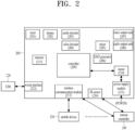
- FIG. 2 shows components inside a TV and an external device according to another embodiment of the present disclosure.
- Those skilled in the art may implement the present disclosure by combining some components with reference to FIGS. 1 and 2 .
- the baseband processor 120 and the middleware 130 shown in FIG. 1 may be included in a controller 209 shown in FIG. 2 .
- a TV 200 shown in FIG. 2 includes various components, the scope of the rights of the present disclosure is not limited thereto and should be determined according to the matters described in the claims.
- the components inside the TV 200 shown in FIG. 2 may be controlled through the controller 209, and each of the components may be directly or indirectly connected thereto. That is, although not shown in FIG. 2 , all of the components inside the TV 200 of FIG. 2 are designed to directly or indirectly transmit and receive control signals and/or data.
- a tuner 201 receives a broadcast signal through an antenna or the like, and a demuxer (demux or demultiplexer) 202 demultiplexes audio data and video data included in the broadcast signal.
- a demuxer demux or demultiplexer
- An audio decoder 203 decodes the audio data (in encoded state) included in the broadcast signal
- a video decoder 204 decodes the video data (in encoded state) included in the broadcast signal.
- the decoded audio data is outputted through an audio output unit 207.
- the audio output unit 207 may be, for example, a speaker attached to or spaced apart from the TV 200.
- the decoded video data is directly outputted through a video output unit 208.
- a mixer 205 mixes menu data generated by an OSD generating unit 206 and the video data and then transmits the mixed menu data to the video output unit 208.
- a memory 215 stores various control data and commands for controlling the TV 200, and the controller 209 may control all components in the TV with reference to the memory 215.
- the TV 200 transmits and receives data through communication with various peripheral external devices.
- video and audio data are received from an STB 220 via a wired interface 212, and then processed by the audio decoder 203 and the video decoder 204, respectively.
- the received video and audio data may be directly outputted through the audio output unit 207 and the video output unit 208 without passing through the decoders 203 and 204.
- a mobile device 230 e.g., a mobile phone, a wearable device, etc.
- a wireless communication module 213 e.g., a wireless communication module
- an infrared (IR) signal of a remote controller 240 is received through an infrared sensor 214.
- the remote controller 240 capable of Bluetooth communication such as BT transmits and receives various data to and from the TV via the wireless communication module 213.
- the TV 200 according to an embodiment of the present disclosure further includes a motor 210 inside or outside the TV 200. Therefore, it becomes possible to freely control an exposed area of a screen of the TV 200 using the motor 210 (more specific embodiments related to this will be described in detail in FIGs. 3 to 6 below).
- the related art TV has a problem in that a full screen of the same size is always exposed.
- the related art since power needs to be additionally supplied to the motor 210 through a power supply module 211, a technology that minimizes power consumption by optimizing the control of the motor is important. And, it is required as a very important interface technology to specifically define what kind of information is supposed to be displayed depending on an exposed area of a TV screen. As mentioned above, the related art TV does not need to review the above technical requirements because a full screen of the same size is always exposed.
- FIG. 3 illustrates an exterior of a TV according to an embodiment of the present disclosure.
- the screen of the TV may be included in the housing 300, as shown in (a) of FIG. 3 .
- a certain condition for example, when a signal pressing a power button of a remote controller once is input
- a partial screen 311 of the TV may be exposed from the housing 310.
- another certain condition for example, when a signal pressing the power button of the remote controller twice is input
- an entire screen 321 of the TV may be designed to be exposed from the housing 320.
- a mode in (c) of FIG. 3 may be switched to a mode in (b) and a mode in (a) in a reverse direction, and the mode in (b) may be skipped.
- the screen 321 of the TV may include a material for forming a flexible display.
- a bendable or rollable flexible display material may be for a plastic OLED (POLED or P-OLED), and may be finished with a colorless polyimide (CPI) film, which is a plastic material.
- CPI film is for a transparent but rigid plastic material like glass, may freely change a shape, and may not easily break even a pressure is applied.
- the screen 321 may be wound around rollers inside the housing 320 and then unfolded, and a motor for driving the rollers may be required. This will be described below in more detail with reference to FIG. 6 .
- a TV designed as shown in FIG. 3 may be defined as a rollable TV or a flexible TV
- a mode illustrated in (a) of FIG. 3 may be defined as a zero view
- a mode illustrated in (b) of FIG. 3 may be defined as a partial view
- a mode illustrated in (c) of FIG. 3 may be defined as a full view.
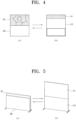
- FIG. 4 is a diagram illustrating an exterior of a TV according to another embodiment of the present disclosure.
- the TV may not necessarily include a material for a flexible display, and a screen of a general TV may be used without change in the embodiment of FIG. 4 .
- covers 400 having the same size or similar sizes may be positioned under the screen 401 of the TV.
- a cover 410 may be designed to move in an up direction to expose only a partial TV screen 411.
- a mode in (a) of FIG. 4 may be switched to a mode shown in (a) of FIG. 4 .
- a motor may be designed to be positioned around the cover.
- the TV designed as shown in FIG. 4 may be defined as an UNE TV
- a mode illustrated in (a) of FIG. 4 may be defined as a full view
- a mode illustrated in (b) of FIG. 4 may be defined as a line view or a partial view.
- FIG. 5 is a diagram illustrating an exterior of a TV according to further embodiment of the present disclosure.
- a material for a flexible display may not necessarily be used as a TV screen, and a general display may be used without change.
- the TV screen other than a cover itself is moved.
- the cover 500 having the same size or similar sizes is designed to be positioned under the TV screen 501.
- the TV screen 501 and the cover 500 may be apart from each other at a certain interval to prevent friction from being generated.
- a certain condition for example, when a signal pressing a power button of the remote controller once is input
- the TV screen 511 may move in an up direction to design the entire TV screen 511 to be exposed.
- a cover 510 may not move.
- a mode of (b) of FIG. 5 may be switched to a mode of (a) of FIG. 5 .
- a motor may be designed around the TV screen
- a TV designed as shown in FIG. 5 may be defined as an interior TV
- a mode illustrated in (a) of FIG. 5 may be defined as a partial view or a line view
- a mode illustrated in (b) of FIG. 5 may be defined as a full view.
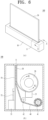
- FIG. 6 is a diagram for explaining a motor for adjusting a screen size of a TV according to an embodiment of the present disclosure.
- FIG. 6 illustrates a screen of the housing and the TV screen shown in FIG. 3 in a diagonal direction
- (b) of FIG. 6 is a cross-sectional view taken along a line A-A' of (a) of FIG. 6 .
- the TV system 100 may further include the housing 10.
- the housing 10 may be configured to accommodate various components, and more particularly, the housing 10 may accommodate, for example, the screen 30 and various electronic components for operating the screen 30.
- the TV system 100 may include the roller 20 rotatably installed in the housing 10.
- the roller 20 may include sleeves formed at both ends, and the sleeves may be rotatably supported with respect to the housing 10 by bearings.
- the roller 20 may be connected to the motor 21 installed in the housing 10, and may rotate in a clockwise direction R1 or a counterclockwise direction R2 as illustrated by the motor 21.
- a gear train may be located between the motor 21 and the roller 20.
- the TV system 100 may include the screen 30 configured to display various contents and information related to the contents.
- the screen 30 may display video content, audio content, and other ancillary content.
- Such contents include various pieces of information associated thereto, for example, a playback time in a video content, a title of the content, and the like, and the display 30 may also display such relevant information.
- the screen 30 may be accommodated in the housing 10 as illustrated in such a manner that the TV system 100 may have a compact structure. To accommodate the screen 30 in the housing 10, the screen 30 needs to be basically deformed. Accordingly, the TV system 100 may use a flexible display as the screen 30.
- the screen 30 may be rolled on the roller 20.
- the screen 30 may be wound around the roller 20 or unwound from the roller 20 according to a rotation direction of the roller 20.
- the screen 30 may be unwound from the roller 20 and project or roll out to the outside of the housing 10.
- the screen 30 may be wound around the roller 20 to retract/roll in the housing 10.
- the screen 30 when the roller 20 rotates in a clockwise direction R1, the screen 30 may be unwound from the roller 20 and be expanded to the outside of the housing 10 through an opening 11 formed in the housing 10.
- a screen accommodated in the housing 300 in (a) of FIG. 3 may be extended to the outside of the housing 310 as shown in (b) of FIG. 3 , and a screen 311 having a certain size may be formed.
- the screen 30 may be further unwound from the roller 20. Therefore, as shown in (c) of FIG. 3 , the screen may protrude to a larger size outside the housing 10, and may form a screen of a larger size.
- the screen 30 When the roller 20 rotates in the counterclockwise direction R1, the screen 30 may be wound around the roller 20 and may be contracted into the housing 10 through the opening 11. Accordingly, as shown in (b) of FIG.
- the screen 321 of (c) of FIG. 3 may be contracted to have a relatively smaller size inside the housing 310, thereby forming a smaller screen.
- the screen 30 may be further wound around the roller 20. Therefore, as shown in (a) of FIG. 3 , the screen may not protrude to the outside of the housing 300, and may be completely accommodated in the housing 300.
- a front portion of the screen 30, which is expanded from the TV system 100, may be protected by the window, while a rear portion of the screen 30 may be exposed.
- the screen 30 includes sensitive electronic components and substrates, and thus the screen 30 needs to be properly protected to prevent malfunction. Accordingly, as illustrated in (b) of FIG. 6 , the TV system 100 may include the cover 40 configured to cover the rear portion of the extended screen 30.
- the cover 40 may include a plurality of links connected to each other.
- the link may have a width corresponding to a width of the screen 30, and the links connected to each other, that is, the cover 40, may form a single plate covering the rear portion of the screen 30. Any one of the links is pivotable with respect to another adjacent link, and thus as shown in the drawing, the cover 40 may be wound around a first roller 41 and may be guided to a rear side of the screen 30 by the second roller 42.
- the first roller 41 may rotate to unwind the cover 40.
- the unwound cover 40 is guided by the second roller 41 and is attached to the rear portion of the screen 30. Accordingly, the cover 40 may be extended to the outside of the housing 10 together with the screen 30 to protect the rear portion of the screen 30.
- the first roller 41 When the screen 30 is contracted, the first roller 41 may rotate in an opposite direction to separate the cover 40 from the screen 30, and the separated cover 40 may be guided by the second roller 42 to be wound around the first roller 41.
- the first roller 41 In the cover 40, the first roller 41 may be driven by the motor 21 together with the roller 20, and a separate motor for driving the first roller 41 may be installed in the housing 10.
- the screen 30 may be difficult to maintain an expanded state due to the flexibility thereof.
- the TV system 100 may include the supporter 50 configured to support the extended screen 30.
- the supporter 50 may be extended to the outside of the housing 10 through the opening 11 by the motor 51 and the auxiliary supporter 52 connected thereto. Accordingly, the supporter 50 may be extended to the outside of the housing 10 together with the screen 30. Accordingly, the screen 30 expanded by the supporter 50 may be stably supported to display content to the user.
- an OLED display may be used as a screen used in FIGs. 1 to 6 .
- the OLED display has many advantages such as a free form factor, infinite contrast ratio, spontaneous light emission, color representation close to natural color, and the like.
- the OLED display has a TFT switch under an organic material to turn on/off a device.
- a voltage is applied to the TFT switch to turn on/off, and intensity of light is adjusted by controlling an amount of a current.
- the following TV form factor is exemplarily described with reference to FIG. 5 , but the present disclosure may be applied to all TV products having a variable size of an exposed screen.
- FIG. 7 is a block diagram illustrating components of a TV according to an embodiment of the present disclosure.
- a TV 700 includes a sensor 710, a display 720, a memory 730, a controller 740, a motor 750, etc.
- a sensor 710 a sensor 710
- a display 720 a display 720
- a memory 730 a controller 740
- a motor 750 a motor 750
- the sensor 710 is designed to detect whether at least one user exists around the TV 700.
- the sensor 710 may include, for example, a camera, an IR infrared sensor, etc.
- the display 720 displays the video in color.
- the first view mode includes, for example, a case that only a screen is exposed partially and correspond, for example, to the state (a) of FIG. 5 .
- the controller 740 reduces brightness of the video and controls the video to be displayed in black and white again.
- the motor 750 adjusts the screen to switch from the first view mode to a second view mode (described in more detail later with reference to FIG. 11 ). Meanwhile, the driving of the motor is described in more detail with reference to FIG. 6 , and thus a redundant description will be omitted.
- the second view mode includes, for example, a case where the screen is fully exposed, and corresponds to, for example, the state (b) of FIG. 5 .
- the controller 740 additionally controls the motor 750 to adjust an exposed size of the screen, and adjusts the position of the video displayed on the screen. Regarding this, a more specific embodiment will be described in detail with reference to FIG. 14 .
- the controller 740 is designed to separately count a use time in the first view mode and a use time in the second view mode.
- a reference time for performing afterimage compensation in the first view mode is designed to be shorter than a reference time for performing afterimage compensation in the second view mode.
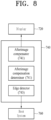
- FIG. 8 is a block diagram illustrating the controller shown in FIG. 7 in more detail.
- the display 720 is configured to display a video and includes a display panel having pixels to display the video image, a data driver for driving a data line, and a gate driver for driving a gate line.
- the display 720 may include, for example, an Organic Light Emitting Diodes (OLED) display.
- OLED Organic Light Emitting Diodes
- the controller 740 receives various control signals such as power, image data, a timing signal, and the like from a host system 760, which will be described later, and controls an operation of the display 720 based on the received control signals.
- the controller 740 captures an image inputted from the host system 760 to detect an edge, determines an afterimage compensation target pixel based on edge strength, brightness, edge accumulation count value, and the like for each pixel, and performs afterimage compensation on the afterimage compensation target pixel.
- the controller 740 may include a memory storing an edge detection algorithm, an algorithm for detecting an afterimage area, a data table, a control algorithm, and a control code therein and a processor for executing the algorithms.
- the controller 740 may be provided in a timing controller.
- the controller 740 includes an edge detector 743, an afterimage compensation determiner 742, and an afterimage compensator 741.
- the edge detector 743 captures an input image frame at a predetermined period and detects an edge area from the captured image frame.
- the image capture and edge detection period may be determined to be between 15 seconds and 45 seconds.
- the image capture and edge detection period may be set shorter (e.g. 20 seconds or less) in the first view mode, and the image capture and edge detection period may be set longer (e.g. 30 seconds or more) in the second view mode. This is a designed to consider that a burn-in phenomenon is more likely to occur in the first view mode.
- the edge detector 743 detects an edge area when a brightness change value between pixels for each area of the image frame is equal to or greater than a reference value.
- the edge detector 743 may be implemented as any one of various algorithms to which a method of using a mask having a fixed value, such as Roberts, Sobel, Prewitt, and Laplacian, a morphology method for accessing and processing an image in morphological aspect, a method for detecting a Canny edge, and the like are applied. For example, when there is a brightness difference between a pixel and a peripheral pixel ranges between 35% ⁇ 45% or more, it may be detected as an edge area..
- a memory (not shown) in which a data table related to the edge area is stored is provided, and the data table related to the edge area stores an edge strength, an image brightness (e.g. WRGB brightness), and an edge accumulation count value for each pixel coordinates.
- an image brightness e.g. WRGB brightness
- an edge accumulation count value for each pixel coordinates.
- the edge detector 743 saves result values, for example, the edge strength, the image brightness, and the edge accumulation count value in the data table related to the edge area based on the result of the edge area detection.
- the edge strength and the image brightness mean the accumulated average value
- the edge accumulation count value refers to the number of times accumulated as the edge. If the corresponding pixel is not consecutively detected as the edge area, the corresponding edge accumulation count value is reset.
- the afterimage compensation determiner 742 detects a pixel, which has been detected as an edge area consecutively by a predetermined count value or more by the edge detector 743, as an afterimage compensation area, and determines a pixel, of which accumulation count value detected as the afterimage compensation area is equal to or greater than a predetermined threshold value, as an afterimage compensation target pixel.
- a memory (not shown) in which a data table related to the afterimage compensation area is stored is provided, and the data table related to the afterimage compensation area stores edge strength, image brightness (e.g. WRGB brightness), and afterimage compensation area accumulation count value for each pixel.
- the afterimage compensation detector 742 may detect the pixel as an afterimage compensation area and update the edge strength, the image brightness (e.g. WRGB brightness), and the afterimage compensation area accumulation count value on coordinates of the corresponding pixel in the data table related to the afterimage compensation area.
- a first threshold e.g., n times in the edge area related data table
- the afterimage compensation determiner 742 detects a corresponding pixel as an afterimage compensation area, turns on an afterimage compensation area flag, and updates an afterimage compensation area value related to the corresponding pixel coordinates in the data table related to the afterimage compensation area.
- the afterimage compensation determiner 742 stores an accumulated average value of the edge strength and the image brightness of the corresponding pixel in the data table related to the afterimage compensation area, and stores the afterimage area accumulation count value by accumulating the afterimage area counting number. For example, when the accumulation count value of a pixel at the coordinates (200, 199( is counted to 20, the afterimage compensation determiner 742 accumulates 1 in the afterimage compensation accumulation count value of the coordinates (200, 199) in the data table of the afterimage compensation area and resets the edge accumulation count value of the data table about the edge area.
- the afterimage compensation determiner 742 determines a pixel, of which afterimage area accumulation count value is equal to or greater than a second threshold, e.g., m times or more, as an afterimage compensation target pixel,.
- a second threshold e.g., m times or more
- 'm' may be determined in consideration of an afterimage characteristic and the like of the display 720 .
- a weight is given to a time T1 used in the first view mode, and thus it is designed to determine an afterimage compensation ahead of a time T2 used in the second view mode.
- the afterimage compensator 741 performs afterimage compensation on the pixel, of which afterimage compensation enable flag is turned on, as determined as the afterimage compensation target pixel by afterimage compensation determiner 742.
- the afterimage compensator 741 When a power of the TV is turned off, the afterimage compensator 741 performs afterimage compensation on the pixel of which afterimage compensation enable flag is turned on.
- an afterimage compensation algorithm may operate in response to a user request, and may be designed so that an afterimage compensation algorithm is applied to all pixels other than a specific pixel, which comes within the scope of rights of the present disclosure.
- FIG. 9 is a flowchart illustrating a method of controlling a TV according to an embodiment of the present disclosure.
- a TV according to an embodiment of the present disclosure is designed to display a video in black and white in a first view mode (S 910).
- a sensor e.g. a camera, an IR sensor, etc.
- the TV displays the video in color (S 930). Therefore, there is an advantage in that not only a function of communicating with a user can be provided, but also an afterimage or burn-in problem of a screen may be blocked in advance.
- the senor determines again whether the at least one user is detected again (S 940).
- the motor is controlled to be switched from the first view mode to a second view mode (S 960). For example, if the user is detected for 15 seconds or more, it is estimated that the user has an intention to use a content as a full screen.
- FIG. 10 illustrates an example of performing afterimage removal by a TV depending on whether a user is present according to an embodiment of the present disclosure.
- a TV 1000 exposes only a portion of a screen 1010 in a first view mode. In doing so, the TV 100 displays a video on the screen 1010 in black and white so as to minimize an afterimage problem.
- the TV 10010 changes the video displayed on the screen 1011 to a color video. Accordingly, there is a technical effect of minimizing the afterimage problem and the burn-in phenomenon while minimizing a change in a current screen (i.e., maintaining the same video content).
- FIG. 11 illustrates another example of performing afterimage removal by a TV depending on a presence or non-presence of a user according to an embodiment of the present disclosure.
- a TV 1100 As shown in FIG. 11 ( a ), a TV 1100 according to an embodiment of the present disclosure exposes only a portion of a screen 1110 in a first view mode. In doing so, in order to minimize the afterimage problem, the TV 1100 displays a video in black and white on the screen 1110.
- the TV 1101 exposes the screen 1111 to the maximum value while switching to a second view mode.
- a user sensing time of being triggered from (a) to (b) of FIG. 10 is designed to a case of satisfying, for example, T1(2-3) seconds
- a user sensing time of being triggered from (a) to ( b ) of FIG. 11 is designed to a case of satisfying, for example, T2 (5-6) seconds. That is, T2 is designed to be larger than T1, but the scope of rights of the present disclosure is not limited to the illustrated numerical values.
- FIG. 12 illustrates another example of performing afterimage removal by a TV depending on a presence or non-presence of a user according to an embodiment of the present disclosure. Unlike FIG. 11 , FIG. 12 illustrates s a technique for a solution for performing afterimage removal without switching a view mode.
- a TV according to an embodiment of the present disclosure exposes only a portion of a screen 1200 in a first view mode. In doing so, in order to minimize the afterimage problem, the TV displays a video in black and white on the screen 1200.
- the TV displays the same video in color on the screen 1210 while maintaining the first view mode.
- the TV displays the same video on the screen 1220 and gradually lowers a brightness level.
- FIGs. 10 to 12 illustrate the methods of resolving the burn-in phenomenon by switching a black-and-white/color format while outputting the same video.
- FIG. 13 illustrates an example of a process of operating a screen saver provided by a TV according to an embodiment of the present disclosure.
- a video in color is displayed.
- a first view mode that is, in a state that only a portion of a screen 1300 is exposed.
- a video in color is displayed.
- an item 1311 operating as a screen saver is displayed on the screen 1310 of the TV.
- the item indicating time is illustrated in the drawing, the scope of rights of the present disclosure is not necessarily limited thereto.
- the item 1321 is controlled to be displayed at another location within the screen 1320 of the TV. That is, during the screen saver operation, the item 1321 randomly moves and, although not shown in the drawing, a size or color thereof may be changed.
- the TV When the TV receives a remote controller input, the TV returns to the screen 1300 of FIG. 13 ( a ) and the previous item 1311/1321 disappears. In this case, it is designed in consideration of a fact that possibility of continuing to display the same video on the screen is lowered through a signal inputted by a user through the remote controller.
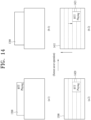
- FIG. 14 illustrates another example of an operation process of a screen saver provided by a TV according to an embodiment of the present disclosure.
- FIG. 14 shows an advantage in that there is no need to generate a separate item.
- a screen is movable.
- FIG. 14 ( a -1) it is assumed that only a portion of a screen 1400 is exposed in a first view mode. Even when a music file is being played in the first view mode, relevant music information is displayed within the screen 1400. In particular, unlike a second view mode, since there is a high possibility of a video change in the first view mode, a solution for solving this problem is necessarily required.
- FIG. 14 ( a -2) is an enlarged view of the screen 1400 shown in FIG. 14 ( a -1).
- information 1420 related to a currently played music is displayed at a specific location on a screen 1410 of a TV according to an embodiment of the present disclosure.
- the TV is designed to enable a screen saver to be automatically operated. For example, when the remote controller command is not received for 30 minutes to 1 hour in the first view mode, the screen saver is automatically operated.
- the screen 1401 of the TV is slightly further exposed in an up-direction. Only the screen 1401 shown in FIG. 14 ( b -1) is enlarged and illustrated in FIG. 14 ( b -2).
- the screen 1411 moves in the up-direction to have a larger exposed size.
- the music-related information 1421 is designed to move in a down-direction within the screen 1411.
- the moving distances are designed to be the same, and thus it is recognized that the information 1421 is displayed at the same position in the viewpoint of a user. Furthermore, according to this design, the actual position at which the information 1421 is displayed is slightly changed, thereby being advantageous in solving the afterimage problem.
- the present disclosure may be embodied as a computer-readable code on a medium in which a program is recorded.
- the computer-readable medium includes all kinds of recording devices for storing data that can be read by a computer system. Examples of the computer readable medium include Hard Disk Drive (HDD), Solid State Disk (SSD), Silicon Disk Drive (SDD), ROM, RAM, CD- ROM, magnetic tape, floppy disk, optical data storage device, and the like and may also be implemented in the form of carrier waves (e.g. transmission over the Internet).
- the computer may also include a controller. Accordingly, the foregoing detailed description should not be construed as being limited in all respects and should be considered to be illustrative. The scope of the present disclosure should be determined by the reasonable interpretation of the appended claims, and all changes within the equivalent scope of the present disclosure are included in the scope of the present disclosure.
- the present disclosure is applicable to TVs of various form factors such as a rollable TV and the like, and thus is industrially applicable.
Landscapes
- Engineering & Computer Science (AREA)
- Theoretical Computer Science (AREA)
- Multimedia (AREA)
- Signal Processing (AREA)
- General Engineering & Computer Science (AREA)
- Physics & Mathematics (AREA)
- General Physics & Mathematics (AREA)
- Computer Hardware Design (AREA)
- Health & Medical Sciences (AREA)
- Human Computer Interaction (AREA)
- Databases & Information Systems (AREA)
- Social Psychology (AREA)
- General Health & Medical Sciences (AREA)
- Life Sciences & Earth Sciences (AREA)
- Ecology (AREA)
- Emergency Management (AREA)
- Environmental & Geological Engineering (AREA)
- Environmental Sciences (AREA)
- Remote Sensing (AREA)
- Biodiversity & Conservation Biology (AREA)
- Business, Economics & Management (AREA)
- Computer Security & Cryptography (AREA)
- Computer Networks & Wireless Communication (AREA)
- Devices For Indicating Variable Information By Combining Individual Elements (AREA)
Applications Claiming Priority (1)
| Application Number | Priority Date | Filing Date | Title |
|---|---|---|---|
| PCT/KR2022/000071 WO2023132376A1 (ko) | 2022-01-04 | 2022-01-04 | Tv 및 그 제어 방법 |
Publications (2)
| Publication Number | Publication Date |
|---|---|
| EP4456541A1 true EP4456541A1 (de) | 2024-10-30 |
| EP4456541A4 EP4456541A4 (de) | 2025-02-12 |
Family
ID=87073767
Family Applications (1)
| Application Number | Title | Priority Date | Filing Date |
|---|---|---|---|
| EP22918913.9A Pending EP4456541A4 (de) | 2022-01-04 | 2022-01-04 | Fernseher und steuerungsverfahren dafür |
Country Status (2)
| Country | Link |
|---|---|
| EP (1) | EP4456541A4 (de) |
| WO (1) | WO2023132376A1 (de) |
Family Cites Families (8)
| Publication number | Priority date | Publication date | Assignee | Title |
|---|---|---|---|---|
| JP4851720B2 (ja) * | 2005-02-24 | 2012-01-11 | Necディスプレイソリューションズ株式会社 | 表示装置及びこれを用いた大型表示装置 |
| KR102244620B1 (ko) * | 2014-09-05 | 2021-04-26 | 삼성전자 주식회사 | 렌더링 수준 제어 방법 및 장치 |
| KR102330164B1 (ko) * | 2017-06-08 | 2021-11-24 | 엘지전자 주식회사 | 디지털 사이니지 및 그 동작 방법 |
| CN113614676B (zh) * | 2019-05-20 | 2024-03-26 | 谷歌有限责任公司 | 用于提供多模式界面的基于移动设备的雷达系统及其方法 |
| KR102737483B1 (ko) * | 2019-08-16 | 2024-12-02 | 엘지전자 주식회사 | 영상표시장치 및 이의 제어방법 |
| KR102950349B1 (ko) * | 2019-12-03 | 2026-04-10 | 엘지전자 주식회사 | 디스플레이 장치 |
| KR102725331B1 (ko) * | 2019-12-30 | 2024-11-01 | 엘지디스플레이 주식회사 | 디스플레이 장치 및 그의 영상 처리 방법 |
| KR102720350B1 (ko) * | 2020-05-22 | 2024-10-23 | 엘지디스플레이 주식회사 | 게이트 구동회로 및 이를 이용한 표시장치 |
-
2022
- 2022-01-04 WO PCT/KR2022/000071 patent/WO2023132376A1/ko not_active Ceased
- 2022-01-04 EP EP22918913.9A patent/EP4456541A4/de active Pending
Also Published As
| Publication number | Publication date |
|---|---|
| EP4456541A4 (de) | 2025-02-12 |
| WO2023132376A1 (ko) | 2023-07-13 |
Similar Documents
| Publication | Publication Date | Title |
|---|---|---|
| CN105247853B (zh) | 具有柔性显示器的多媒体装置及其控制方法 | |
| JP5783245B2 (ja) | カスタマイズされたフォーマットに従ってビデオストリームを表示する方法 | |
| CN106251800B (zh) | 用于增强可见度的显示系统及其方法 | |
| CN102640081B (zh) | 通过检测用户的存在的姿势识别设备的功率控制方法 | |
| KR20160116576A (ko) | 디스플레이장치 및 그 제어방법 | |
| US20180165052A1 (en) | Display apparatus and method of controlling the same | |
| JP2007300270A5 (de) | ||
| US12563254B2 (en) | TV and control method therefor | |
| EP4456541A1 (de) | Fernseher und steuerungsverfahren dafür | |
| US20250392780A1 (en) | Wireless transmitting device and wireless display system | |
| JP3819870B2 (ja) | 画像表示装置 | |
| US11270612B2 (en) | Image display apparatus | |
| US12556647B2 (en) | TV and control method thereof | |
| KR101315298B1 (ko) | 카메라로 촬영된 영상에서의 osd 표시 제어방법 및 장치, 모니터에서의 osd 표시 제어방법 및 장치 | |
| KR102714427B1 (ko) | 디스플레이장치, 그 제어방법 및 기록매체 | |
| US12477182B2 (en) | TV and method for controlling same | |
| US20250046222A1 (en) | Display device and control method therefor | |
| KR102955570B1 (ko) | 디스플레이 디바이스 및 그 제어 방법 | |
| KR20020059545A (ko) | 티브이의 영상표시 제어방법 | |
| EP4429227A1 (de) | Fernseher und steuerungsverfahren dafür | |
| KR102658129B1 (ko) | 영상표시장치 | |
| US12360728B2 (en) | Display device and control method therefor | |
| JP2007336313A (ja) | 映像表示装置、映像表示方法、プログラム | |
| KR20240110008A (ko) | 디스플레이 디바이스 및 그 제어 방법 | |
| KR20240090205A (ko) | 디스플레이 디바이스 및 그 제어 방법 |
Legal Events
| Date | Code | Title | Description |
|---|---|---|---|
| STAA | Information on the status of an ep patent application or granted ep patent |
Free format text: STATUS: THE INTERNATIONAL PUBLICATION HAS BEEN MADE |
|
| PUAI | Public reference made under article 153(3) epc to a published international application that has entered the european phase |
Free format text: ORIGINAL CODE: 0009012 |
|
| STAA | Information on the status of an ep patent application or granted ep patent |
Free format text: STATUS: REQUEST FOR EXAMINATION WAS MADE |
|
| 17P | Request for examination filed |
Effective date: 20240726 |
|
| AK | Designated contracting states |
Kind code of ref document: A1 Designated state(s): AL AT BE BG CH CY CZ DE DK EE ES FI FR GB GR HR HU IE IS IT LI LT LU LV MC MK MT NL NO PL PT RO RS SE SI SK SM TR |
|
| A4 | Supplementary search report drawn up and despatched |
Effective date: 20250113 |
|
| RIC1 | Information provided on ipc code assigned before grant |
Ipc: H04N 21/8549 20110101ALI20250107BHEP Ipc: G09F 9/00 20060101ALI20250107BHEP Ipc: G06F 1/16 20060101ALI20250107BHEP Ipc: G02F 1/133 20060101ALI20250107BHEP Ipc: G06V 40/16 20220101ALI20250107BHEP Ipc: H04N 5/21 20060101ALI20250107BHEP Ipc: H04N 9/43 20060101ALI20250107BHEP Ipc: H04N 21/4223 20110101ALI20250107BHEP Ipc: H04N 21/422 20110101ALI20250107BHEP Ipc: H04N 21/466 20110101ALI20250107BHEP Ipc: H04N 21/462 20110101ALI20250107BHEP Ipc: H04N 21/485 20110101AFI20250107BHEP |
|
| DAV | Request for validation of the european patent (deleted) | ||
| DAX | Request for extension of the european patent (deleted) | ||
| STAA | Information on the status of an ep patent application or granted ep patent |
Free format text: STATUS: EXAMINATION IS IN PROGRESS |
|
| 17Q | First examination report despatched |
Effective date: 20251202 |