EP4424481A2 - Appareil de coupe permettant de découper des tubes ou des manchons - Google Patents
Appareil de coupe permettant de découper des tubes ou des manchons Download PDFInfo
- Publication number
- EP4424481A2 EP4424481A2 EP24189624.0A EP24189624A EP4424481A2 EP 4424481 A2 EP4424481 A2 EP 4424481A2 EP 24189624 A EP24189624 A EP 24189624A EP 4424481 A2 EP4424481 A2 EP 4424481A2
- Authority
- EP
- European Patent Office
- Prior art keywords
- shell
- cutting
- shell part
- cutting device
- receptacle
- Prior art date
- Legal status (The legal status is an assumption and is not a legal conclusion. Google has not performed a legal analysis and makes no representation as to the accuracy of the status listed.)
- Pending
Links
Images


Classifications
-
- B—PERFORMING OPERATIONS; TRANSPORTING
- B23—MACHINE TOOLS; METAL-WORKING NOT OTHERWISE PROVIDED FOR
- B23D—PLANING; SLOTTING; SHEARING; BROACHING; SAWING; FILING; SCRAPING; LIKE OPERATIONS FOR WORKING METAL BY REMOVING MATERIAL, NOT OTHERWISE PROVIDED FOR
- B23D79/00—Methods, machines, or devices not covered elsewhere, for working metal by removal of material
-
- B—PERFORMING OPERATIONS; TRANSPORTING
- B26—HAND CUTTING TOOLS; CUTTING; SEVERING
- B26D—CUTTING; DETAILS COMMON TO MACHINES FOR PERFORATING, PUNCHING, CUTTING-OUT, STAMPING-OUT OR SEVERING
- B26D3/00—Cutting work characterised by the nature of the cut made; Apparatus therefor
- B26D3/16—Cutting rods or tubes transversely
- B26D3/169—Hand held tube cutters
-
- B—PERFORMING OPERATIONS; TRANSPORTING
- B23—MACHINE TOOLS; METAL-WORKING NOT OTHERWISE PROVIDED FOR
- B23D—PLANING; SLOTTING; SHEARING; BROACHING; SAWING; FILING; SCRAPING; LIKE OPERATIONS FOR WORKING METAL BY REMOVING MATERIAL, NOT OTHERWISE PROVIDED FOR
- B23D21/00—Machines or devices for shearing or cutting tubes
- B23D21/06—Hand-operated tube-cutters
- B23D21/10—Hand-operated tube-cutters with other cutting blades or tools
-
- B—PERFORMING OPERATIONS; TRANSPORTING
- B23—MACHINE TOOLS; METAL-WORKING NOT OTHERWISE PROVIDED FOR
- B23Q—DETAILS, COMPONENTS, OR ACCESSORIES FOR MACHINE TOOLS, e.g. ARRANGEMENTS FOR COPYING OR CONTROLLING; MACHINE TOOLS IN GENERAL CHARACTERISED BY THE CONSTRUCTION OF PARTICULAR DETAILS OR COMPONENTS; COMBINATIONS OR ASSOCIATIONS OF METAL-WORKING MACHINES, NOT DIRECTED TO A PARTICULAR RESULT
- B23Q11/00—Accessories fitted to machine tools for keeping tools or parts of the machine in good working condition or for cooling work; Safety devices specially combined with or arranged in, or specially adapted for use in connection with, machine tools
- B23Q11/08—Protective coverings for parts of machine tools; Splash guards
-
- B—PERFORMING OPERATIONS; TRANSPORTING
- B23—MACHINE TOOLS; METAL-WORKING NOT OTHERWISE PROVIDED FOR
- B23Q—DETAILS, COMPONENTS, OR ACCESSORIES FOR MACHINE TOOLS, e.g. ARRANGEMENTS FOR COPYING OR CONTROLLING; MACHINE TOOLS IN GENERAL CHARACTERISED BY THE CONSTRUCTION OF PARTICULAR DETAILS OR COMPONENTS; COMBINATIONS OR ASSOCIATIONS OF METAL-WORKING MACHINES, NOT DIRECTED TO A PARTICULAR RESULT
- B23Q3/00—Devices holding, supporting, or positioning work or tools, of a kind normally removable from the machine
-
- B—PERFORMING OPERATIONS; TRANSPORTING
- B26—HAND CUTTING TOOLS; CUTTING; SEVERING
- B26D—CUTTING; DETAILS COMMON TO MACHINES FOR PERFORATING, PUNCHING, CUTTING-OUT, STAMPING-OUT OR SEVERING
- B26D5/00—Arrangements for operating and controlling machines or devices for cutting, cutting-out, stamping-out, punching, perforating, or severing by means other than cutting
- B26D5/08—Means for actuating the cutting member to effect the cut
- B26D5/10—Hand or foot actuated means
-
- B—PERFORMING OPERATIONS; TRANSPORTING
- B26—HAND CUTTING TOOLS; CUTTING; SEVERING
- B26D—CUTTING; DETAILS COMMON TO MACHINES FOR PERFORATING, PUNCHING, CUTTING-OUT, STAMPING-OUT OR SEVERING
- B26D7/00—Details of apparatus for cutting, cutting-out, stamping-out, punching, perforating, or severing by means other than cutting
- B26D7/26—Means for mounting or adjusting the cutting member; Means for adjusting the stroke of the cutting member
- B26D7/2614—Means for mounting the cutting member
-
- B—PERFORMING OPERATIONS; TRANSPORTING
- B23—MACHINE TOOLS; METAL-WORKING NOT OTHERWISE PROVIDED FOR
- B23D—PLANING; SLOTTING; SHEARING; BROACHING; SAWING; FILING; SCRAPING; LIKE OPERATIONS FOR WORKING METAL BY REMOVING MATERIAL, NOT OTHERWISE PROVIDED FOR
- B23D35/00—Tools for shearing machines or shearing devices; Holders or chucks for shearing tools
- B23D35/002—Means for mounting the cutting members
Definitions
- the invention relates to a cutting device for cutting pipes or sleeves to length, with a cutting mouth consisting of two shell parts, each with a shell receptacle, wherein the shell parts can be pivoted relative to one another about a pivot axis, wherein a cutting blade is arranged in at least one shell part.
- the invention also relates to a cutting device for cutting pipes or sleeves to length, with a cutting mouth consisting of two shell parts, a first and a second shell part, each with a shell receptacle, wherein the shell parts can be pivoted relative to one another about a pivot axis, wherein a cutting blade is arranged in at least one shell part.
- the invention also relates to a cutting device for cutting pipes or sleeves to length, with a cutting mouth consisting of two shell parts, a first and a second shell part, each with a shell receptacle, wherein the shell parts can be pivoted relative to one another about a pivot axis.
- Cutting devices of the type in question are known, in particular for cutting pipes, and in particular plastic pipes.
- Such pipes, in particular plastic pipes can be used in the sanitary sector as water inlet and/or water outlet pipes, for example, and can also be used in electrical installations, in particular for the protective accommodation of one or more cables.
- High-temperature sewage pipes or electrical conduits can also be cut using such cutting devices.
- Such cutting devices are also known, by means of which sleeves, for example so-called drip sleeves, can be cut to length.
- Known designs of such cutting devices preferably have two shell parts that are connected to one another in an articulated manner and can be pivoted relative to one another about a pivot axis that is aligned in the longitudinal direction of the cutting device as a whole from an open position to a working position and back.
- a knife carrier of the cutting knife is formed integrally with a shell part.
- the blade can be removed from the cutting device together with the blade carrier, for example to replace the cutting blade alone or together with the blade carrier when it is worn out.
- the cutting blade alone or together with the For example, the knife carrier can be replaced with an alternative cutting knife for certain applications.
- the positioning of the cutting knife within the cutting device, in particular within the shell part carrying the cutting knife with the knife carrier, can also be changed.
- the cutting blade is detachably held on the blade carrier.
- the connection in this case can be removed or made using a conventional tool, as is also preferred.
- a screw fastening is preferred in this respect.
- the blade carrier is arranged in the shell part in a reversible manner.
- the blade carrier can also have a longitudinal extension that is directed essentially in the direction of extension of the pivot axis.
- the blade carrier can also preferably be turned essentially about a body axis that runs perpendicular to the geometric pivot axis, so that one end of the blade carrier, after turning, preferably points 180 degrees in the opposite direction to before.
- a change in the positioning of the cutting knife can be achieved and/or a change in the cutting edge of the cutting knife that is effective during the cutting process.
- a straight effective cutting edge can be exchanged for a concave or convex effective cutting edge.
- the cutting depth of the cutting knife can be changed by turning the knife holder.
- the cutting knife can be arranged essentially centrally in an orientation of the knife carrier with respect to the longitudinal extension of the cutting device, in particular with respect to the longitudinal extension of the shell part carrying the knife carrier.
- the positioning of the cutting knife can be changed in such a way that the cutting knife is arranged off-center with respect to the longitudinal extension of the cutting device.
- the cutting knife can be positioned, for example, close to the edge of the shell part holding the knife carrier, for example to use the cutting device to cut so-called drip sleeves to length.
- the knife carrier can be arranged in the shell part so that it can move in the direction of the pivot axis, according to one possible embodiment.
- a displaceability can arise within the shell part, if necessary, as is also preferred, after removing a design that fixes the knife carrier in the shell part.
- a guide that enables the sliding displaceability can also be provided, for example in the form of a rail-like guide.
- several guide receptacles can be provided for the knife carrier, which can (also) enable the knife carrier to be arranged at different heights in the shell part. Accordingly, depending on the arrangement of the knife carrier in one or the other guide receptacle different projection positions of the cutting edge beyond the surface of the cutting holder in the direction of the cutting mouth result.
- two guide holders are preferably provided for the different arrangement of the knife carrier at two different heights. More than two, for example three or four, such guide holders can also be formed in the shell part.
- the knife carrier can be fixed in the shell part, for example, using a screw. Using such a screw, for example, the knife carrier can preferably be fixed in the shell part in both turning positions.
- the guide mounts also preferably act to prevent rotation.
- a receptacle for the screw in the knife carrier, as well as the receptacle in the shell part that interacts with the screw, preferably extends transversely to a displacement direction of the knife carrier.
- the displacement direction is further preferably aligned in the same direction as the direction of extension of the pivot axis.
- the opening angle ⁇ of the V-shell receptacle is between 80 and 100°.
- the advantageous opening angle of the V-legs of the V-shell holder offers favorable circumferential support of the pipe or sleeve to be cut over a comparatively large diameter range, whereby a centered alignment of the workpiece to be cut can be achieved at the same time by the V-shaped positioning of the holder edges.
- an opening angle of between about 85 and about 95 degrees is preferred, more preferably about 90 degrees.
- radially outer ends of the shell parts can be movable on different radii, wherein a radially shorter first shell part can be moved until it overlaps the shell receptacle of the second shell part and, when the shell parts are completely retracted, the radially outer free end of the second shell part is free from overlap by the first shell part in a pivot direction.
- the cutting device proves to be compact in the working position, but also in a possible storage position. Due to the proposed geometry, one-handed operation of the cutting device during a cutting process is possible over a comparatively large diameter range of the pipe or sleeve to be cut, for example 10 mm up to 80 mm, and furthermore for example 20 mm up to 50 mm.
- the radially outer end of the shorter first shell part can move around the geometric pivot axis on a radius which can correspond, for example, to approximately 0.5 to 0.85 times, furthermore approximately 0.65 to 0.75 times the radius of the outer end of the second longer shell part.
- the radially shorter first shell part can move at least over a pivoting range, in particular over a pivoting range in which pipes or sleeves with a comparatively small diameter are cut or in which the shell parts can come into contact with one another. in particular in the region of the free end, they overlap at least partially in a radial direction with respect to the pivot axis to the second shell part, whereby a compact design of the cutting device can be achieved with an ergonomically favorable configuration.
- the overlap can, as is also preferred, be in a radial direction, particularly when viewed in one direction along the pivot axis.
- the shorter first shell part can accordingly be partially nested in the second shell part, at least in one pivot position. This results in a nesting, particularly in the fully retracted position of the shell parts, in which the free end of the longer second shell part, in the extension of the curvature of this second shell part, is not covered by the first shell part or sections of the first shell part. This particularly applies to an end face of the longer second shell part. An end face of the first shell part moves on radii that lie within radii of the end face of the second shell part.
- a surface of the second shell part forming the shell receptacle is penetrated by the radially outer end of the first shell part.
- the first shell part can penetrate the surface of the second shell part at the end, ie facing away from the pivot axis, with an end region, which end region can extend, for example, over approximately one eighth to one quarter, more preferably approximately one sixth of the extension length of the first shell part viewed transversely to the orientation of the pivot axis, starting from the pivot axis.
- such an implementation can optionally occur over a pivoting range of the first shell part relative to the second shell part of approximately 10 to 20 degrees, further approximately 15 degrees.
- the first shell part can preferably pivot, starting from a first contact with the surface of the shell receptacle of the second shell part, through a pivoting angle of, for example, approximately 15 degrees, preferably maintaining the overlap with the second shell part in the direction of the retracted position.
- the surface of the shell receptacle of the second shell part can be formed partly as a real surface and partly as an envelope surface.
- the imaginary envelope surface preferably results from a surface that connects the real surfaces in their surface extension.
- a circular and/or flat envelope surface results at least in sections.
- the envelope surface can also result between the real surfaces, particularly when viewed in the direction of extension of the pivot axis.
- the penetration is achieved in the area of the envelope surface.
- the penetration between the areas of the real surfaces of the shell receptacle is made possible, for example by a slot-shaped design of the shell receptacle or by forming openings to be penetrated.
- the end faces of ribs projecting inwards on the second shell part i.e. in the direction of the cutting mouth, can form a surface, and in particular the real surface.
- the shell parts have several have spaced rib formations that extend transversely to the pivot axis.
- the rib formations protruding in the radial direction leave, when viewed in the direction of the pivot axis, preferably groove-shaped depressions between them.
- Such a depression is further preferably ergonomically favorable in the form of a groove in which the finger can rest, preferably guided laterally on both sides by the rib formation.
- a shell part can have three or more, for example up to five, rib formations of this kind on the outside, which can preferably be evenly spaced from one another in the direction of the pivot axis. Accordingly, two, three or four throat-like depressions can also be formed, in which a corresponding number of fingers can be placed when the cutting device is used.
- Such rib formations and the resulting depressions can be provided on the outside of both shell parts for ease of handling and also preferably.
- a rib formation of one shell part continues in the other shell part with an interruption by the pivot axis.
- Such a continuation of the rib formations and thus also a resulting continuation of the, for example, throat-like finger formations beyond the connecting area of the two shell parts proves to be particularly advantageous in terms of handling and ergonomics.
- the cutting device is also When grasped with one hand, it can be securely gripped beyond the connection or swivel range.
- the shell holder of the further (first) shell part can be formed in the shape of a circular segment.
- the shell part is thus formed as a circular segment shape.
- a circular line shape with a constant radius or a composite circular line shape with different radii can result.
- this circular segment shape of the shell part arises in particular in the cutting plane resulting transversely to the pivot axis.
- This circular segment shape can be interrupted by the cutting blade protruding from the shell holder. Accordingly, in the area of the cutting mouth, at least a portion of the cutting blade projects beyond the shell holder, with this projecting area of the cutting blade preferably being formed at an angle.
- This projecting area is therefore an angular projecting area.
- a projecting area can thus result with two edges that are at an angle of preferably 75 to 115 degrees, more preferably about 90 degrees to one another, with at least one edge forming a cutting edge. At least one of these edges can be represented as an imaginary line connecting straight ends, for example of the cutting edge.
- the angled projection area of the cutting blade can be formed by a short leg and a long leg.
- the long leg can also be, as is preferred, a part of the It can be the cutting edge of the cutting blade or a section of the imaginary straight line described above.
- a V-leg of the shell receptacle of one (second) shell part can transition into a curve facing inwards towards the cutting mouth.
- each V-leg can (initially) run at least approximately straight in the plane transverse to the pivot axis, particularly starting from the V-tip, which is preferably rounded.
- the straight course of the V-leg which preferably faces away from the pivot axis, transitions into the curve described above in the direction of its radially outer free end. With this end-curved end region, the longer second shell part overlaps the first shell part at a radial distance, particularly when the shell parts are completely moved together.
- the above-described curvature of the V-leg can, as is also preferred, be formed essentially in the shape of a circular segment.
- the ranges or value ranges or multiple ranges specified above and below also include all intermediate values with regard to the disclosure, in particular in 1/10 steps of the respective dimension, and possibly also dimensionless.
- the specification 80 to 100° also includes the disclosure of 80.1 to 100 degrees, 80 to 99.9 degrees, 80.1 to 99.9 degrees, etc.
- the disclosure of 0.5 to 0.85 times also includes the disclosure of 0.6 to 0.85 times, 0.5 to 0.75 times, 0.6 to 0.75 times, etc.
- This disclosure can be used on the one hand to delimit a specified range limit from below and/or above, but alternatively or additionally to disclose one or more singular values from a respectively specified range.
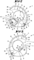
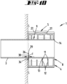
- the cutting device 1 is designed and constructed for operation with only one hand, and is furthermore essentially composed of a first shell part 4 and a second shell part 5, which shell parts 4 and 5 are produced in a preferred embodiment using the plastic injection molding process. and a cutting blade 26 which, in the illustrated embodiment, is held in the first shell part 4.
- the shell parts 4 and 5 are connected to each other in a hinge-like manner, resulting in a geometric pivot axis x.
- a total longitudinal extension L of the cutting device 1 results.
- the two shell parts 4 and 5 form shell receptacles 8 and 9 facing each other, wherein the surfaces 13 and 14 forming the shell receptacles 8 and 9 for the pipe 2 to be cut or the sleeve 3 to be cut are essentially and preferably formed by end faces 11 of ribs 12 formed in the respective shell part 4 and 5, which face in the direction of the cutting mouth 10 resulting between the shell receptacles 8 and 9.
- these surfaces 13 and 14 of the shell parts 4 and 5 are also partially formed by a geometric envelope surface H which essentially connects the end faces 11.
- the shell parts 4 and 5 can, viewed over the longitudinal extent L, each have a cross-sectional design that is essentially uniform throughout, in particular with regard to the respective shell receptacles 8 and 9, and also more preferably with regard to the outer contour.
- the shell receptacle 8 or the surface 13 of the first shell part 4 essentially forming the receptacle extends with reference to a side view according to Figure 2 or with reference to a cross-section according to Figure 5 along a concave circular arc line viewed from the outside in the direction of the cutting mouth 10.
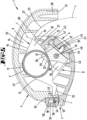
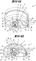
- the shell receptacle 9 of the second shell part 5 is also essentially V-shaped with respect to a side view or to a cross-section transverse to the pivot axis x, having two V-legs 15 and 16 that form an angle ⁇ of preferably about 90 degrees to one another, the V-opening of this shell receptacle 9 facing the circularly extending shell receptacle 8 of the first shell part 4. Accordingly, the cutting mouth 10 is formed between these shell receptacles 8 and 9.
- the two V-legs 15 and 16 are connected to one another in the area of a V-tip via a circular arc section 17.
- This circular arc section 17 preferably has a radius r which can correspond to approximately 0.2 to 0.4 times, furthermore approximately 0.25 to 0.3 times the radius r' of the circular-arc-shaped shell receptacle 8.
- V-legs 15 and 16 which preferably run essentially straight starting from the circular arc section 17 in the side view or in cross section, can, as is also further preferred, extend over approximately the same amount, wherein according to the embodiment shown, the V-leg 15 preferably runs into the longitudinal edge 7 near the axis of the second shell part 5 having the V-shaped shell receptacle 9.
- the other V-leg 16 merges at the end, i.e. away from the circular arc section 17, into a curve 23 facing inwards and thus essentially in the direction of the cutting mouth 10.
- This curve 23 can be viewed with reference to the side view or to the cross section be formed substantially in the shape of a circular segment, more preferably with a radius r", which can correspond to approximately 0.5 to 0.75 times, more preferably approximately 0.6 to 0.7 times the radius r' of the circular shell receptacle 8 of the first shell part 4.
- the geometry of the shell receptacle 9 of the second shell part 5 can further be selected such that a line u running perpendicular to an angle bisector w of the V-shaped shell receptacle 9 and intersecting the pivot axis x, on the one hand, intersects the shell receptacle 9 approximately in the transition region from the V-leg 16 into the curvature 23 at point P and, on the other hand, intersects the V-leg 15 running into the longitudinal edge 7 at a point P'.
- a support section 24 with a triangular cross section can be formed, which is limited on the one hand by an end section of the V-leg 15, with an extension length that can correspond to approximately a quarter or a fifth of the total length of the V-leg 16, as well as by the adjoining longitudinal edge 7 and by the geometric line u.
- a plane receiving the line u and the pivot axis x is accordingly penetrated by the area of the shell part 5 forming the support section 24 as well as by the free end section with the curvature 23.
- the vertical line described above can also delimit a depression 25 in the first shell part 4 that is essentially triangular in cross section, which depression 25 can be cross-sectionally adapted to the contour of the support section 24 of the second shell part 5.
- the depression 25 can also offer support for the support section 24, for example to form a stop limit in the inward pivoting direction of the first shell part 4.
- a movement of the radially outer free ends 19 and 20 of the shell parts 4 and 5 in the course of a pivoting of the shell parts 4 and 5 relative to one another by different outer pivot radii t a and t a' also preferably occurs.
- the ratio of the pivot radii t a and t a' relating to the pivot axis x can essentially correspond to the previously described ratio of the lengths a and b of the shell parts 4 and 5.
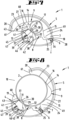
- the cross-sectional area of the cutting mouth 10 is reduced when the shorter first shell part 4 is pivoted towards the longer second shell part 5, whereby at least in the fully retracted position of the shell parts 4 and 5, and preferably already over a pivoting angle of approximately 10 to 20 degrees before reaching a preferably stop-limited retracted position, the surface 14 of the second shell part 5 forming the shell receptacle 9 is separated from the radially outer end 19 of the first shorter shell part 4 (compare Figure 15 ).
- the radially outer free end 19 of the first shorter shell part 4 is formed by individual rib-like projections 21 spaced apart from one another in the direction of the pivot axis x, which projections 21 engage in recesses 22 formed in areas between the ribs 12 of the second shell part 5.
- the front surface 60 of the first shell part 4 pointing in the pivot direction c moves within the relevant outer pivot radius t a and an inner pivot radius t i .
- These pivot radii t a and t i accordingly essentially limit the front surface 60 radially outward and radially inward.
- Such a limitation is preferably also provided for the end face 61 of the second shell part 5, which is defined in its radial extent by the outer pivot radius t a' and an inner pivot radius t i' .
- the front surface 60 of the first shell part 4 moves between the pivot radii t a and t i , which are offset radially inward from the pivot radii t a' and t i' of the second shell part 5, which also relate to the pivot axis x.
- the radially outer pivot radius t a of the first shell part 4 is accordingly preferably selected to be smaller than the radially inner pivot radius t i' of the second shell part 5.
- the dimension of the outer pivot radius t a of the first shell part 4 can thus correspond to approximately 0.5 to 0.9 times, more preferably approximately 0.7 to 0.8 times the dimension of the inner pivot radius t i' of the second shell part 5.
- a stop limitation in the retracted position of the shell parts 4 and 5 can further be achieved in that in the root region of the projections 21, adjacent regions which space the projections 21 apart from one another come into contact with the end faces 11 of the ribs 12 of the second shell part 5.
- the outer wall 26 of the first shell part 4 can intersect the contour of the shell receptacle 9 of the second shell part 5 approximately at the previously described point P.
- the shell parts 4 and 5 can have a plurality of rib formations 27, preferably spaced apart from one another in the direction of the pivot axis x. These rib formations 27 extend accordingly transversely to the pivot axis x, wherein furthermore according to the illustration in Figure 11 the rib formations 27 can extend over the entire extent of the second, longer shell part 5 transversely to the pivot axis x. Furthermore, these rib formations 27 of the second shell part 5 can continue in the first shell part 4 at least over a partial section, with an interruption by the gap 28 resulting in the connecting region V between the shell parts 4 and 5.
- the cutting blade 26 held in the first shell part 4 protrudes, in particular with its cutting edge 29, which in the illustrated embodiment runs in a straight line, at least partially beyond the surface 13 of the associated shell receptacle 8 into the cutting mouth 10.
- the circular segment shape of the shell receptacle 8 can be interrupted by the protruding cutting blade 26, with the protruding area 30 of the cutting blade 26 being depicted in an angular manner in cross-section.
- the cutting blade 26 extends, in particular in the region of the cutting edge 29, in a cutting plane S directed transversely to the pivot axis x, in which the previously described contours of the shell receptacles 8 and 9 also arise.
- the projecting area of the cutting blade 26 can, as preferred, be formed by a short leg 31 and a long leg 32, whereby the long leg 32 can be provided by a section of the cutting edge 29.
- the long leg 32 can have a length that can correspond to approximately half the total length of the cutting edge 29.
- only the section of the cutting edge 29 provided in the long leg 32 is actively cutting.
- the long leg 32 and the short leg 31 are preferably aligned at a 90 degree angle to each other, wherein in particular the long leg 32 formed by a partial section of the cutting edge 29 can enclose an acute angle ⁇ of about 30 to 45 degrees to a tangent T of the circular arc of the shell receptacle 8.
- the cutting edge 29, starting from the surface 13 of the shell holder 8 is inclined away from the pivot axis x in the direction of the free radial end 19.
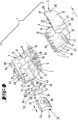
- the cutting blade 26 is further preferably arranged in a replaceable blade carrier 33.
- the holder of the cutting blade 26 is preferably achieved as a result of a screw connection, wherein the relevant screw 35 passes through the cover plate 34 and the cutting blade 26 in the region of a bore 36 for threaded engagement in a threaded bore in the blade carrier 33.
- the screw axis is preferably aligned in the same direction as the pivot axis x.
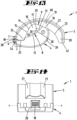
- the cover plate 34, as well as the cutting blade 26 can have pin-like projections 50 adjacent to a bore 53 for the screw 35, for reaching through openings 51 on the blade side and for engaging in pot-like recesses 52 in the blade carrier 30 (see Figures 4 and 15 ).
- the surface of the knife carrier 33 and the cover plate 34 facing the cutting mouth 10 is adapted to the circular section-shaped course of the shell holder 8 with respect to a cross section through the cutting device 1, or with respect to a plane running parallel to the cutting plane S, so that the surface forming the shell holder 8 13 essentially continues in the area of the knife carrier 33. This results in a circular curved surface 37 or 38 on the upper side of the knife carrier 33 or the cover plate 34.
- the knife carrier 33 is furthermore arranged in the first shell part 4 so as to be movable, in particular displaceable, in the direction of the pivot axis x, wherein the arrangement position is further preferably secured by a screw 39 which passes through the shell part 4 perpendicular to the displacement direction f of the knife carrier 33 and is accessible from the outside.
- the receptacle 40 in the knife carrier 33 for the screw 39 extends accordingly transversely to the displacement direction f or to the pivot axis x.
- the knife carrier 33 can be guided in the shell part 4 in a rail-like manner, for which purpose groove-like guide receptacles 41 and 42 extending in the direction of the pivot axis x are provided in the shell part 4.
- These guide receptacles 41 and 42 are preferably provided on both sides with respect to a cross section, but at different heights in a direction perpendicular to the displacement direction f.
- the knife carrier 33 has a guide projection 43 on the side. This engages in an alignment of the knife carrier 33 as shown in the Figures 1 to 8 into the lower guide receptacle 41, which is further spaced from the surface 13 of the shell receptacle 8, while a bottom-side support section 44, which is approximately triangular in cross-section, is guided in a depression 46 formed on the bottom side of the carrier receptacle 45.
- the cutting knife 26 is preferably substantially centrally located along the longitudinal extension L of the shell part 4 arranged, wherein the surface 37 of the knife carrier 33 complements the surface 13 of the first shell part 4 forming the shell receptacle 8.
- the knife carrier 33 can essentially be turned around an axis directed in the direction of the screw 39, so that the cutting knife 26 is arranged close to the edge of the shell part 4. This results in a spacing from the shell edge 49 depending on the thickness of the cover plate 34 holding the cutting knife 26. There can be a distance d between the shell edge 49 and the cutting edge 29 of, for example, 2 to 5 mm, further, for example, about 3 mm (see Figure 10 ).
- the cutting device 1 can be used in particular to cut sleeves 3, for example so-called drip sleeves, to length.
- the guide projection 43 engages in the further guide receptacle 42, which is spaced closer to the surface 13 of the shell receptacle 8, while the support section 44 is supported at the tip in a further depression 47 of the carrier receptacle 45, which is triangular in cross section.
- the cutting knife 26, in particular the cutting edge 29, projects further than the central arrangement of the cutting knife 26, with the further surface 38 of the knife carrier 33 supplementing the surface 13 of the shell receptacle 8.
- a dimension e between the transition area of the V-legs 15 and 16 and the intersection point of an angle bisector between the legs 15 and 16 and the surface of the shell receptacle 8 corresponds to approximately 1.3 to 2 times, further approximately 1.5 times the dimension e in the central and related on the carrier holder 45 lower arrangement of the cutting blade 26 (compare Figure 15 ).
- the surfaces 37 and 38 of the knife carrier 33 extend in a sickle-like or roof-like manner.
- the Figures 9 and 10 show the use of the cutting device 1 with the cutting blade 26 arranged centrally for cutting pipes 2 to length during the processing of pipes 2 of different diameters.
- the cutting direction g in which the cutting device 1 is rotated around the pipe 2 or the sleeve 3 in the direction of the cutting mouth 10 under the action of force from the outside on the shell parts 4, 5, can be specified on the outside of the cutting device 1 by symbols 48.
- the bolt 18 securing the storage position can, as shown, be penetrated by the axle body 54 forming the geometric pivot axis x in the area of an elongated hole opening 55 running perpendicular to the pivot axis x, preferably with lateral guidance through sections of the second shell part 5 close to the connecting area V.
- the bolt 18 is accommodated in a pocket-like, open-edged recess 56 of the second shell part 5.
- Cutting edge 2 Pipe 30 Executive Board 3 Sleeve 31 Short leg 4 Shell part 32 Long leg 5 Shell part 33 Knife carrier 6 Longitudinal edge 34 Cover plate 7 Longitudinal edge 35 screw 8 Shell holder 36 Drilling 9 Shell holder 37 Area 10 Cutting jaw 38 Area 11 Frontal area 39 screw 12 rib 40 Recording 13 Area 41 Lead recording 14 Area 42 Lead recording 15 V-leg 43 Leadership advantage 16 V-leg 44 Support section 17 Circular arc section 45 Carrier recording 18 Bar 46 depression 19 End 47 depression 20 End 48 symbol 21 projection 49 Shell rim 22 Deepening 50 projection 23 curvature 51 breakthrough 24 Support section 52 Deepening 25 depression 53 Drilling 26 Cutting blade 54 Axle body 27 Rib formation 55 Long hole opening 28 gap 56 Recess 57 Locking projection H Envelope area 58 Recess L Longitudinal extension 59 Recess P Point 60 Frontal area P' Point 61 Frontal area S Cutting plane T tangent V Connection area a length b length c Panning direction ⁇ angle d Distance measure ⁇ angle e Measure a
Landscapes
- Engineering & Computer Science (AREA)
- Mechanical Engineering (AREA)
- Life Sciences & Earth Sciences (AREA)
- Forests & Forestry (AREA)
- Physics & Mathematics (AREA)
- Optics & Photonics (AREA)
- Knives (AREA)
- Sawing (AREA)
- Details Of Cutting Devices (AREA)
Applications Claiming Priority (2)
| Application Number | Priority Date | Filing Date | Title |
|---|---|---|---|
| DE102021105343.9A DE102021105343A1 (de) | 2021-03-05 | 2021-03-05 | Schneidgerät zum Ablängen von Rohren oder Hülsen |
| EP22159651.3A EP4052871B1 (fr) | 2021-03-05 | 2022-03-02 | Appareil de coupe permettant de découper des tubes ou des manchons |
Related Parent Applications (2)
| Application Number | Title | Priority Date | Filing Date |
|---|---|---|---|
| EP22159651.3A Division-Into EP4052871B1 (fr) | 2021-03-05 | 2022-03-02 | Appareil de coupe permettant de découper des tubes ou des manchons |
| EP22159651.3A Division EP4052871B1 (fr) | 2021-03-05 | 2022-03-02 | Appareil de coupe permettant de découper des tubes ou des manchons |
Publications (2)
| Publication Number | Publication Date |
|---|---|
| EP4424481A2 true EP4424481A2 (fr) | 2024-09-04 |
| EP4424481A3 EP4424481A3 (fr) | 2024-12-11 |
Family
ID=80735590
Family Applications (2)
| Application Number | Title | Priority Date | Filing Date |
|---|---|---|---|
| EP22159651.3A Active EP4052871B1 (fr) | 2021-03-05 | 2022-03-02 | Appareil de coupe permettant de découper des tubes ou des manchons |
| EP24189624.0A Pending EP4424481A3 (fr) | 2021-03-05 | 2022-03-02 | Appareil de coupe permettant de découper des tubes ou des manchons |
Family Applications Before (1)
| Application Number | Title | Priority Date | Filing Date |
|---|---|---|---|
| EP22159651.3A Active EP4052871B1 (fr) | 2021-03-05 | 2022-03-02 | Appareil de coupe permettant de découper des tubes ou des manchons |
Country Status (6)
| Country | Link |
|---|---|
| EP (2) | EP4052871B1 (fr) |
| CN (1) | CN115007945A (fr) |
| DE (2) | DE102021105343A1 (fr) |
| ES (1) | ES2989037T3 (fr) |
| PL (1) | PL4052871T3 (fr) |
| TW (1) | TWI909007B (fr) |
Families Citing this family (2)
| Publication number | Priority date | Publication date | Assignee | Title |
|---|---|---|---|---|
| DE102022003899A1 (de) | 2022-10-21 | 2024-05-02 | Ralf Plonski | Schneidegerät für Kartuschen (Silikon, Acryl usw.) damit diese in Verbindung mit neuem Auspressvorsatz immer wieder auch nach Teileintrocknung/Erhärten entleert werden können so erlangt man auch völlig Restenleerte Kartuschen/Recycling Materalinhalt kann völlig verarbeitet werden |
| CN117862915A (zh) * | 2024-02-22 | 2024-04-12 | 江西东驰新能源产业有限公司 | 钠电池生产用定位设备及定位方法 |
Citations (2)
| Publication number | Priority date | Publication date | Assignee | Title |
|---|---|---|---|---|
| DE202014101596U1 (de) | 2014-04-04 | 2014-04-29 | Klaus Knipping Gmbh | Vorrichtung zum Abisolieren von Koaxialkabeln |
| DE102017129725A1 (de) | 2017-12-13 | 2019-06-13 | Knipex-Werk C. Gustav Putsch Kg | Schneidgerät zum Ablängen von Wellrohren sowie Führungsvorsprünge in einem solchen Schneidgerät |
Family Cites Families (15)
| Publication number | Priority date | Publication date | Assignee | Title |
|---|---|---|---|---|
| DE2849733A1 (de) * | 1978-11-16 | 1980-05-29 | Horst Hartmann | Schneidgeraet zum zerkleinern von nahrungsmitteln wie fleisch, zwiebel, gemuese o.dgl. |
| CH662082A5 (en) * | 1984-02-15 | 1987-09-15 | Fischer Ag Georg | Cutting device for cutting to length a protective pipe surrounding a conduit |
| ES295257Y (es) | 1986-06-25 | 1987-08-16 | Diaz De Guerenu Aguirrebeitia Pablo | Aparato perfeccionado, para el pelado de cables electricos y similares |
| US5956853A (en) * | 1997-06-10 | 1999-09-28 | Watamura; Abe | Pipe cutting tool for plastic pipe |
| DE29810244U1 (de) * | 1998-06-10 | 1999-05-20 | Mehnert, Erich, 66399 Mandelbachtal | Kunststoffrohrschneider für Normrohrgrößen |
| US6427331B1 (en) | 2000-11-28 | 2002-08-06 | Capewell Components Company, Llc | Slitting and shaving tool for messengered cable |
| US20090158597A1 (en) | 2007-12-20 | 2009-06-25 | Tyco Healthcare Group Lp | Medical Tubing Cutter |
| JP5366656B2 (ja) * | 2009-05-22 | 2013-12-11 | 株式会社松阪鉄工所 | パイプ切断具 |
| US9089958B2 (en) * | 2011-07-01 | 2015-07-28 | Mil3 Inc. | Multi-functional tool for flexible pipe and related methods |
| DE102015011394B4 (de) * | 2015-08-31 | 2018-11-15 | Sks Welding Systems Gmbh | Vorrichtung und Verfahren zum Schneiden von Kunststoffrohren |
| EP3612364B1 (fr) * | 2017-04-20 | 2025-05-28 | Merck Patent GmbH | Outil de découpe jetable ergonomique pour essai de stérilité |
| DE102017109629A1 (de) | 2017-05-04 | 2018-11-08 | Siang Syuan Fu Enterprise Co., Ltd. | Schneidgerät |
| NL1042524B1 (en) * | 2017-08-31 | 2019-03-11 | Wavin Bv | Handheld pipe cutter comprising a securer and a method of cutting a pipe |
| GB2583554A (en) * | 2019-04-30 | 2020-11-04 | Monument Tools Ltd | Pipe cutter |
| CN111014806B (zh) * | 2020-01-03 | 2025-03-18 | 深圳市燃气集团股份有限公司 | 一种自动切管装置 |
-
2021
- 2021-03-05 DE DE102021105343.9A patent/DE102021105343A1/de active Pending
-
2022
- 2022-03-02 EP EP22159651.3A patent/EP4052871B1/fr active Active
- 2022-03-02 EP EP24189624.0A patent/EP4424481A3/fr active Pending
- 2022-03-02 ES ES22159651T patent/ES2989037T3/es active Active
- 2022-03-02 PL PL22159651.3T patent/PL4052871T3/pl unknown
- 2022-03-02 CN CN202210197829.XA patent/CN115007945A/zh active Pending
- 2022-03-02 TW TW111107446A patent/TWI909007B/zh active
- 2022-03-02 DE DE202022105079.1U patent/DE202022105079U1/de active Active
Patent Citations (2)
| Publication number | Priority date | Publication date | Assignee | Title |
|---|---|---|---|---|
| DE202014101596U1 (de) | 2014-04-04 | 2014-04-29 | Klaus Knipping Gmbh | Vorrichtung zum Abisolieren von Koaxialkabeln |
| DE102017129725A1 (de) | 2017-12-13 | 2019-06-13 | Knipex-Werk C. Gustav Putsch Kg | Schneidgerät zum Ablängen von Wellrohren sowie Führungsvorsprünge in einem solchen Schneidgerät |
Also Published As
| Publication number | Publication date |
|---|---|
| EP4052871A3 (fr) | 2022-12-07 |
| EP4052871B1 (fr) | 2024-08-28 |
| EP4424481A3 (fr) | 2024-12-11 |
| TWI909007B (zh) | 2025-12-21 |
| EP4052871A2 (fr) | 2022-09-07 |
| ES2989037T3 (es) | 2024-11-25 |
| PL4052871T3 (pl) | 2025-01-13 |
| TW202235240A (zh) | 2022-09-16 |
| DE202022105079U1 (de) | 2022-09-19 |
| CN115007945A (zh) | 2022-09-06 |
| DE102021105343A1 (de) | 2022-09-08 |
Similar Documents
| Publication | Publication Date | Title |
|---|---|---|
| EP3849749B1 (fr) | Outil de pressage | |
| EP0729395B2 (fr) | Porte-outils d'usinage par enlevement de copeaux | |
| EP3655189B1 (fr) | Outil pour découper une pièce | |
| EP4052871B1 (fr) | Appareil de coupe permettant de découper des tubes ou des manchons | |
| EP3326251B1 (fr) | Outil de dénudage | |
| EP1754561B1 (fr) | Dispositif de coupe | |
| WO2019207054A1 (fr) | Pince | |
| EP4104263B1 (fr) | Outil de coupe de type pince | |
| DE3136406C2 (fr) | ||
| DE69923362T2 (de) | Werkzeug zur spanabhebenden Bearbeitung | |
| EP3723928B1 (fr) | Dispositif de coupe pour couper des tubes ondulés à longueur et guidage des saillies dans un tel dispositif de coupe | |
| WO1999012680A1 (fr) | Outil d'usinage | |
| WO2020253958A1 (fr) | Système de buses pour machine textile, système de vis pour système de fixation rapide et machine textile équipée du système de buses | |
| EP1816716A2 (fr) | Outil à dénuder | |
| DE10233856A1 (de) | Vorrichtung zum Trennen von Rohren | |
| DE2421011A1 (de) | Werkzeug, insbesondere zur bearbeitung von rohren | |
| EP2845693B1 (fr) | Système adaptateur pour un outil | |
| DE202022100251U1 (de) | Winkelanschlag | |
| EP3366399A1 (fr) | Appareil électrique portatif | |
| DE3325552C2 (fr) | ||
| EP0442004B1 (fr) | Couteau à lames interchangeables | |
| DE102024102186A1 (de) | Entgratwerkzeug für rohrförmige Werkstücke | |
| DE102022129901A1 (de) | Handbetätigbares Schneidwerkzeug | |
| DE102023124156A1 (de) | Schneidwerkzeug |
Legal Events
| Date | Code | Title | Description |
|---|---|---|---|
| PUAI | Public reference made under article 153(3) epc to a published international application that has entered the european phase |
Free format text: ORIGINAL CODE: 0009012 |
|
| STAA | Information on the status of an ep patent application or granted ep patent |
Free format text: STATUS: THE APPLICATION HAS BEEN PUBLISHED |
|
| AC | Divisional application: reference to earlier application |
Ref document number: 4052871 Country of ref document: EP Kind code of ref document: P |
|
| AK | Designated contracting states |
Kind code of ref document: A2 Designated state(s): AL AT BE BG CH CY CZ DE DK EE ES FI FR GB GR HR HU IE IS IT LI LT LU LV MC MK MT NL NO PL PT RO RS SE SI SK SM TR |
|
| REG | Reference to a national code |
Ref country code: DE Ref legal event code: R079 Free format text: PREVIOUS MAIN CLASS: B26D0005100000 Ipc: B26D0003160000 |
|
| PUAL | Search report despatched |
Free format text: ORIGINAL CODE: 0009013 |
|
| AK | Designated contracting states |
Kind code of ref document: A3 Designated state(s): AL AT BE BG CH CY CZ DE DK EE ES FI FR GB GR HR HU IE IS IT LI LT LU LV MC MK MT NL NO PL PT RO RS SE SI SK SM TR |
|
| RIC1 | Information provided on ipc code assigned before grant |
Ipc: B26D 5/10 20060101ALI20241104BHEP Ipc: B23D 21/06 20060101ALI20241104BHEP Ipc: B26D 7/26 20060101ALI20241104BHEP Ipc: B26D 3/16 20060101AFI20241104BHEP |
|
| STAA | Information on the status of an ep patent application or granted ep patent |
Free format text: STATUS: REQUEST FOR EXAMINATION WAS MADE |
|
| 17P | Request for examination filed |
Effective date: 20250506 |