EP4414263A1 - Flugvorrichtung - Google Patents
Flugvorrichtung Download PDFInfo
- Publication number
- EP4414263A1 EP4414263A1 EP22877680.3A EP22877680A EP4414263A1 EP 4414263 A1 EP4414263 A1 EP 4414263A1 EP 22877680 A EP22877680 A EP 22877680A EP 4414263 A1 EP4414263 A1 EP 4414263A1
- Authority
- EP
- European Patent Office
- Prior art keywords
- power transmission
- transmission shaft
- crankshaft
- engine
- flight device
- Prior art date
- Legal status (The legal status is an assumption and is not a legal conclusion. Google has not performed a legal analysis and makes no representation as to the accuracy of the status listed.)
- Pending
Links
Images

Classifications
-
- B—PERFORMING OPERATIONS; TRANSPORTING
- B64—AIRCRAFT; AVIATION; COSMONAUTICS
- B64C—AEROPLANES; HELICOPTERS
- B64C27/00—Rotorcraft; Rotors peculiar thereto
- B64C27/04—Helicopters
- B64C27/12—Rotor drives
-
- B—PERFORMING OPERATIONS; TRANSPORTING
- B64—AIRCRAFT; AVIATION; COSMONAUTICS
- B64C—AEROPLANES; HELICOPTERS
- B64C27/00—Rotorcraft; Rotors peculiar thereto
- B64C27/04—Helicopters
- B64C27/12—Rotor drives
- B64C27/14—Direct drive between power plant and rotor hub
-
- B—PERFORMING OPERATIONS; TRANSPORTING
- B64—AIRCRAFT; AVIATION; COSMONAUTICS
- B64U—UNMANNED AERIAL VEHICLES [UAV]; EQUIPMENT THEREFOR
- B64U10/00—Type of UAV
- B64U10/10—Rotorcrafts
- B64U10/13—Flying platforms
-
- B—PERFORMING OPERATIONS; TRANSPORTING
- B64—AIRCRAFT; AVIATION; COSMONAUTICS
- B64U—UNMANNED AERIAL VEHICLES [UAV]; EQUIPMENT THEREFOR
- B64U50/00—Propulsion; Power supply
- B64U50/10—Propulsion
- B64U50/11—Propulsion using internal combustion piston engines
-
- B—PERFORMING OPERATIONS; TRANSPORTING
- B64—AIRCRAFT; AVIATION; COSMONAUTICS
- B64U—UNMANNED AERIAL VEHICLES [UAV]; EQUIPMENT THEREFOR
- B64U50/00—Propulsion; Power supply
- B64U50/20—Transmission of mechanical power to rotors or propellers
-
- B—PERFORMING OPERATIONS; TRANSPORTING
- B64—AIRCRAFT; AVIATION; COSMONAUTICS
- B64U—UNMANNED AERIAL VEHICLES [UAV]; EQUIPMENT THEREFOR
- B64U10/00—Type of UAV
- B64U10/10—Rotorcrafts
- B64U10/13—Flying platforms
- B64U10/16—Flying platforms with five or more distinct rotor axes, e.g. octocopters
-
- B—PERFORMING OPERATIONS; TRANSPORTING
- B64—AIRCRAFT; AVIATION; COSMONAUTICS
- B64U—UNMANNED AERIAL VEHICLES [UAV]; EQUIPMENT THEREFOR
- B64U50/00—Propulsion; Power supply
- B64U50/10—Propulsion
- B64U50/19—Propulsion using electrically powered motors
-
- F—MECHANICAL ENGINEERING; LIGHTING; HEATING; WEAPONS; BLASTING
- F02—COMBUSTION ENGINES; HOT-GAS OR COMBUSTION-PRODUCT ENGINE PLANTS
- F02B—INTERNAL-COMBUSTION PISTON ENGINES; COMBUSTION ENGINES IN GENERAL
- F02B61/00—Adaptations of engines for driving vehicles or for driving propellers; Combinations of engines with gearing
- F02B61/04—Adaptations of engines for driving vehicles or for driving propellers; Combinations of engines with gearing for driving propellers
-
- Y—GENERAL TAGGING OF NEW TECHNOLOGICAL DEVELOPMENTS; GENERAL TAGGING OF CROSS-SECTIONAL TECHNOLOGIES SPANNING OVER SEVERAL SECTIONS OF THE IPC; TECHNICAL SUBJECTS COVERED BY FORMER USPC CROSS-REFERENCE ART COLLECTIONS [XRACs] AND DIGESTS
- Y02—TECHNOLOGIES OR APPLICATIONS FOR MITIGATION OR ADAPTATION AGAINST CLIMATE CHANGE
- Y02T—CLIMATE CHANGE MITIGATION TECHNOLOGIES RELATED TO TRANSPORTATION
- Y02T50/00—Aeronautics or air transport
- Y02T50/60—Efficient propulsion technologies, e.g. for aircraft
Definitions
- the present invention relates to a flight device, and relates particularly to a socalled parallel hybrid flight device in which a main rotor is drivingly driven by an engine and a sub-rotor is rotated by a motor.
- An unmanned flight device capable of flying in the air has been conventionally known. Such a flight device can fly in the air by using thrusts of rotors that rotate about vertical axes.
- the field of transport, the field of surveying, the field of imaging, and the like are conceivable as the fields to which such a flight device is applied.
- a surveying device or an imaging device is attached to the flight device. Applying the flight device to such fields enables transport, imaging, and surveying to be performed in a region in which a person cannot enter by causing the flight device to fly in such regions.
- Inventions relating to such a flight device are described in, for example, Patent Literature 1 and Patent Literature 2.
- a flight device carrying an engine In a general flight device, the above-mentioned rotors are rotated by electric power supplied from a storage battery mounted in the flight device.
- a flight device carrying an engine since a supply amount of energy is not always sufficient in the supply of electric power by the storage battery, a flight device carrying an engine has appeared to achieve continuous flight over a long period.
- a power generator is rotated by drive force of the engine, and the rotors are rotationally driven by electric power generated by this power generator. Since the engine and the power generator are connected in series in a path in which energy is supplied from a power source to the rotors, the flight device with such a configuration is also referred to as series drone. Performing imaging and surveying by using such a flight device enables imaging and surveying to be performed over a wide area.
- Patent Literature 3 describes a flight device carrying an engine.
- the present invention has been made in view of the above-mentioned circumstances, and an object of the present invention is to provide a flight device in which a mechanism for transmitting power is simplified.
- a flight device of the present invention includes an airframe, a main rotor, an engine, and a power transmission shaft, the main rotor is rotated to generate drive force that causes the airframe to lift, the engine includes a crankshaft, the power transmission shaft is connected to the crankshaft, the engine rotates the main rotor via the power transmission shaft, when a direction in which the flight device moves forward is referred to as first direction and a direction orthogonal to the first direction is referred to as second direction, the power transmission shaft is tilted with respect to the second direction.
- the flight device of the present invention includes the airframe, the main rotor, the engine, and the power transmission shaft, the main rotor is rotated to generate the drive force that causes the airframe to lift, the engine includes the crankshaft, the power transmission shaft is connected to the crankshaft, the engine rotates the main rotor via the power transmission shaft, when the direction in which the flight device moves forward is referred to as first direction and the direction orthogonal to the first direction is referred to as second direction, the power transmission shaft is tilted with respect to the second direction.
- the main rotor since the main rotor is rotated via the power transmission shaft connected to the crankshaft of the engine, a gear between the crankshaft and the power transmission shaft can be eliminated. Accordingly, it is possible to simplify the structure of a drive system of the flight device and reduce loss of power due to the gear.
- a configuration of a flight device of the present embodiment is described below with reference to the drawings.
- parts with the same configurations are denoted by the same reference numerals, and repeated description is omitted. Note that, although directions of up, down, front, rear, left, and right are used in the following description, these directions are for convenience of description.
- the flight device 10 is also referred to as drone.
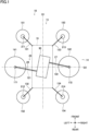
- Fig. 1 is a schematic diagram illustrating the flight device 10.
- a first direction D 1 is a direction in which the flight device 10 moves forward or backward.
- a second direction D2 is a direction orthogonal to the first direction D1.
- the first direction D1 is the front-rear direction
- the second direction D2 is the left-right direction.
- the flight device 10 includes an airframe 19, main rotors 14, an engine 30, and power transmission shafts 25.
- the flight device 10 is a parallel hybrid drone that includes two parallel drive systems of an electric drive system and a mechanical drive system.
- the electric drive system is a drive system that rotates motors 21 and sub-rotors 15 to be described later.
- the mechanical drive system is a drive system that rotates the main rotors 14 to be described later.
- the airframe 19 is a main body that supports various devices forming the flight device 10, and is made of a synthetic resin, a metal, or a composite material of the synthetic resin and the metal.
- the main rotors 14 rotate to generate drive force that causes the airframe 19 to lift.
- the main rotors 14 include a first main rotor 141 configured to be rotated by power transmitted via a first power transmission shaft 26 to be described later and a second main rotor 142 configured to be rotated by power transmitted via a second power transmission shaft 27 to be described later.
- the first main rotor 141 is arranged on the left side of the airframe 19.
- the second main rotor 142 is arranged on the right side of the airframe 19. In this case, the rotating directions of the first main rotor 141 and the second main rotor 142 are opposite to each other, and the first main rotor 141 and the second main rotor 142 rotate at the same rotating speed.
- the engine 30 mechanically rotates the main rotors 14 via the power transmission shafts 25.
- the engine 30 is housed in the airframe 19 and rotates the first main rotor 141 and the second main rotor 142 at a predetermined speed.
- the first main rotor 141 and the second main rotor 142 are drivingly connected to the engine 30 by the power transmission shafts 25 and the like to be described later.
- the engine 30 includes a first engine part 40 and a second engine part 41.
- the power transmission shafts 25 includes the first power transmission shaft 26 connected to a first crankshaft 42 and the second power transmission shaft 27 connected to a second crankshaft 45.
- the first power transmission shaft 26 is, for example, a steel rod. An end portion of the first power transmission shaft 26 on the airframe 19 side is connected to a drive shaft of the engine 30, and an outer end of the first power transmission shaft 26 is connected to a gear 171.
- the gear 171 is, for example, a bevel gear, and converts the transmitted rotating force to rotating force about a vertical axis.
- the first main rotor 141 is rotated by such rotating force.
- the first power transmission shaft 26 is housed in a first main frame 121.
- the first main frame 121 is a supporting member that connects the engine 30 and the first main rotor 141 to each other.
- a schematic configuration of the second power transmission shaft 27 is substantially the same as that of the first power transmission shaft 26.
- An end portion of the second power transmission shaft 27 on the airframe 19 side is connected to a drive shaft of the engine 30, and an outer end of the first power transmission shaft 26 is connected to a gear 172.
- a configuration of the gear 172 is similar to the gear 171.
- the first power transmission shaft 26 is housed in a second main frame 122.
- the second main frame 122 is a supporting member that connects the engine 30 and the second main rotor 142 to each other.
- the flight device 10 includes the sub-rotors 15.
- the sub-rotors 15 includes a sub-rotor 151 to a sub-rotor 154.
- the sub-rotor 151 is arranged on the front-left side of the airframe 19, is connected to the airframe 19 via a sub-frame 131, and is rotated by a motor 211.
- the sub-rotor 152 is arranged on the rear-left side of the airframe 19, is connected to the airframe 19 via a sub-frame 132, and is rotated by a motor 212.
- the sub-rotor 153 is arranged on the front-right side of the airframe 19, is connected to the airframe 19 via a sub-frame 133, and is rotated by a motor 213.
- the sub-rotor 154 is arranged on the rear-right side of the airframe 19, is connected to the airframe 19 via a sub-frame 134, and is rotated by a motor 214.
- first power transmission shaft 26 and the second power transmission shaft 27 are tilted with respect to the second direction D2. Moreover, the first power transmission shaft 26 and the second power transmission shaft 27 are substantially parallel to each other.
- the first power transmission shaft 26 is arranged to be tilted forward while extending toward the left side. This allows a crankshaft being the drive shaft of the engine 30 to be used as the first main frame 121 as it is. Accordingly, only the gear 171 is present between the engine 30 and the first main rotor 141 as a transmission device. This can simplify a transmission mechanism present between the engine 30 and the first main rotor 141, and reduce loss of drive energy.
- the second power transmission shaft 27 is tilted rearward while extending toward the right side. This allows the drive shaft of the engine 30 to be used as the second main frame 122 as it is. Accordingly, only the gear 172 is present between the engine 30 and the second main rotor 142 as a transmission device. This can simplify a transmission mechanism present between the engine 30 and the second main rotor 142, and reduce loss of drive energy.
- the rotation center of the first main rotor 141 and the rotation center of the second main rotor 142 can be arranged along the second direction D2. Accordingly, it is possible to configure the configuration of the flight device 10 to be line-symmetric with respect to the first direction D1 and optimize weight distribution.
- Fig. 2 is a diagram illustrating the flight device 10, and is a block diagram illustrating a connection configuration of various units.
- the flight device 10 includes an arithmetic control unit 31, the engine 30, power generators 16, a battery 18, electric power converters 24, the motors 21, and the sub-rotors 15.
- the arithmetic control unit 31 includes a CPU, a ROM, a RAM, and the like, and controls behaviors of various devices forming the flight device 10 based on inputs from various types of sensors and controllers that are not illustrated herein. Moreover, the arithmetic control unit 31 is also a flight controller that controls the number of revolutions of each of the main rotors 14 and the sub-rotors 15 based on the inputs from the various types of sensors.
- the engine 30 operates based on an input signal from the arithmetic control unit 31, and generates energy for causing the flight device 10 to fly.
- a specific configuration of the engine 30 is described later with reference to Fig. 3 .
- the power generators 16 are devices that generate electric power by using part of the drive force of the engine 30, and includes a power generator 161 and a power generator 162.
- the power generator 161 is driven by the first engine part 40 of the engine 30 to be described later.
- the power generator 162 is driven by the second engine part 41 of the engine 30 to be described later.
- the battery 18 is provided between the power generators 16 and the electric power converters 24.
- the battery 18 is charged by the power generators 16. Electric power discharged from the battery 18 is supplied to the electric power converters 24 to be described later.
- the electric power converters 24 are provided to correspond to the respective sub-rotors 15. Converters and Inverters that temporarily convert AC electric power supplied from the power generator 162 to DC electric power and then convert the DC electric power to AC electric power of a predetermined frequency can be adopted as the electric power converters 24. Moreover, inverters that convert DC electric power supplied from the battery 18 to a predetermined frequency can be adopted as the electric power converters 24. Specifically, the electric power converters 24 includes an electric power converter 241, an electric power converter 242, an electric power converter 243, and an electric power converter 244.
- the motors 21 are provided to correspond to the respective sub-rotors 15, and includes the motor 211, the motor 212, the motor 213, and the motor 214.
- the motor 211, the motor 212, the motor 213, and the motor 214 rotate at predetermined speeds by using electric power supplied from the electric power converter 241, the electric power converter 242, the electric power converter 243, and the electric power converter 244, respectively.
- the sub-rotors 15 include the sub-rotor 151, the sub-rotor 152, the sub-rotor 153, and the sub-rotor 154.
- the sub-rotor 151, the sub-rotor 152, the sub-rotor 153, and the sub-rotor 154 are rotated by the motor 211, the motor 212, the motor 213, and the motor 214, respectively.
- the flight device 10 operates in a hovering state, an ascending/descending state, or a horizontal movement state.
- the flight device 10 rotates the main rotors 14 by using the drive force generated by the engine 30 based on an instruction from the arithmetic control unit 31, and the flight device 10 is lifted to a predetermined position in the air.
- each of the sub-rotors 15 is rotated based on an instruction from the arithmetic control unit 31.
- the arithmetic control unit 31 sets the rotation speed of each of the motors 21 and the sub-rotors 15 to a predetermined speed by controlling a corresponding one of the electric power converters 24 such that the flight device 10 can maintain predetermined altitude and attitude.
- the flight device 10 In the ascending/descending state, the flight device 10 ascends or descends by controlling the number of revolutions of the engine 30. Also in this case, the arithmetic control unit 31 sets the rotation speed of each of the motors 21 and the sub-rotors 15 to a predetermined speed by controlling a corresponding one of the electric power converters 24 such that the flight device 10 can maintain predetermined altitude and attitude.
- the arithmetic control unit 31 sets the flight device 10 to a tilted state by controlling each of the electric power converters 24 to control the number of revolutions of a corresponding set of the motor 21 and the sub-rotor 15. Also in this case, the arithmetic control unit 31 rotates the main rotors 14 at a predetermined speed by controlling a drive state of the engine 30.
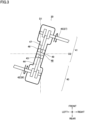
- Fig. 3 is a diagram illustrating a configuration and arrangement of the engine 30 in the flight device 10.
- the engine 30 includes the first engine part 40 and the second engine part 41.
- the first engine part 40 and the second engine part 41 are arranged to be opposed to each other, the first engine part 40 is arranged on the rear-left side, and the second engine part 41 is arranged on the front-right side.
- the first engine part 40 includes a first piston 43 configured to reciprocate, the first crankshaft 42 configured to convert a reciprocating motion of the first piston 43 to a rotating motion, and a first connecting rod 44 configured to rotatably link the first piston 43 and the first crankshaft 42 to each other.
- the second engine part 41 includes a second piston 46 configured to reciprocate, the second crankshaft 45 configured to convert a reciprocating motion of the second piston 46 to a rotating motion, and a second connecting rod 47 configured to rotatably link the second piston 46 and the second crankshaft 45 to each other.
- the first piston 43 of the first engine part 40 and the second piston 46 of the second engine part 41 share a combustion chamber 48.
- the first piston 43 and the second piston 46 reciprocate inside one communicating cylinder. Accordingly, it is possible to reduce a stroke amount and achieve a high expansion ratio of a mixture gas in the combustion chamber 48 by causing the first engine part 40 and the first piston 43 to simultaneously stroke toward a center portion.
- a volume space communicating with the combustion chamber 48 is formed in the engine 30, and a spark plug is arranged in this volume space. Moreover, an intake port and an exhaust port that are not illustrated herein are formed in the combustion chamber 48. An air-fuel mixture including fuel such as gasoline is introduced into the combustion chamber 48 from the intake port, and an exhaust gas after combustion is exhausted from the combustion chamber to the outside via the exhaust port.
- the engine 30 with the above-mentioned configuration operates as follows. First, in an intake stroke, the first piston 43 and the second piston 46 move inside a cylinder 49 from a center portion toward the outer sides to introduce the air-fuel mixture being a mixture of fuel and air into the cylinder 49. Next, in a compression stroke, the first piston 43 and the second piston 46 are pushed toward the center portion by inertia of the rotating first crankshaft 42 and second crankshaft 45, and the air-fuel mixture is compressed inside the cylinder 49. Next, in a combustion stroke, the not-illustrated spark plug ignites the air-fuel mixture in the combustion chamber 48, and the air-fuel mixture combusts inside the cylinder 49.
- first piston 43 and the second piston 46 This causes the first piston 43 and the second piston 46 to be pushed to outer end portions which are bottom dead centers. Then, in an exhaust stroke, the first piston 43 and the second piston 46 are pushed toward the inner side by the inertia of the rotating first crankshaft 42 and second crankshaft 45, and the gas that is present inside the cylinder 49 after the combustion is exhausted to the outside.
- the stroke can be divided between two pistons of the first piston 43 and the second piston 46 that reciprocate inside one cylinder 49. Accordingly, a compression ratio of the mixture gas can be set higher than that in a normal gasoline engine. Moreover, since the first piston 43 and the second piston 46 are opposed to each other inside the cylinder 49, a cylinder head necessary in a general engine is unnecessary, and the configuration of the engine 30 is simple and lightweight. Furthermore, the members forming the engine 30, specifically, the first piston 43, the second piston 46, the first crankshaft 42, the second crankshaft 45, and the like are arranged to be opposed to one another and operate in an opposed manner.
- vibrations generated by the members of the engine 30 are cancelled out, and a vibration generated from the entire engine 30 to the outside can be reduced.
- mounting the engine 30 with a such a structure in the flight device 10 can achieve size reduction, weight reduction, and vibration reduction of the flight device 10.
- reducing the vibration can prevent adverse effects on arithmetic control devices for attitude control, motor output control, and the like and on precision equipment such as a GPS sensor.
- the first crankshaft 42 of the first engine part 40 doubles as the first power transmission shaft 26. Specifically, the first crankshaft 42 extends to the center of the first main rotor 141 illustrated in Fig. 1 , and is connected to the gear 171. Similarly, the second crankshaft 45 of the second engine part 41 doubles as the second power transmission shaft 27. Specifically, the second crankshaft 45 extends to the center of the second main rotor 142 illustrated in Fig. 1 , and is connected to the gear 172.
- the engine 30 includes an opposite-rotation synchronization mechanism not illustrated herein.
- the opposite-rotation synchronization mechanism causes the rotating directions of the first crankshaft 42 and the second crankshaft 45 to be opposite to each other.
- the opposite-rotation synchronization mechanism synchronizes the reciprocating motions of the first piston 43 and the second piston 46. Accordingly, in the engine 30, the rotating directions of the first crankshaft 42 and the second crankshaft 45 are opposite to each other in principle.
- the first power transmission shaft 26 being an extended shaft of the first crankshaft 42
- the second power transmission shaft 27 being an extended shaft of the second crankshaft 45 rotate in opposite directions without being provided with a dedicate reversal mechanism.
- the first main rotor 141 and the second main rotor 142 illustrated in Fig. 1 are rotated in opposite directions at the same rotating speed without being provided with the dedicated reversal mechanism.
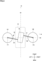
- Fig. 4 is a schematic diagram illustrating the flight device 10 according to another mode.
- a basic configuration of the flight device 10 illustrated in Fig. 4 is substantially the same as that of the flight device 10 illustrated in Fig. 1 , and is different in that the flight device 10 illustrated in Fig. 4 includes no sub-rotors 15.
- the flight device 10 illustrated in Fig. 4 is an engine drone that includes only the main rotors 14 configured to be mechanically rotated by the drive force of the engine.
- the flight device 10 includes only the main rotors 14 as a mechanism for lifting the airframe 19.
- the main rotors 14 generate the thrust for lifting the airframe 19 into the air, and are also responsible for control of the position and the attitude.
- the main rotors 14 include control mechanisms for controlling the position and the attitude of the flight device 10. For example, pitch control in which pitch angles of the blades of the main rotors 14 are appropriately changed can be adopted as such control mechanisms.
- the control mechanisms of the main rotors 14 allow the flight device 10 to perform the hovering state, the ascending state, the descending state, and the horizontal movement state also in the case where the flight device 10 includes no sub-rotors 15.
- the present embodiment described above can have the following main effects.
- first main rotor 141 and the second main rotor 142 are rotated via the first power transmission shaft 26 and the second power transmission shaft 27 that are connected to the first crankshaft 42 and the second crankshaft 45 of the engine 30, gears in the drive system can be eliminated. Accordingly, it is possible to simplify the structure of the drive system of the flight device 10 and reduce the loss of power due to gears.
- the first engine part 40 and the second engine part 41 share the combustion chamber 48.
- the first engine part 40 and the second engine part 41 may individually have combustion chambers.
- the engine 30 includes the first engine part 40 and the second engine part 41.
- the engine 30 may be formed only of the first engine part 40.
- the power from the first engine part 40 is transmitted to the second power transmission shaft 27 via a gear.
- the first power transmission shaft 26 is formed as the extended shaft of the first crankshaft 42 illustrated in Fig. 3 .
- a joint that is unable to rotate relative to the first power transmission shaft 26 may be formed in the middle of the first power transmission shaft 26.
- a clutch may be provided between the first crankshaft 42 on the flight device 10 side and the first power transmission shaft 26 on the first main rotor 141 side, that is between the first crankshaft 42 and the first power transmission shaft 26.
- a centrifugal clutch may be adopted as this clutch. This provides the following effects.
- the clutch When the number of revolutions of the engine 30 is below a predetermined number, the clutch is set to a disconnected state to prevent power transmission from the first crankshaft 42 to the first power transmission shaft 26. Meanwhile, when the number of revolutions of the engine 30 is equal to or above the predetermined number, the clutch is set to a connected state to allow power transmission from the first crankshaft 42 to the first power transmission shaft 26.
- the second crankshaft 45 and the second power transmission shaft 27 illustrated in Fig. 3 Such matters also apply to the second crankshaft 45 and the second power transmission shaft 27 illustrated in Fig. 3 .
Landscapes
- Engineering & Computer Science (AREA)
- Mechanical Engineering (AREA)
- Aviation & Aerospace Engineering (AREA)
- Chemical & Material Sciences (AREA)
- Combustion & Propulsion (AREA)
- Remote Sensing (AREA)
- Transmission Devices (AREA)
- Hybrid Electric Vehicles (AREA)
Applications Claiming Priority (2)
| Application Number | Priority Date | Filing Date | Title |
|---|---|---|---|
| JP2021165734A JP6979251B1 (ja) | 2021-10-07 | 2021-10-07 | 飛行装置 |
| PCT/JP2022/037465 WO2023058721A1 (ja) | 2021-10-07 | 2022-10-06 | 飛行装置 |
Publications (2)
| Publication Number | Publication Date |
|---|---|
| EP4414263A1 true EP4414263A1 (de) | 2024-08-14 |
| EP4414263A4 EP4414263A4 (de) | 2025-08-20 |
Family
ID=78815871
Family Applications (1)
| Application Number | Title | Priority Date | Filing Date |
|---|---|---|---|
| EP22877680.3A Pending EP4414263A4 (de) | 2021-10-07 | 2022-10-06 | Flugvorrichtung |
Country Status (5)
| Country | Link |
|---|---|
| US (1) | US20240336379A1 (de) |
| EP (1) | EP4414263A4 (de) |
| JP (1) | JP6979251B1 (de) |
| CN (1) | CN117295660A (de) |
| WO (1) | WO2023058721A1 (de) |
Families Citing this family (7)
| Publication number | Priority date | Publication date | Assignee | Title |
|---|---|---|---|---|
| JP7838755B2 (ja) * | 2022-03-29 | 2026-04-01 | 株式会社石川エナジーリサーチ | 飛行装置 |
| JPWO2023188266A1 (de) * | 2022-03-31 | 2023-10-05 | ||
| JP7170364B1 (ja) * | 2022-09-08 | 2022-11-14 | 株式会社石川エナジーリサーチ | 飛行装置 |
| EP4644274A1 (de) * | 2022-12-27 | 2025-11-05 | Kubota Corporation | Fliegende vorrichtung |
| JPWO2024142220A1 (de) * | 2022-12-27 | 2024-07-04 | ||
| WO2024142207A1 (ja) * | 2022-12-27 | 2024-07-04 | 株式会社クボタ | 飛行装置 |
| WO2025173192A1 (ja) * | 2024-02-15 | 2025-08-21 | 株式会社石川エナジーリサーチ | 飛行装置およびその製造方法 |
Family Cites Families (18)
| Publication number | Priority date | Publication date | Assignee | Title |
|---|---|---|---|---|
| US6672538B2 (en) * | 2002-05-23 | 2004-01-06 | Sikorsky Aircraft Corporation | Transmission for a coaxial counter rotating rotor system |
| US20090050733A1 (en) * | 2007-02-28 | 2009-02-26 | Manousos Pattakos | Simple vtol flying machine |
| FR2961041B1 (fr) | 2010-06-02 | 2012-07-27 | Parrot | Procede de commande synchronisee des moteurs electriques d'un drone telecommande a voilure tournante tel qu'un quadricoptere |
| KR101042200B1 (ko) | 2010-09-02 | 2011-06-16 | 드림스페이스월드주식회사 | Pcb를 사용한 무인 비행체 |
| JP2014240242A (ja) | 2013-06-12 | 2014-12-25 | 富士重工業株式会社 | 垂直離着陸飛行体 |
| CN104139860A (zh) * | 2014-04-23 | 2014-11-12 | 李晓宇 | 一种多轴旋翼飞行器及其传动机构 |
| US20170240273A1 (en) * | 2016-02-24 | 2017-08-24 | Melville Yuen | Fixed-wing vtol aircraft with rotors on outriggers |
| JP2017154654A (ja) * | 2016-03-03 | 2017-09-07 | 双葉電子工業株式会社 | マルチコプター |
| JP2017193321A (ja) * | 2016-04-19 | 2017-10-26 | 株式会社石川エナジーリサーチ | エンジン搭載型マルチコプター |
| CN207029535U (zh) * | 2017-02-09 | 2018-02-23 | 深圳常锋信息技术有限公司 | 一种无人机 |
| JP6707761B2 (ja) * | 2017-09-27 | 2020-06-10 | 株式会社石川エナジーリサーチ | エンジン搭載自立型飛行装置 |
| IL261236B2 (en) * | 2018-08-19 | 2023-04-01 | Aerotor Unmanned Systems Ltd | An aircraft with improved maneuverability and a method applied for that purpose |
| BR112021007411A2 (pt) * | 2018-10-17 | 2021-08-03 | Wojciech Gaj-Jablonski | motor a hidrogênio de pistão oposto e método para operação |
| JP6696658B1 (ja) * | 2018-12-21 | 2020-05-20 | 株式会社プロドローン | 無人航空機 |
| JP7229874B2 (ja) * | 2019-02-07 | 2023-02-28 | 愛三工業株式会社 | マルチコプタ |
| US20210009279A1 (en) * | 2019-07-12 | 2021-01-14 | GeoScout, Inc. | Rotary-wing vehicle and system |
| JP2021021362A (ja) * | 2019-07-29 | 2021-02-18 | 三菱重工業株式会社 | エンジン及び飛行体 |
| JP6932411B1 (ja) * | 2021-05-07 | 2021-09-08 | アラセ・アイザワ・アエロスパシアル合同会社 | 無人飛行体のエンジン装置 |
-
2021
- 2021-10-07 JP JP2021165734A patent/JP6979251B1/ja active Active
-
2022
- 2022-10-06 WO PCT/JP2022/037465 patent/WO2023058721A1/ja not_active Ceased
- 2022-10-06 US US18/681,620 patent/US20240336379A1/en active Pending
- 2022-10-06 CN CN202280032167.9A patent/CN117295660A/zh active Pending
- 2022-10-06 EP EP22877680.3A patent/EP4414263A4/de active Pending
Also Published As
| Publication number | Publication date |
|---|---|
| JP6979251B1 (ja) | 2021-12-08 |
| WO2023058721A1 (ja) | 2023-04-13 |
| US20240336379A1 (en) | 2024-10-10 |
| EP4414263A4 (de) | 2025-08-20 |
| JP2023056399A (ja) | 2023-04-19 |
| CN117295660A (zh) | 2023-12-26 |
Similar Documents
| Publication | Publication Date | Title |
|---|---|---|
| EP4414263A1 (de) | Flugvorrichtung | |
| EP4431387A1 (de) | Flugvorrichtung | |
| US12428985B2 (en) | Engine-mounted autonomous flying device | |
| EP4509403A1 (de) | Fluggerät | |
| JP7762997B2 (ja) | 飛行装置 | |
| KR101340409B1 (ko) | 하이브리드 무인비행체 | |
| EP4501795A1 (de) | Flugvorrichtung und flugvorrichtungsteuerungsverfahren | |
| WO2022172315A1 (ja) | 動力装置および移動用推進装置 | |
| JP6770767B2 (ja) | エンジン搭載自立型飛行装置 | |
| JP2019112050A (ja) | 航空機 | |
| CN120903038A (zh) | 一种双螺旋桨可折叠固定翼无人机构造方法 |
Legal Events
| Date | Code | Title | Description |
|---|---|---|---|
| STAA | Information on the status of an ep patent application or granted ep patent |
Free format text: STATUS: THE INTERNATIONAL PUBLICATION HAS BEEN MADE |
|
| PUAI | Public reference made under article 153(3) epc to a published international application that has entered the european phase |
Free format text: ORIGINAL CODE: 0009012 |
|
| STAA | Information on the status of an ep patent application or granted ep patent |
Free format text: STATUS: REQUEST FOR EXAMINATION WAS MADE |
|
| 17P | Request for examination filed |
Effective date: 20240209 |
|
| AK | Designated contracting states |
Kind code of ref document: A1 Designated state(s): AL AT BE BG CH CY CZ DE DK EE ES FI FR GB GR HR HU IE IS IT LI LT LU LV MC ME MK MT NL NO PL PT RO RS SE SI SK SM TR |
|
| DAV | Request for validation of the european patent (deleted) | ||
| DAX | Request for extension of the european patent (deleted) | ||
| A4 | Supplementary search report drawn up and despatched |
Effective date: 20250723 |
|
| RIC1 | Information provided on ipc code assigned before grant |
Ipc: B64C 39/02 20230101AFI20250717BHEP Ipc: B64C 27/08 20230101ALI20250717BHEP Ipc: B64D 27/24 20240101ALI20250717BHEP Ipc: B64U 50/20 20230101ALI20250717BHEP Ipc: B64U 50/11 20230101ALI20250717BHEP Ipc: B64C 27/12 20060101ALI20250717BHEP Ipc: B64C 27/14 20060101ALI20250717BHEP Ipc: B64U 10/13 20230101ALI20250717BHEP |