EP4431387A1 - Flugvorrichtung - Google Patents
Flugvorrichtung Download PDFInfo
- Publication number
- EP4431387A1 EP4431387A1 EP22888624.8A EP22888624A EP4431387A1 EP 4431387 A1 EP4431387 A1 EP 4431387A1 EP 22888624 A EP22888624 A EP 22888624A EP 4431387 A1 EP4431387 A1 EP 4431387A1
- Authority
- EP
- European Patent Office
- Prior art keywords
- sub
- rotor
- airframe
- main
- rotors
- Prior art date
- Legal status (The legal status is an assumption and is not a legal conclusion. Google has not performed a legal analysis and makes no representation as to the accuracy of the status listed.)
- Pending
Links
Images


Classifications
-
- B—PERFORMING OPERATIONS; TRANSPORTING
- B64—AIRCRAFT; AVIATION; COSMONAUTICS
- B64C—AEROPLANES; HELICOPTERS
- B64C27/00—Rotorcraft; Rotors peculiar thereto
- B64C27/04—Helicopters
- B64C27/08—Helicopters with two or more rotors
-
- B—PERFORMING OPERATIONS; TRANSPORTING
- B64—AIRCRAFT; AVIATION; COSMONAUTICS
- B64U—UNMANNED AERIAL VEHICLES [UAV]; EQUIPMENT THEREFOR
- B64U10/00—Type of UAV
- B64U10/10—Rotorcrafts
- B64U10/13—Flying platforms
- B64U10/16—Flying platforms with five or more distinct rotor axes, e.g. octocopters
-
- B—PERFORMING OPERATIONS; TRANSPORTING
- B64—AIRCRAFT; AVIATION; COSMONAUTICS
- B64U—UNMANNED AERIAL VEHICLES [UAV]; EQUIPMENT THEREFOR
- B64U50/00—Propulsion; Power supply
- B64U50/10—Propulsion
-
- B—PERFORMING OPERATIONS; TRANSPORTING
- B64—AIRCRAFT; AVIATION; COSMONAUTICS
- B64U—UNMANNED AERIAL VEHICLES [UAV]; EQUIPMENT THEREFOR
- B64U50/00—Propulsion; Power supply
- B64U50/10—Propulsion
- B64U50/11—Propulsion using internal combustion piston engines
-
- B—PERFORMING OPERATIONS; TRANSPORTING
- B64—AIRCRAFT; AVIATION; COSMONAUTICS
- B64U—UNMANNED AERIAL VEHICLES [UAV]; EQUIPMENT THEREFOR
- B64U50/00—Propulsion; Power supply
- B64U50/10—Propulsion
- B64U50/19—Propulsion using electrically powered motors
-
- B—PERFORMING OPERATIONS; TRANSPORTING
- B64—AIRCRAFT; AVIATION; COSMONAUTICS
- B64U—UNMANNED AERIAL VEHICLES [UAV]; EQUIPMENT THEREFOR
- B64U50/00—Propulsion; Power supply
- B64U50/20—Transmission of mechanical power to rotors or propellers
- B64U50/27—Transmission of mechanical power to rotors or propellers with a single motor serving two or more rotors or propellers
-
- Y—GENERAL TAGGING OF NEW TECHNOLOGICAL DEVELOPMENTS; GENERAL TAGGING OF CROSS-SECTIONAL TECHNOLOGIES SPANNING OVER SEVERAL SECTIONS OF THE IPC; TECHNICAL SUBJECTS COVERED BY FORMER USPC CROSS-REFERENCE ART COLLECTIONS [XRACs] AND DIGESTS
- Y02—TECHNOLOGIES OR APPLICATIONS FOR MITIGATION OR ADAPTATION AGAINST CLIMATE CHANGE
- Y02T—CLIMATE CHANGE MITIGATION TECHNOLOGIES RELATED TO TRANSPORTATION
- Y02T50/00—Aeronautics or air transport
- Y02T50/60—Efficient propulsion technologies, e.g. for aircraft
Definitions
- the present invention relates to a flight device, and relates particularly to a so-called parallel hybrid flight device in which a main rotor is drivingly driven by an engine and a sub-rotor is rotated by a motor.
- An unmanned flight device capable of flying in the air has been conventionally known. Such a flight device can fly in the air by using thrusts of rotors that rotate about vertical axes.
- the field of transport, the field of surveying, the field of imaging, and the like are conceivable as the fields to which such a flight device is applied.
- a surveying device or an imaging device is attached to the flight device. Applying the flight device to such fields enables transport, imaging, and surveying to be performed in a region in which a person cannot enter by causing the flight device to fly in such regions.
- Inventions relating to such a flight device are described in, for example, Patent Literature 1 and Patent Literature 2.
- a flight device carrying an engine In a general flight device, the above-mentioned rotors are rotated by electric power supplied from a storage battery mounted in the flight device.
- a flight device carrying an engine since a supply amount of energy is not always sufficient in the supply of electric power by the storage battery, a flight device carrying an engine has appeared to achieve continuous flight over a long period.
- a power generator is rotated by drive force of the engine, and the rotors are rotationally driven by electric power generated by this power generator. Since the engine and the power generator are connected in series in a path in which energy is supplied from a power source to the rotors, the flight device with such a configuration is also referred to as series drone. Performing imaging and surveying by using such a flight device enables imaging and surveying to be performed over a wide area.
- Patent Literature 3 describes a flight device carrying an engine.
- an air frame is lifted into the air by lift generated by rotation of the main rotor, and the position and the attitude of the airframe is controlled by lift generated by rotation of the sub-rotor.
- the present invention has been made in view of the above-mentioned circumstances, and an object of the present invention is to provide a flight device that can accurately perform attitude control by using a sub-rotor.
- a flight device of the present invention includes an airframe, an engine, a motor, a main rotor, and a sub-rotor, the engine rotates the main rotor, the motor rotates the sub-rotor, and the main rotor is arranged below the sub-rotor.
- the main rotor prevents the sub-rotor from being affected by an air flow generated by rotation of the main rotor.
- the sub-rotor can provide a thrust as designed by being rotated, and the position and the attitude of the airframe can be accurately adjusted.
- the main rotor is arranged above a bottom surface of the airframe. Accordingly, in the flight device of the present invention, arranging the main rotor above the bottom surface of the airframe allows the airframe to be stably lifted by using a thrust generated by rotation of the main rotor.
- a distance between a rotation center of the sub-rotor and a center of the airframe is longer than a distance between a rotation center of the main rotor and the center of the airframe. Accordingly, in the flight device of the present invention, securing a long distance between the rotation center of the sub-rotor and the center of the airframe allows the position and the attitude of the airframe to be accurately controlled by using a thrust generated by rotation of the sub-rotor.
- the main rotor includes a first main rotor and a second main rotor
- the sub-rotor includes a first sub-rotor, a second sub-rotor, a third sub-rotor, and a fourth sub-rotor
- the first main rotor is arranged on a left side of the airframe
- the second main rotor is arranged on a right side of the airframe
- the first sub-rotor is arranged on a front-left side of the airframe
- the second sub-rotor is arranged on a rear-left side of the airframe
- the third sub-rotor is arranged on a front-right side of the airframe
- the fourth sub-rotor is arranged on a rear-right side of the airframe.
- arranging the first main rotor and the second main rotor at positions where the airframe is provided between the first main rotor and the second main rotor allows the airframe to be lifted more stably.
- arranging the first sub-rotor to the fourth sub-rotor in the respective front, rear, left, and right corners allows the position and the attitude of the airframe to be more accurately controlled.
- a configuration of a flight device of the present embodiment is described below with reference to the drawings.
- parts with the same configurations are denoted by the same reference numerals, and repeated description is omitted. Note that, although directions of up, down, front, rear, left, and right are used in the following description, these directions are for convenience of description.
- the flight device 10 is also referred to as drone.
- Fig. 1 is a perspective view illustrating the flight device 10.
- the flight device 10 includes an airframe 19, main rotors 14, and an engine 30. Since the engine 30 is housed in the airframe 19, the engine 30 is not illustrated.
- the flight device 10 is a parallel hybrid drone including two parallel drive systems of an electric drive system and a mechanical drive system.
- the electric drive system is a drive system that rotates motors 21 and sub-rotors 15 to be described later.
- the mechanical drive system is a drive system that rotates the main rotors 14.
- the airframe 19 is a main body that supports various devices forming the flight device 10, and is made of a synthetic resin, a metal, or a composite material of the synthetic resin and the metal. Although not illustrated herein, the engine 30, power generators 16, a battery 18, and the like are arranged inside the airframe 19.
- the main rotors 14 rotate to generate drive force that causes the airframe 19 to lift.
- the main rotors 14 include a main rotor 141 and a main rotor 142.
- the main rotor 141 is a first main rotor
- the main rotor 142 is a second main rotor.
- the main rotor 141 is arranged on the left side of the airframe 19.
- the main rotor 141 is connected to the airframe 19 via a main frame 121.
- the main rotor 142 is arranged on the right side of the airframe 19.
- the main rotor 142 is connected to the airframe 19 via a main frame 122.
- the rotating directions of the main rotor 141 and the main rotor 142 are opposite to each other, and the main rotor 141 and the main rotor 142 rotate at the same rotating speed.
- the main rotor 141 and the main rotor 142 are mechanically connected to the engine 30 housed in the airframe 19.
- the main rotor 141 and the main rotor 142 are mechanically connected to the engine 30 housed in the airframe 19 via belts, power transmission rods, gears, or the like.
- the flight device 10 includes the sub-rotors 15.
- the sub-rotors 15 include a sub-rotor 151 to a sub-rotor 154.
- a first sub-rotor is the sub-rotor 151
- a second sub-rotor is the sub-rotor 152
- a third sub-rotor is the sub-rotor 153
- a fourth sub-rotor is the sub-rotor 154.
- the sub-rotor 151 is arranged on the front-left side of the airframe 19, is connected to the airframe 19 via a sub-frame 131, and is rotated by a motor 211 not illustrated herein.
- the sub-rotor 152 is arranged on the rear-left side of the airframe 19, is connected to the airframe 19 via a sub-frame 132, and is rotated by a motor 212 not illustrated herein.
- the sub-rotor 153 is arranged on the right-front side of the airframe 19, is connected to the airframe 19 via a sub-frame 133, and is rotated by a motor 213 not illustrated herein.
- the sub-rotor 154 is arranged on the right-rear side of the airframe 19, is connected to the airframe 19 via a sub-frame 134, and is rotated by a motor 214 not illustrated herein.
- the sub-frame 131 to the sub-frame 134 are formed to be longer than the main frame 121 and the main frame 122.
- the rotation centers of the sub-rotor 151 to the sub-rotor 154 are thereby farther away from a center portion of the airframe 19 than the rotation centers of the main rotor 141 and the main rotor 142 are. Control of the position and the attitude of the flight device 10 with the sub-rotor 151 to the sub-rotor 154 can be thereby performed more accurately.
- a ground contact part 25 is a portion that comes into contact with a landing surface when the flight device 10 lands.
- the ground contact part 25 is formed by combining multiple frames like the main frame 121 and the like.
- Fig. 2 is a rear view in which the flight device 10 is viewed from behind.
- the main rotors 14 are arranged below the sub-rotors 15.
- the main rotor 141 and the main rotor 142 are arranged below the sub-rotor 152 and the sub-rotor 154.
- Arranging the main rotors 14 below the sub-rotors 15 allows the control of the position and the attitude of the flight device 10 with the sub-rotors 15 to be performed more accurately.
- the main rotors 14 rotate at high speed to lift the entire flight device 10 into the air.
- downwash is generated below the main rotors 14.
- the diameter of the main rotors 14 is larger than that of the sub-rotors 15, strong downwash is generated.
- downwash is wind generated by air that is sucked in from above the main rotors 14 and blown downward by the rotation of the main rotors 14 when the flight device 10 is in flight, and spreads in a fan shape while flowing downward.
- the position and the attitude of the flight device 10 in the air can be set to predetermined position and attitude by causing each sub-rotor 15 to rotate at a predetermined rotation speed. Accordingly, an operator not illustrated herein can stably operate the flight device 10.
- the main rotors 14 are arranged above a bottom surface of the airframe 19. This allows the positions of the main rotors 14 to be set as high as possible, in an area below the sub-rotors 15, and allows the airframe 19 to be stably lifted into the air by thrusts generated by the rotation of the main rotors 14.
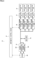
- Fig. 3 is a diagram illustrating the flight device 10, and is a block diagram illustrating a connection configuration of various units.
- the flight device 10 includes an arithmetic control unit 31, the engine 30, the power generators 16, the battery 18, electric power converters 24, the motors 21, and the sub-rotors 15.
- the arithmetic control unit 31 includes a CPU, a ROM, a RAM, and the like, and controls behaviors of various devices forming the flight device 10 based on inputs from various types of sensors and controllers that are not illustrated herein. Moreover, the arithmetic control unit 31 is also a flight controller that controls the number of revolutions of each of the main rotors 14 and the sub-rotors 15 based on the inputs from the various types of sensors and a remote control device (proportional controller) operated by the operator.
- a remote control device proportional controller
- the engine 30 operates based on an input signal from the arithmetic control unit 31, and generates energy for causing the flight device 10 to fly.
- a specific configuration of the engine 30 is described later with reference to Fig. 3 .
- the power generators 16 are devices that generate electric power by using part of the drive force of the engine 30, and include a power generator 161 and a power generator 162.
- the power generator 161 is driven by a first engine part 40 of the engine 30 to be described later.
- the power generator 162 is driven by a second engine part 41 of the engine 30 to be described later.
- the battery 18 is provided between the power generators 16 and the electric power converters 24.
- the battery 18 is charged by the power generators 16. Electric power discharged from the battery 18 is supplied to the electric power converters 24 to be described later.
- the electric power converters 24 are provided to correspond to the respective sub-rotors 15. Converters and Inverters that temporarily convert AC electric power supplied from the power generator 162 to DC electric power and then convert the DC electric power to AC electric power of a predetermined frequency can be adopted as the electric power converters 24. Moreover, inverters that convert DC electric power supplied from the battery 18 to a predetermined frequency can be adopted as the electric power converters 24. Specifically, the electric power converters 24 includes an electric power converter 241, an electric power converter 242, an electric power converter 243, and an electric power converter 244.
- the motors 21 are provided to correspond to the respective sub-rotors 15, and include the motor 211, the motor 212, the motor 213, and the motor 214.
- the motor 211, the motor 212, the motor 213, and the motor 214 rotate at predetermined speeds by using electric power supplied from the electric power converter 241, the electric power converter 242, the electric power converter 243, and the electric power converter 244, respectively.
- the sub-rotors 15 include the sub-rotor 151, the sub-rotor 152, the sub-rotor 153, and the sub-rotor 154.
- the sub-rotor 151, the sub-rotor 152, the sub-rotor 153, and the sub-rotor 154 are rotated by the motor 211, the motor 212, the motor 213, and the motor 214, respectively.
- the flight device 10 operates in a hovering state, an ascending/descending state, or a horizontal movement state.
- the flight device 10 rotates the main rotors 14 by using the drive force generated by the engine 30 based on an instruction from the arithmetic control unit 31, and the flight device 10 is lifted to a predetermined position in the air.
- each of the sub-rotors 15 is rotated based on an instruction from the arithmetic control unit 31.
- the arithmetic control unit 31 sets the rotation speed of each of the motors 21 and the sub-rotors 15 to a predetermined speed by controlling a corresponding one of the electric power converters 24 such that the flight device 10 can maintain predetermined altitude and attitude.
- the flight device 10 In the ascending/descending state, the flight device 10 ascends or descends by controlling the number of revolutions of the engine 30 to rotate the main rotors 14 at a predetermined speed. Also in this case, the arithmetic control unit 31 sets the rotation speed of each of the motors 21 and the sub-rotors 15 to a predetermined speed by controlling a corresponding one of the electric power converters 24 such that the flight device 10 can maintain predetermined altitude and attitude.
- the arithmetic control unit 31 sets the flight device 10 to a tilted state by controlling each of the electric power converters 24 to control the number of revolutions of a corresponding set of the motor 21 and the sub-rotor 15. Also in this case, the arithmetic control unit 31 rotates the main rotors 14 at a predetermined speed by controlling a drive state of the engine 30.
- the main rotors 14 are arranged below the sub-rotors 15 as illustrated in Fig. 2 , it is possible to stably control the position and the attitude of the flight device 10 with the sub-rotors 15 in the hovering state, the ascending/descending state, and the horizontal movement state.
- Fig. 4 is a diagram illustrating a configuration and arrangement of the engine 30 in the flight device 10.
- the engine 30 includes the first engine part 40 and the second engine part 41.
- the first engine part 40 and the second engine part 41 are arranged to be opposed to each other, the first engine part 40 is arranged on the left side, and the second engine part 41 is arranged on the right side.
- the first engine part 40 includes a first piston 43 configured to reciprocate, a first crankshaft 42 configured to convert a reciprocating motion of the first piston 43 to a rotating motion, and a first connecting rod 44 configured to rotatably link the first piston 43 and the first crankshaft 42 to each other.
- the second engine part 41 includes a second piston 46 configured to reciprocate, a second crankshaft 45 configured to convert a reciprocating motion of the second piston 46 to a rotating motion, and a second connecting rod 47 configured to rotatably link the second piston 46 and the second crankshaft 45 to each other.
- the first piston 43 of the first engine part 40 and the second piston 46 of the second engine part 41 share a combustion chamber 48.
- the first piston 43 and the second piston 46 reciprocate inside one communicating cylinder. Accordingly, it is possible to reduce a stroke amount and achieve a high expansion ratio of a mixture gas in the combustion chamber 48 by causing the first engine part 40 and the first piston 43 to simultaneously stroke toward a center portion.
- a volume space communicating with the combustion chamber 48 is formed in the engine 30, and a spark plug is arranged in this volume space. Moreover, an intake port and an exhaust port that are not illustrated herein are formed in the combustion chamber 48. An air-fuel mixture including fuel such as gasoline is introduced into the combustion chamber 48 from the intake port, and an exhaust gas after combustion is exhausted from the combustion chamber to the outside via the exhaust port.
- the engine 30 with the above-mentioned configuration operates as follows. First, in an intake stroke, the first piston 43 and the second piston 46 move inside a cylinder 49 from a center portion toward the outer sides to introduce the air-fuel mixture being a mixture of fuel and air into the cylinder 49. Next, in a compression stroke, the first piston 43 and the second piston 46 are pushed toward the center portion by inertia of the rotating first crankshaft 42 and second crankshaft 45, and the air-fuel mixture is compressed inside the cylinder 49. Next, in a combustion stroke, the not-illustrated spark plug ignites the air-fuel mixture in the combustion chamber 48, and the air-fuel mixture combusts inside the cylinder 49.
- first piston 43 and the second piston 46 This causes the first piston 43 and the second piston 46 to be pushed to outer end portions which are bottom dead centers. Then, in an exhaust stroke, the first piston 43 and the second piston 46 are pushed toward the inner side by the inertia of the rotating first crankshaft 42 and second crankshaft 45, and the gas that is present inside the cylinder 49 after the combustion is exhausted to the outside.
- the stroke can be divided between two pistons of the first piston 43 and the second piston 46 that reciprocate inside one cylinder 49. Accordingly, a compression ratio of the mixture gas can be set higher than that in a normal gasoline engine. Moreover, since the first piston 43 and the second piston 46 are opposed to each other inside the cylinder 49, a cylinder head necessary in a general engine is unnecessary, and the configuration of the engine 30 is simple and lightweight. Furthermore, the members forming the engine 30, specifically, the first piston 43, the second piston 46, the first crankshaft 42, the second crankshaft 45, and the like are arranged to be opposed to one another and operate in an opposed manner.
- vibrations generated by the members of the engine 30 are cancelled out, and a vibration generated from the entire engine 30 to the outside can be reduced.
- mounting the engine 30 with such a structure in the flight device 10 can achieve size reduction, weight reduction, and vibration reduction of the flight device 10.
- reducing the vibration can prevent adverse effects on arithmetic control devices for attitude control, motor output control, and the like and on precision equipment such as a GPS sensor.
- the first crankshaft 42 is drivingly connected to the main rotor 141 illustrated in Fig. 1
- the second crankshaft 45 is drivingly connected to the main rotor 142 illustrated in Fig. 1 .
- Such driving connection is achieved by, for example, a transmission rod, a belt, or a gear.
- the present embodiment described above can have the following main effects.
- arranging the main rotors 14 below the sub-rotors 15 prevents the sub-rotors 15 from being affected by an air flow generated by the rotation of the main rotors 14. Accordingly, the sub-rotors 15 can provide thrusts as designed by being rotated, and the position and the attitude of the airframe 19 can be accurately adjusted.
- arranging the main rotors 14 above the bottom surface of the airframe 19 allows the airframe 19 to be stably lifted by the thrusts generated by the rotation of the main rotors 14.
- securing a long distance between the rotation center of each sub-rotor 15 and the center of the airframe 19 allows the position and the attitude of the airframe 19 to be accurately controlled by using the thrusts generated by the rotation of the sub-rotors 15.
- arranging the main rotor 141 and the main rotor 142 at positions where the airframe 19 is provided between the main rotor 141 and the main rotor 142 allows the airframe 19 to be stably lifted.
- arranging the sub-rotor 151 to the sub-rotor 154 at the respective front, rear, left, and right corners allows the position and the attitude of the airframe 19 to be more accurately controlled.
- combustion spaces may be formed individually for the first engine part 40 and the second engine part 41. Furthermore, in the case where the combustion spaces are formed individually for the first engine part 40 and the second engine part 41, such combustion spaces may be arranged in outer end portions in the width direction.
- a flight device of the present invention includes an airframe, an engine, a motor, a main rotor, and a sub-rotor, the engine rotates the main rotor, the motor rotates the sub-rotor, and the main rotor is arranged below the sub-rotor. Accordingly, in the flight device of the present invention, arranging the main rotor below the sub-rotor prevents the sub-rotor from being affected by an air flow generated by rotation of the main rotor. Thus, the sub-rotor can provide a thrust as designed by being rotated, and the position and the attitude of the airframe can be accurately adjusted.
- the main rotor is arranged above a bottom surface of the airframe. Accordingly, in the flight device of the present invention, arranging the main rotor above the bottom surface of the airframe allows the airframe to be stably lifted by using a thrust generated by the rotation of the main rotor.
- a distance between a rotation center of the sub-rotor and a center of the airframe is longer than a distance between a rotation center of the main rotor and the center of the airframe. Accordingly, in the flight device of the present invention, securing a long distance between the rotation center of the sub-rotor and the center of the airframe allows the position and the attitude of the airframe to be accurately controlled by using a thrust generated by the rotation of the sub-rotor.
- the main rotor includes a first main rotor and a second main rotor
- the sub-rotor includes a first sub-rotor, a second sub-rotor, a third sub-rotor, and a fourth sub-rotor
- the first main rotor is arranged on a left side of the airframe
- the second main rotor is arranged on a right side of the airframe
- the first sub-rotor is arranged on a front-left side of the airframe
- the second sub-rotor is arranged on a rear-left side of the airframe
- the third sub-rotor is arranged on a front-right side of the airframe
- the fourth sub-rotor is arranged on a rear-right side of the airframe.
- arranging the first main rotor and the second main rotor at positions where the airframe is provided between the first main rotor and the second main rotor allows the airframe to be lifted more stably.
- arranging the first sub-rotor to the fourth sub-rotor in the respective front, rear, left, and right corners allows the position and the attitude of the airframe to be more accurately controlled.
Landscapes
- Engineering & Computer Science (AREA)
- Aviation & Aerospace Engineering (AREA)
- Chemical & Material Sciences (AREA)
- Combustion & Propulsion (AREA)
- Mechanical Engineering (AREA)
- Remote Sensing (AREA)
- Toys (AREA)
Applications Claiming Priority (2)
| Application Number | Priority Date | Filing Date | Title |
|---|---|---|---|
| JP2021182053A JP7004369B1 (ja) | 2021-11-08 | 2021-11-08 | 飛行装置 |
| PCT/JP2022/037466 WO2023079900A1 (ja) | 2021-11-08 | 2022-10-06 | 飛行装置 |
Publications (2)
| Publication Number | Publication Date |
|---|---|
| EP4431387A1 true EP4431387A1 (de) | 2024-09-18 |
| EP4431387A4 EP4431387A4 (de) | 2025-10-08 |
Family
ID=80621040
Family Applications (1)
| Application Number | Title | Priority Date | Filing Date |
|---|---|---|---|
| EP22888624.8A Pending EP4431387A4 (de) | 2021-11-08 | 2022-10-06 | Flugvorrichtung |
Country Status (5)
| Country | Link |
|---|---|
| US (1) | US12377970B2 (de) |
| EP (1) | EP4431387A4 (de) |
| JP (1) | JP7004369B1 (de) |
| CN (1) | CN117295661A (de) |
| WO (1) | WO2023079900A1 (de) |
Families Citing this family (15)
| Publication number | Priority date | Publication date | Assignee | Title |
|---|---|---|---|---|
| JP7838755B2 (ja) * | 2022-03-29 | 2026-04-01 | 株式会社石川エナジーリサーチ | 飛行装置 |
| JP7170364B1 (ja) * | 2022-09-08 | 2022-11-14 | 株式会社石川エナジーリサーチ | 飛行装置 |
| WO2024142210A1 (ja) * | 2022-12-27 | 2024-07-04 | 株式会社クボタ | 飛行装置 |
| JPWO2024142246A1 (de) | 2022-12-27 | 2024-07-04 | ||
| JPWO2024142245A1 (de) * | 2022-12-27 | 2024-07-04 | ||
| JPWO2024142243A1 (de) * | 2022-12-27 | 2024-07-04 | ||
| WO2024142203A1 (ja) * | 2022-12-27 | 2024-07-04 | 株式会社クボタ | 飛行装置 |
| WO2024142205A1 (ja) * | 2022-12-27 | 2024-07-04 | 株式会社クボタ | 飛行装置 |
| JPWO2024142197A1 (de) * | 2022-12-27 | 2024-07-04 | ||
| JPWO2024142241A1 (de) * | 2022-12-27 | 2024-07-04 | ||
| JPWO2024142196A1 (de) * | 2022-12-27 | 2024-07-04 | ||
| JPWO2024142240A1 (de) * | 2022-12-27 | 2024-07-04 | ||
| JPWO2024142206A1 (de) * | 2022-12-27 | 2024-07-04 | ||
| WO2024142242A1 (ja) * | 2022-12-27 | 2024-07-04 | 株式会社クボタ | 無人航空機、ならびに無人航空機の制御システムおよび制御方法 |
| WO2025173191A1 (ja) * | 2024-02-15 | 2025-08-21 | 株式会社石川エナジーリサーチ | 飛行装置 |
Family Cites Families (22)
| Publication number | Priority date | Publication date | Assignee | Title |
|---|---|---|---|---|
| JP2003212191A (ja) * | 2002-01-25 | 2003-07-30 | Kazuhiro Toida | 水陸両用多回転翼式航空機 |
| US20110001020A1 (en) * | 2009-07-02 | 2011-01-06 | Pavol Forgac | Quad tilt rotor aerial vehicle with stoppable rotors |
| FR2961041B1 (fr) | 2010-06-02 | 2012-07-27 | Parrot | Procede de commande synchronisee des moteurs electriques d'un drone telecommande a voilure tournante tel qu'un quadricoptere |
| KR101042200B1 (ko) | 2010-09-02 | 2011-06-16 | 드림스페이스월드주식회사 | Pcb를 사용한 무인 비행체 |
| JP2014240242A (ja) | 2013-06-12 | 2014-12-25 | 富士重工業株式会社 | 垂直離着陸飛行体 |
| IL231811A (en) * | 2014-03-30 | 2017-08-31 | Yefim Kereth | Asymmetric helicopter with multiple rotors |
| DE102014115926A1 (de) * | 2014-10-31 | 2016-05-04 | Johann Schwöller | Antriebsmodul für ein Kraftfahrzeug und Kraftfahrzeug mit einem solchen Antriebsmodul |
| CN105836131A (zh) | 2015-01-17 | 2016-08-10 | 山东菁华环境科技有限公司 | 一种新型増程垃圾填埋场喷药无人机 |
| EP3529155A4 (de) * | 2016-10-24 | 2020-06-17 | Hybridskys Technology Pty Ltd | Hybridflugzeug |
| CN206485564U (zh) * | 2016-12-09 | 2017-09-12 | 北京京东尚科信息技术有限公司 | 无人机 |
| CN107444630A (zh) * | 2017-09-15 | 2017-12-08 | 深圳市旗客智能技术有限公司 | 油电混合动力无人机 |
| JP6707761B2 (ja) | 2017-09-27 | 2020-06-10 | 株式会社石川エナジーリサーチ | エンジン搭載自立型飛行装置 |
| CN107963204B (zh) * | 2017-11-13 | 2020-09-22 | 西北工业大学 | 一种基于模块化组合涵道式旋翼无人机 |
| CN207809783U (zh) * | 2017-12-25 | 2018-09-04 | 少伯环境建设有限公司 | 一种农作物自动喷药无人机 |
| US10723449B2 (en) | 2018-10-25 | 2020-07-28 | Dawei Dong | Helicopter using electric propeller torque arm as power source driving main rotor |
| WO2020096254A1 (ko) * | 2018-11-07 | 2020-05-14 | 문창모 | 하이브리드 전기 추진시스템을 이용하는 수직이착륙 항공기 및 그 제어 방법 |
| CN110155315A (zh) * | 2019-06-09 | 2019-08-23 | 西北工业大学 | 一种油电混合动力驱动的无人垂直起降飞行器及其飞行控制方法 |
| CN110481800A (zh) * | 2019-08-19 | 2019-11-22 | 清华大学 | 用于多旋翼飞行器的混合动力系统及多旋翼飞行器 |
| CN110422020A (zh) * | 2019-09-05 | 2019-11-08 | 北京理工大学 | 一种飞行器及陆空两栖车 |
| CN210882652U (zh) * | 2019-10-29 | 2020-06-30 | 云南优航无人机科技有限公司 | 一种飞行器用混合动力驱动系统及无人机飞行器 |
| JP6969821B2 (ja) * | 2020-01-17 | 2021-11-24 | 株式会社石川エナジーリサーチ | エンジン搭載自立型飛行装置 |
| CN112758326A (zh) * | 2021-02-22 | 2021-05-07 | 张冬絮 | 一种人工智能牧羊蜂 |
-
2021
- 2021-11-08 JP JP2021182053A patent/JP7004369B1/ja active Active
-
2022
- 2022-10-06 US US18/683,158 patent/US12377970B2/en active Active
- 2022-10-06 WO PCT/JP2022/037466 patent/WO2023079900A1/ja not_active Ceased
- 2022-10-06 EP EP22888624.8A patent/EP4431387A4/de active Pending
- 2022-10-06 CN CN202280032168.3A patent/CN117295661A/zh active Pending
Also Published As
| Publication number | Publication date |
|---|---|
| CN117295661A (zh) | 2023-12-26 |
| JP2023069872A (ja) | 2023-05-18 |
| US20240343423A1 (en) | 2024-10-17 |
| WO2023079900A1 (ja) | 2023-05-11 |
| EP4431387A4 (de) | 2025-10-08 |
| US12377970B2 (en) | 2025-08-05 |
| JP7004369B1 (ja) | 2022-01-21 |
Similar Documents
| Publication | Publication Date | Title |
|---|---|---|
| EP4431387A1 (de) | Flugvorrichtung | |
| EP4414263A1 (de) | Flugvorrichtung | |
| US12428985B2 (en) | Engine-mounted autonomous flying device | |
| JP7399521B2 (ja) | 飛行装置 | |
| EP4509403A1 (de) | Fluggerät | |
| EP4501795A1 (de) | Flugvorrichtung und flugvorrichtungsteuerungsverfahren | |
| JP6770767B2 (ja) | エンジン搭載自立型飛行装置 | |
| JP2019112050A (ja) | 航空機 | |
| JP7697745B1 (ja) | 飛行装置 |
Legal Events
| Date | Code | Title | Description |
|---|---|---|---|
| STAA | Information on the status of an ep patent application or granted ep patent |
Free format text: STATUS: THE INTERNATIONAL PUBLICATION HAS BEEN MADE |
|
| PUAI | Public reference made under article 153(3) epc to a published international application that has entered the european phase |
Free format text: ORIGINAL CODE: 0009012 |
|
| STAA | Information on the status of an ep patent application or granted ep patent |
Free format text: STATUS: REQUEST FOR EXAMINATION WAS MADE |
|
| 17P | Request for examination filed |
Effective date: 20240209 |
|
| AK | Designated contracting states |
Kind code of ref document: A1 Designated state(s): AL AT BE BG CH CY CZ DE DK EE ES FI FR GB GR HR HU IE IS IT LI LT LU LV MC ME MK MT NL NO PL PT RO RS SE SI SK SM TR |
|
| DAV | Request for validation of the european patent (deleted) | ||
| DAX | Request for extension of the european patent (deleted) | ||
| REG | Reference to a national code |
Ref country code: DE Ref legal event code: R079 Free format text: PREVIOUS MAIN CLASS: B64C0039020000 Ipc: B64U0050110000 |
|
| A4 | Supplementary search report drawn up and despatched |
Effective date: 20250908 |
|
| RIC1 | Information provided on ipc code assigned before grant |
Ipc: B64U 50/11 20230101AFI20250902BHEP Ipc: B64U 50/19 20230101ALI20250902BHEP Ipc: B64U 50/27 20230101ALI20250902BHEP Ipc: B64C 27/08 20230101ALI20250902BHEP Ipc: B64D 27/24 20240101ALI20250902BHEP |