EP4411285B1 - Klimaanlage - Google Patents
Klimaanlage Download PDFInfo
- Publication number
- EP4411285B1 EP4411285B1 EP22875448.7A EP22875448A EP4411285B1 EP 4411285 B1 EP4411285 B1 EP 4411285B1 EP 22875448 A EP22875448 A EP 22875448A EP 4411285 B1 EP4411285 B1 EP 4411285B1
- Authority
- EP
- European Patent Office
- Prior art keywords
- heat transfer
- transfer tube
- sacrificial layer
- thickness
- heat exchanger
- Prior art date
- Legal status (The legal status is an assumption and is not a legal conclusion. Google has not performed a legal analysis and makes no representation as to the accuracy of the status listed.)
- Active
Links
Images


Classifications
-
- F—MECHANICAL ENGINEERING; LIGHTING; HEATING; WEAPONS; BLASTING
- F28—HEAT EXCHANGE IN GENERAL
- F28F—DETAILS OF HEAT-EXCHANGE AND HEAT-TRANSFER APPARATUS, OF GENERAL APPLICATION
- F28F21/00—Constructions of heat-exchange apparatus characterised by the selection of particular materials
- F28F21/08—Constructions of heat-exchange apparatus characterised by the selection of particular materials of metal
- F28F21/081—Heat exchange elements made from metals or metal alloys
- F28F21/084—Heat exchange elements made from metals or metal alloys from aluminium or aluminium alloys
-
- F—MECHANICAL ENGINEERING; LIGHTING; HEATING; WEAPONS; BLASTING
- F24—HEATING; RANGES; VENTILATING
- F24F—AIR-CONDITIONING; AIR-HUMIDIFICATION; VENTILATION; USE OF AIR CURRENTS FOR SCREENING
- F24F1/00—Room units for air-conditioning, e.g. separate or self-contained units or units receiving primary air from a central station
- F24F1/0007—Indoor units, e.g. fan coil units
- F24F1/0059—Indoor units, e.g. fan coil units characterised by heat exchangers
- F24F1/0067—Indoor units, e.g. fan coil units characterised by heat exchangers by the shape of the heat exchangers or of parts thereof, e.g. of their fins
-
- F—MECHANICAL ENGINEERING; LIGHTING; HEATING; WEAPONS; BLASTING
- F24—HEATING; RANGES; VENTILATING
- F24F—AIR-CONDITIONING; AIR-HUMIDIFICATION; VENTILATION; USE OF AIR CURRENTS FOR SCREENING
- F24F1/00—Room units for air-conditioning, e.g. separate or self-contained units or units receiving primary air from a central station
- F24F1/06—Separate outdoor units, e.g. outdoor unit to be linked to a separate room comprising a compressor and a heat exchanger
- F24F1/14—Heat exchangers specially adapted for separate outdoor units
-
- F—MECHANICAL ENGINEERING; LIGHTING; HEATING; WEAPONS; BLASTING
- F25—REFRIGERATION OR COOLING; COMBINED HEATING AND REFRIGERATION SYSTEMS; HEAT PUMP SYSTEMS; MANUFACTURE OR STORAGE OF ICE; LIQUEFACTION SOLIDIFICATION OF GASES
- F25B—REFRIGERATION MACHINES, PLANTS OR SYSTEMS; COMBINED HEATING AND REFRIGERATION SYSTEMS; HEAT PUMP SYSTEMS
- F25B13/00—Compression machines, plants or systems, with reversible cycle
-
- F—MECHANICAL ENGINEERING; LIGHTING; HEATING; WEAPONS; BLASTING
- F25—REFRIGERATION OR COOLING; COMBINED HEATING AND REFRIGERATION SYSTEMS; HEAT PUMP SYSTEMS; MANUFACTURE OR STORAGE OF ICE; LIQUEFACTION SOLIDIFICATION OF GASES
- F25B—REFRIGERATION MACHINES, PLANTS OR SYSTEMS; COMBINED HEATING AND REFRIGERATION SYSTEMS; HEAT PUMP SYSTEMS
- F25B39/00—Evaporators; Condensers
-
- F—MECHANICAL ENGINEERING; LIGHTING; HEATING; WEAPONS; BLASTING
- F25—REFRIGERATION OR COOLING; COMBINED HEATING AND REFRIGERATION SYSTEMS; HEAT PUMP SYSTEMS; MANUFACTURE OR STORAGE OF ICE; LIQUEFACTION SOLIDIFICATION OF GASES
- F25B—REFRIGERATION MACHINES, PLANTS OR SYSTEMS; COMBINED HEATING AND REFRIGERATION SYSTEMS; HEAT PUMP SYSTEMS
- F25B41/00—Fluid-circulation arrangements
- F25B41/20—Disposition of valves, e.g. of on-off valves or flow control valves
- F25B41/24—Arrangement of shut-off valves for disconnecting a part of the refrigerant cycle, e.g. an outdoor part
-
- F—MECHANICAL ENGINEERING; LIGHTING; HEATING; WEAPONS; BLASTING
- F25—REFRIGERATION OR COOLING; COMBINED HEATING AND REFRIGERATION SYSTEMS; HEAT PUMP SYSTEMS; MANUFACTURE OR STORAGE OF ICE; LIQUEFACTION SOLIDIFICATION OF GASES
- F25B—REFRIGERATION MACHINES, PLANTS OR SYSTEMS; COMBINED HEATING AND REFRIGERATION SYSTEMS; HEAT PUMP SYSTEMS
- F25B47/00—Arrangements for preventing or removing deposits or corrosion, not provided for in another subclass
-
- F—MECHANICAL ENGINEERING; LIGHTING; HEATING; WEAPONS; BLASTING
- F28—HEAT EXCHANGE IN GENERAL
- F28F—DETAILS OF HEAT-EXCHANGE AND HEAT-TRANSFER APPARATUS, OF GENERAL APPLICATION
- F28F19/00—Preventing the formation of deposits or corrosion, e.g. by using filters or scrapers
- F28F19/004—Preventing the formation of deposits or corrosion, e.g. by using filters or scrapers by using protective electric currents, voltages, cathodes, anodes, electric short-circuits
-
- F—MECHANICAL ENGINEERING; LIGHTING; HEATING; WEAPONS; BLASTING
- F28—HEAT EXCHANGE IN GENERAL
- F28F—DETAILS OF HEAT-EXCHANGE AND HEAT-TRANSFER APPARATUS, OF GENERAL APPLICATION
- F28F19/00—Preventing the formation of deposits or corrosion, e.g. by using filters or scrapers
- F28F19/02—Preventing the formation of deposits or corrosion, e.g. by using filters or scrapers by using coatings, e.g. vitreous or enamel coatings
- F28F19/06—Preventing the formation of deposits or corrosion, e.g. by using filters or scrapers by using coatings, e.g. vitreous or enamel coatings of metal
-
- F—MECHANICAL ENGINEERING; LIGHTING; HEATING; WEAPONS; BLASTING
- F28—HEAT EXCHANGE IN GENERAL
- F28F—DETAILS OF HEAT-EXCHANGE AND HEAT-TRANSFER APPARATUS, OF GENERAL APPLICATION
- F28F21/00—Constructions of heat-exchange apparatus characterised by the selection of particular materials
- F28F21/08—Constructions of heat-exchange apparatus characterised by the selection of particular materials of metal
- F28F21/089—Coatings, claddings or bonding layers made from metals or metal alloys
-
- F—MECHANICAL ENGINEERING; LIGHTING; HEATING; WEAPONS; BLASTING
- F24—HEATING; RANGES; VENTILATING
- F24F—AIR-CONDITIONING; AIR-HUMIDIFICATION; VENTILATION; USE OF AIR CURRENTS FOR SCREENING
- F24F1/00—Room units for air-conditioning, e.g. separate or self-contained units or units receiving primary air from a central station
- F24F1/0003—Room units for air-conditioning, e.g. separate or self-contained units or units receiving primary air from a central station characterised by a split arrangement, wherein parts of the air-conditioning system, e.g. evaporator and condenser, are in separately located units
-
- F—MECHANICAL ENGINEERING; LIGHTING; HEATING; WEAPONS; BLASTING
- F25—REFRIGERATION OR COOLING; COMBINED HEATING AND REFRIGERATION SYSTEMS; HEAT PUMP SYSTEMS; MANUFACTURE OR STORAGE OF ICE; LIQUEFACTION SOLIDIFICATION OF GASES
- F25B—REFRIGERATION MACHINES, PLANTS OR SYSTEMS; COMBINED HEATING AND REFRIGERATION SYSTEMS; HEAT PUMP SYSTEMS
- F25B2347/00—Details for preventing or removing deposits or corrosion
-
- F—MECHANICAL ENGINEERING; LIGHTING; HEATING; WEAPONS; BLASTING
- F28—HEAT EXCHANGE IN GENERAL
- F28D—HEAT-EXCHANGE APPARATUS, NOT PROVIDED FOR IN ANOTHER SUBCLASS, IN WHICH THE HEAT-EXCHANGE MEDIA DO NOT COME INTO DIRECT CONTACT
- F28D1/00—Heat-exchange apparatus having stationary conduit assemblies for one heat-exchange medium only, the media being in contact with different sides of the conduit wall, in which the other heat-exchange medium is a large body of fluid, e.g. domestic or motor car radiators
- F28D1/02—Heat-exchange apparatus having stationary conduit assemblies for one heat-exchange medium only, the media being in contact with different sides of the conduit wall, in which the other heat-exchange medium is a large body of fluid, e.g. domestic or motor car radiators with heat-exchange conduits immersed in the body of fluid
- F28D1/04—Heat-exchange apparatus having stationary conduit assemblies for one heat-exchange medium only, the media being in contact with different sides of the conduit wall, in which the other heat-exchange medium is a large body of fluid, e.g. domestic or motor car radiators with heat-exchange conduits immersed in the body of fluid with tubular conduits
- F28D1/047—Heat-exchange apparatus having stationary conduit assemblies for one heat-exchange medium only, the media being in contact with different sides of the conduit wall, in which the other heat-exchange medium is a large body of fluid, e.g. domestic or motor car radiators with heat-exchange conduits immersed in the body of fluid with tubular conduits the conduits being bent, e.g. in a serpentine or zig-zag
- F28D1/0477—Heat-exchange apparatus having stationary conduit assemblies for one heat-exchange medium only, the media being in contact with different sides of the conduit wall, in which the other heat-exchange medium is a large body of fluid, e.g. domestic or motor car radiators with heat-exchange conduits immersed in the body of fluid with tubular conduits the conduits being bent, e.g. in a serpentine or zig-zag the conduits being bent in a serpentine or zig-zag
-
- F—MECHANICAL ENGINEERING; LIGHTING; HEATING; WEAPONS; BLASTING
- F28—HEAT EXCHANGE IN GENERAL
- F28D—HEAT-EXCHANGE APPARATUS, NOT PROVIDED FOR IN ANOTHER SUBCLASS, IN WHICH THE HEAT-EXCHANGE MEDIA DO NOT COME INTO DIRECT CONTACT
- F28D21/00—Heat-exchange apparatus not covered by any of the groups F28D1/00 - F28D20/00
- F28D2021/0019—Other heat exchangers for particular applications; Heat exchange systems not otherwise provided for
- F28D2021/0068—Other heat exchangers for particular applications; Heat exchange systems not otherwise provided for for refrigerant cycles
-
- F—MECHANICAL ENGINEERING; LIGHTING; HEATING; WEAPONS; BLASTING
- F28—HEAT EXCHANGE IN GENERAL
- F28F—DETAILS OF HEAT-EXCHANGE AND HEAT-TRANSFER APPARATUS, OF GENERAL APPLICATION
- F28F1/00—Tubular elements; Assemblies of tubular elements
- F28F1/02—Tubular elements of cross-section which is non-circular
- F28F1/06—Tubular elements of cross-section which is non-circular crimped or corrugated in cross-section
Definitions
- the present disclosure relates to an air conditioner.
- a sacrificial layer an anti-corrosion layer
- zinc an anti-corrosion layer
- the electric potential of zinc is lower than that of aluminum.
- the thickness of an anti-corrosion layer provided at the thinnest part of a heat transfer tube of an indoor unit is larger than that of an anti-corrosion layer provided at the thinnest part of a refrigerant pipe of an outdoor unit in order to suppress the leakage of a refrigerant into a room where the refrigerant easily stagnates.
- Patent Literature 1 Japanese Laid-Open Patent Publication No. 2020-56572
- JP6865809 discloses an air conditioner having the features of the preamble of claim 1.
- the corrosion of aluminum is accelerated by chlorine.
- the salt content of outdoor air tends to be higher than that of room air.
- the heat transfer tube of the outdoor unit may be corroded in Patent Literature 1.
- the heat transfer tube is made of aluminum or aluminum alloy.
- An object of the present disclosure is to provide an air conditioner configured to suppress the corrosion of a heat transfer tube of an outdoor unit.
- An air conditioner of the present invention is configured to condition air by connecting an indoor unit including a first heat exchanger, in which a refrigerant exchanging heat with room air flows, to an outdoor unit including a second heat exchanger in which a refrigerant exchanging heat with outdoor air flows.
- the first heat exchanger includes a first heat transfer tube made of aluminum or aluminum alloy
- the second heat exchanger includes a second heat transfer tube made of aluminum or aluminum alloy.
- a first sacrificial layer is formed on an outer circumferential surface of the first heat transfer tube
- a second sacrificial layer is formed on an outer circumferential surface of the second heat transfer tube
- the maximum thickness of the second sacrificial layer is larger than the maximum thickness of the first sacrificial layer.
- corrosion is suppressed at the second heat transfer tube which is included in the second heat exchanger and through which the outdoor air passes.
- the salt content of the outdoor air is high.
- the wall thickness of the first heat transfer tube is preferably smaller than the wall thickness of the second heat transfer tube. Because the thickness of the first sacrificial layer is smaller than that of the second sacrificial layer, (i) the necessary thickness of a base material is secured and (ii) the wall thickness of the first heat transfer tube which is a combination of the first sacrificial layer and the base material is small. This improves the efficiency of heat conduction in the first heat exchanger.
- an inner diameter of the first heat transfer tube is preferably larger than an inner diameter of the second heat transfer tube. This reduces the pressure drop of a refrigerant in the first heat exchanger.
- an outer diameter of the first heat transfer tube is preferably smaller than an outer diameter of the second heat transfer tube. This suppresses the increase in resistance of air passing through the first heat exchanger.
- the first sacrificial layer and the second sacrificial layer are preferably made of zinc or alloy including zinc. With this arrangement, a good sacrifice anti-corrosion effect is obtained.
- the maximum thickness of the first sacrificial layer may be 0.12 mm or more.
- the maximum thickness of the second sacrificial layer may be 0.17 mm or more.
- the first heat transfer tube may be formed of: a base material made of aluminum or aluminum alloy; and the first sacrificial layer
- the second heat transfer tube may be formed of another base material made of aluminum or aluminum alloy
- the second sacrificial layer and (iii) each of the first heat transfer tube and the second heat transfer tube may be formed of a clad material. This suppresses the thickness variation of each sacrificial layer.
- the first heat transfer tube may be formed of: a base material made of aluminum or aluminum alloy; and the first sacrificial layer
- the second heat transfer tube may be formed of: another base material made of aluminum or aluminum alloy; and the second sacrificial layer, and (iii) each of the first sacrificial layer and the second sacrificial layer may be a diffuse layer made of aluminum-zinc alloy.
- the above-described air conditioner may further include an air supply duct configured to allow the outdoor air to flow toward the indoor unit
- the first heat exchanger may further include a third heat transfer tube made of aluminum or aluminum alloy
- a third sacrificial layer may be formed on an outer circumferential surface of the third heat transfer tube
- the maximum thickness of the third sacrificial layer may be larger than the maximum thickness of the first sacrificial layer
- the third heat transfer tube may be closer to an opening of the air supply duct than the first heat transfer tube is to the opening.
- the wall thickness of the first heat transfer tube is preferably smaller than the wall thickness of the third heat transfer tube. Because the thickness of the first sacrificial layer is smaller than that of the third sacrificial layer, (i) the necessary thickness of a base material is secured and (ii) the wall thickness of the first heat transfer tube which is a combination of the first sacrificial layer and the base material is small. This improves the efficiency of heat conduction in an area of the first heat transfer tube of the first heat exchanger.
- the inner diameter of the first heat transfer tube is preferably larger than an inner diameter of the third heat transfer tube. This reduces the pressure drop of a refrigerant in the area of the heat transfer tube of the first heat exchanger.
- the outer diameter of the first heat transfer tube is preferably smaller than an outer diameter of the third heat transfer tube. This suppresses the increase in resistance of air passing through the area of the first heat transfer tube of the first heat exchanger.
- the maximum thickness of the third sacrificial layer may be the same as the maximum thickness of the second sacrificial layer.
- the second sacrificial layer, the third sacrificial layer, and the first sacrificial layer in this order may be the largest, the second largest, and the third largest in maximum thickness.
- each fin has the corrosion resistance.
- the thickness of the another coating formed on the second fin is preferably larger than the thickness of the coating formed on the first fin. This improves the corrosion resistance of the second fin with which the outdoor air makes contact.
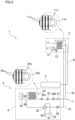
- the air conditioner 1 includes an indoor unit 2 attached to a wall surface, etc. of a room and an outdoor unit 3 installed outside the room.
- the outdoor unit 3 includes an outdoor refrigerant unit 4 and a humidification unit 5.
- the indoor unit 2 is connected to the outdoor refrigerant unit 4 through a refrigerant pipe 7 so that a refrigerant circuit is formed.
- the indoor unit 2 is connected to the humidification unit 5 through an air supply duct 8 used for supplying heated air or humid air to the indoor unit 2. The heated air and the humid air are generated in the humidification unit 5.
- the outdoor refrigerant unit 4 includes: a compressor 21; a four-pass switching valve 22 which is connected to the discharging port of the compressor 21; an accumulator 23 which is connected to the sucking port of the compressor 21; an outdoor heat exchanger 24 connected to the four-pass switching valve 22; and an electric expansion valve 25 connected to the outdoor heat exchanger 24.
- the outdoor heat exchanger 24 is a cross-fin-tube-type heat exchanger panel which includes an outdoor piping section and plural fins 24c.
- the outdoor piping section is formed of: plural heat transfer tubes 24a; and a U-bend 24b which is a connecting pipe connecting end portions of the heat transfer tubes 24a to one another.
- each heat transfer tube 24a is a straight pipe.
- each heat transfer tube 24a may be a hairpin tube including two straight pipe portions and a U-shaped portion connecting these two straight pipe portions.
- Each fin 24c is a flat-plate member, and penetrated by the heat transfer tubes 24a. Each fin 24c is in contact with outer circumferential surfaces of the heat transfer tubes 24a.
- Each heat transfer tube 24a (see FIG. 4A ) is formed of: a base material 34 made of aluminum or aluminum alloy; and a sacrificial layer 35 made of zinc or alloy including zinc. The sacrificial layer 35 is formed on an outer circumferential surface of the base material 34.
- Each fin 24c is made of aluminum or aluminum alloy, and a later-described coating is formed on its surface.
- the electric expansion valve 25 is connected to the outdoor heat exchanger 24 through a filter 26a, connected to a communication pipe 32 through a filter 26b and a liquid stop valve 27, and connected to one end of an indoor heat exchanger 11 through this communication pipe 32.
- the four-pass switching valve 22 is connected to a communication pipe 31 through a gas stop valve 28, and connected to the other end of the indoor heat exchanger 11 through this communication pipe 31.
- Each of these communication pipes 31 and 32 is equivalent to the refrigerant pipe 7 shown in FIG. 1 and FIG. 2 .
- an outdoor fan 29 is provided for discharging air having been subjected to heat exchange in the outdoor heat exchanger 24 to the outside.
- the outdoor fan 29 is a propeller fan which is rotationally driven by an outdoor fan motor 30.
- the heat exchange occurs between (i) a refrigerant flowing in each heat transfer tube 24a through the compressor 21 or the electric expansion valve 25 and (ii) air making contact with each heat transfer tube 24a and each fin 24c.
- the indoor heat exchanger 11 connected to the communication pipes 31 and 32 is provided in the indoor unit 2.
- the indoor heat exchanger 11 is a cross-fin-tube-type heat exchanger panel which includes an indoor piping section and plural fins 11c.
- the indoor piping section is formed of: plural heat transfer tubes 11a; and a U-bend 11b which is a connecting pipe connecting end portions of the heat transfer tubes 11a to one another.
- each heat transfer tube 11a is a straight pipe.
- each heat transfer tube 11a may be a hairpin tube including two straight pipe portions and a U-shaped portion connecting these two straight pipe portions.
- Each fin 11c is a flat-plate member, and penetrated by the heat transfer tubes 11a.
- Each fin 11c is in contact with outer circumferential surfaces of the heat transfer tubes 11a.
- Each heat transfer tube 11a (see FIGs. 4B and 4C ) is formed of: a base material 44a or 44b made of aluminum or aluminum alloy; and a sacrificial layer 45a or 45b made of zinc or alloy including zinc. Each of the sacrificial layer 45a and 45b is formed on an outer circumferential surface of the base material 44a or 44b.
- Each fin 11c is made of aluminum or aluminum alloy, and a later-described coating is formed on its surface.
- the heat exchange occurs between (i) a refrigerant which is supplied from the outdoor refrigerant unit 4 through the refrigerant pipe 7 and which flows in each heat transfer tube 11a and (ii) air making contact with each heat transfer tube 11a and each fin 11c.
- the indoor fan 12 is a cross-flow fan which is cylindrical in shape and on a circumferential surface of which a large number of blades are provided.
- the indoor fan 12 is configured to generate an air flow in a direction intersecting with its rotational axis.
- the indoor fan 12 is configured to allow room air to be sucked into the indoor unit 2 from a main air inlet 6a and an auxiliary air inlet 6b and to blow out, from an outlet 9, air having exchanged heat with the refrigerant flowing in each heat transfer tube 11a of the indoor heat exchanger 11.
- the indoor heat exchanger 11 is divided into four parts shown in FIG. 3 , i.e., a front-surface upper part Ba, a front-surface intermediate part Bb, a front-surface lower part Bc, and a back-surface part Bd. These four parts Ba, Bb, Bc, and Bd are connected to one another by a connecting pipe through which the refrigerant passes.
- a front-surface upper part Ba is close to an upper end portion of the back-surface part Bd
- the front-surface upper part Ba is positioned so that its lower end portion is provided in front of its upper end portion
- the back-surface part Bd is positioned so that its lower end portion is provided behind its upper end portion.
- the indoor heat exchanger 11 is inverse V-shaped in a side view.
- the front-surface intermediate part Bb vertically extends, and the front-surface lower part Bc is inclined so that its lower end portion is provided behind its upper end portion.
- plural straight pipes equivalent to heat transfer tubes are provided to form two lines in each of the four parts Ba, Bb, Bc, and Bd.
- the two lines each formed of the straight pipes are located on the upstream and downstream of the airflow, respectively, to the indoor fan 12.
- the up-down direction and front-rear direction of the indoor unit 2 are defined as those shown in FIG. 3 .
- the humidification unit 5 is provided on the outdoor refrigerant unit 4.
- the humidification unit 5 includes a moisture-absorbing rotor, a heater assembly, a humiliation fan, and an absorption fan (all of those are not shown).
- the humidification unit 5 is configured to take in outdoor air and to generate the heated air or humid air.
- the generated heated air or humid air is supplied to the indoor unit 2 through the air supply duct 8.
- a part of salt such as a chlorine compound and a chlorine ion included in the outdoor air is removed from the air by a heating process or a humidifying process of the humidification unit 5.
- the air supply duct 8 extends horizontally between a front panel 10 and the front-surface upper part Ba of the indoor heat exchanger 11 in the indoor unit 2.
- An opening 8a which is an outlet of the air supply duct 8 is provided in the indoor unit 2 so as to face the front-surface upper part Ba of the indoor heat exchanger 11.
- the heated air or humid air supplied from the humidification unit 5 is blown out from the opening 8a into the indoor unit 2, and then blown out from the outlet 9 into a room by the indoor fan 12 along with the room air sucked from the main air inlet 6a and the auxiliary air inlet 6b.
- the length of the air supply duct 8 and the opening 8a in a width direction (a direction orthogonal to the plane of FIG. 3 ) of the indoor unit 2 is smaller than that of the indoor heat exchanger 11 in the width direction.
- the former length is 1/3 to 1/4 of the latter length. Therefore, only a part of the front-surface upper part Ba in the width direction faces the opening 8a of the air supply duct 8, and the remaining part of the front-surface upper part Ba in the width direction does not face the opening 8a of the air supply duct 8.
- the salt content of the heated air or humid air blown out from the opening 8a of the air supply duct 8 is lower than that of the outdoor air and higher than that of the room air.
- the heat transfer tubes 11a of the indoor heat exchanger 11 are divided into two groups depending on the thickness of a sacrificial layer formed on the outer circumferential surface of each heat transfer tube 11a.
- the first group is formed of heat transfer tubes 11a1 included in the front-surface intermediate part Bb, the front-surface lower part Bc, and the back-surface part Bd.
- the second group is formed of heat transfer tubes 11a2 included in the front-surface upper part Ba.
- the heat transfer tubes 11a2 of the second group are closer to the opening 8a of the air supply duct 8 than the heat transfer tubes 11a1 of the first group are to the opening 8a.
- each heat transfer tube is close to the opening 8a of the air supply duct 8 is determined by comparing parts of heat transfer tubes with one another.
- a part of each transfer tube (a part of each heat transfer tube, which overlaps the opening 8a in the width direction (i.e., a longitudinal direction of each heat transfer tube) of the indoor unit 2 of the present embodiment) is closer to the opening 8a than the remaining part of each heat transfer tube is to the opening 8a.
- the thickness of a sacrificial layer formed on an outer circumferential surface of each heat transfer tube 11a2 of the second group is larger than that of a sacrificial layer formed on an outer circumferential surface of each heat transfer tube 11a1 of the first group.
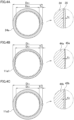
- each heat transfer tube 24a of the outdoor heat exchanger 24 is a cylindrical tube with an outer diameter Do1 and an inner diameter Do2.
- an inner circumferential surface of the heat transfer tube 24a is an uneven surface on which ribs extend along the longitudinal direction of the heat transfer tube 24a.
- the heat transfer tube 24a is formed of: the base material 34 made of aluminum or aluminum alloy; and the sacrificial layer 35 which is made of zinc or alloy including zinc and which is formed on the outer circumferential surface of the base material 34.
- the electric potential of metal forming the sacrificial layer 35 is lower than that of metal forming the base material 34.
- the sacrificial layer 35 and the base material 34 are diffusion bonded. That is, the heat transfer tube 24a is formed of a clad material.
- the sacrificial layer 35 is formed over the entire length of the heat transfer tube 24a.
- the thickness to of the sacrificial layer 35 is substantially uniform throughout the circumference of the base material 34. With this arrangement, the thickness to is the maximum thickness of the sacrificial layer 35.
- the thickness to of the sacrificial layer 35 is preferably 0.04 mm or more.
- thickness to of the sacrificial layer 35 is 0.05 mm.
- each heat transfer tube 11a1 of the first group of the indoor heat exchanger 11 is a cylindrical tube with an outer diameter Di1 and an inner diameter Di2.
- An inner circumferential surface of the heat transfer tube 11a1 is an uneven surface in the same manner as shown in an example of FIG. 4A .
- the heat transfer tube 11a1 is formed of: the base material 44a made of aluminum or aluminum alloy; and the sacrificial layer 45a which is made of zinc or alloy including zinc and which is formed on the outer circumferential surface of the base material 44a.
- the electric potential of metal forming the sacrificial layer 45a is lower than that of metal forming the base material 44a.
- the sacrificial layer 45a and the base material 44a are diffusion bonded. That is, the heat transfer tube 11a1 is formed of a clad material. The sacrificial layer 45a is formed over the entire length of the heat transfer tube 11a1.
- the thickness ti1 of the sacrificial layer 45a is substantially uniform throughout the circumference of the base material 44a. With this arrangement, the thickness ti1 is the maximum thickness of the sacrificial layer 45a.
- the outer diameter Di1 of the heat transfer tube 11a1 is 5 mm to 7 mm
- the thickness ti1 of the sacrificial layer 45a is preferably 0.01 mm or more. For example, thickness ti1 of the sacrificial layer 45a is 0.03 mm.
- each heat transfer tube 11a2 of the second group of the indoor heat exchanger 11 is a cylindrical tube with an outer diameter Di3 and an inner diameter Di4.
- An inner circumferential surface of the heat transfer tube 11a2 is an uneven surface in the same manner as shown in the example of FIG. 4A .
- the heat transfer tube 11a2 is formed of: the base material 44b made of aluminum or aluminum alloy; and the sacrificial layer 45b which is made of zinc or alloy including zinc and which is formed on the outer circumferential surface of the base material 44b.
- the electric potential of metal forming the sacrificial layer 45b is lower than that of metal forming the base material 44b.
- the sacrificial layer 45b and the base material 44b are diffusion bonded. That is, the heat transfer tube 11a2 is formed of a clad material. The sacrificial layer 45b is formed over the entire length of the heat transfer tube 11a2.
- the thickness ti2 of the sacrificial layer 45b is substantially uniform throughout the circumference of the base material 44b. With this arrangement, the thickness ti2 is the maximum thickness of the sacrificial layer 45b.
- the outer diameter Di3 of the heat transfer tube 11a2 is 5 mm to 7 mm
- the thickness ti2 of the sacrificial layer 45b is preferably 0.02 mm or more. For example, thickness ti2 of the sacrificial layer 45b is 0.04 mm.
- the thickness to of the sacrificial layer 35 of the outdoor heat exchanger 24 is larger than the thickness ti2 of the sacrificial layer 45b of the second group of the indoor heat exchanger 11, and the thickness ti2 of the sacrificial layer 45b is larger than the thickness ti1 of the sacrificial layer 45a of the first group of the indoor heat exchanger 11. That is, the sacrificial layer 35, the sacrificial layer 45b, and the sacrificial layer 45a in this order are the largest, the second largest, and the third largest in maximum thickness (to>ti2>ti1).
- each of the sacrificial layers 35, 45a, and 45b can be measured with use of an electron probe micro analyzer (EPMA), etc.
- EPMA electron probe micro analyzer
- each of the heat transfer tubes 24a, 11a1, and 11a2 is cut not at around its end portion to which the U-bend 24b or 11b is brazed but at around its center in the longitudinal direction.
- the inner diameter Di2 of the heat transfer tube 11a1 is larger than each of the inner diameter Do2 of the heat transfer tube 24a of the outdoor heat exchanger 24 and the inner diameter Di4 of the heat transfer tube 11a2 (Do2, Di4 ⁇ Di2).
- the wall thickness Ti1 of the heat transfer tube 11a1 is smaller than each of the wall thickness To of the heat transfer tube 24a of the outdoor heat exchanger 24 and the wall thickness Ti2 of the heat transfer tube 11a2 (Ti1 ⁇ To, Ti2).
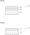
- each fin 24c of the outdoor heat exchanger is formed of a base material 52 which is made of aluminum or aluminum alloy and on a surface of which coatings are formed.
- a hydrophobic coating 53 and a hydrophilic coating 54 which are made of urethane resin are formed in this order on the base material 52. These coatings are formed by a dipping process. Both the hydrophobic coating 53 and the hydrophilic coating 54 improve the corrosion resistance of the fin 24c.
- the hydrophilic coating 54 facilitates the drainage of a drain adhering to the fin 24c.
- each fin 11c of the indoor heat exchanger is formed of a base material 56 which is made of aluminum or aluminum alloy and on a surface of which a coating is formed.
- a hydrophilic coating 57 is formed on the base material 56.
- the hydrophilic coating 57 is formed by the dipping process.
- the hydrophilic coating 57 improves the corrosion resistance of the fin 11c, and facilitates the drainage of a drain adhering to the fin 11c.
- the thickness of a combination of the hydrophobic coating 53 and hydrophilic coating 54 of the fin 24c is larger than that of the hydrophilic coating 57 of the fin 11c.
- the electric potential of zinc or alloy including zinc forming the sacrificial layers 35, 45a, and 45b is lower than that of aluminum or aluminum alloy forming the base materials 34, 44a, and 44b. Because of this, the corrosion of the base materials 34, 44a, and 44b does not begin yet, and the corrosion of the sacrificial layers 35, 45a, and 45b further progresses so that the sacrificial layers 35, 45a, and 45b on the base materials 34, 44a, and 44b no longer exist.
- pitting corrosion of the base materials 34, 44a, and 44b begins in each of the following cases: the case where electric potential is constant on each of the surfaces of the sacrificial layers 35, 45a, and 45b; and the case where electric potential is not constant on each of the surfaces of the sacrificial layers 35, 45a, and 45b.
- the pitting corrosion is a phenomenon in which the corrosion progresses typically in a thickness direction of a material.
- the thickness to of the sacrificial layer 35 formed on the outer circumferential surface of the heat transfer tube 24a of the outdoor heat exchanger 24 is larger than the thickness ti1 of the sacrificial layer 45a formed on the outer circumferential surface of the heat transfer tube 11a1 of the indoor heat exchanger 11.
- the corrosion is suppressed at the following tubes: the heat transfer tube 11a1 of the indoor heat exchanger 11 in which a refrigerant exchanging heat with the room air flows; and the heat transfer tube 24a of the outdoor heat exchanger 24 in which a refrigerant exchanging heat with the outdoor air flows.
- the salt content of the room air is low, and the salt content of the outdoor air is high.
- the sacrificial layer 45a does not need to be thick, an amount of use of materials is reduced. As a result, low cost is achieved.
- the thickness ti2 of the sacrificial layer 45b formed on the outer circumferential surface of the heat transfer tube 11a2 of the second group of the indoor heat exchanger 11 is larger than the thickness ti1 of the sacrificial layer 45a formed on the outer circumferential surface of the heat transfer tube 11a1 of the first group of the indoor heat exchanger 11.
- the salt content of the room air is low, and the salt content of each of the heated air and the humid air is lower than that of the outdoor air and higher than that of the room air.
- the sacrificial layer 45a does not need to be thick, an amount of use of materials is reduced. As a result, the low cost is achieved.
- the thickness ti2 of the sacrificial layer 45b is smaller than the thickness to of the sacrificial layer 35, an amount of use of materials is reduced. As a result, the low cost is achieved.
- the thickness ti1 of the sacrificial layer 45a of the indoor heat exchanger 11 is relatively small so that the ratio of thickness of the base material 44a to that of the sacrificial layer 45a is large in the heat transfer tube 11a1. This makes it easy to maintain the outer diameter Di1 of the heat transfer tube 11a1 and to suppress the decrease of the inner diameter Di2 of the heat transfer tube 11a1. By suppressing the decrease of the inner diameter Di2 of the heat transfer tube 11a1, (i) the increase in pressure drop of a refrigerant passing through the heat transfer tube 11a1 of the indoor heat exchanger 11 and (ii) the decrease in capacity of the indoor heat exchanger 11 are suppressed.
- the thickness ti1 of the sacrificial layer 45a of the indoor heat exchanger 11 is relatively small so that the ratio of thickness of the base material 44a to that of the sacrificial layer 45a is large in the heat transfer tube 11a1.
- This makes it possible to maintain the inner diameter Di2 of the heat transfer tube 11a1 and to suppress the increase of the outer diameter Di1 of the heat transfer tube 11a1.
- the structure of the fin 11c does not need to be greatly changed and (ii) air resistance is not increased in the indoor heat exchanger 11.
- the thickness ti1 of the sacrificial layer 45a is smaller than each of the thickness to of the sacrificial layer 35 and the thickness ti2 of the sacrificial layer 45b as described above.
- the necessary thickness of the base material 44a is secured, and the wall thickness Ti1 of the heat transfer tube 11a1 which is a combination of the sacrificial layer 45a and the base material 44a is smaller than each of the wall thickness To of the heat transfer tube 24a and the wall thickness Ti2 of the heat transfer tube 11a2. This improves the efficiency of heat conduction in the heat transfer tube 11a1 of the indoor heat exchanger 11.
- the inner diameter Di2 of the heat transfer tube 11a1 of the first group of the indoor heat exchanger 11 is larger the inner diameter Do2 of the heat transfer tube 24a of the outdoor heat exchanger 24. This reduces the pressure drop of a refrigerant in the indoor heat exchanger 11. Furthermore, this makes the surface area of the inner circumferential surface of the heat transfer tube 11a1 relatively large. It is therefore possible to suppress the decrease in capacity of the indoor heat exchanger 11.
- the inner diameter Di2 of the heat transfer tube 11a1 of the first group of the indoor heat exchanger 11 is larger than the inner diameter Di4 of the heat transfer tube 11a2 of the second group of the indoor heat exchanger 11.
- these sacrificial layers 35, 45b, and 45a in this order are the largest, the second largest, and the third largest in thickness (to>ti2>ti1).
- This order reflects the salt content of air passing through the surface of each sacrificial layer. That is, because the outdoor air whose salt content is high passes through the surface of the sacrificial layer 35, the sacrificial layer 35 is thickest. Furthermore, because the outdoor air whose salt content is low passes through the surface of the sacrificial layer 45a, the sacrificial layer 45a is thinnest.
- the sacrificial layer 45b is thinner than the sacrificial layer 35 and thicker than the sacrificial layer 45a.
- the thicknesses of the sacrificial layers 35, 45a, and 45b of three types are adjusted as described above. This suppresses the occurrence of a large difference between the heat transfer tubes 11a1, 11a2, and 24a of three types in terms of a period of time from the initial state to a state in which a through hole is formed.
- each of the sacrificial layers 35, 45a, and 45b is made of zinc or alloy including zinc, and each of the base materials is made of aluminum or aluminum alloy.
- the electric potential of each of zinc and alloy including zinc is lower than that of each of aluminum and aluminum alloy.
- Each sacrificial layer may be made of metal which is neither zinc nor alloy including zinc, as long as the electric potential of the metal is lower than that of each of aluminum and aluminum alloy making a base material.
- the heat transfer tube 24a of the outdoor heat exchanger 24 and the heat transfer tube 11a of the indoor heat exchanger 11 are formed of clad materials in which the base materials 34, 44a, and 44b and the sacrificial layers 35, 45a, and 45b are diffusion bonded. This suppresses the thickness variation of each of the sacrificial layers 35, 45a, and 45b.
- an exposed part of the outer circumferential surface of each of the base materials 34, 44a, and 44b may be so far from the remaining part of each of the sacrificial layers 35, 45a, and 45b that the exposed part of the outer circumferential surface of each of the base materials 34, 44a, and 44b has a position where the anti-corrosion effect is not expected.
- the clad materials By using the clad materials, occurrence of this problem is suppressed.
- coatings are formed on the fin 24c of the outdoor heat exchanger 24 and the fin 11c of the outdoor heat exchanger 11.
- the fin 24c has the corrosion resistance.
- the thickness of a combination of the hydrophobic coating 53 and hydrophilic coating 54 of the fin 24c is larger than that of the hydrophilic coating 57 of the fin 11c. This improves the corrosion resistance of the fin 24c with which the outdoor air makes contact. In this regard, this improvement does not depend on the number of coatings formed on the fin 24c and the fin 11c.
- the number of coatings formed on the fin 24c may be smaller than or the same as that of coatings formed on the fin 11c.
- each heat transfer tube of an outdoor heat exchanger 24 is the same as that in First Embodiment.
- the structure of each heat transfer tube of an indoor heat exchanger is different from that in First Embodiment.
- the following will mainly describe how the structure of each heat transfer tube of the indoor heat exchanger is different from that in First Embodiment.
- the structure of an air supply duct 8 is the same as that in First Embodiment, and heat transfer tubes of the indoor heat exchanger are divided into two groups, i.e., (i) heat transfer tubes (those will be denoted by a reference symbol 61a1 in the present embodiment) of a first group and (ii) heat transfer tubes (those will be denoted by a reference symbol 61a2 in the present embodiment) of a second group which are closer to an opening 8a of the air supply duct 8 than the heat transfer tubes 61a1 of the first group are to the opening 8a.
- the first group includes heat transfer tubes included in a front-surface intermediate part Bb, a front-surface lower part Bc, and a back-surface part Bd as shown in FIG. 3 .
- the second group includes heat transfer tubes included in a front-surface upper part Ba. As described below, the thickness of a sacrificial layer formed on an outer circumferential surface of each heat transfer tube 61a2 of the second group is larger than that of a sacrificial layer formed on an outer circumferential surface of each heat transfer tube 61a1 of the first group.
- each heat transfer tube 61a1 of the first group of the indoor heat exchanger is a cylindrical tube with an outer diameter Di5 and an inner diameter Di6.
- the heat transfer tube 61a1 is formed of: a base material 74a made of aluminum or aluminum alloy; and a sacrificial layer 75a which is made of zinc or alloy including zinc and which is formed on an outer circumferential surface of the base material 74a.
- the heat transfer tube 61a1 is formed of a clad material.
- the thickness ti3 of the sacrificial layer 75a is substantially uniform throughout the circumference of the base material 74a. With this arrangement, the thickness ti3 is the maximum thickness of the sacrificial layer 75a.
- the outer diameter Di5 of the heat transfer tube 61a1 is 4 mm to 6 mm
- the thickness ti3 of the sacrificial layer 75a is preferably 0.01 mm or more.
- thickness ti3 of the sacrificial layer 75a is 0.03 mm.
- a sacrificial layer 35, the sacrificial layer 75b, and the sacrificial layer 75a in this order are the largest, the second largest, and the third largest in maximum thickness (to>ti4>ti3).
- the outer diameter Di5 of the heat transfer tube 61a1 is smaller than each of the outer diameter Do1 of the heat transfer tube 24a and the outer diameter Di7 of the heat transfer tube 61a2 (Di5 ⁇ Do1, Di7).
- the wall thickness Ti3 of the heat transfer tube 61a1 is smaller than each of the wall thickness To of the heat transfer tube 24a of the outdoor heat exchanger 24 and the wall thickness Ti4 of the heat transfer tube 61a2 (Ti3 ⁇ To, Ti4).
- the thickness to of the sacrificial layer 35 formed on an outer circumferential surface of the heat transfer tube 24a of the outdoor heat exchanger 24 is larger than the thickness ti3 of the sacrificial layer 75a formed on the outer circumferential surface of the heat transfer tube 61a1 of the indoor heat exchanger.
- the sacrificial layer 75a does not need to be thick, an amount of use of materials is reduced. As a result, low cost is achieved.
- the thickness ti4 of the sacrificial layer 75b is larger than the thickness ti3 of the sacrificial layer 75a. With this arrangement, the corrosion is suppressed at the heat transfer tubes 61a1 and 61a2.
- the thickness ti3 of the sacrificial layer 75a is smaller than each of the thickness to of the sacrificial layer 35 and the thickness ti4 of the sacrificial layer 75b as described above.
- the necessary thickness of the base material 74a is secured, and the wall thickness Ti3 of the heat transfer tube 61a1 which is a combination of the sacrificial layer 75a and the base material 74a is smaller than each of the wall thickness To of the heat transfer tube 24a and the wall thickness Ti4 of the heat transfer tube 61a2. This improves the efficiency of heat conduction in the heat transfer tube 61a1 of the indoor heat exchanger.
- the outer diameter Di5 of the heat transfer tube 61a1 of the first group is smaller than each of the outer diameter Do1 of the heat transfer tube 24a of the outdoor heat exchanger 24 and the outer diameter Di7 of the heat transfer tube 61a2 of the second group. This suppresses the increase in resistance of air passing through the indoor heat exchanger.
- each heat transfer tube of an outdoor heat exchanger 24 is the same as that in First Embodiment.
- the structure of each heat transfer tube of an indoor heat exchanger is different from that in First Embodiment.
- the following will mainly describe how the structure of each heat transfer tube of the indoor heat exchanger is different from that in First Embodiment.
- the structure of an air supply duct 8 is the same as that in First Embodiment, and heat transfer tubes of the indoor heat exchanger are divided into two groups, i.e., (i) heat transfer tubes (those will be denoted by a reference symbol 81a1 in the present embodiment) of a first group and (ii) heat transfer tubes (those will be denoted by a reference symbol 81a2 in the present embodiment) of a second group which are closer to an opening 8a of the air supply duct 8 than the heat transfer tubes 81a1 of the first group are to the opening 8a.
- the first group includes heat transfer tubes included in a front-surface intermediate part Bb, a front-surface lower part Bc, and a back-surface part Bd as shown in FIG. 3 .
- the second group includes heat transfer tubes included in a front-surface upper part Ba. As described below, the thickness of a sacrificial layer formed on an outer circumferential surface of each heat transfer tube 81a2 of the second group is larger than that of a sacrificial layer formed on an outer circumferential surface of each heat transfer tube 81a1 of the first group.
- each heat transfer tube 81a1 of the first group of the indoor heat exchanger is a cylindrical tube with an outer diameter Di9 and an inner diameter Di10.
- the heat transfer tube 81a1 is formed of: a base material 94a made of aluminum or aluminum alloy; and a sacrificial layer 95a which is made of zinc or alloy including zinc and which is formed on an outer circumferential surface of the base material 94a.
- the heat transfer tube 81a1 is formed of a clad material.
- the thickness ti5 of the sacrificial layer 95a is substantially uniform throughout the circumference of the base material 94a. With this arrangement, the thickness ti5 is the maximum thickness of the sacrificial layer 95a.
- the outer diameter Di9 of the heat transfer tube 81a1 is 3 mm to 5 mm
- the thickness ti5 of the sacrificial layer 95a is preferably 0.01 mm or more.
- thickness ti5 of the sacrificial layer 95a is 0.03 mm.
- each heat transfer tube 81a2 of the second group of the indoor heat exchanger is a cylindrical tube with an outer diameter Di11 and an inner diameter Di12.
- the heat transfer tube 81a2 is formed of: a base material 94b made of aluminum or aluminum alloy; and a sacrificial layer 95b which is made of zinc or alloy including zinc and which is formed on an outer circumferential surface of the base material 94b.
- the heat transfer tube 81a2 is formed of a clad material.
- the thickness ti6 of the sacrificial layer 95b is substantially uniform throughout the circumference of the base material 94b. With this arrangement, the thickness ti6 is the maximum thickness of the sacrificial layer 95b.
- the outer diameter Di11 of the heat transfer tube 81a2 is 3 mm to 5 mm
- the thickness ti6 of the sacrificial layer 95b is preferably 0.02 mm or more.
- thickness ti6 of the sacrificial layer 95b is 0.04 mm.
- a sacrificial layer 35, the sacrificial layer 95b, and the sacrificial layer 95a in this order are the largest, the second largest, and the third largest in maximum thickness (to>ti6>ti5).
- Each of the outer diameter Di9 of the heat transfer tube 81a1 and the outer diameter Di11 of the heat transfer tube 81a2 is smaller than an outer diameter Do1 of each heat transfer tube 24a of the outdoor heat exchanger 24 (Di9, Di11 ⁇ Do1).
- Each of the inner diameter Di10 of the heat transfer tube 81a1 and the inner diameter Di12 of the heat transfer tube 81a2 is smaller than an inner diameter Do2 of the heat transfer tube 24a of the outdoor heat exchanger 24 (Di10, Di12 ⁇ Do2).
- Each of the wall thickness Ti5 of the heat transfer tube 81a1 and the wall thickness Ti6 of the heat transfer tube 81a2 is smaller than the wall thickness To of the heat transfer tube 24a (Ti5, Ti6 ⁇ To).
- the thickness to of the sacrificial layer 35 formed on an outer circumferential surface of the heat transfer tube 24a of the outdoor heat exchanger 24 is larger than the thickness ti5 of the sacrificial layer 95a formed on the outer circumferential surface of the heat transfer tube 81a1 of the indoor heat exchanger.
- the sacrificial layer 95a does not need to be thick, an amount of use of materials is reduced. As a result, low cost is achieved.
- the thickness ti6 of the sacrificial layer 95b is larger than the thickness ti5 of the sacrificial layer 95a. With this arrangement, the corrosion is suppressed at the heat transfer tubes 81a1 and 81a2.
- each of the thickness ti5 of the sacrificial layer 95a and the thickness ti6 of the sacrificial layer 95b is smaller than the thickness to of the sacrificial layer 35 as described above.
- the necessary thicknesses of the base materials 94a and 94b are secured, and each of the following wall thicknesses is smaller than the wall thickness To of the heat transfer tube 24a: the wall thickness Ti5 of the heat transfer tube 81a1 which is a combination of the sacrificial layer 95a and the base material 94a; and the wall thickness Ti6 of the heat transfer tube 81a2 which is a combination of the sacrificial layer 95b and the base material 94b.
- each of the outer diameter Di5 of the heat transfer tube 61a1 the first group and the outer diameter Di7 of the heat transfer tube 61a2 of the second group is smaller the outer diameter Do1 of the heat transfer tube 24a of the outdoor heat exchanger 24. This suppresses the increase in resistance of air passing through the indoor heat exchanger as compared to Second Embodiment.
- An outdoor unit 3 of an air conditioner of the present embodiment does not include a humidification unit 5 shown in FIG. 2 .
- An air supply duct 8 is configured to supply the inhaled outdoor air directly to an indoor unit 2. With this arrangement, the salt content of air blown out from an opening 8a of the air supply duct 8 is the same as that of the outdoor air.
- the air conditioner of the present embodiment is different from that of First Embodiment in terms of the thickness of a sacrificial layer formed on an outer circumferential surface of each heat transfer tube of a second group. The following will mainly describe this difference.
- the outdoor unit 3 may include a unit instead of the humidification unit 5 and this unit may take in the outdoor air and supply the outdoor air to the indoor unit 2 through the air supply duct 8 without reducing the salt content of the outdoor air.
- each heat transfer tube of an outdoor heat exchanger is the same as that in First Embodiment shown in FIG. 4A .
- Each heat transfer tube of a first group of an indoor heat exchanger is the same as that in First Embodiment shown in FIG. 4B .
- each heat transfer tube 101a2 of the second group of the indoor heat exchanger is a cylindrical tube with an outer diameter Di13 and an inner diameter Di14.
- the heat transfer tube 101a2 is formed of: a base material 114b made of aluminum or aluminum alloy; and a sacrificial layer 115b which is made of zinc or alloy including zinc and which is formed on an outer circumferential surface of the base material 114b.
- the heat transfer tube 101a2 is formed of a clad material.
- the thickness ti7 of the sacrificial layer 115b is substantially uniform throughout the circumference of the base material 114b. With this arrangement, the thickness ti7 is the maximum thickness of the sacrificial layer 115b.
- the outer diameter Di13 of the heat transfer tube 61a2 is 5 mm to 7 mm
- the thickness ti7 of the sacrificial layer 115b is preferably 0.04 mm or more.
- thickness ti7 of the sacrificial layer 115b is 0.05 mm.
- the thickness to of the sacrificial layer 35 of the outdoor heat exchanger 24 is the same as the thickness ti7 of the sacrificial layer 115b of the second group of the indoor heat exchanger.
- the thickness ti7 of the sacrificial layer 115b of the second group is the same as the thickness to of the sacrificial layer 35 of the outdoor heat exchanger 24 as described above. With this arrangement, corrosion is suppressed at the heat transfer tube 101a2 of the second group to the same degree as at the heat transfer tube 24a of the outdoor heat exchanger 24.
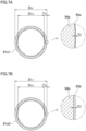
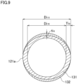
- FIG. 9 is a schematic diagram which illustrates the thickness of each sacrificial layer with a size larger than an actual size.
- the structure of each heat transfer tube of an outdoor heat exchanger 24 is the same as that in First Embodiment.
- the structure of each heat transfer tube of an indoor heat exchanger is different from that in First Embodiment.
- the following will mainly describe how the structure of each heat transfer tube of the indoor heat exchanger is different from that in First Embodiment.
- an air supply duct is not provided, and heat transfer tubes of the indoor heat exchanger are not divided into groups depending on the thickness of each sacrificial layer.
- each heat transfer tube 121a of the indoor heat exchanger of the present embodiment is a cylindrical tube with an outer diameter Di15 and an inner diameter Di16.
- An inner circumferential surface of the heat transfer tube 121a is not an uneven surface on which ribs extend along a longitudinal direction thereof.
- the cross section of this inner circumferential surface is circular in shape.
- the heat transfer tube 121a is formed of: a base material 131 made of aluminum or aluminum alloy; and a sacrificial layer 132 which is made of aluminum-zinc alloy and which is formed on an outer circumferential surface of the base material 131.
- each heat transfer tube is formed of a clad material in which a base material and a sacrificial layer are diffusion bonded.
- the sacrificial layer 132 is a diffuse layer which is made of aluminum-zinc alloy by spraying zinc on the base material 131.
- zinc is used as metal the electric potential of which is lower than that of aluminum.
- the thickness of a sacrificial layer actually formed tends to vary in a circumferential direction of a base material.
- the maximum thickness ti8 of the sacrificial layer 132 is provided at two points on the outer circumferential surface of the base material 131 which are 180 degrees away from each other. The thickness of the sacrificial layer 132 decreases away from these two points.
- the thickness of the sacrificial layer varies in the circumferential direction of the base material the larger the maximum thickness of the sacrificial layer is, the further corrosion is suppressed. This is understood by the progress of corrosion described in First Embodiment.
- the outer diameter Di15 of the heat transfer tube 121a is 4 mm to 6 mm
- the thickness ti8 of the sacrificial layer 132 is preferably 0.12 mm or more.
- thickness ti8 of the sacrificial layer 132 is 0.12 mm.
- the maximum thickness ti8 of the sacrificial layer 132 formed on the outer circumferential surface of the heat transfer tube 121a of the indoor heat exchanger is smaller than the maximum thickness to of a sacrificial layer 35 formed on an outer circumferential surface of each heat transfer tube 24a of the outdoor heat exchanger 2.
- the sacrificial layer formed on the outer circumferential surface of the heat transfer tube of the outdoor heat exchanger 2 may be formed by spraying.
- the maximum thickness of the sacrificial layer formed on the outer circumferential surface of the heat transfer tube of the outdoor heat exchanger is preferably 0.17 mm or more.
- the sacrificial layer 132 is relatively easily formed by spraying zinc on the base material 131. Effects which are the same as those of the heat transfer tube 11a1 of First Embodiment described above are obtained.
- the heat transfer tubes of the first group or second group belong to each of the four parts (the front-surface upper part Ba, the front-surface intermediate part Bb, the front-surface lower part Bc, and the back-surface part Bd) of the indoor heat exchanger 11. That is, heat transfer tubes of two types between which the thickness of a sacrificial layer is different are not included in the same part.
- the heat transfer tubes of the two types between which the thickness of the sacrificial layer is different may be included in each of the four parts by using the heat transfer tubes of the second group as heat transfer tubes on one line which is closer to the opening 8a of the air supply duct 8 and using the heat transfer tubes of the first group as heat transfer tubes on the other line which is further from the opening 8a than the heat transfer tubes of the second group.
- the thickness of the sacrificial layer of each heat transfer tube of the second group is large while that of the first group is small.
- each heat transfer tube may be suitably changed.
- the outer diameter and inner diameter of the heat transfer tube 24a (see FIG. 4A ) of the outdoor heat exchanger 24 may be the same as those of each heat transfer tube (see FIG. 4B ) of the first group, those of the heat transfer tube 61a1 (see FIG. 6A ) of the first group of Second Embodiment, or those of the heat transfer tube 81a1 (see FIG. 7A ) of the first group of Third Embodiment.
- the outer diameter and inner diameter of the heat transfer tube 11a2 see FIG.
- the outer diameter and inner diameter of the heat transfer tube 61a2 (see FIG. 6B ) of the second group may be the same as those of the heat transfer tube 61a1 (see FIG. 6A ) of the first group or those of the heat transfer tube 11a1 (see FIG. 4B ) of the first group of First Embodiment.
- the inner diameter Di2 of the heat transfer tube 11a1 of the first group is larger than the inner diameter Do2 of the heat transfer tube 24a of the outdoor heat exchanger 24, and the outer diameter Di1 of the heat transfer tube 11a1 of the first group is the same as the outer diameter Do1 of the heat transfer tube 24a of the outdoor heat exchanger 24.
- the outer diameter Di5 of the heat transfer tube 61a1 of the first group is smaller than the outer diameter Do1 of the heat transfer tube 24a of the outdoor heat exchanger 24, and the inner diameter Di6 of the heat transfer tube 61a1 of the first group is the same as the inner diameter Do2 of the heat transfer tube 24a of the outdoor heat exchanger 24.
- each heat transfer tube of the first group may be larger than that of each heat transfer tube of the outdoor heat exchanger and (ii) the outer diameter of the heat transfer tube of the first group may be smaller than the outer diameter Do1 of the heat transfer tube of the outdoor heat exchanger.
- the inner diameter of the heat transfer tube of the first group may be larger than that of each heat transfer tube of the second group and (ii) the outer diameter of the heat transfer tube of the first group may be smaller than that of the heat transfer tube of the second group.
- the air conditioner of each of First to Fourth Embodiments described above includes the air supply duct configured to allow the outdoor air to flow toward the indoor unit.
- the air conditioner of each of these Embodiments may not include the air supply duct.
- all heat transfer tubes of the indoor heat exchanger may be the same as the heat transfer tubes of the first groups in each of these Embodiments described above.
- the humidification unit 5 includes the moisture-absorbing rotor, the heater assembly, the humiliation fan, and the absorption fan.
- the humidification unit 5 may be an air supply unit used for supplying the outdoor air to the room.
- the air supply unit includes an air supply fan.
- the humidification unit and the air supply unit may be provided on the refrigerant unit 4 or may be provided separately from the outdoor unit.
- the thickness of the sacrificial layer formed on each heat transfer tube of the first group of the indoor heat exchanger may be zero.
- the present disclosure is applicable to a microchannel heat exchanger including a heat transfer tube made of aluminum or aluminum alloy.
- the present disclosure is also applicable to an outdoor air processor configured to condition and supply outdoor air to a room.
- the air conditioner of the present disclosure is configured to condition air by connecting the following units to each other: the indoor unit including a first heat exchanger in which a refrigerant exchanging heat with the room air flows; the outdoor unit including a second heat exchanger in which a refrigerant exchanging heat with the outdoor air flows.
- the first heat exchanger includes a first heat transfer tube
- the second heat exchanger includes a second heat transfer tube.
- a coating is formed on a first fin in contact with an outer circumferential surface of the first heat transfer tube
- a coating is formed on a second fin in contact with an outer circumferential surface of the second heat transfer tube.
- a first sacrificial layer and a second sacrificial layer may not be formed on the first heat transfer tube and the second heat transfer tube.
- the thickness of the coating formed on the second fin is preferably larger than that of the coating formed on the first fin.
- the first fin and the second fin are preferably made of aluminum or aluminum alloy.
- the first sacrificial layer and the second sacrificial layer are preferably formed on the first heat transfer tube and the second heat transfer tube.
- the thickness of the sacrificial layer formed on the outer circumferential surface of the heat transfer tube of each heat exchanger may vary depending on a position in the heat exchanger.
- the thickness of one part of the sacrificial layer is preferably larger than that of another part of the sacrificial layer.
- the air speed is high at one part of the sacrificial layer and low at another part thereof. To an area where the air speed is high, the large number of chloride ions accelerating the corrosion adheres so that the corrosion easily progresses.
- the thickness of the sacrificial layer is therefore arranged to vary depending on the position in the heat exchanger as described above so that the corrosion of the heat transfer tube is suppressed in accordance with the distribution of air speed.
- This arrangement to vary the thickness of the sacrificial layer in accordance with the distribution of air speed is applicable to both of the indoor heat exchanger and the outdoor heat exchanger. Furthermore, this arrangement is applicable to a case where, in each of First to Fourth Embodiments, (i) the air supply duct 8 is not provided and (ii) only the heat transfer tube of the first group is formed in the indoor heat exchanger.
Landscapes
- Engineering & Computer Science (AREA)
- Mechanical Engineering (AREA)
- General Engineering & Computer Science (AREA)
- Physics & Mathematics (AREA)
- Thermal Sciences (AREA)
- Chemical & Material Sciences (AREA)
- Combustion & Propulsion (AREA)
- Heat-Exchange Devices With Radiators And Conduit Assemblies (AREA)
- Other Air-Conditioning Systems (AREA)
- Air Filters, Heat-Exchange Apparatuses, And Housings Of Air-Conditioning Units (AREA)
Claims (17)
- Klimaanlage (1), die so konfiguriert ist, dass sie Luft klimatisiert, indem sie eine Inneneinheit (2), die einen ersten Wärmetauscher (11) einschließt, in dem ein Kältemittel, das Wärme mit Raumluft austauscht, strömt, mit einer Außeneinheit (3) verbindet, die einen zweiten Wärmetauscher (24) einschließt, in dem ein Kältemittel, das Wärme mit Außenluft austauscht, strömt, wobei der erste Wärmetauscher (11) ein erstes Wärmeübertragungsrohr (11a1; 61a1; 81a1; 121a) aus Aluminium oder einer Aluminiumlegierung einschließt,wobei der zweite Wärmetauscher (24) ein zweites Wärmeübertragungsrohr (24a) aus Aluminium oder einer Aluminiumlegierung einschließt,wobei eine erste Opferschicht (45a; 75a; 95a; 132) auf einer äußeren Umfangsfläche des ersten Wärmeübertragungsrohrs (11a1; 61a1; 81a1; 121a) ausgebildet ist,wobei eine zweite Opferschicht (35) auf einer äußeren Umfangsfläche des zweiten Wärmeübertragungsrohrs (24a) ausgebildet ist, und dadurch gekennzeichnet, dass die maximale Dicke (to) der zweiten Opferschicht (35) größer ist als die maximale Dicke (ti1; ti3; ti5; ti8) der ersten Opferschicht (45a; 75a; 95a; 132).
- Klimaanlage nach Anspruch 1, wobei die Wanddicke (Ti1; Ti3; Ti5; Ti8) des ersten Wärmeübertragungsrohrs (11a1; 61a1; 81a1; 121a) kleiner ist als die Wanddicke (To) des zweiten Wärmeübertragungsrohrs (24a).
- Klimaanlage nach Anspruch 1 oder 2, wobei ein Innendurchmesser (Di2; Di16) des ersten Wärmeübertragungsrohrs (11a1; 121a) größer ist als ein Innendurchmesser (Do2) des zweiten Wärmeübertragungsrohrs (24a).
- Klimaanlage nach einem der Ansprüche 1 bis 3, wobei ein Außendurchmesser (Di5; Di9) des ersten Wärmeübertragungsrohrs (61a1; 81a1) kleiner ist als ein Außendurchmesser (Do1) des zweiten Wärmeübertragungsrohrs (24a).
- Klimaanlage nach einem der Ansprüche 1 bis 4, wobei die erste Opferschicht (45a; 75a; 95a; 132) und die zweite Opferschicht (35) aus Zink oder einer Zink einschließenden Legierung hergestellt sind.
- Klimaanlage nach einem der Ansprüche 1 bis 5, wobei die maximale Dicke (ti8) der ersten Opferschicht (132) 0,12 mm oder mehr beträgt.
- Klimaanlage nach einem der Ansprüche 1 bis 6, wobei die maximale Dicke der zweiten Opferschicht 0,17 mm oder mehr beträgt.
- Klimaanlage nach einem der Ansprüche 1 bis 7, wobei das erste Wärmeübertragungsrohr (11a1; 61a1; 81a1) gebildet ist aus: einem Basismaterial (34, 44a; 74a; 94a), das aus Aluminium oder einer Aluminiumlegierung hergestellt ist; und der ersten Opferschicht (45a; 75a; 95a), das zweite Wärmeübertragungsrohr (24a) gebildet ist aus: einem weiteren Basismaterial (34, 44a; 74a; 94a), das aus Aluminium oder einer Aluminiumlegierung hergestellt ist; und der zweiten Opferschicht (35), und sowohl das erste Wärmeübertragungsrohr als auch das zweite Wärmeübertragungsrohr aus einem plattierten Material gebildet ist.
- Klimaanlage nach einem der Ansprüche 1 bis 7, wobei das erste Wärmeübertragungsrohr (121a) gebildet ist aus: einem Basismaterial (131), das aus Aluminium oder einer Aluminiumlegierung hergestellt ist; und der ersten Opferschicht (132), das zweite Wärmeübertragungsrohr gebildet ist aus: einem weiteren Basismaterial (131), das aus Aluminium oder einer Aluminiumlegierung hergestellt ist; und der zweiten Opferschicht, und
sowohl die erste Opferschicht (132) als auch die zweite Opferschicht eine diffuse Schicht aus einer Aluminium-Zink-Legierung ist. - Klimaanlage nach einem der Ansprüche 1 bis 9, weiter umfassend einen Luftzuführungskanal (8), der so konfiguriert ist, dass er erlaubt, dass die Außenluft in Richtung der Inneneinheit (2) strömt, wobei,der erste Wärmetauscher (11) weiter ein drittes Wärmeübertragungsrohr (11a2; 61a2; 81a2; 101a2) einschließt, das aus Aluminium oder einer Aluminiumlegierung hergestellt ist,eine dritte Opferschicht (45b; 75b; 95b; 115b) auf einer äußeren Umfangsfläche des dritten Wärmeübertragungsrohrs ausgebildet ist,die maximale Dicke (ti2; ti4; ti6; ti7) der dritten Opferschicht (45b; 75b; 95b; 115b) größer ist als die maximale Dicke (ti1; ti3; ti5; ti1) der ersten Opferschicht (45a; 75a; 95a), unddas dritte Wärmeübertragungsrohr (11a2; 61a2; 81a2; 101a2) näher an einer Öffnung (8a) des Luftzuführungskanals liegt als das erste Wärmeübertragungsrohr (11a1; 61a1; 81a1) an der Öffnung (8a).
- Klimaanlage nach Anspruch 10, wobei die Wanddicke (Ti1; Ti3) des ersten Wärmeübertragungsrohrs (11a1; 61a1) kleiner ist als die Wanddicke (Ti2; Ti4) des dritten Wärmeübertragungsrohrs (11a2; 61a2).
- Klimaanlage nach Anspruch 10 oder 11, wobei der Innendurchmesser (Di2) des ersten Wärmeübertragungsrohrs (11a1) größer ist als ein Innendurchmesser (Di4) des dritten Wärmeübertragungsrohrs (11a2).
- Klimaanlage nach einem der Ansprüche 9 bis 12, wobei der Außendurchmesser (Di5) des ersten Wärmeübertragungsrohrs (61a1) kleiner ist als ein Außendurchmesser (Di7) des dritten Wärmeübertragungsrohrs (61a2).
- Klimaanlage nach einem der Ansprüche 9 bis 13, wobei die maximale Dicke (ti7) der dritten Opferschicht (115b) die gleiche ist wie die maximale Dicke (to) der zweiten Opferschicht (35).
- Klimaanlage nach einem der Ansprüche 9 bis 13, wobei die zweite Opferschicht (35), die dritte Opferschicht (45b; 75b; 95b) und die erste Opferschicht (45a; 75a; 95a) in dieser Reihenfolge die größte, die zweitgrößte und die drittgrößte maximale Dicke aufweisen.
- Klimaanlage nach einem der Ansprüche 1 bis 15, wobei eine Beschichtung (57) auf einer ersten Rippe (11c) in Kontakt mit der äußeren Umfangsfläche des ersten Wärmeübertragungsrohrs ausgebildet ist, und eine weitere Beschichtung (53, 54) auf einer zweiten Rippe (24c) in Kontakt mit der äußeren Umfangsfläche des zweiten Wärmeübertragungsrohrs ausgebildet ist.
- Klimaanlage nach Anspruch 16, wobei die Dicke der weiteren Beschichtung (53, 54), die auf der zweiten Rippe (24c) ausgebildet ist, größer ist als die Dicke der Beschichtung (57), die auf der ersten Rippe (11c) ausgebildet ist.
Applications Claiming Priority (2)
| Application Number | Priority Date | Filing Date | Title |
|---|---|---|---|
| JP2021161628A JP7280526B2 (ja) | 2021-09-30 | 2021-09-30 | 空気調和機 |
| PCT/JP2022/021142 WO2023053568A1 (ja) | 2021-09-30 | 2022-05-23 | 空気調和機 |
Publications (3)
| Publication Number | Publication Date |
|---|---|
| EP4411285A1 EP4411285A1 (de) | 2024-08-07 |
| EP4411285A4 EP4411285A4 (de) | 2025-01-01 |
| EP4411285B1 true EP4411285B1 (de) | 2025-06-18 |
Family
ID=85782183
Family Applications (1)
| Application Number | Title | Priority Date | Filing Date |
|---|---|---|---|
| EP22875448.7A Active EP4411285B1 (de) | 2021-09-30 | 2022-05-23 | Klimaanlage |
Country Status (6)
| Country | Link |
|---|---|
| US (1) | US12253315B2 (de) |
| EP (1) | EP4411285B1 (de) |
| JP (1) | JP7280526B2 (de) |
| CN (1) | CN117916537B (de) |
| ES (1) | ES3035519T3 (de) |
| WO (1) | WO2023053568A1 (de) |
Families Citing this family (2)
| Publication number | Priority date | Publication date | Assignee | Title |
|---|---|---|---|---|
| WO2025115213A1 (ja) * | 2023-12-01 | 2025-06-05 | 三菱電機株式会社 | 熱交換器、熱交換器を備えた空気調和装置、および、熱交換器の製造方法 |
| JP2025124352A (ja) * | 2024-02-14 | 2025-08-26 | 日立ジョンソンコントロールズ空調株式会社 | 空気調和機 |
Family Cites Families (13)
| Publication number | Priority date | Publication date | Assignee | Title |
|---|---|---|---|---|
| JPH10196984A (ja) * | 1997-01-13 | 1998-07-31 | Hitachi Ltd | 空気調和機 |
| JP3341644B2 (ja) * | 1997-10-01 | 2002-11-05 | ダイキン工業株式会社 | 空気調和機 |
| JP2009250562A (ja) * | 2008-04-09 | 2009-10-29 | Panasonic Corp | 熱交換器 |
| JP5232691B2 (ja) * | 2009-02-27 | 2013-07-10 | 住友軽金属工業株式会社 | 熱交換器用アルミニウムフィン材及びそれを用いたフィンプレス方法 |
| JP2013002682A (ja) * | 2011-06-14 | 2013-01-07 | Panasonic Corp | 管部材の接合体、接合方法、及び冷凍サイクル装置の熱交換器 |
| JP2014095524A (ja) * | 2012-11-12 | 2014-05-22 | Hitachi Appliances Inc | 空気調和機 |
| CN105378421B (zh) * | 2013-07-08 | 2018-04-27 | 三菱电机株式会社 | 层叠型集管、热交换器、空气调节装置和将层叠型集管的板状体与管接合的方法 |
| WO2015063903A1 (ja) | 2013-10-31 | 2015-05-07 | 三菱電機株式会社 | 耐食性寿命診断部品、熱交換器、冷凍空調装置 |
| EP3376138B1 (de) * | 2015-11-12 | 2022-07-27 | Mitsubishi Electric Corporation | Klimaanlage |
| JP6057401B1 (ja) * | 2016-10-13 | 2017-01-11 | 有限会社博多ラスター | 空調室外機の塗装方法 |
| JP7037079B2 (ja) * | 2019-07-19 | 2022-03-16 | ダイキン工業株式会社 | 冷凍装置 |
| JP6865809B2 (ja) * | 2019-12-24 | 2021-04-28 | 三菱電機株式会社 | 空気調和機 |
| CN112728642B (zh) * | 2020-12-31 | 2025-04-22 | 广东美的制冷设备有限公司 | 一种空调室内机及空调器 |
-
2021
- 2021-09-30 JP JP2021161628A patent/JP7280526B2/ja active Active
-
2022
- 2022-05-23 WO PCT/JP2022/021142 patent/WO2023053568A1/ja not_active Ceased
- 2022-05-23 US US18/693,336 patent/US12253315B2/en active Active
- 2022-05-23 ES ES22875448T patent/ES3035519T3/es active Active
- 2022-05-23 CN CN202280061025.5A patent/CN117916537B/zh active Active
- 2022-05-23 EP EP22875448.7A patent/EP4411285B1/de active Active
Also Published As
| Publication number | Publication date |
|---|---|
| CN117916537A (zh) | 2024-04-19 |
| US12253315B2 (en) | 2025-03-18 |
| JP7280526B2 (ja) | 2023-05-24 |
| ES3035519T3 (en) | 2025-09-04 |
| EP4411285A1 (de) | 2024-08-07 |
| CN117916537B (zh) | 2024-11-26 |
| JP2023051137A (ja) | 2023-04-11 |
| WO2023053568A1 (ja) | 2023-04-06 |
| US20240263895A1 (en) | 2024-08-08 |
| EP4411285A4 (de) | 2025-01-01 |
Similar Documents
| Publication | Publication Date | Title |
|---|---|---|
| JP4715971B2 (ja) | 熱交換器及びそれを備えた室内機 | |
| EP4411285B1 (de) | Klimaanlage | |
| JP7353480B2 (ja) | 冷媒分配器、熱交換器及び空気調和装置 | |
| JP6058154B2 (ja) | 耐食性寿命診断部品、熱交換器、冷凍空調装置 | |
| CN108139089A (zh) | 空气调节机的室外机及室内机 | |
| EP3699502B1 (de) | Klimaanlage | |
| JP2014095524A (ja) | 空気調和機 | |
| EP2827071A1 (de) | Deckenintegrierte klimaanlage mit bidirektionalem luftaustritt | |
| EP3644002A1 (de) | Wärmetauscher, kühlzyklusvorrichtung und klimaanlage | |
| EP2942595B1 (de) | Wärmetauschervorrichtung und klimaanlage | |
| EP3875879B1 (de) | Wärmetauscherrippen und verfahren zu ihrer herstellung, wärmetauscher und klimaanlage | |
| JP5493736B2 (ja) | 空調室外機 | |
| JP5081881B2 (ja) | 空気調和機 | |
| WO2011099255A1 (ja) | 空気調和機 | |
| CN103574774B (zh) | 空调机 | |
| JPH04136690A (ja) | 熱交換器 | |
| US20180283703A1 (en) | Indoor unit for air conditioner | |
| CN213901535U (zh) | 热交换器单元 | |
| JP6390271B2 (ja) | 空気調和装置の室外ユニット | |
| EP3064776B1 (de) | Querstromlüfter und klimaanlage | |
| JP2017198385A (ja) | 熱交換器 | |
| JP2022152750A (ja) | 空気調和機 | |
| JP2024098813A (ja) | 熱交換器、及び室外機 | |
| WO2024048224A1 (ja) | 空気調和機 | |
| WO2020255356A1 (ja) | 室外機および冷凍サイクル装置 |
Legal Events
| Date | Code | Title | Description |
|---|---|---|---|
| STAA | Information on the status of an ep patent application or granted ep patent |
Free format text: STATUS: THE INTERNATIONAL PUBLICATION HAS BEEN MADE |
|
| PUAI | Public reference made under article 153(3) epc to a published international application that has entered the european phase |
Free format text: ORIGINAL CODE: 0009012 |
|
| STAA | Information on the status of an ep patent application or granted ep patent |
Free format text: STATUS: REQUEST FOR EXAMINATION WAS MADE |
|
| 17P | Request for examination filed |
Effective date: 20240328 |
|
| AK | Designated contracting states |
Kind code of ref document: A1 Designated state(s): AL AT BE BG CH CY CZ DE DK EE ES FI FR GB GR HR HU IE IS IT LI LT LU LV MC MK MT NL NO PL PT RO RS SE SI SK SM TR |
|
| A4 | Supplementary search report drawn up and despatched |
Effective date: 20241204 |
|
| RIC1 | Information provided on ipc code assigned before grant |
Ipc: F24F 1/14 20110101ALI20241128BHEP Ipc: F24F 1/0325 20190101ALI20241128BHEP Ipc: F24F 1/0067 20190101ALI20241128BHEP Ipc: F28F 19/06 20060101ALI20241128BHEP Ipc: F25B 47/00 20060101ALI20241128BHEP Ipc: F25B 39/00 20060101AFI20241128BHEP |
|
| DAV | Request for validation of the european patent (deleted) | ||
| DAX | Request for extension of the european patent (deleted) | ||
| P01 | Opt-out of the competence of the unified patent court (upc) registered |
Free format text: CASE NUMBER: APP_1035/2025 Effective date: 20250108 |
|
| GRAP | Despatch of communication of intention to grant a patent |
Free format text: ORIGINAL CODE: EPIDOSNIGR1 |
|
| STAA | Information on the status of an ep patent application or granted ep patent |
Free format text: STATUS: GRANT OF PATENT IS INTENDED |
|
| INTG | Intention to grant announced |
Effective date: 20250217 |
|
| GRAS | Grant fee paid |
Free format text: ORIGINAL CODE: EPIDOSNIGR3 |
|
| GRAA | (expected) grant |
Free format text: ORIGINAL CODE: 0009210 |
|
| STAA | Information on the status of an ep patent application or granted ep patent |
Free format text: STATUS: THE PATENT HAS BEEN GRANTED |
|
| AK | Designated contracting states |
Kind code of ref document: B1 Designated state(s): AL AT BE BG CH CY CZ DE DK EE ES FI FR GB GR HR HU IE IS IT LI LT LU LV MC MK MT NL NO PL PT RO RS SE SI SK SM TR |
|
| REG | Reference to a national code |
Ref country code: GB Ref legal event code: FG4D |
|
| REG | Reference to a national code |
Ref country code: CH Ref legal event code: EP |
|
| REG | Reference to a national code |
Ref country code: DE Ref legal event code: R096 Ref document number: 602022016233 Country of ref document: DE |
|
| REG | Reference to a national code |
Ref country code: CH Ref legal event code: EP |
|
| REG | Reference to a national code |
Ref country code: IE Ref legal event code: FG4D |
|
| REG | Reference to a national code |
Ref country code: ES Ref legal event code: FG2A Ref document number: 3035519 Country of ref document: ES Kind code of ref document: T3 Effective date: 20250904 |
|
| PG25 | Lapsed in a contracting state [announced via postgrant information from national office to epo] |
Ref country code: FI Free format text: LAPSE BECAUSE OF FAILURE TO SUBMIT A TRANSLATION OF THE DESCRIPTION OR TO PAY THE FEE WITHIN THE PRESCRIBED TIME-LIMIT Effective date: 20250618 |
|
| REG | Reference to a national code |
Ref country code: LT Ref legal event code: MG9D |
|
| PG25 | Lapsed in a contracting state [announced via postgrant information from national office to epo] |
Ref country code: NO Free format text: LAPSE BECAUSE OF FAILURE TO SUBMIT A TRANSLATION OF THE DESCRIPTION OR TO PAY THE FEE WITHIN THE PRESCRIBED TIME-LIMIT Effective date: 20250918 Ref country code: GR Free format text: LAPSE BECAUSE OF FAILURE TO SUBMIT A TRANSLATION OF THE DESCRIPTION OR TO PAY THE FEE WITHIN THE PRESCRIBED TIME-LIMIT Effective date: 20250919 |
|
| PG25 | Lapsed in a contracting state [announced via postgrant information from national office to epo] |
Ref country code: BG Free format text: LAPSE BECAUSE OF FAILURE TO SUBMIT A TRANSLATION OF THE DESCRIPTION OR TO PAY THE FEE WITHIN THE PRESCRIBED TIME-LIMIT Effective date: 20250618 |
|
| PG25 | Lapsed in a contracting state [announced via postgrant information from national office to epo] |
Ref country code: HR Free format text: LAPSE BECAUSE OF FAILURE TO SUBMIT A TRANSLATION OF THE DESCRIPTION OR TO PAY THE FEE WITHIN THE PRESCRIBED TIME-LIMIT Effective date: 20250618 |
|
| PG25 | Lapsed in a contracting state [announced via postgrant information from national office to epo] |
Ref country code: RS Free format text: LAPSE BECAUSE OF FAILURE TO SUBMIT A TRANSLATION OF THE DESCRIPTION OR TO PAY THE FEE WITHIN THE PRESCRIBED TIME-LIMIT Effective date: 20250918 |
|
| REG | Reference to a national code |
Ref country code: NL Ref legal event code: MP Effective date: 20250618 |
|
| PG25 | Lapsed in a contracting state [announced via postgrant information from national office to epo] |
Ref country code: LV Free format text: LAPSE BECAUSE OF FAILURE TO SUBMIT A TRANSLATION OF THE DESCRIPTION OR TO PAY THE FEE WITHIN THE PRESCRIBED TIME-LIMIT Effective date: 20250618 |
|
| PG25 | Lapsed in a contracting state [announced via postgrant information from national office to epo] |
Ref country code: NL Free format text: LAPSE BECAUSE OF FAILURE TO SUBMIT A TRANSLATION OF THE DESCRIPTION OR TO PAY THE FEE WITHIN THE PRESCRIBED TIME-LIMIT Effective date: 20250618 |
|
| PG25 | Lapsed in a contracting state [announced via postgrant information from national office to epo] |
Ref country code: PT Free format text: LAPSE BECAUSE OF FAILURE TO SUBMIT A TRANSLATION OF THE DESCRIPTION OR TO PAY THE FEE WITHIN THE PRESCRIBED TIME-LIMIT Effective date: 20251020 |
|
| REG | Reference to a national code |
Ref country code: AT Ref legal event code: MK05 Ref document number: 1804503 Country of ref document: AT Kind code of ref document: T Effective date: 20250618 |
|
| PG25 | Lapsed in a contracting state [announced via postgrant information from national office to epo] |
Ref country code: IS Free format text: LAPSE BECAUSE OF FAILURE TO SUBMIT A TRANSLATION OF THE DESCRIPTION OR TO PAY THE FEE WITHIN THE PRESCRIBED TIME-LIMIT Effective date: 20251018 |
|
| PG25 | Lapsed in a contracting state [announced via postgrant information from national office to epo] |
Ref country code: SM Free format text: LAPSE BECAUSE OF FAILURE TO SUBMIT A TRANSLATION OF THE DESCRIPTION OR TO PAY THE FEE WITHIN THE PRESCRIBED TIME-LIMIT Effective date: 20250618 Ref country code: AT Free format text: LAPSE BECAUSE OF FAILURE TO SUBMIT A TRANSLATION OF THE DESCRIPTION OR TO PAY THE FEE WITHIN THE PRESCRIBED TIME-LIMIT Effective date: 20250618 |
|
| PG25 | Lapsed in a contracting state [announced via postgrant information from national office to epo] |
Ref country code: CZ Free format text: LAPSE BECAUSE OF FAILURE TO SUBMIT A TRANSLATION OF THE DESCRIPTION OR TO PAY THE FEE WITHIN THE PRESCRIBED TIME-LIMIT Effective date: 20250618 |
|
| PG25 | Lapsed in a contracting state [announced via postgrant information from national office to epo] |
Ref country code: PL Free format text: LAPSE BECAUSE OF FAILURE TO SUBMIT A TRANSLATION OF THE DESCRIPTION OR TO PAY THE FEE WITHIN THE PRESCRIBED TIME-LIMIT Effective date: 20250618 |
|
| PG25 | Lapsed in a contracting state [announced via postgrant information from national office to epo] |
Ref country code: EE Free format text: LAPSE BECAUSE OF FAILURE TO SUBMIT A TRANSLATION OF THE DESCRIPTION OR TO PAY THE FEE WITHIN THE PRESCRIBED TIME-LIMIT Effective date: 20250618 |
|
| PG25 | Lapsed in a contracting state [announced via postgrant information from national office to epo] |
Ref country code: SK Free format text: LAPSE BECAUSE OF FAILURE TO SUBMIT A TRANSLATION OF THE DESCRIPTION OR TO PAY THE FEE WITHIN THE PRESCRIBED TIME-LIMIT Effective date: 20250618 |