EP4410767A1 - Nachhaltiges c3 verfahren mit integrierter erzeugung von rohstoffen - Google Patents
Nachhaltiges c3 verfahren mit integrierter erzeugung von rohstoffen Download PDFInfo
- Publication number
- EP4410767A1 EP4410767A1 EP23154829.8A EP23154829A EP4410767A1 EP 4410767 A1 EP4410767 A1 EP 4410767A1 EP 23154829 A EP23154829 A EP 23154829A EP 4410767 A1 EP4410767 A1 EP 4410767A1
- Authority
- EP
- European Patent Office
- Prior art keywords
- gas
- process step
- process gas
- vol
- reactor
- Prior art date
- Legal status (The legal status is an assumption and is not a legal conclusion. Google has not performed a legal analysis and makes no representation as to the accuracy of the status listed.)
- Granted
Links
Images


Classifications
-
- C—CHEMISTRY; METALLURGY
- C07—ORGANIC CHEMISTRY
- C07C—ACYCLIC OR CARBOCYCLIC COMPOUNDS
- C07C67/00—Preparation of carboxylic acid esters
- C07C67/18—Preparation of carboxylic acid esters by conversion of a group containing nitrogen into an ester group
- C07C67/20—Preparation of carboxylic acid esters by conversion of a group containing nitrogen into an ester group from amides or lactams
-
- C—CHEMISTRY; METALLURGY
- C01—INORGANIC CHEMISTRY
- C01C—AMMONIA; CYANOGEN; COMPOUNDS THEREOF
- C01C3/00—Cyanogen; Compounds thereof
- C01C3/02—Preparation, separation or purification of hydrogen cyanide
- C01C3/0208—Preparation in gaseous phase
- C01C3/0229—Preparation in gaseous phase from hydrocarbons and ammonia in the absence of oxygen, e.g. HMA-process
-
- C—CHEMISTRY; METALLURGY
- C01—INORGANIC CHEMISTRY
- C01C—AMMONIA; CYANOGEN; COMPOUNDS THEREOF
- C01C3/00—Cyanogen; Compounds thereof
- C01C3/02—Preparation, separation or purification of hydrogen cyanide
- C01C3/0295—Purification
-
- C—CHEMISTRY; METALLURGY
- C07—ORGANIC CHEMISTRY
- C07C—ACYCLIC OR CARBOCYCLIC COMPOUNDS
- C07C231/00—Preparation of carboxylic acid amides
- C07C231/06—Preparation of carboxylic acid amides from nitriles by transformation of cyano groups into carboxamide groups
-
- C—CHEMISTRY; METALLURGY
- C07—ORGANIC CHEMISTRY
- C07C—ACYCLIC OR CARBOCYCLIC COMPOUNDS
- C07C253/00—Preparation of carboxylic acid nitriles
-
- C—CHEMISTRY; METALLURGY
- C07—ORGANIC CHEMISTRY
- C07C—ACYCLIC OR CARBOCYCLIC COMPOUNDS
- C07C29/00—Preparation of compounds having hydroxy or O-metal groups bound to a carbon atom not belonging to a six-membered aromatic ring
- C07C29/15—Preparation of compounds having hydroxy or O-metal groups bound to a carbon atom not belonging to a six-membered aromatic ring by reduction of oxides of carbon exclusively
- C07C29/151—Preparation of compounds having hydroxy or O-metal groups bound to a carbon atom not belonging to a six-membered aromatic ring by reduction of oxides of carbon exclusively with hydrogen or hydrogen-containing gases
- C07C29/1516—Multisteps
- C07C29/1518—Multisteps one step being the formation of initial mixture of carbon oxides and hydrogen for synthesis
-
- C—CHEMISTRY; METALLURGY
- C07—ORGANIC CHEMISTRY
- C07C—ACYCLIC OR CARBOCYCLIC COMPOUNDS
- C07C67/00—Preparation of carboxylic acid esters
- C07C67/18—Preparation of carboxylic acid esters by conversion of a group containing nitrogen into an ester group
- C07C67/22—Preparation of carboxylic acid esters by conversion of a group containing nitrogen into an ester group from nitriles
-
- C—CHEMISTRY; METALLURGY
- C01—INORGANIC CHEMISTRY
- C01B—NON-METALLIC ELEMENTS; COMPOUNDS THEREOF; METALLOIDS OR COMPOUNDS THEREOF NOT COVERED BY SUBCLASS C01C
- C01B3/00—Hydrogen; Gaseous mixtures containing hydrogen; Separation of hydrogen from mixtures containing it; Purification of hydrogen; Reversible storage of hydrogen
- C01B3/02—Production of hydrogen; Production of gaseous mixtures containing hydrogen
-
- C—CHEMISTRY; METALLURGY
- C01—INORGANIC CHEMISTRY
- C01C—AMMONIA; CYANOGEN; COMPOUNDS THEREOF
- C01C1/00—Ammonia; Compounds thereof
- C01C1/24—Sulfates of ammonium
- C01C1/242—Preparation from ammonia and sulfuric acid or sulfur trioxide
Definitions
- the present invention relates to a novel process for producing organic compounds with one to three carbon atoms, whereby this process uses reactants in a similar manner which are obtained from hydrogen cyanide production, which is part of a process which can be used on a large scale. Furthermore, the organic compound obtained in this way is used as a further reactant in the same process.
- the present process relates to integration into a process for producing MMA, whereby the organic compound is a raw material, in particular an oxygenate such as acetone, methanol, ethanol or propanol.
- the global goal is to reduce greenhouse gas emissions in the coming years and to improve chemical processes as a relevant source of these emissions.
- CO 2 emissions are to be reduced.
- the state of the art describes various ways of reducing greenhouse gas emissions with regard to fundamental aspects of chemical processes. For example, ways are described of capturing emitted CO 2 and converting it into organic compounds that can then be used in industrial processes. In addition, processes are described that improve the CO 2 balance in industrial processes by using non-fossil fuels, such as biogas.
- acetone is reacted with hydrogen cyanide (HCN) to form the central intermediate product acetone cyanohydrin (ACH).
- HCN hydrogen cyanide
- ACH acetone cyanohydrin
- This intermediate product is isolated and used for the following process steps to produce methacrylic acid (MAS) and MMA.
- MAS methacrylic acid
- MMA MMA
- Processes for producing the hydrogen cyanide converted in the C 3 process are also known as such, for example the so-called BMA process, in which the hydrogen cyanide is obtained from methane and ammonia, and the Andrussow process.
- the Andrussow process is, for example, in Ullmann's Encyclopedia of Industrial Chemistry, Volume 8, VCH Verlagsgesellschaft, Weinheim 1987, pages 161-162
- the reactant gas mixture which comprises methane, ammonia and oxygen
- the oxygen required is usually used in the form of air.
- the resulting product stream contains hydrogen cyanide (HCN), unreacted ammonia and methane, as well as CO, H 2 , H 2 O and CO 2 as byproducts.
- the BMA process is used, for example, in Ullmann's Encyclopedia of Industrial Chemistry, Volume 8, VCH-Verlagsgesellschaft, Weinheim 1987, pages 162-163 described.
- the object of the present invention was to provide a sustainable process for the production of organic compounds, in particular those with one to three carbon atoms.
- the particular task was to integrate such a process into another synthetic production process, both with regard to the reactant streams and with regard to the use of the organic compound.
- the main task was to combine the novel process with a production process for hydrogen cyanide.
- the task was to realize methanol, ethanol, propanol or acetone, especially acetone, as organic compounds.
- the additional task was to integrate the process into a process for producing an alkyl methacrylate, in particular MMA.
- the process according to the invention is particularly advantageous if, in a further process step VI, at least a portion of the hydrogen cyanide obtained in process step I and at least a portion of the organic compound obtained in process step V are used to produce a common secondary product.
- Process step I is preferably carried out with the substantial exclusion of oxygen in a reactor A in a reaction zone A1. This is particularly efficient if reaction zone A1 has a platinum-containing contact as a heterogeneous catalyst.
- process gas I is preferably treated with an acidic aqueous absorbent in an absorption device I before process step II in such a way that remaining ammonia is separated off.
- the separated ammonia is obtained as an aqueous solution containing ammonium sulfate. This ammonia separation is also referred to below as process step la.
- the ammonia-depleted process gas II from process step la is treated in at least one absorption device II with an aqueous, optionally carbonyl-containing absorbent such that an aqueous HCN-containing solution is obtained.
- This solution can then be treated in at least one distillation column I such that, after condensation, a liquid product fraction I containing at least 99% by weight of hydrocyanic acid is obtained.
- process gas III has a hydrogen content of more than 90 vol%. Particularly preferably, this content is optionally increased to more than 95 vol% in one or more processing steps between process step II and process step IV. It is also advantageous if this optionally enriched process gas III is obtained at a pressure below 5 bara.
- the methane-containing fractions that are fed into reaction zone A2 in process step III are natural gas. It has proven particularly advantageous to feed a mixture of oxygen and process gas IVa, optionally with hydrogen, to these methane-containing fractions in or before reaction zone A2, preferably in countercurrent. Particularly preferably, the oxygen is fed directly into the reactor in countercurrent to the methane-containing gas. Very preferably, pure oxygen and not air is fed into the reactor. This has the advantage that the reaction can be carried out with virtually no nitrogen in relation to reactor zone A2 and thus the subsequent process gases IV and V are free of disruptive nitrogen oxides.
- the methane-containing fractions should be selected in such a way that they are as sulphur-free as possible in order to avoid the formation of disruptive sulphur oxides.
- sulphur-containing (e.g. hydrogen sulphide-containing) methane-containing fractions it is preferable to desulfurize them before introducing them into reactor zones A1 and A2.
- process step III preferably has the purpose of providing thermal energy for the endothermic reaction of process step I.
- the process gas IV After leaving the reaction zone A2, the process gas IV preferably has a temperature between 700 °C and 1300 °C, an oxygen content of less than 5 vol%, a NO x content of less than 500 vol-ppm, preferably less than 50 vol-ppm and a total content of CO, CO 2 and water of 50 to 99 vol%, preferably 70 to 98 vol% and particularly preferably 80 to 97 vol%.
- the process gas IV is then cooled to a temperature between 150 °C and 450 °C, preferably with the production of medium-pressure steam.
- Process stream IV preferably has an oxygen content of less than 0.1 vol%, particularly preferably less than 0.01 vol%.
- the process gas IV can be obtained by reacting a methane-containing fraction, in particular natural gas, with oxygen. It is particularly preferred if a partial stream of this process gas IV is returned directly to reaction zone A2 as a process gas IVa.
- a second partial stream IVb of the process gas IV is returned to reaction zone A2. This can particularly preferably be fed back before or during introduction into
- Reactor zone A2 must first be mixed with oxygen.
- mixing with the methane-containing fraction can also take place here - instead of partial stream IVb.
- An embodiment of the invention has proven to be particularly advantageous in which a partial stream of the process gas IV is passed into reaction zone A2 for process step III and a second partial stream of the process gas IV is passed into reactor B for process step V.
- the ratio of these two partial streams to one another depends in particular on the respective requirements for process steps III and V or VI, with the consumption in process steps V and subsequently VI generally being decisive.
- process gas V is a synthesis gas with a molar ratio of CO and CO 2 to hydrogen between 1:1 and 1:10, preferably between 1:1.5 and 1:7.5.
- process gas IV is subjected to deoxygenation before process step IV.
- process gas IV is separated into two or more partial streams as described above, deoxygenation is generally only carried out on the partial stream of process gas IV which is later fed into reactor B. This therefore concerns the partial stream which is fed to process step IV.
- process gas V can also be subjected to deoxygenation before process step V.
- the deoxygenation is carried out adiabatically in contact with a transition or noble metal catalyst at a temperature between 200 and 800 °C.
- process step V and the process step VI there are various options or embodiments of the present invention with regard to process step V and the process step VI that preferably follows it.
- the particularly preferred embodiments of the present invention are discussed below, but this does not mean that there are no other, also economically interesting, embodiments of process steps V and optionally VI:
- the organic compound formed in process step V is methanol.
- the synthesis of methanol in process step V is carried out by conversion in the gas phase on a heterogeneous contact at pressures of 20 to 120 bar and temperatures between 130 °C and 350 °C.
- process stream VI is then separated by condensation into a water phase, a phase consisting predominantly of methanol and a non-condensed process gas VII.
- the water phase can be partially returned to the condensation or to a subsequent phase separator. It is also possible to first concentrate the water phase using distillation or a membrane separation stage before it is returned. However, the concentrated or original water phase is usually disposed of.
- Process gas VII can be further processed, for example to isolate any methanol still present.
- process gas VII which contains in particular C1 to C3 building blocks, can be fed to one of the methane-containing fractions of process step I or - preferably - III. It is also possible to feed process gas VII to combustion. Combinations of these procedures using partial streams of process gas VII are also possible.
- process gas VII is mixed with process gas V and thus recycled in reactor B.
- the methanol phase can optionally be further purified or fed directly to another synthesis in process step VI.
- reactor B preferably comprises several partial reactors running in series. These are particularly preferably tube bundle reactors and/or tray reactors. In such a configuration, a partial conversion of between 20% and 90% is generally achieved in the respective partial reactors. It has proven advantageous if the respective gas mixture is cooled before entering the next respective partial reactor.
- process step VI With regard to this methanol obtained in the first embodiment of process step V, there are several variants for the optional, but preferably carried out, process step VI:
- methyl methacrylate is produced in process step VI from the hydrocyanic acid produced in process step I and the methanol obtained in process step V.
- the methanol can be added to a mixture containing sulfuric acid, ammonium hydrogen sulfate, methacrylamide and water at a temperature between 80 °C and 130 °C and the methacrylamide can have been produced beforehand using the hydrocyanic acid.
- This variant would therefore mean that the process according to the invention is an integral part of the so-called and well-described ACH process (see e.g. DE 744877 C , EP21 257 06 ) to produce MMA.
- methyl mercaptan is first produced in process step VI from the methanol obtained in process step V together with hydrogen sulphide.
- the hydrogen sulphide can optionally be produced using a partial stream of the process gas II.
- the methyl mercaptan obtained in this way can then be converted in a subsequent step with the hydrogen cyanide produced in process step I to methionine (see e.g. 2 DE 2122491 ) are implemented.
- process step V is a fermentation and the organic compound is acetone.
- the subsequent product in process step VI is methacrylamide, from which in turn an alkyl methacrylate or methacrylic acid can be produced.
- the acetone is particularly preferably brought into contact with the hydrogen cyanide from process step I at a temperature between 0 °C and 60 °C using a basic catalyst.
- the acetone cyanohydrin (ACH) produced in this way can then, after purification with sulfuric acid, methanol and water, be converted in at least two steps to a methacrylate via the intermediate stage of the methacrylamide.
- process step V is a fermentation and the organic compound is ethanol or propanol.
- the subsequent product in process step VI is ethyl methacrylate or propyl methacrylate, which is obtained by esterification of a methacrylic acid amide or methacrylic acid based on hydrocyanic acid from process step I or which is obtained by transesterification of an MMA based on hydrocyanic acid from process step I with the ethanol or propanol from process step V.
- the subsequent product in process step VI is isophoronediamine.
- the isophoronediamine is obtained by reacting hydrogen cyanide from process step I with isophorone, which was at least partially produced from acetone from process step V.
- process stream VI can be subjected to further separation before the optional process step VI. This produces a further fraction which is an emission gas with a nitrogen oxide content of less than 150 vol ppm.
- Comparative example V1 Production of hydrogen cyanide from methane and ammonia and subsequent conversion to methyl methacrylate (MMA) using non-process-coupled methanol
- the hydrogen cyanide is produced in reactor A, which is spatially divided into two parts A1 and A2.
- the reactor A1 consists of 1350 platinum-coated (according to DE 3923034 , EN 19617040 ) reaction tubes with a length of 2100 mm and an internal diameter of 16 mm, which are arranged in several chambers with up to 66 tubes each.
- the reactor is operated at a temperature greater than 1000 °C and a negative pressure of -50 mbarg.
- the temperature is generated by burning 486 kg/h of a mixture of commercially available natural gas with a methane content of greater than 90% and hydrogen in a mass ratio of two to one with 9315 kg/h of air in reactor section A2.
- the process stream I leaving the reactor A1 typically has a composition of 22 vol% hydrogen cyanide, 3 vol% ammonia, 1 vol% methane and 74 vol% hydrogen. This is cooled to ⁇ 200°C in a heat exchanger belonging to the reactor and fed to the subsequent absorption stage I at a pressure of -25 mbarg.
- the ammonia is separated from the process gas stream I by feeding it into absorption stage I, which is carried out as a two-stage acid wash, using 30 wt.% sulfuric acid, thereby obtaining process gas stream II. 1100 kg/h of the resulting ammonium sulfate solution are discharged from the process.
- the hydrogen cyanide contained in the process gas stream II is absorbed at a temperature of 8 °C and a pressure of -25 mbarg, with 24,000 kg/h
- the 25,000 kg/h of hydrogen cyanide solution is then separated by rectification into water, which is returned to absorption stage II, and hydrogen cyanide with a purity of >99%.
- the hydrogen cyanide is further processed into acetone cyanohydrin (ACH) in a second process step.
- ACH acetone cyanohydrin
- 1000 kg/h of HCN are mixed with 2140 kg/h of acetone and 2 kg/h of diethylamine and reacted in a four-stage reactor system at temperatures of 33 °C, 18 °C, 5 °C and -5 °C.
- 3650 kg/h of crude ACH with a composition of 93% ACH, 2.5% acetone, 2.5% HCN (remainder inert, by-products) are obtained, which is then purified in a two-stage evaporator system.
- the low boilers acetone and HCN are separated and condensed as a vapor stream at 120 mbar and 82 °C and in the second stage at 40 mbar and 85 °C.
- a distillate stream of 475 kg/h with a composition of 83% ACH, 15% acetone and 2% HCN is obtained, which is returned to reaction stage 1.
- a pure ACH stream (99.5%) of 3000 kg/h is produced.
- ACH is converted to methacrylamide.
- 1834 kg/h of ACH are added to the first amidation reactor with 4941 kg/h of highly concentrated sulfuric acid at ⁇ 100°C.
- 550 kg/h of natural gas are required for firing to produce the sulfuric acid. Together with the combustion of residual organic matter in the splitting acid, this results in 2569 kg/h of CO2 emissions.
- a further 1166 kg/h of ACH are then added to the product stream and the mixture is fed to a second amidation reactor. The mixture is then converted at 160 °C and a residence time of several minutes.
- the following life cycle assessment is intended to evaluate the environmental impact of the MMA produced in terms of CO2 emissions using the system boundary cradle-to-gate - so-called product carbon footprint (PCF).
- PCF product carbon footprint
- the indirect CO2 emissions from the energy (Scope 2) are neglected, since the production of the electricity from purely renewable sources is assumed and steam is produced as a heat source from the exothermic energy or waste heat of the MMA process itself. All CO2 emissions are related to 1 kg of MMA produced (functional unit FU).
- the data source for the primary data can be found in the examples, the secondary data, i.e.
- the amount of raw materials and CO2 emissions emitted refer to the comparison example described above for 1000 kg/h of hydrogen cyanide or 3424 kg/h of MMA.
- Table 1 shows that approximately 2/3 of the CO2 emissions from MMA production are due to the raw materials. 23% of the direct emissions come from the BMA process and 76% from the sulphuric acid plant.
- Inventive example E1 Production of hydrogen cyanide and methanol from methane and ammonia and their subsequent conversion to methyl methacrylate (MMA) with reduced CO2 emissions.
- Example E1 analogous to Comparative Example V1, 636 kg/h of synthetic methane are produced, with a typical composition of 95.1 wt% methane, 4.47 wt% hydrogen, 0.23 wt% Carbon monoxide, ⁇ 0.1 wt% nitrogen, ethane and ethylene, with 724 kg/h ammonia, with a typical composition of 99.5 wt% ammonia and 0.5 wt% water, are added to reactor section A1. Analogously, 1000 kg/h of hydrogen cyanide and 267 kg/h of the hydrogen-rich residual gas are produced.
- the other part of the stream is deoxygenated using a precious metal catalyst and a carbon-containing reducing agent.
- process stream IV is listed with flue gas as described.
- this CO 2 stream is mixed with the 267 kg/h of residual gas with an H 2 content of 98% by weight, which was obtained from the reactor part A1, and compressed to 85 bar by means of multi-stage compression. Between the compression stages, condensed water is separated from the gas phase after cooling. The composition of the mixed gas is then 72.1 vol% H 2 , 24.3 vol% CO 2 , and 3.6 vol% H 2 O. This corresponds to a stoichiometry number of 1.96.
- the mixed and compressed synthesis gas is then fed into a first heat exchanger together with the cycle gas.
- the inlet temperature is 67 °C and the outlet temperature is 220 °C.
- the preheated gas has a composition of 77.2 vol% H 2 , 20.3 vol% CO 2 , 2.1 vol% CO, 0.28 vol% MeOH and 0.11 vol% H 2 O with a volume flow of 19061 Nm 3 /h.
- the gas is then fed to the tube side of a tube bundle reactor, where the reaction begins with the development of heat on a catalyst containing copper/zinc/aluminum oxide (e.g. Clariant MegaMax MM800) in pellet form (6 x 4 mm).
- the heat generated is carried away by the boiling water at 40 bar pressure on the shell side.
- the conversions in the straight pass for H 2 and CO 2 are 20 % and 25 % respectively with a residence time of 8.7 seconds and a catalyst bed porosity of 0.38.
- the amount of saturated steam produced is 500 kg/h.
- the reacted reactor outlet gas has an outlet temperature of 251 °C with a composition of 69 vol% H 2 , 16.9 vol% CO 2 , 5.8 vol% MeOH, 5.7 vol% H 2 O and 2.3 vol% CO and a volume flow rate of 17163 Nm 3 /h.
- the gas is then fed into the first heat exchanger and cooled to 130 °C. In the final cooler, the process gas is cooled to 40 °C using cooling water (with a flow rate of 30 °C), whereby liquid products condense out.
- the liquid phase (so-called crude methanol) has a composition of 62.9 wt% MeOH, 35.9 wt% H 2 O and 1.12 wt% dissolved CO 2 .
- Other by-products are 700 wt ppm EtOH and 50 wt ppm dimethyl ether.
- the total mass flow is 2150 kg/h.
- the unreacted gas is mixed with the synthesis gas again using a circulation compressor.
- the volume flow of the circulation gas is 15237 Nm 3 /h.
- the circulation ratio between circulation gas and synthesis gas is 3.8.
- a purge gas stream is branched off from the circulation gas with a mass flow of 49 kg/h.
- the total conversion of H 2 is 98%.
- the liquid raw methanol is expanded to 3 to 5 bar in a raw methanol tank, releasing dissolved gases (mainly CO 2 ).
- the stabilized crude methanol obtained in the bottom is rectified in the subsequent product column at ambient pressure, whereby H 2 O is obtained in the bottom with a temperature of 99 °C, a composition of 0.11 wt% MEOH, 376 wt ppm EtOH and a total mass flow of 676 kg/h.
- the finished methanol product in the top of the column is obtained with a temperature of 64 °C and an EtOH content of 8.2 wt ppm.
- the production rate is 1410 kg/h.
- the reflux ratio of the column is 3.4.
- by-products mainly EtOH
- a composition of 92.5 wt% H 2 O, 4.1 wt% MeOH and 3.3 wt% EtOH and a total mass flow of 32.9 kg/h are separated by a sidestream separation in the lower part of the column.
- the example can show that CO2 emissions could be reduced by 15% compared to the comparison example.
- Inventive example E2a Production of hydrogen cyanide and methanol from methane and ammonia and their subsequent conversion to methyl methacrylate (MMA) under improved process conditions.
- inventive example E2a analogously to the inventive example E1, 636 kg/h of synthetic methane, with a typical composition of 95.1 wt.% methane, 4.47 wt.% hydrogen, 0.23 wt.% carbon monoxide, ⁇ 0.1 wt.% nitrogen, ethane and ethylene each, with 724 kg/h of ammonia, with a typical composition of 99.5 wt.% ammonia and 0.5 wt.% water, are fed into the reactor part A1. Analogously, 1000 kg/h of hydrogen cyanide and 267 kg/h of the hydrogen-rich residual gas are produced.
- the reactor is heated by substoichiometric combustion of 690 kg/h of commercial natural gas with a methane content of over 90%, with 2688 kg/h of oxygen and the addition of 3809 kg/h of a recycle stream at 300 to 400 °C, consisting of 55 wt% CO 2 , 44 wt% H 2 O and 1 wt% CO, in reactor section A2.
- the carbon oxide stream is then reacted with the hydrogen-containing residual gas stream to form methanol, which is then used as well as the hydrogen cyanide produced for the production of methyl methacrylate.
- the methanol production increases by 2% compared to example E1 to 1440 kg/h with the same H 2 input.
- Inventive example E2b Production of hydrogen cyanide and methanol from methane and ammonia and their subsequent conversion to methyl methacrylate (MMA) under improved process conditions.
- inventive example E2b analogous to the inventive example E1, 636 kg/h of synthetic methane, with a typical composition of 95.1 wt.% methane, 4.47 wt.% hydrogen, 0.23 wt.% carbon monoxide, ⁇ 0.1 wt.% nitrogen, ethane and ethylene each, with 724 kg/h of ammonia, with a typical composition of 99.5 wt.% ammonia and 0.5 wt.% water, are fed into the reactor part A1. Analogously, 1000 kg/h of hydrogen cyanide and 267 kg/h of the hydrogen-rich residual gas are produced.
- the reactor is heated analogously to example E2a by substoichiometric combustion of 1467 kg/h of commercially available natural gas, with a methane content of over 90%, with 4032 kg/h of oxygen with the addition of 3809 kg/h of a 300 to 400 °C hot recycle stream, consisting of 16 wt% CO2 , 42 wt% H2O , 17 wt% CO and 24 vol% H2 as well as residues of methane, in reactor section A2.
- flue gas refers to process stream IV as described.
- the mixture together with hydrogen-containing residual gas produces a synthesis gas with a composition of 67 vol.% H2, 16 vol.% CO, 14.9 vol.% CO2 as well as residues of H2O and methane.
- the synthesis gas stream is then converted to methanol and this, as well as the hydrogen cyanide produced, is then used for the production of methyl methacrylate.
- Methanol production was significantly increased to 2550 kg/hr compared to example E1. This corresponds to an increase of 77%.
- the overproduction of methanol is 1398 kg/hr.
- Inventive example E3 Production of hydrogen cyanide and acetone from methane and ammonia and their subsequent conversion to methyl methacrylate (MMA) with reduced CO2 emissions.
- example E3 analogous to example E1 according to the invention, 636 kg/h of synthetic methane, with a typical composition of 95.1% by weight methane, 4.47% by weight hydrogen, 0.23% by weight carbon monoxide, ⁇ 0.1% by weight nitrogen, ethane and ethylene, with 724 kg/h of ammonia, with a typical composition of 99.5% by weight ammonia and 0.5% by weight water, are fed into reactor part A1. Analogously, 1000 kg/h of hydrogen cyanide and 267 kg/h of the hydrogen-rich residual gas are produced.
- the reactor is heated in a manner analogous to Example E1 according to the invention. After cooling to 20 °C and separating off condensed water, a flow of 2019 kg/h is obtained with a CO 2 content of 98 wt.% and ⁇ 25 mg/m 3 NO x . The remainder is predominantly water.
- this CO 2 -rich gas stream is converted into a CO generator based on a SOEC (Solid Oxide Electrolysis Cell) (see article " Small-Scale CO from CO2 using Electrolysis” in "Chemical Engineering World; Page 44 - 46; March 2017 ) together with electrical power to form a CO-rich stream.
- SOEC Solid Oxide Electrolysis Cell
- the composition of this product stream is 99 vol% CO and 1 vol% CO 2 with a volume flow of 778 kg/h. 438 kg/h of oxygen are also produced.
- the electrical power consumption is 4.4 MW.
- the CO-rich stream is then mixed with a portion (5%) of the hydrogen-rich residual gas from the BMA plant, the bypass of the carbon dioxide stream and the CO recycle gas stream to form a synthesis gas with a composition of 50 vol% CO, 30 vol% CO 2 , 10 vol% H 2 and 10 vol% N 2 .
- the majority of the H 2 stream (247 kg/h) is used in the combustion of the H 2 SO 4 plant to replace the natural gas there and thus not generate any (direct) CO 2 emissions.
- the mixed synthesis gas is then processed in a bioreactor according to the procedure described in the literature ( US2012/0252083 , FE Liew et al. Carbon-negative production of acetone and isopropanol by gas fermentation at industrial pilot scale, Nature Biotechnology 40, 335-344 (2022 )) to acetone.
- the straight pass conversion based on CO is 80% and the selectivity of CO to acetone is 80%. It will contain a product stream of 237 kg/h, which consists of 80 wt% acetone, 15 wt% acetoacetic acid, 2.5 wt% ethanol and 2.5 wt% isopropanol.
- the top product is 194 kg/h of acetone with a purity of 99.5%.
- the bottom product is 43 kg/h (35% by weight of acetone, 50% by weight of acetoacetic acid, 7% by weight of ethanol and 8% by weight of isopropanol) which is discharged and processed in a further process step.
- the acetone produced is converted together with 1946 kg/h of conventional acetone, analogous to comparative example V1, first to ACH and then further to methacrylamide and water as well as to methyl methacrylate.
- the unreacted gas is first brought to 15 bar using a compressor and then fed into a pressure swing adsorption plant.
- the CO is recovered at an efficiency of 90% and fed back into the bioreactor as a recycling gas stream (246 Nm 3 /h) with a composition of 69 vol% CO and 30 vol% CO 2 .
- the tail gas stream from the PSA with a composition of 76 vol% CO 2 , 17.8 vol% N 2 and 2.1 vol% CO and a volume flow of 873 Nm 3 /h is thermally utilized in the H 2 SO 4 plant.
- Table 5 Data basis and calculation of the Product Carbon Footprint of MMA for the example E3 PCF reactant / kgCO 2 eq./kg Amount used per hour / kg Product carbon footprint / kgCO 2 eq.
- the PCF is reduced to 2.66 kgCO2.eq/kg MMA, which corresponds to a reduction of 10% compared to the comparison example.
- Inventive example E4 Production of hydrogen cyanide and acetone from methane and ammonia and their subsequent conversion to methyl methacrylate (MMA) with reduced CO2 emissions.
- example E3 analogous to example E1 according to the invention, 636 kg/h of synthetic methane, with a typical composition of 95.1% by weight methane, 4.47% by weight hydrogen, 0.23% by weight carbon monoxide, ⁇ 0.1% by weight nitrogen, ethane and ethylene, with 724 kg/h of ammonia, with a typical composition of 99.5% by weight ammonia and 0.5% by weight water, are fed into reactor part A1. Analogously, 1000 kg/h of hydrogen cyanide and 267 kg/h of the hydrogen-rich residual gas are produced.
- the reactor is heated in a manner analogous to Example E1 according to the invention. After cooling to 20 °C and separating off condensed water, a flow of 2019 kg/h is obtained with a CO 2 content of 98 wt.% and ⁇ 25 mg/m 3 NO x . The remainder is predominantly water.
- the CO 2 -rich gas stream is converted into a CO generator based on a SOEC (Solid Oxide Electrolysis Cell) (see article " Small-Scale CO from CO2 using Electrolysis” in "Chemical Engineering World; Page 44 - 46; March 2017 ) is converted into a CO-rich stream together with electrical power.
- SOEC Solid Oxide Electrolysis Cell
- the composition of this product stream is 99 vol% CO and 1 vol% CO 2 with a mass flow of 1282 kg/h. 737 kg/h of oxygen are also produced, which can then be added for combustion in the BMA reactor.
- the electrical power consumption is 7.4 MW.
- the CO-rich stream is then mixed with the hydrogen-rich residual gas from the BMA plant to form a synthesis gas with a composition of 61 vol% H2, 37 vol% CO, 0.4 vol% CO 2 and the remainder H2O and N 2.
- This mixed synthesis gas is then processed in a bioreactor according to the process described in the literature ( US2012/0252083 , FE Liew et al. Carbon-negative production of acetone and isopropanol by gas fermentation at industrial pilot scale, Nature Biotechnology 40, 335-344 (2022 )) to acetone.
- the synthesis gas described above is fed at 1549 kg/hr at 35 °C into one or more continuously operated stirred tanks with a total volume of 1400 m 3 at 1.4 bar, which contains modified Clostridium autoethanogenum.
- the conversion based on CO or H2 is 80% and the selectivity of CO to acetone is 80%.
- the process water is first separated by distillation. This produces a product stream of 385 kg/h, which consists of 80 wt% acetone, 15 wt% acetoacetic acid, 2.5 wt% ethanol and 2.5 wt% isopropanol.
- the top product is 308 kg/h of acetone with a purity of 99.5%.
- the bottom product is 77 kg/h (35% by weight acetone, 50% by weight acetoacetic acid, 7% by weight ethanol and 8% by weight isopropanol) and is processed in a further process step.
- the unconverted synthesis gas with a composition of 75 vol.% H2, 19 vol.% CO and residues of H2O and CO2 with a mass flow of 864.3 kg/hr is thermally converted in the sulfuric acid plant and replaces 99% of the natural gas there. Due to the higher H/C ratio of the purge gas compared to natural gas, the direct CO2 emissions from H2SO4 production are reduced by 14%.
- the acetone produced is combined with 1795 kg/h of conventional acetone in the same way as
- Comparative Example V1 was first converted to ACH and then further to methacrylamide and water as well as to methyl methacrylate.
- Table 6 Data basis and calculation of the Product Carbon Footprint of MMA for example E4 PCF reactant / kgCO 2 eq./kg Amount used per hour / kg Product carbon footprint / kgCO 2 eq.
- This example shows that the CO2 footprint of the entire MMA process can be further reduced by optimizing the conditions for the biogenic production of acetone.
- the PCF is 2.54 kgCO2eq./kg MMA, which corresponds to a reduction of 14%.
- Inventive example E5 Production of hydrogen cyanide and acetone from methane and ammonia and their subsequent conversion to methyl methacrylate (MMA) with reduced CO2 emissions.
- example E5 analogous to example E1 according to the invention, 636 kg/h of synthetic methane, with a typical composition of 95.1% by weight methane, 4.47% by weight hydrogen, 0.23% by weight carbon monoxide, ⁇ 0.1% by weight nitrogen, ethane and ethylene, with 724 kg/h of ammonia, with a typical composition of 99.5% by weight ammonia and 0.5% by weight water, are fed into reactor part A1. Analogously, 1000 kg/h of hydrogen cyanide and 267 kg/h of the hydrogen-rich residual gas are produced.
- the reactor is heated in a manner analogous to Example E1 according to the invention. After cooling to 20 °C and separating off condensed water, a flow of 2019 kg/h is obtained with a CO 2 content of 98 wt.% and ⁇ 25 mg/m 3 NO x . The remainder is predominantly water.
- the CO2-rich gas stream is then fed to a partial oxidation unit with integrated electric plasma arc (see Caphenia patent US$10,906,806 or. US$10,927,007 ).
- a partial oxidation unit with integrated electric plasma arc See Caphenia patent US$10,906,806 or. US$10,927,007 .
- a synthesis gas with 58 vol.% H2, 34 vol.% CO and 4.9 vol.% CO2 (remainder methane) is produced.
- the synthesis gas produced in this way with its H2 to CO ratio of 5 to 3, is ideal for the production of acetone.
- the electricity required to generate the plasma is 7.1 MW.
- the process for producing acetone is described analogously to the process in example E4.
- the unreacted purge gas is returned to the bioreactor using a blower. This increases the total CO conversion to 95% while maintaining the selectivity of CO to acetone at 80%.
- product purification analogous to example E4
- a product flow of 1276 kg/hr of acetone is obtained.
- the resulting purge with 958 kg/hr and a composition of 30 vol.% H2, 36 vol.% CO2, 13 vol.% and 12 vol.% methane is fed into the combustion of the H2SO4 plant and replaces 40% of the natural gas for the auxiliary combustion.
- a portion of the hydrogen-rich electricity (134 kg/hr 50%) from the BMA reactor is also used to fuel the H2SO4 plant and replaces the remaining 60% of the natural gas.
- the other Half of 134 kg/hr is intended for export and is remunerated with a CO2eq factor of 1.6 kgCO2eq./kg.
- the acetone produced is converted together with 864 kg/h of conventional acetone, analogous to comparative example V1, first to ACH and then further to methacrylamide and water as well as to methyl methacrylate.
- Table 7 Data basis and calculation of the Product Carbon Footprint of MMA for example E5. PCF reactant / kgCO 2 eq./kg Amount used per hour / kg Product carbon footprint / kgCO 2 eq.
Landscapes
- Chemical & Material Sciences (AREA)
- Organic Chemistry (AREA)
- Health & Medical Sciences (AREA)
- General Health & Medical Sciences (AREA)
- Toxicology (AREA)
- Inorganic Chemistry (AREA)
- Organic Low-Molecular-Weight Compounds And Preparation Thereof (AREA)
Abstract
Description
- Die vorliegende Erfindung betrifft ein neuartiges Verfahren zur Herstellung von organischen Verbindungen mit ein bis drei Kohlenstoffatomen zur Verfügung zu stellen, wobei dieses Verfahren auf nachartige Weise Edukte, die sich aus einer Blausäure-Herstellung, die Teil eines großchemisch nutzbaren Prozesses ist, nutzt. Weiterhin wird die so gewonnene organische Verbindung in dem gleichen Prozess als weiteres Edukt eingesetzt. Insbesondere betrifft das vorliegende Verfahren eine Integration in einen Prozess zur Herstellung von MMA, wobei es sich bei der organischen Verbindung um einen Rohstoff, insbesondere um ein Oxygenat wie Aceton, Methanol, Ethanol oder Propanol handelt.
- Weltweit besteht das Ziel, Treibhausgasemission in den kommenden Jahren zu reduzieren und chemische Prozesse als eine relevante Quelle für diese Emissionen zu verbessern. Insbesondere der CO2-Ausstoß soll vermindert werden. Im Stand der Technik sind bezüglich grundlegenden Aspekten von chemischen Prozessen verschiedene Wege zur Verminderung der Treibhausgasemission beschrieben. Beispielsweise sind Wege beschrieben, ausgestoßenes CO2 abzufangen und zu organischen Verbindungen umzusetzen, die dann in industriellen Verfahren eingesetzt werden können. Darüber hinaus sind Verfahren beschrieben, die die CO2-Bilanz in industriellen Verfahren durch Nutzung nichtfossiler Brennstoffe, wie beispielsweise Biogas, verbessern.
- Beispielsweise beschreiben Liew et al. (Nature Biotech, Vol. 40, März 2022, S. 335-344) die Herstellung von Aceton und Isopropanol aus Industrieabgasen durch Fermentation. In diesem Verfahren werden CO2 und Wasserstoff (H2) aus Industrieanlagen durch das Bakterium Clostridium autoethanogenum zu Acteon und Isopropanol umgesetzt.
- Es gibt einige großtechnisch in relevanten Mengen hergestellte Chemikalien, die bezüglich dem jeweiligen Treibhausgas-Fußabdruck verbessert werden können. Dabei ist es insbesondere interessant diejenigen Prozesse zu verbessern, die a) mit hohen Kapazitäten eingesetzt werden und b) eine große Komplexität, z.B. bzgl. der Mehrstufigkeit des Verfahrens aufweisen. Zu solchen Molekülen gehören beispielsweise Methylmethacrylat (MMA), Methionin oder Isophoron-Derivate. Ein besonderer Fokus der vorliegenden Erfindung liegt auf der Verbesserung ebendieser Herstellungsprozesse, insbesondere bei der Herstellung von MMA:
- Es sind verschiedene Verfahren zur Herstellung von Alkyl(meth)acrylaten, insbesondere von Methylmethacrylat (MMA) bekannt. Üblicherweise gehen die Verfahren von C2-, C3- oder C4-Bausteinen aus
- In
US 9,938,225 B2 - Ein weltweit verbreitetes, kommerzielles Verfahren basiert auf Aceton als Grundstoff und wird meist als C3-Verfahren oder ACH-Sulfo-Prozess bezeichnet. Hierbei wird Aceton mit Blausäure (HCN) zum zentralen Zwischenprodukt Acetoncyanhydrin (ACH) umgesetzt. Dieses Zwischenprodukt wird isoliert und für die folgenden Prozessschritte zur Herstellung von Methacrylsäure (MAS) und MMA eingesetzt. Ein solcher Prozess ist beispielsweise in
US 4,529,816 beschrieben. - Verfahren zur Herstellung der im C3-Verfahren umgesetzten Blausäure sind als solche ebenfalls bekannt und beispielsweise das sogenannte BMA-Verfahren, bei dem die Blausäure aus Methan und Ammoniak gewonnen wird, und das Andrussow-Verfahren. Das Andrussow-Verfahren ist beispielsweise in Ullmann's Encyclopedia of Industrial Chemistry, Volume 8, VCH Verlagsgesellschaft, Weinheim 1987, Seiten 161-162 beschrieben. In diesem Verfahren wird das Eduktgasgemisch, das Methan, Ammoniak und Sauerstoff umfasst in einem Reaktor über Katalysatornetze geleitet und bei Temperaturen von etwa 1000 °C umgesetzt. Der notwendige Sauerstoff wird üblicherweise in Form von Luft eingesetzt. Der erhaltene Produktstrom enthält Blausäure (HCN), nicht umgesetzten Ammoniak und Methan, sowie CO, H2, H2O und CO2 als Nebenprodukte.
- Das BMA-Verfahren ist beispielsweise in Ullmann's Encyclopedia of Industrial Chemistry, Volume 8, VCH-Verlagsgesellschaft, Weinheim 1987, Seiten 162-163 beschrieben.
- Die im Stand der Technik beschriebenen Verfahren weisen relativ hohe Treibhausgasemissionen, insbesondere CO2-Emissionen, auf. Darüber hinaus erlauben sie keine Wiederverwendung von Abgasen und/oder Nebenprodukten.
- Der vorliegenden Erfindung lag die Aufgabe zugrunde, ein nachhaltiges Verfahren zur Herstellung von organischen Verbindungen, insbesondere solcher mit ein bis drei Kohlenstoffatomen zur Verfügung zu stellen.
- Es bestand dabei insbesondere die Aufgabe, ein solches Verfahren sowohl in Bezug auf die Eduktströme als auch in Bezug auf die Verwendung der organischen Verbindung in einen anderen synthetischen Herstellungsprozess zu integrieren.
- Ganz besonders bestand dabei die Aufgabe, das neuartige Verfahren mit einem Herstellungsverfahren für Blausäure zu verknüpfen.
- Insbesondere bestand die Aufgabe, als organische Verbindung, Methanol, Ethanol, Propanol oder Aceton, insbesondere Aceton zu realisieren.
- Dabei bestand darüber hinaus die Aufgabe, das Verfahren in einen Prozess zur Herstellung eines Alkylmethacrylats, insbesondere MMA zu integrieren.
- Weitere nicht explizit genannte Aufgaben können sich im Weiteren direkt oder implizit aus der Beschreibung, den Ansprüchen oder den Beispielen ergeben.
- Gelöst wurden die Aufgaben durch die Bereitstellung eines neuartigen Verfahrens zur Herstellung von Blausäure und von organischen Verbindungen, die ein bis drei Kohlenstoffatome und Sauerstoff aufweisen. Dieses Verfahren ist durch das Vorliegen folgender Verfahrensschritte gekennzeichnet:
- I. Herstellung einer Mischung von Blausäure und Wasserstoff in einer Reaktionszone A1 eines Reaktors A. Dabei geht man bei dieser Herstellung von Ammoniak und einer Methan-haltigen Fraktion aus. Bei der Methan-haltigen Fraktion kann es sich insbesondere um Erdgas handeln. Die so erhaltene Mischung wird im weiteren als Prozessgas I bezeichnet.
- II. Trennung des Prozessgases I in ein überwiegend aus Blausäure bestehendes Prozessgas II und ein überwiegend aus Wasserstoff bestehendes Prozessgas III.
- III. Erzeugung eines überwiegend aus CO2 bestehenden Prozessgases IV in einer Reaktionszone A2 des Reaktors A, ausgehend von einer Methan-haltigen Fraktion.
- IV. Mischen mindestens eines Teilstroms des Prozessgases III mit mindestens einem Teilstrom des Prozessgases IV zum Erhalt eines Prozessgases V.
- V. Umsetzen des Prozessgases V in einem Reaktor B zur Erzeugung eines Prozessstroms VI, aufweisend die herzustellende organische Verbindung.
- Insbesondere vorteilhaft ist das erfindungsgemäße Verfahren einzusetzen, wenn in einem weiteren Verfahrensschritt VI zumindest ein Teils der in Verfahrensschritt I gewonnen Blausäure und mindestens ein Teil der in Verfahrensschritt V gewonnen organischen Verbindung zur Herstellung eines gemeinsamen Folgeprodukts verwendet werden.
- Zu den einzelnen Verfahrensschritten gibt es weitere bevorzugte Ausführungsformen, die, wenn nicht anders ausgeführt, auch jeweils miteinander kombiniert werden können. Solche Kombinationen können auch mehrere der folgenden Ausführungsformen in verschiedenen Verfahrensschritten betreffen:
- Verfahrensschritt I wird bevorzugt unter weitgehendem Ausschluss von Sauerstoff in einem Reaktor A in einer Reaktionszone A1 durchgeführt. Besonders effizient ist dies, wenn Reaktionszone A1 dabei einen platinhaltigen Kontakt als heterogenen Katalysator aufweist.
- Weiterhin bevorzugt wird das Prozessgas I vor Verfahrensschritt II in einer Absorptionsvorrichtung I mit einem sauren wässrigen Absorptionsmittel derart behandelt, dass verbliebenes Ammoniak abgetrennt wird. Dabei fällt das abgetrennte Ammoniak als wässrige Ammoniumsulfat-haltige Lösung an. Diese Ammoniak-Abtrennung wird im Folgenden auch als Prozessschritt la bezeichnet.
- Besonders bevorzugt wird das Ammoniak-abgereicherte Prozessgas II aus Prozessschritt la in mindestens einer Absorptionsvorrichtung II derart mit einem wässrigen, optional carbonylhaltigen Absorptionsmittel behandelt, dass eine wässrige HCN-haltige Lösung erhalten wird. Anschließend kann diese Lösung in mindestens einer Destillationskolonne I derart behandelt werden, dass nach Kondensation eine flüssige, mindestens 99 Gew% Blausäure enthaltende Produktfraktion I erhalten wird.
- Besonders vorteilhaft ist es, wenn bei der Durchführung des erfindungsgemäßen Verfahrens Prozessgas III einen Wasserstoffgehalt größer 90 Vol% aufweist. Besonders bevorzugt wird dieser Gehalt zwischen Verfahrensschritt II und Verfahrensschritt IV optional in einem oder mehreren Aufarbeitungsschritten auf über 95 Vol% erhöht. Vorteilhaft ist es darüber hinaus, wenn dieses optional angereicherte Prozessgas III bei einem Druck unterhalb von 5 bara erhalten wird.
- Bevorzugt handelt es sich bei der Methan-haltigen Fraktionen, die in Verfahrensschritt III in Reaktionszone A2 geleitet wird, um Erdgas. Als besonders vorteilhaft hat es sich dabei erwiesen, dieser Methan-haltigen Fraktionen in oder vor Reaktionszone A2 eine Mischung aus Sauerstoff und Prozessgas Iva, optional mit Wasserstoff zuzuleiten, bevorzugt im Gegenstrom. Besonders bevorzugt wird der Sauerstoff als Gegenstrom zum methanhaltigen Gas direkt in den Reaktor geleitet. Ganz besonders bevorzugt wird reiner Sauerstoff und nicht Luft in den Reaktor eingeleitet. Dies hat den Vorteil, dass die Reaktion in Bezug auf Reaktorzone A2 so gut wie frei von Stickstoff betrieben werden kann und damit die die späteren Prozessgase IV und V frei von störenden Stickoxiden sind.
- In diesem Zusammenhang sei auch angemerkt, dass es - wie auch bei Verfahren des Standes der Technik bereits bevorzugt - die methanhaltigen Fraktionen derart auszuwählen, dass diese möglichst schwefelfrei sind, um die Bildung störender Schwefeloxide zu vermeiden. Im Falle von schwefelhaltigen (z.B. Schwefelwasserstoff-haltigen) methanhaltigen Fraktionen ist es zu bevorzugen, diese vor der Einleitung in die Reaktorzonen A1 und A2 zu entschwefeln.
- Neben der Erzeugung des Prozessgases IV hat Verfahrensschritt III bevorzugt den Zweck, Wärmeenergie für die endotherme Reaktion des Verfahrensschritts I zur Verfügung zu stellen.
- Nach Austritt aus der Reaktionszone A2 weist das Prozessgas IV bevorzugt eine Temperatur zwischen 700 °C und 1300 °C, einen Sauerstoffgehalt von kleiner 5 Vol%, einen NOx-Gehalt kleiner 500 Vol-ppm, bevorzugt kleiner 50 Vol-ppm und einen Gehalt an CO, CO2 und Wasser in Summe von 50 bis 99 Vol%, bevorzugt von 70 bis 98 Vol% und besonders bevorzugt von 80 bis 97 Vol% auf. Danach wird das Prozessgas IV bevorzugt unter Erzeugung von Mitteldruck-Dampf auf eine Temperatur zwischen 150 °C und 450 °C abgekühlt.
- Bevorzugt weist Prozessstrom IV einen Sauerstoffgehalt kleiner 0,1 Vol%, besonders bevorzugt kleiner 0,01 Vol% auf.
- In einer bevorzugten Ausführungsform der vorliegenden Erfindung kann das Prozessgas IV durch die Umsetzung einer Methan-haltigen Fraktion, insbesondere Erdgas, mit Sauerstoff erhalten werden. Besonders bevorzugt ist es dann, wenn ein Teilstrom dieses Prozessgases IV als ein Prozessgas IVa direkt in Reaktionszone A2 zurückgeführt wird.
- Als günstig erwiesen hat es sich dabei, wenn 20 Vol% bis 50 Vol%, besonders bevorzugt 25 Vol% bis 35 Vol% des Prozessgases IV als Prozessgas IVa zurückgeführt werden.
- Alternativ dazu und genauso bevorzugt wird ein zweiter Teilstrom IVb des Prozessgases IV in Reaktionszone A2 zurückgeführt. Dabei kann dieses besonders bevorzugt vor oder bei Einleitung in
- Reaktorzone A2 erst mit Sauerstoff gemischt werden. Optional, wenn auch weniger bevorzugt kann auch hier - anstelle von Teilstrom IVb - eine Mischung mit der Methan-haltigen Fraktion erfolgen.
- Als besonders vorteilhaft hat sich eine Ausführungsform der Erfindung erwiesen, in der ein Teilstrom des Prozessgases IV in Reaktionszone A2 für Verfahrensschritt III und ein zweiter Teilstrom des Prozessgases IV in Reaktor B für Verfahrensschritt V geleitet wird. Dabei hängt das Verhältnis dieser beiden Teilströme zueinander insbesondere von dem jeweiligen Bedarf für die Verfahrensschritte III und V bzw. VI ab, wobei der Verbrauch in Verfahrensschritten V und darauf folgend VI in der Regel maßgebend ist.
- Optional können weitere Teilströme des Prozessgases IV abgezweigt werden. Diese können theoretisch, wenn auch nicht bevorzugt, einer Entsorgung oder einer Zwischenlagerung zugeführt werden.
- In der Regel handelt es sich es sich bei Prozessgas V um ein Synthesegas mit einem Molverhältnis von CO und CO2 zu Wasserstoff zwischen 1 zu 1 und 1 zu 10, bevorzugt zwischen 1 zu 1,5 und 1 zu 7,5.
- Vorteilhaft ist es darüber hinaus, wenn vor Verfahrensschritt IV das Prozessgas IV einer Desoxygenierung unterzogen wird.
- Für den Fall, dass Prozessgas IV wie zuvor beschrieben in zwei oder mehrere Teilströme getrennt wird, wird die Desoxygenierung in der Regel nur auf den später in Reaktor B geleitete Teilstrom des Prozessgases IV. Dies betrifft also den Teilstrom, der Verfahrensschritt IV zugeleitet wird.
- Alternativ oder additiv, kann auch das Prozessgas V vor Verfahrensschritt V einer Desoxygenierung unterzogen werden.
- Besonders bevorzugt erfolgt die Desoxygenierung adiabatisch in Kontakt mit einem Übergangs- oder Edelmetallkatalysator bei einer Temperatur zwischen 200 und 800 °C.
- Bezüglich Verfahrensschritt V und den darauf bevorzugt folgenden Verfahrensschritt VI gibt es diverse Optionen bzw. Ausführungsformen der vorliegenden Erfindung. Die besonders bevorzugten Ausführungsformen der vorliegenden Erfindung werden dabei im Folgenden diskutiert, was aber nicht bedeutet, dass es nicht weitere, auch wirtschaftlich interessante Ausführungen der Verfahrensschritte V und optional VI gibt:
- In einer ersten bevorzugten Ausführungsform handelt es sich bei der organischen Verbindung, die in Verfahrensschritt V gebildet wird, um Methanol handelt.
- Besonders bevorzugt erfolgt dazu die Synthese des Methanols in Verfahrensschritt V durch Umsetzung in der Gasphase an einem heterogenen Kontakt bei Drücken von 20 bis 120 bar und Temperaturen zwischen 130 °C und 350 °C. Für viele Anwendung wird darauf nach Verfahrensschritt V Prozessstrom VI durch Kondensation in eine Wasserphase, eine überwiegend aus Methanol bestehende Phase und ein nicht kondensiertes Prozessgas VII getrennt.
- Die Wasserphase kann teilweise in die Kondensation bzw. in einen darauf folgenden Phasentrenner zurückgeführt werden. Es ist auch möglich, die Wasserphase erst mittels Destillation oder eine Membrantrennstufe aufzukonzentrieren, bevor diese zurückgeführt wird. In der Regel jedoch wird die aufkonzentrierte oder ursprüngliche Wasserphase einer Entsorgung zugeführt.
- Prozessgas VII kann einer weiteren Aufarbeitung zugeführt werden, um z.B. noch enthaltenes Methanol zu isolieren. Alternativ kann Prozessgas VII, welches insbesondere C1- bis C3-Bausteine enthält einer der Methan-haltigen Fraktionen des Verfahrensschritts I oder - bevorzugt - III zugeführt werden. Weiterhin ist es auch möglich, Prozessgas VII einer Verbrennung zuzuführen. Auch Kombinationen dieser Vorgehen mittels Teilströmen des Prozessgases VII sind möglich. Bevorzugt jedoch wird das Prozessgas VII mit Prozessgas V gemischt und somit in Reaktor B recycliert.
- Die Methanolphase kann optional weiter aufgereinigt werden oder direkt einer weiteren Synthese in Verfahrensschritt VI zugeführt werden.
- In dieser ersten Ausführungsform bezüglich Verfahrensschritt V handelt es sich bevorzugt bei Reaktor B um mehrere in Serie durchlaufende Teilreaktoren. Besonders bevorzugt sind dies Rohrbündelreaktoren und/oder Hordenreaktoren. Bei einer solchen Ausgestaltung wird in der Regel in den jeweiligen Teilreaktoren ein Teilumsatz zwischen 20% und 90% erzielt. Als günstig hat es sich dabei erwiesen, wenn die jeweilige Gasmischung vor Eintritt in den jeweiligen nächsten Teilreaktor gekühlt wird.
- Bezüglich diesem in der ersten Ausführungsform des Verfahrensschritts V gewonnenen Methanol gibt es für den optionalen, jedoch bevorzugt durchzuführenden Verfahrensschritt VI mehrere Varianten:
- In einer ersten besonders bevorzugten Variante der ersten Ausführungsform wird in Verfahrensschritt VI aus der in Verfahrensschritt I hergestellten Blausäure und dem in Verfahrensschritt V gewonnenen Methanol Methylmethacrylat hergestellt. Dabei kann insbesondere das Methanol zu einem Gemisch, enthaltend Schwefelsäure, Ammoniumhydrogensulfat, Methacrylamid und Wasser, bei einer Temperatur zwischen 80 °C und 130 °C zugegeben wurde und das Methacrylamid zuvor unter Einsatz der Blausäure hergestellt wurde. Diese Variante würde somit bedeuten, dass das erfindungsgemäße Verfahren integral in den so genannten und gut beschriebenen ACH-Prozess (siehe z.B.
DE 744877 C ,EP21 257 06 ) zur Herstellung von MMA integriert würde. - In einer zweiten Variante wird in Verfahrensschritt VI zunächst aus dem in Verfahrensschritt V gewonnenen Methanol zusammen mit Schwefelwasserstoff Methylmercaptan hergestellt. Der Schwefelwasserstoff kann dazu optional unter Verwendung eines Teilstroms des Prozessgases II hergestellt werden. Das so gewonnene Methylmercaptan kann dann in einem Folgeschritt mit der in Verfahrensschritt I hergestellten Blausäure zu Methionin (siehe z.B. 2
DE 2122491 ) umgesetzt werden. - In einer zweiten Ausführungsform handelt es sich bei Verfahrensschritt V um eine Fermentation und bei der organischen Verbindung um Aceton. In einer besonders bevorzugten Variante dieser Ausführungsform handelt es sich dann bei dem Folgeprodukt in Verfahrensschritt VI um Methacrylamid, aus welchem wiederum ein Alkylmethacrylat oder Methacrylsäure hergestellt werden kann.
- In dieser Variante wird das Aceton besonders bevorzugt bei einer Temperatur zwischen 0 °C und 60 °C mit einem basischen Katalysator mit der Blausäure aus Verfahrensschritt I in Kontakt gebracht. Das so erzeugte Acetoncyanhydrin (ACH) kann dann nach Aufreinigung mit Schwefelsäure, Methanol und Wasser in mindestens zwei Stufen zu einem Methacrylat über die Zwischenstufe des Methacylamids umgesetzt werden.
- In einer dritten Ausführungsform handelt es sich bei Verfahrensschritt V um eine Fermentation und bei der organischen Verbindung um Ethanol oder Propanol. In einer bevorzugten Variante dieser dritten Ausführungsform handelt es sich dann bei dem Folgeprodukt in Verfahrensschritt VI um den Ethylmethacrylat oder um Propylmethacrylat handelt, welche durch Veresterung eines auf Blausäure aus Verfahrensschritt I basierenden Methacrylsäureamid oder Methacrylsäure oder welche durch Umesterung eines auf Blausäure aus Verfahrensschritt I basierenden MMA mit dem Ethanol bzw. Propanol aus Verfahrensschritt V erhalten wird.
- In einer zweiten Variante der dritten Ausführungsform handelt es sich bei dem Folgeprodukt in Verfahrensschritt VI um Isophorondiamin. Dabei wird das Isophorondiamin durch Umsetzung von Blausäure aus Verfahrensschritt I mit Isophoron, welches zumindest anteilig aus Aceton aus Verfahrensschritt V hergestellt wurde, gewonnen.
- Unabhängig von der Ausführungsform bzw. Variante kann Prozessstrom VI vor dem optionalen Verfahrensschritt VI einer weiteren Auftrennung unterzogen werden. Dabei erhält man eine weitere Fraktion, bei der es sich um ein Emissionsgas, das einen Stickoxid Anteil von kleiner 150 Vol-ppm aufweist, handelt.
- Zur weiteren Verdeutlichung sei ausgeführt, dass es sich für den Fall, dass es sich bei der organischen Verbindung, die in Verfahrensschritt V gewonnen wird, um Methanol handelt, wird mit diesem Vorgehen nach der Kondensation, aus der wie beschrieben eine wässrige und eine Methanol-haltige Fraktion, sowie ein Prozessgas VII erhalten wird, so eine vierte Fraktion, wie gerade beschrieben, erhalten wird.
-
-
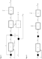
Figur 1 zeigt schematisch die Übersicht des erfindungsgemäßen Verfahren. -
Figur 2 zeigt schematisch das aktuelle Verfahren zeigt, auf das sich das Vergleichsbeispiel bezieht. -
Figuren 3 bis 5 zeigen jeweils eine Detailansicht des Oxygenat-Reaktors und dessen Aufreinigung für die erfindungsgemäßen Beispiel E3 bis E5. - Vergleichsbeispiel V1: Herstellung von Blausäure aus Methan und Ammoniak und anschließende Umsetzung zu Methylmethacrylat (MMA) unter Verwendung von nicht prozess-gekoppeltem Methanol
- Die Synthese der Blausäure erfolgt nach dem BMA-Verfahren (Details dazu können in
DE 1013636 B nachgelesen werden) wie folgt: Die Analyse des Reaktions- und Prozessgases erfolgte mittels online-µGC, welche mit einer Genauigkeit von ± 0.2 % ausgewiesen ist. - Die Darstellung der Blausäure erfolgt im Reaktor A, welcher räumlich in die zwei Teile A1 und A2 getrennt ist.
- 636 kg/h Synthesemethan, mit einer typischen Zusammensetzung von 95,1 Gew% Methan, 4,47 Gew% Wasserstoff, 0,23 Gew% Kohlenstoffmonoxid, jeweils < 0,1 Gew% Stickstoff, Ethan und Ethylen, werden mit 724 kg/h Ammoniak, mit einer typischen Zusammensetzung von 99,5 Gew% Ammoniak und 0,5 Gew% Wasser, dem Reaktorteil A1 zugeführt und zur Reaktion gebracht.
- Der Reaktor A1 besteht aus 1350 mit Platin beschichteten (gemäß
DE 3923034 ,DE 19617040 ) Reaktionsrohren mit einer Länge von 2100 mm und einem Innendurchmesser von 16 mm, welche in mehreren Kammern mit bis zu je 66 Rohren angeordnet sind. Der Reaktor wird bei einer Temperatur größer 1000 °C und einem Unterdruck von -50 mbarü betrieben. Die Temperatur wird durch Verbrennen von 486 kg/h einer Mischung von handelsüblichem Erdgas, mit einem Methangehalt größer 90 %, und Wasserstoff im Masseverhältnis von Zwei zu Eins mit 9315 kg/h Luft in Reaktorteil A2 erzeugt. Dabei entsteht ein Abgasstrom (Prozessstrom II) von 9818 kg/h, welcher 775 kg/h CO2 und 2,5 % Restsauerstoff sowie 2000 mg/m3 NOx enthält, welche anschließend durch eine nichtkatalytische Reduktion mit Ammoniak auf 300 mg/m3 reduziert wird. Der Abgasstrom wird anschließend in die Atmosphäre gegeben. - Der den Reaktor A1 verlassende Prozessstrom I hat typischerweise eine Zusammensetzung von 22 Vol% Blausäure, 3 Vol% Ammoniak, 1 Vol% Methan und 74 Vol% Wasserstoff. Dieser wird in einem dem Reaktor zugehörigen Wärmtauscher auf <200°C abgekühlt und bei einem Druck von -25 mbarü der nachfolgenden Absorptionsstufe I zugeführt.
- Das Ammoniak wird durch Zuführen in Absorptionsstufe I, ausgeführt als zweistufige Säurewäsche, mittels 30 gew%iger Schwefelsäure aus dem Prozessgasstrom I abgetrennt, wodurch Prozessgasstrom II erhalten wird. 1100 kg/h der dabei entstehende Ammoniumsulfatlösung werden aus dem Prozess ausgeschleust.
- Durch Zuführen des Prozessgasstrom II in die Absorptionsstufe II wird die im Prozessgasstrom II enthaltene Blausäure bei einer Temperatur von 8 °C und einem Druck von -25 mbarü, mit 24.000 kg/h
- Wasser aus dem Gasstrom ausgewaschen, wodurch 25.000 kg/h 4 Gew%ige wässrige Blausäurelösung und 267 kg/h eines Restgases, mit einer Zusammensetzung von 98 % Wasserstoff, 1 % Methan und 1 % Stickstoff, entstehen. 75 % dieses Stroms werden in den Reaktorteil A2 für die beschriebene Beheizung zurückgeführt.
- Die 25.000 kg/h Blausäurelösung werden anschließend mittels Rektifikation in Wasser, welches in die Absorptionsstufe II zurückgeführt wird, und Blausäure, mit einer Reinheit von >99 %, aufgetrennt.
- Es entstehen 1000 kg/h Blausäure, was einer Ausbeute, bezogen auf den Methaneinsatz, von 98,4 % entspricht. Zur Herstellung von 1000kg/h HCN, werden 35 GJ/h benötigt.
- Die Blausäure wird in einem zweiten Prozessschritt zu Acetoncyanhydrin (ACH) weiterverarbeitet. Dazu werden 1000 kg/h HCN mit 2140 kg/h Aceton und 2 kg/h Diethylamin vermischt und in einem vierstufigen Reaktorsystem bei jeweiligen Temperaturen von 33 °C, 18 °C, 5 °C und -5 °C umgesetzt. Es werden 3650 kg/h Roh-ACH, mit einer Zusammensetzung von 93 % ACH, 2,5% Aceton, 2,5% HCN (Rest inerte, Nebenprodukte), erhalten, welches anschließend in einem zweistufigen Verdampfersystem aufgereinigt wird. In der ersten Stufe werden bei 120 mbar und 82 °C und in der zweiten Stufe bei 40 mbar und 85 °C die Leichtsieder Aceton und HCN als Brüdenstrom abgetrennt und kondensiert. Es wird ein Destillatstrom von 475 kg/h, mit einer Zusammensetzung von 83 % ACH, 15 % Aceton und 2 % HCN, erhalten, welcher in die Reaktionsstufe 1 zurückgeführt wird. Am Sumpfablauf der Verdampfer entsteht ein Rein-ACH-Strom (99,5 %) von 3000 kg/h.
- Im dritten Prozessschritt wird ACH zum Methacrylamid umgesetzt. Dazu werden 1834 kg/h ACH mit 4941 kg/h hochkonzentrierter Schwefelsäure bei <100°C in den ersten Amidierungsreaktor gegeben. Für die Produktion der Schwefelsäure werden 550 kg/h Erdgas für die Feuerung benötigt. Zusammen mit der Verbrennung von Restorganik in der Spaltsäure ergeben sich hierbei 2569 kg/h CO2-Emissionen. Dem Produktstrom werden anschließend weitere 1166 kg/h ACH zugeben und das Gemisch wird einem zweiten Amidierungsreaktor zugeführt. Anschließend wird das Gemisch bei 160 °C und mehreren Minuten Verweilzeit konvertiert. 7933 kg/h des so erhaltenen Amidgemischs, enthaltend 36 Gew% Methacrylamid, werden mit 1125 kg/h Methanol und 1200kg/h Wasser anschließend zur Veresterung einer sechsstufigen Reaktorkaskade zugeführt. Nach der Aufreinigung mittels Roh- und zweistufiger Rein-Rektifikation werden schließlich 3426 kg/h Methylmethacrylat mit einer Ausbeute bezogen auf das eingesetzte ACH von 91 % erhalten.
- Bezogen auf die Produktion eines kg MMAs leiten sich Verbrauchszahlen bzw. Einsatzfaktoren für die einzelnen Rohstoffe ab, sowie die Emissionen aus Schwefelsäure Produktion und HCN Synthese (BMA) (siehe Tabelle 1).
- Die Nachfolgende Ökobilanzierung soll die Umweltauswirkungen des produzierten MMAs bezgl. der CO2 Emissionen bewerten mit der Systemgrenze Cradle-to-Gate - sogenannter Product-Carbon-Footprint (PCF). Hierbei werden nicht nur die direkten CO2-Emission aus dem Prozess (Scope 1) sondern auch die CO2-Emissionen aus den Rohstoffvorketten berücksichtigt (Scope 3)..Die indirekten COz-Emissionen der Energien (Scope 2) werden vernachlässigt, da die Produktion des elektrischen Stroms aus rein regenerativen Quellen angenommen wird und Dampf als Wärmequelle aus der Exothermie bzw. Abwärme des MMA-Prozesses selbst produziert wird. Alle CO2-Emissionen werden auf ein 1 kg produziertes MMA bezogen (Funktionelle Einheit FU). Die Datenquelle für die Primärdaten sind aus den Beispielen zu entnehmen, die sekundär Daten, also die spezifischen CO2-Emissionen der Rohstoffe, stammen von PlasticsEurope (EcoProfiles). Für Methanol wird ein Wert aus der Literatur angesetzt (Methanol-Mangaging greenhouse gas emissions in the production chain by optimizing the resource base; AIMS Energy; DOI: 10.3934/energy.2018.6.1074). Die genannten Rohstoffe sind mehr als 99% der gesamten eingesetzten Masse. Alle anderen Stoffströme werden hier nicht berücksichtigt Generell wurde diese Ökobilanz nach der ISO 14040/14044 durchgeführt. Für die Umweltwirkungsbewertung wurde die Folgeabschätzung des niederländische Forschungszentrum für Umweltwissenschaften Leiden (CML) mit Charakterisierungsfaktoren aus dem Jahr 2011 mit Aktualisierung April 2013 verwendet.
- Die Menge an Rohstoffen und ausgestoßenen CO2-Emissionen beziehen sich auf das oben beschriebene Vergleichsbeispiel für 1000 kg/h Blausäure bzw. 3424 kg/h MMA.
- Mit der Menge und den spezifischen Emissionen lassen sich die einzelnen COz-Emissionen der Rohstoffe spezifisch wie auch absolut berechnen.
Tabelle 1: Datengrundlage und Berechnung des Product Carbon Footprints von MMA für das Vergleichsbeispiel V1. PCF Edukt / kgCO2äq./kg Eingesetzte Menge pro Stunde / kg CO2äq-Emission kgCO2äq. Upstream Emissionen Methan 0,52 636 330 Erdgas (BMA + H2SO4) 0,52 826 429 276 +550 NH3 2,4 724 1737 Aceton 1,6 2140 3424 Methanol (Erdgas basierend) 0,83 1152 956 H2 Export 1,6 66,7 -106,8 Teilsumme 6769 Produktion Direkte CO2-Emissionen (BMA + H2SO4) 3344 (775+2569) 3344 (775+2569) MMA 3424 10113 PCF 2,95 kgCO2äq./kg MMA - Mit dem Quotienten aus total CO2-Emissionen und MMA Produktion ergibt sich ein PCF von 2,95 kgCO2äq./kg MMA.
- In Tabelle 1 ist zu sehen, dass ca. 2/3 der CO2-Emissionen bei der MMA Produktion auf die Rohstoffe zurückzuführen sind. Die direkten Emissionen stammen zu 23% aus dem BMA-Verfahren und zu 76% aus der Schwefelsäureanlage.
- Im erfindungsgemäßem Beispiel E1 werden analog dem Vergleichsbeispiel V1 636 kg/h Synthesemethan, mit einer typischen Zusammensetzung von 95,1 Gew% Methan, 4,47 Gew% Wasserstoff, 0,23 Gew% Kohlenstoffmonoxid, < 0,1 Gew% Stickstoff, Ethan und Ethylen, mit 724 kg/h Ammoniak, mit einer typischen Zusammensetzung von 99,5 Gew% Ammoniak und 0,5 Gew% Wasser,in den Reaktorteil A1 gegeben. Es entstehen analog dazu 1000 kg/h Blausäure und 267 kg/h des wasserstoffreichen Restgases.
- Für die Beheizung des Reaktors wird ein 300 bis 400 °C heißer Rauchgas-Recyclestrom von 3881 kg/h, bestehend aus 55 Gew% CO2, 44 Gew% H2O und 1 Gew% O2, mit 2751 kg/h technisch reinem Sauerstoff sowie 690 kg/h handelsüblichem Erdgas, mit einem Methangehalt > 90 Gew%, im Reaktorteil A2 thermisch umgesetzt. Es entstehen dabei 7323 kg/h eines Rauchgases von dem 53% kontinuierlich abgetrennt werden und für den beschriebenen Rauchgas-Recyclestrom dienen. Der andere Teil des Stroms wird mittels eines Edelmetallkatalysators und eines kohlenstoffhaltigen Reduktionsmittels desoxigeniert. Nach einer Abkühlung auf 20 °C und Abtrennung von auskondensiertem Wasser erhält man einen Strom mit 2019 kg/h mit einem CO2 Anteil von 98 Gew% und < 25 mg/m3 NOx (Rest Wasser). Mit Rauchgas wird in diesem Zusammenhang des vorliegenden Beispiels der Prozessstrom IV gemäß Beschreibung aufgeführt.
- Im erfindungsgemäßen Beispiel E1 wird in einem nächsten Prozessschritt dieser CO2-Strom mit den 267 kg/h Restgas mit einem H2-Gehalt von 98 Gew%, welches aus dem Reaktorteil A1 erhalten wurde, vermischt und mittels mehrstufiger Kompression auf 85 bar verdichtet. Zwischen den Kompressionsstufen wird nach der Kühlung kondensiertes Wasser von der Gasphase abgetrennt. Die Zusammensetzung des gemischten Gases beträgt dann 72,1 Vol% H2, 24,3 Vol% CO2, und 3,6 Vol% H2O. Dies entspricht einer Stöchiometriezahl von 1,96.
- Das gemischte und komprimierte Synthesegas wird anschließend zusammen mit dem Kreislaufgas in einen ersten Wärmetauscher geleitet. Die Eintrittstemperatur beträgt hierbei 67 °C und die Austrittstemperatur 220 °C. Das vorgewärmte Gas weist eine Zusammensetzung von 77,2 Vol% H2, 20,3 Vol% CO2, 2,1 Vol% CO, 0,28 Vol% MeOH owie 0,11 Vol% H2O mit einem Volumenstrom von 19061 Nm3/h auf. Das Gas wird anschließend auf die Rohrseite eines Rohrbündel-Reaktors geleitet, bei der unter Wärmeentwicklung an einem Kupfer/Zink/Aluminumoxid-haltigem Katalysator (bspw. Clariant MegaMax MM800) in Pelletform (6 x 4 mm) die Reaktion einsetzt. Die entstehende Wärme wird durch das siedende Wasser bei 40 bar Druck auf der Mantelseite abtransportiert. Die Umsätze im geraden Durchgang für H2 und CO2 sind 20 % respektive 25 % bei einer Verweilzeit von 8,7 Sekunden und einer Katalysatorbettporosität von 0,38. Die produzierte Sattdampfmenge beträgt hierbei 500 kg/h. Das reagierte Reaktoraustrittsgas weist eine Austrittstemperatur von 251 °C auf mit einer Zusammensetzung von 69 Vol% H2, 16,9 Vol% CO2, 5,8 Vol% MeOH, 5,7 Vol% H2O und 2,3 Vol% CO sowie einer Volumenstrommenge von 17163 Nm3/h. Das Gas wird weiter in den ersten Wärmetauscher geleitet und auf 130 °C abgekühlt. In dem Schlusskühler wird mittels Kühlwasser (mit einem Vorlauf von 30 °C) das Prozessgas auf 40 °C abgekühlt, wobei flüssige Produkte auskondensieren. Die Flüssigphase (sogenanntes Rohmethanol) weißt bei 83,7 bar eine Zusammensetzung von 62,9 Gew% MeOH, 35,9 Gew% H2O und 1,12 Gew% gelöstem CO2 auf. Weitere Nebenprodukte sind 700 Gew-ppm EtOH und 50 Gew-ppm Dimethylether. Der gesamte Massenstrom beträgt 2150 kg/h.
- Nach der Abtrennung der Flüssig- und der Gasphase wird das unreagierte Gas mit Hilfe eines Kreislaufkompressors wieder mit dem Synthesegas gemischt. Der Volumenstrom des Kreislaufgases beträgt 15237 Nm3/h. Das Kreislaufverhältnis zwischen Kreislaufgas und Synthesegas beträgt hierbei 3,8. Um die Akkumulierung von inerten Komponenten zu verhindern wird aus dem Kreislaufgas ein Spülgasstrom abgezweigt mit einem Massenstrom von 49 kg/h. Der Gesamtumsatz von H2 beträgt 98%. Das flüssige Rohmethanol wird in einen Rohmethanoltank auf 3 bis 5 bar entspannt, wobei sich gelöste Gase (vor allem CO2) freisetzen.
- In der anschließenden Vorlaufkolonne bei Umgebungsdruck und 75 °C Sumpftemperatur werden weitere Gase (DME) aus dem Rohmethanol abgetrennt. Die Kopftemperatur liegt bei 65,4 °C mit einem Reflux-Verhältnis (mol/mol) von 1.
- Alle Abgase vom Spülgasstrom, Rohmethanoltank und Vorlaufkolonne werden zusammen in eine gemeinsame Verbrennungskammer zusammen mit Luft zu CO2 und H2O verbrannt. Die entstehenden CO2 Emission belaufen sich auf 75 kg/h.
- Das im Sumpf erhaltene stabilisierte Rohmethanol wird in der nachfolgenden Produktkolonne bei Umgebungsdruck rektifiziert, wobei H2O im Sumpf mit einer Temperatur von 99 °C, einer Zusammensetzung von 0,11 Gew% MEOH, 376 Gew-ppm EtOH und einem gesamt Massenstrom von 676 kg/h erhalten wird. Das fertige Methanolprodukt im Kopf der Kolonne wird mit einer Temperatur von 64 °C und einem EtOH-Gehalt von 8,2 Gew-ppm gewonnen. Die Produktionsrate liegt bei 1410 kg/h. Das Reflux-Verhältnis der Kolonne beträgt 3,4. Zur Stabilisation der Kolonne und Gewährleistung der Produktsowie Abwasserspezifikation wird durch eine Seitenstromabtrennung im unteren Teil der Kolonne Nebenprodukte (hauptsächlich EtOH) mit einer Zusammensetzung von 92,5 Gew% H2O, 4,1 Gew% MeOH und 3,3 Gew% EtOH und einem gesamt Massenstrom von 32,9 kg/h abgetrennt.
- Das produzierte Methanol wird analog des Vergleichsbeispiels V1, mit Methacrylamid und Wasser zu Methylmethacrylat umgesetzt werden.
Tabelle 2: Datengrundlage und Berechnung des Product Carbon Footprints von MMA für das Beispiel E1 PCF Edukt / kgCO2äq./kg Eingesetzte Menge pro Stunde / kg CO2äq-Emission / kgCO2äq/h Upstream Emissionen Methan 0,52 636 330 Erdgas BMA + H2SO4 0,52 1240 (690 +550) 644 NH3 2,4 724 1737 Aceton 1,6 2140 3424 Methanol (Erdgas basierend) 0,83 -258 (1152-1410) -214 O2 (gasförmig) 0 2751 0 Teilsumme 5921 H2 export 1,6 0 0 Produktion Direkte CO2-Emissionen (H2SO4 + MeOH) 2644 (2569+75) 2644 MMA 3424 8565 PCF 2,5 kgCO2äq./kg MMA - Mit dem Quotienten aus total CO2-Emissionen und MMA Produktion ergibt sich ein PCH von 2,5 kgCO2äq./kg MMA.
- Durch die Konversion von direkten Emissionen der Blausäure mit dem dort erzeugten Wasserstoff lassen sich nicht nur die direkten Emissionen um 21% senken, sondern auch der Scope 3 Anteil wird um 5% reduziert. Die Überproduktion an Methanol, wird hier mit einer CO2-Gutschrift berechnet. Durch den erhöhten Einsatz an Erdgas wird die Gutschrift von der Methanolproduktion teilweise kompensiert. Die Sauerstoffproduktion über eine cryogene Luftzerlegung erfolgt mit regenerativer elektrischer Energie, so dass hier keine (indirekten) Emissionen anfallen.
- Am Ende kann das Beispiel zeigen, dass die CO2-Emissionen um 15% gegenüber dem Vergleichsbeispiel reduziert werden konnten.
- Im erfindungsgemäßem Beispiel E2a werden analog dem erfindungsgemäßem Beispiel E1 636 kg/h Synthesemethan, mit einer typischen Zusammensetzung von 95,1 Gew% Methan, 4,47 Gew% Wasserstoff, 0,23 Gew% Kohlenstoffmonoxid, jeweils < 0,1 Gew% Stickstoff, Ethan und Ethylen, mit 724 kg/h Ammoniak, mit einer typischen Zusammensetzung von 99,5 Gew% Ammoniak und 0,5 Gew% Wasser, in den Reaktorteil A1 gegeben. Es entstehen analog dazu 1000 kg/h Blausäure und 267 kg/h des wasserstoffreichen Restgases.
- Die Beheizung des Reaktors erfolgt durch unterstöchiometrisches Verbrennen von 690 kg/h handelsüblichem Erdgas, mit einem Methangehalt von über 90 %, mit 2688 kg/h Sauerstoff unter Zugabe von 3809 kg/h eines 300 bis 400 °C heißen Recyclestroms, bestehend aus 55 Gew% CO2, 44 Gew% H2O und 1 Gew% CO, in Reaktorteil A2.
- Es entstehen dabei 7187 kg/h Rauchgas, von dem 53% abgetrennt werden und für den beschriebenen Rauchgas-Recyclestrom dienen. Nach einer Abkühlung auf 20 °C und Abtrennung von auskondensiertem Wasser werden 1942 kg/h eines Kohlenoxidstrom mit einem CO2 Anteil von 97 Gew%,einem CO Anteil von 1 Gew%,einem Sauerstoffgehalt < 1000 Gew-ppm und einem NOx-Gehalt < 25 mg/m3 erhalten. Mit Rauchgas wird in diesem Zusammenhang des vorliegenden Beispiels der Prozessstrom IV gemäß Beschreibung aufgeführt.
- Analog dem erfindungsgemäßem Beispiel E1 wird anschließend der Kohlenoxidstrom mit dem wasserstoffhaltigen Restgasstrom zu Methanol umgesetzt und dieses dann wie auch die hergestellte Blausäure für die Prodiktion von Methylmethacrylat verwendet.
- Die Methanolproduktion steigt dabei um 2% gegenüber dem Beispiel E1 auf 1440 kg/h bei gleichem H2 Einsatzes.
- Die einzelnen Mengenströme sind in der Tabelle 3 für die Analyse des CO2-Fußabdruckes zusammengefasst
Tabelle 3: Datengrundlage und Berechnung des Product Carbon Footprints von MMA für das Beispiel E2a PCF Edukt / kgCO2äq./kg Eingesetzte Menge pro Stunde / kg CO2äq-Emission / kgCO2äq/h Upstream Emissionen Methan 0,52 636 330 Erdgas 0,52 1240 (690 +550) 644 NH3 2,4 724 1737 Aceton 1,6 2140 3424 Methanol (Erdgas basierend) 0,83 -288 1152-1440 -239 O2 (gasförmig) 0 2688 0 H2 export 1,6 0 0 Teilsumme 5896 Output Direkte CO2-Emissionen (H2SO4 + MeOH) 2645 (2569+76) 2645 (2569+76) MMA 3424 8541 PCF 2,49 kgCO2äq/kg MMA - Mit dem Quotienten aus total CO2-Emissionen und MMA Produktion ergibt sich ein leicht niedrigerer PCF von 2,49 kgCO2äq/kg MMA.
- Im erfindungsgemäßem Beispiel E2b werden analog dem erfindungsgemäßem Beispiel E1 636 kg/h Synthesemethan, mit einer typischen Zusammensetzung von 95,1 Gew% Methan, 4,47 Gew% Wasserstoff, 0,23 Gew% Kohlenstoffmonoxid, jeweils < 0,1 Gew% Stickstoff, Ethan und Ethylen, mit 724 kg/h Ammoniak, mit einer typischen Zusammensetzung von 99,5 Gew% Ammoniak und 0,5 Gew% Wasser, in den Reaktorteil A1 gegeben. Es entstehen analog dazu 1000 kg/h Blausäure und 267 kg/h des wasserstoffreichen Restgases.
- Durch weitere Reduktion des C/O-Verhältnisses für die Beheizung des Reaktors unter Beibehaltung der Reaktionswärme bzw. Temperatur konnte überraschenderweise eine parallele Synthesegas Produktion (analog einer partiellen Oxidation) durchgeführt werden.
- Hierbei erfolgt die Beheizung des Reaktors analog zu dem Beispiel E2a durch unterstöchiometrisches Verbrennen von 1467 kg/h handelsüblichem Erdgas, mit einem Methangehalt von über 90 %, mit 4032 kg/h Sauerstoff unter Zugabe von 3809 kg/h eines 300 bis 400 °C heißen Recyclestroms, bestehend aus 16 Gew% CO2, 42 Gew% H2O, 17 Gew% CO und 24 vol% H2 sowie Reste an Methan, in Reaktorteil A2.
- Es entstehen dabei 13746 kg/h Rauchgas bzw. Synthesegase, von dem 40% abgetrennt werden und für den beschriebenen Recyclestrom dienen. Nach einer Abkühlung auf 20 °C und Abtrennung von auskondensiertem Wasser werden 3450 kg/h eines Synthesegasstromes mit einer Zusammensetzung (in vol.%) von 41 H2, 29 CO, 27 CO2 und 2,3 H2O sowie Spuren von Methan erhalten. Mit Rauchgas wird in diesem Zusammenhang des vorliegenden Beispiels der Prozessstrom IV gemäß Beschreibung aufgeführt.
- Die Mischung zusammen mit wasserstoffhaltigem Restgas ergibt ein Synthesegas mit einer Zusammensetzung von 67 vol%. H2, 16 vol.% CO, 14,9 vol.% CO2 sowie Resten von H2O und Methan. Analog dem erfindungsgemäßem Beispiel E1 wird anschließend der Synthesegasstrom mit zu Methanol umgesetzt und dieses dann wie auch die hergestellte Blausäure für die Prodiktion von Methylmethacrylat verwendet.
- Die Methanolproduktion konnte dabei deutlich auf 2550 kg/hr gegenüber dem Beispiel E1 gesteigert werden. Dies entspricht einer Erhöhung um 77 %. Die Überproduktion an Methanol beträgt 1398 kg/hr.
- Die einzelnen Mengenströme sind in der Tabelle 3 für die Analyse des CO2-Fußabdruckes zusammengefasst
Tabelle 4: Datengrundlage und Berechnung des Product Carbon Footprints von MMA für das Beispiel E2b PCF Edukt / kgCO2äq./kg Eingesetzte Menge pro Stunde / kg CO2äq-Emission / kgCO2äq/h Upstream Emissionen Methan 0,52 636 330 Erdgas 0,52 2017 (1467 +550) 1048 NH3 2,4 724 1737 Aceton 1,6 2140 3424 Methanol (Erdgas basierend) 0,83 -1398 1152-2550 -1160 O2 (gasförmig) 0 4032 0 H2 export 1,6 0 0 Teilsumme 5380 Output Direkte CO2-Emissionen (H2SO4 + MeOH) 2645 (2569+76) 2645 (2569+76) MMA 3424 8024 PCF 2,34 kgCO2äq/kg MMA - Das Ergebnis der Analyse der CO2-Emissionen zeigt auf überraschende Weise, dass sich trotz höherer Erdgasmengen, die für die Bereitstellung von Thermischer Energie für die BMA-Reaktion als auch für die Synthesegaserzeugung innerhalb der Brennkammer des BMA-reaktor benötigt wird, die Produktion des Methanols sich positiv für den PCF des MMAs auswirkt. Mit der Annahme, dass die Methanolüberproduktion mit einem konventionellen CO2-Faktor vergütet werden kann, werden hierbei 1160 kg/hr CO2äq. Eingespart. Am Ende liegt der PCF bei diesem Beispiel bei 2,34 kgCO2äq/kg MMA, was einer Reduktion von 22% entspricht.
- Im erfindungsgemäßem Beispiel E3 werden analog dem erfindungsgemäßem Beispiel E1 636 kg/h Synthesemethan, mit einer typischen Zusammensetzung von 95,1 Gew% Methan, 4,47 Gew% Wasserstoff, 0,23 Gew% Kohlenstoffmonoxid, < 0,1 Gew% Stickstoff, Ethan und Ethylen, mit 724 kg/h Ammoniak, mit einer typischen Zusammensetzung von 99,5 Gew% Ammoniak und 0,5 Gew% Wasser, in den Reaktorteil A1 gegeben. Es entstehen analog dazu 1000 kg/h Blausäure und 267 kg/h des wasserstoffreichen Restgases.
- Die Beheizung des Reaktors erfolgt analog dem erfindungsgemäßem Beispiel E1. Nach Abkühlen auf 20 °C und Abtrennung von auskondensiertem Wasser erhält man einen Strom von 2019 kg/h mit einem CO2 Anteil von 98 Gew% und < 25 mg/m3 NOx. Der Rest ist überwiegend Wasser.
- 62% dieses CO2-reichen Gasstroms wird zu einem CO-Generator auf Basis einer SOEC (Solid Oxid Electrolysis Cell) (siehe Artikel "Small-Scale CO from CO2 using Electrolysis" in "Chemical Engineering World; Seite 44 - 46; März 2017) zusammen mit elektrischem Strom zu einem CO-reichem Strom konvertiert. Die Zusammensetzung diese Produktstromes beträgt 99 Vol% CO sowie 1 Vol% CO2 mit einem Volumenstrom von 778 kg/h. Es entstehen weiterhin 438 kg/h Sauerstoff. Der elektrische Stromverbrauch liegt hierbei bei 4,4 MW.
- Der CO-reiche Strom wird anschließend zusammen mit einem Teil (5%) des wasserstoffreichem Restgases aus der BMA Anlage, dem Bypass des Kohlendioxidstroms und dem CO Recyclegasstrom zu einem Synthesegas mit einer Zusammensetzung von 50 Vol% CO, 30 Vol% CO2, 10 Vol% H2 und 10 Vol% N2 gemischt. Der Großteil des H2-Stroms (247 kg/h) wird in die Feuerung der H2SO4 Anlage eingesetzt, um das Erdgas dort zu substituieren und somit keine (direkten) CO2-Emissionen zu erzeugen.
- Das gemischte Synthesegas wird anschließend in einem Bioreaktor gemäß dem in der Literatur beschriebenen Verfahren (
US 2012/0252083 , F. E. Liew et al. Carbon-negative production of acetone and isopropanol by gas fermentation at industrial pilot scale, Nature Biotechnology 40, 335-344 (2022)) zu Aceton umgesetzt. Hierbei wird das oben beschriebene Synthesegas mit 1568 Nm3/h bei 35 °C in einem kontinuierlich betriebenen Rührkessel (V=550 m3) bei 1,4 bar, welcher modifizierte Clostridium autoethanogenum enthält, gegeben. - Der Umsatz im geraden Durchgang bezogen auf das CO ist 80% und die Selektivität von CO zu Aceton liegt bei 80%. Es wird ein Produktstrom von 237 kg/h enthalten, welcher aus 80 Gew% Aceton, 15 Gew% Acetessigsäure, 2,5 Gew% Ethanol und 2,5 Gew% iso-Propanol besteht.
- Dieses Gemisch wird anschließend mittels Rektifikation aufgereinigt. Als Kopfprodukt fallen 194 kg/h Aceton mit einer Reinheit von 99,5 % an. Als Sumpfprodukt werden 43 kg/h (35 Gew% Aceton, 50 Gew% Acetessigsäure, 7 Gew% Ethanol und 8 Gew% iso-Propanol) ausgeschleust und in einem weiterem Prozessschritt aufgearbeitet.
- Das produzierte Aceton wird zusammen mit 1946 kg/h konventionellem Aceton analog des Vergleichsbeispiels V1 erst zu ACH und anschließend weiter zu Methacrylamid und Wasser sowie zu Methylmethacrylat umgesetzt.
- Das unreagierte Gas wird zunächst über einen Kompressor auf 15 bar gebracht, um anschließend in eine Druckwechseladsorptionsanlage geleitet zu werden. Hier wird bei einer Effizienz von 90% das CO zurückgewonnen und als Recyclinggasstrom (246 Nm3/h) mit einer Zusammensetzung von 69 Vol% CO und 30 Vol% CO2 in den Bioreaktor zurückgefahren. Der Tailgasstorm aus der PSA mit einer Zusammensetzung von 76 Vol% CO2, 17,8 Vol% N2 und 2,1 Vol% CO und einem Volumenstrom von 873 Nm3/h wird in der H2SO4 Anlage thermisch verwertet.
Tabelle 5: Datengrundlage und Berechnung des Product Carbon Footprints von MMA für das Beispiel E3 PCF Edukt / kgCO2äq./kg Eingesetzte Menge pro Stunde / kg Produkt-Carbon-Footprint / kgCO2äq. Upstream Emissionen Methan 0,52 636 330 Erdgas 0,52 1240 644 NH3 2,4 724 1737 Aceton 1,6 1946 3113 Methanol (Erdgas basierend) 0,83 1152 954 O2 (gasförmig) 0 2250 (2699 - 438) 0 H2 export 1,6 0 0 Teilergebnis 6778 Output Direkte CO2-Emissionen (H2SO4+Aceton) 2353 (1324+1029) 2353 MMA 3424 9131 PCF 2,66 kgCO2.äq/kg MMA - Der PCF verringert sich mit diesem Beispiel auf 2,66 kgCO2.äq/kg MMA, was einer Reduktion in Bezug auf das Vergleichsbeispiel von 10 % entspricht.
- Im erfindungsgemäßem Beispiel E3 werden analog dem erfindungsgemäßem Beispiel E1 636 kg/h Synthesemethan, mit einer typischen Zusammensetzung von 95,1 Gew% Methan, 4,47 Gew% Wasserstoff, 0,23 Gew% Kohlenstoffmonoxid, < 0,1 Gew% Stickstoff, Ethan und Ethylen, mit 724 kg/h Ammoniak, mit einer typischen Zusammensetzung von 99,5 Gew% Ammoniak und 0,5 Gew% Wasser, in den Reaktorteil A1 gegeben. Es entstehen analog dazu 1000 kg/h Blausäure und 267 kg/h des wasserstoffreichen Restgases.
- Die Beheizung des Reaktors erfolgt analog dem erfindungsgemäßem Beispiel E1. Nach Abkühlen auf 20 °C und Abtrennung von auskondensiertem Wasser erhält man einen Strom von 2019 kg/h mit einem CO2 Anteil von 98 Gew% und < 25 mg/m3 NOx. Der Rest ist überwiegend Wasser.
- Der CO2-reiche Gasstrom wird zu einem CO-Generator auf Basis einer SOEC (Solid Oxid Electrolysis Cell) (siehe Artikel "Small-Scale CO from CO2 using Electrolysis" in "Chemical Engineering World; Seite 44 - 46; März 2017) zusammen mit elektrischem Strom zu einem CO-reichem Strom konvertiert. Die Zusammensetzung diese Produktstromes beträgt 99 Vol% CO sowie 1 Vol% CO2 mit einem Massestrom von 1282 kg/h. Es entstehen weiterhin 737 kg/h Sauerstoff, der wiederrum zur Verbrennung im BMA-Reaktor hinzugefügt werden kann. Der elektrische Stromverbrauch liegt hierbei bei 7,4 MW.
- Der CO-reiche Strom wird anschließend zusammen mit dem wasserstoffreichen Restgas aus der BMA Anlage zu einem Synthesegas mit einer Zusammensetzung von 61 Vol% H2, 37 Vol% CO, 0,4 Vol% CO2 und Rest H2O und N2 gemischt. Anschließend wird dieses gemischte Synthesegas in einem Bioreaktor gemäß dem in der Literatur beschriebenen Verfahren (
US 2012/0252083 , F. E. Liew et al. Carbon-negative production of acetone and isopropanol by gas fermentation at industrial pilot scale, Nature Biotechnology 40, 335-344 (2022)) zu Aceton umgesetzt. Hierbei wird das oben beschriebene Synthesegas mit 1549 kg/hr bei 35 °C in einem bzw. mehreren kontinuierlich betriebenen Rührkesseln mit einem gesamten Volumen von 1400 m3 bei 1,4 bar, welcher modifizierte Clostridium autoethanogenum enthält, gegeben. Der Umsatz bezogen auf das CO bzw. H2 ist 80% und die Selektivität von CO zu Aceton liegt bei 80%. Nach dem Abkühlen des Produktstroms auf 5°C und Abtrennung der nicht umgesetzten gasförmigen Edukte (H2 und CO) wird das Prozesswasser zunächst destillativ abgetrennt. Hierbei fällt ein Produktstrom von 385 kg/h an, welcher aus 80 Gew% Aceton, 15 Gew% Acetessigsäure, 2,5 Gew% Ethanol und 2,5 Gew% iso-Propanol besteht. - Dieses Gemisch wird anschließend mittels weiterer Rektifikation aufgereinigt. Als Kopfprodukt fallen 308 kg/h Aceton mit einer Reinheit von 99,5 % an. Als Sumpfprodukt werden 77 kg/h (35 Gew% Aceton, 50 Gew% Acetessigsäure, 7 Gew% Ethanol und 8 Gew% iso-Propanol) ausgeschleust und in einem weiterem Prozessschritt aufgearbeitet.
- Das nicht umgesetzte Synthesegas mit einer Zusammensetzung von 75 vol.% H2, 19 vol.% CO sowie Resten von H2O und CO2 mit einem Massestrom von 864,3 kg/hr wird in der Schwefelsäure-Anlage thermisch umgesetzt und substituiert dort zu 99% das Erdgas. Durch das höhere H/C Verhältnis des Purgegases im Vergleich zum Erdgas sinken die direkten CO2-Emission der H2SO4-Produktion um 14%.
- Das produzierte Aceton wird zusammen mit 1795 kg/h konventionellem Aceton analog des
- Vergleichsbeispiels V1 erst zu ACH und anschließend weiter zu Methacrylamid und Wasser sowie zu Methylmethacrylat umgesetzt.
Tabelle 6: Datengrundlage und Berechnung des Product Carbon Footprints von MMA für das Beispiel E4 PCF Edukt / kgCO2äq./kg Eingesetzte Menge pro Stunde / kg Produkt-Carbon-Footprint / kgCO2äq. Upstream Emissionen Methan 0,52 636 330 Erdgas 0,52 782 406 NH3 2,4 724 1737 Aceton 1,6 1832 (2140 - 308) 2931 Methanol (Erdgas basierend) 0,83 1152 954 O2 (gasförmig) 0 1951 (2688-737) 0 H2 export 1,6 0 0 Teilergebnis 6358 Output Direkte CO2-Emissionen 2357 2357 MMA 3424 8715 PCF 2,54 kgCO2äq./kg MMA - Dieses Beispiel zeigt, dass sich durch optimierte Bedingung für die biogene Herstellung von Aceton den CO2-Fußabdruck des gesamten MMA-Prozess weiter gemindert werden kann. Der PCF liegt hierbei bei 2,54 kgCO2äq./kg MMA, was einer Reduktion von 14% entspricht.
- Im erfindungsgemäßem Beispiel E5 werden analog dem erfindungsgemäßem Beispiel E1 636 kg/h Synthesemethan, mit einer typischen Zusammensetzung von 95,1 Gew% Methan, 4,47 Gew% Wasserstoff, 0,23 Gew% Kohlenstoffmonoxid, < 0,1 Gew% Stickstoff, Ethan und Ethylen, mit 724 kg/h Ammoniak, mit einer typischen Zusammensetzung von 99,5 Gew% Ammoniak und 0,5 Gew% Wasser, in den Reaktorteil A1 gegeben. Es entstehen analog dazu 1000 kg/h Blausäure und 267 kg/h des wasserstoffreichen Restgases.
- Die Beheizung des Reaktors erfolgt analog dem erfindungsgemäßem Beispiel E1. Nach Abkühlen auf 20 °C und Abtrennung von auskondensiertem Wasser erhält man einen Strom von 2019 kg/h mit einem CO2 Anteil von 98 Gew% und < 25 mg/m3 NOx. Der Rest ist überwiegend Wasser.
- Der CO2-reiche Gasstrom wird anschließend einer partiellen Oxidationseinheit mit integriertem elektrischen Plasmalichtbogen zu geführt (siehe Caphenia Patent
US 10,906,806 US 10,927,007 - Das Verfahren der Aceton Herstellung ist Analog zu dem Verfahren in Beispiel E4 beschrieben. Zusätzlich wird in diesem Beispiel das unreagierte Purgegas mit Hilfe eines Gebläses wieder in den Bioreaktor zurückgeführt. Dadurch steigert sich der gesamt CO Umsatz auf 95% bei gelichbleibender Selektivität von CO zu Aceton von 80%. Nach der Produktaufreinigung (analog zum Beispiel E4) erhält man einen Produktstrom von 1276 kg/hr Aceton.
- Das entstandene Purge mit 958 kg/hr und einer Zusammensetzung von 30 vol.% H2, 36 vol.% CO2, 13 vol.% sowie 12 vol.% Methan wird in die Feuerung der H2SO4-Anlage geleitet und ersetzt dort 40% des Erdgases für die Stützfeuerung.
- Ein Teil des wasserstoffreiche Stroms (134 kg/hr 50%) aus dem BMA-Reaktor wird ebenfalls für die Feuerung der H2SO4 Anlage verwendet und ersetzt dort die restlichen 60% des Erdgases. Die andere Hälfte 134 kg/hr ist für den Export bestimmt und wird mit einem CO2äq-Faktor von 1,6 kgCO2äq./kg vergütet.
- Das produzierte Aceton wird zusammen mit 864 kg/h konventionellem Aceton analog des Vergleichsbeispiels V1 erst zu ACH und anschließend weiter zu Methacrylamid und Wasser sowie zu Methylmethacrylat umgesetzt.
Tabelle 7: Datengrundlage und Berechnung des Product Carbon Footprints von MMA für das Beispiel E5. PCF Edukt / kgCO2äq./kg Eingesetzte Menge pro Stunde / kg Produkt-Carbon-Footprint / kgCO2äq. Upstream Emissionen Methan 0,52 636 330 Erdgas 0,52 1791 931 NH3 2,4 724 1737 Aceton 1,6 864 (2140 - 1276) 872 Methanol (Erdgas basierend) 0,83 1152 956 O2 (gasförmig) 0 2751 0 H2 export 1,6 134 -214 Teilergebnis 5122 Output Direkte CO2-Emissionen 1931 1931 MMA 3424 6919 PCF 2,06 kgCO2äq./kg MMA - Dieses Beispiel zeigt, dass durch die Co-Reformierung des CO2s mit Erdgas, Wasserdampf und elektrischem Strom der PCF deutlich gesenkt werden. Dieser liegt bei 2,06 kgCO2äq./kg MMA, was einer Reduktion von 31% in Bezug auf das Vergleichsspiel entspricht.
Zusammenfassung der Ergebnisse: (siehe Tabelle 8) - Die in Tabelle 8 dargestellten Ergebnissen zu den Vergleichs- sowie Patentbeispielen zeigen, dass alle Beispiele die Aufgabe der CO2-Reduzierung für die Scope 1 sowie Scope 3 Emissionen erfüllen konnten, trotz erhöhtem Erdgas Bedarfs. Da die Produktion des Sauerstoffes und die Konvertierung des CO2 zu CO bei den Beispiel E3 bis E5 auf Basis von weites gehend CO2-freier elektrischer Energie erfolgt, kann man die Scope 2 Emissionen der Energien hier vernachlässigen.
- Weiterhin ist festzustellen, dass durch die Luftfreie bzw. N2-freie Fahrweise des BMA-Reaktorofens eine deutliche Reduzierung der NOx Emissionen erzielt, was andern falls nur mit einer zusätzlichen Ammoniak-Entstickung realisieren lassen würde.
Tabelle 8: Ergebnisse gemäß Vergleichsbeispiel V1 und erfindungsgemäßen Beispielen E1-E5. Ausgewählte Prozessparameter Blausäureproduktion Vergleichs beispiel V1 Erfindungsgemäße Beispiele E1 E2a E2b E3 E4 E5 HCN Produktion in kg/h 1000 1000 1000 1000 1000 1000 1000 CO2-Emission (BMA Verfahren) / kg/h 747 0 0 0 0 0 0 Spez. Energiebedarf GJ/t HCN 35 28 28 60 28 28 28 NOx-Emission / mg/m3 300 20 18 18 20 20 20 Erdgasverbrauchin kg/h 334 690 690 1467 690 690 1791 Luft-Bedarf in kg/h 9315 0 0 0 0 0 0 Rein-O2 Bedarf in kg/h 0 2751 2688 4032 2250 1951 2751 Restsauerstoffkonzentration Rauchgas (Prozessgas IV) in % 2,5 1 0 0 1 0 1 Ausgewählte Prozessparameter H2SO4-Produktion H2SO4 Produktion in kg/h 4941 4941 4941 4941 4941 4941 4941 Erdgasverbrauch in kg/h 550 550 550 550 0 18 0 CO2-Emissionen in kg/h 2569 2569 2569 2569 1029 2357 1931 Ausgewählte Prozessparameter MMA-Produktion MMA-Produktion (>99.85%) in kg/hr 3426 3426 3426 3426 3426 3426 3426 Methanol Bedarf für MMA-Produktion in kg/h 1125 1125 1125 1125 1125 1125 1125 Aceton Bedarf für MMA-Produktion in kg/h 2140 2140 2140 2140 2140 2140 2140 Ausgewählte Prozessparameter Oxygenat-Produktion Aceton aus BMA-Abgas in kg/h 0 0 0 0 194 308 1276 Methanol aus BMA-Abgas in kg/h 0 1410 1440 2550 0 0 0 CO2 Emissionen aus Oxygenat-Herstellung / kg/h 0 75 75 75 1324 0 0 Product Carbon Footprint PCF MMA in kg CO2äq/kg MMA 2,98 2,5 2,49 2,35 2,66 2,54 2,06
|
|
|
| A | BMA-Reaktor |
| A1 | Reaktionsseite BMA-Reaktor |
| A2 | Heizseite BMA-Reaktor |
| B | Absorption I (Schwefelsäurewäsche) |
| C | Absorption II & Destillation I |
| D | Optionale H2-Aufreinigung (Druckwechseladsorption) |
| E | Rein HCN-Tank |
| F | ACH-Reaktor |
| G | ACH-Destillation |
| H | MMA-Reaktor inkl. Aufreinigung |
| J | Schwefelsäure-Reaktor |
| K | Deoxo-Kat |
| L | Reaktor C1-C3 Oxygenat |
| M | Aufreinigung C1-C3 Oxygenat |
| N | Reaktor inkl. Aufreinigung Methylmercaptan |
| 1 | Ammoniak (NH3) |
| 2 | Methan (CH4) |
| 3 | Sauerstoff (O2) |
| 4 | Wasserstoff (H2) |
| 5 | Schwefel |
| 6 | Luft |
| 7 | Schwefelsäure (H2SO4) |
| 8 | Spaltsäure |
| 9 | Frisch-Aceton |
| 11 | MMA |
| 12 | Erdgas |
| 13 | Gasgemisch für Blausäureherstellung |
| 14 | Rauchgas BMA-Reaktor |
| 15 | Rauchgas-Recycle (Prozessgas IV) |
| 16 | Gemisch aus Erdgas, Rauchgasrecyclestrom (Prozessgas IV), Sauerstoff und optional Wasserstoff |
| 17 | Heizgasgemisch mit optionalem Wasserstoff |
| 18 | Optionaler Wasserstoff zur Reaktorbeheizung |
| 19 | Wasserstoff zur Oxygenat-Synthese |
| 20 | Blausäurehaltiges Prozessgas |
| 21 | Prozessgas nach Schwefelsäurewäsche |
| 22 | Reine Blausäure |
| 23 | Wasserstoffreiches Restgas aus Blausäureproduktion |
| 24 | Optionaler aufgereinigtes wasserstoffreiches Restgas |
| 25 | Wasserstoffreiches Restgas |
| 26 | Roh-ACH |
| 27 | Rein-ACH |
| 28 | CO2-haltiges Abgas aus BMA zur Oxygenat-Synthese |
| 29 | CO2-haltiges Abgas nach Desoxigenierung |
| 30 | Gasgemisch für Oxygenat-Synthese |
| 31 | Optionaler Reaktorrecyclestrom Oxygenat-Synthese |
| 32 | Optionaler Wasserstoff aus Oxygenat-Synthese |
| 33 | Roh-Oxygenat |
| 34 | Optional Ausgeschleustes Oxygenat |
| 35 | Aceton aus Oxygenat-Synthese für ACH-Synthese |
| 36 | Methanol aus Oxygenat-Synthese für MMA-Synthese bzw. Methylmercaptan-Synthese |
| 37 | Folgeprodukte aus Methylmercaptan |
| AG | Abgas |
| |
|
| 10 | Frisch-Methanol |
| 38 | Gemisch aus Erdgas und Luft und optional Wasserstoff |
| 39 | Optional ausgeschleuster Wasserstoff |
| |
|
| O | Kompressor |
| P | Methanolreaktor |
| Q | Separator |
| R | Vorlaufkolonne |
| S | Produktkolonne |
| 40 | Gemisch aus Synthesegas und Rohmethanol |
| 41 | Entgastes Roh-Methanol |
| |
|
| T | CO-Generator |
| U | Acetonreaktor |
| V | Druckwechseladsorbtion (PSA) |
| W | Kolonne |
| 42 | CO-reiches Prozessgas |
| 43 | CO-reiches Gas zur Aceton-Synthese aus PSA |
| 44 | Synthesegas in Acetonreaktor |
| 45 | Gasgemisch aus CO und CO2 |
| |
|
| X | Caphenia-Reaktor |
| 46 | Gemisch aus Erdgas und Wasser |
Claims (20)
- Verfahren zur Herstellung von Blausäure und organischen Verbindungen, aufweisend ein bis drei Kohlenstoffatome und Sauerstoff, dadurch gekennzeichnet, dass das Verfahren die folgenden Verfahrensschritte umfasst:I. Herstellung einer Mischung von Blausäure und Wasserstoff als Prozessgas I in einer Reaktionszone A1 eines Reaktors A, ausgehend von Ammoniak und einer Methan-haltigen Fraktion, insbesondere Erdgas,II. Trennung des Prozessgases I in ein überwiegend aus Blausäure bestehendes Prozessgas II und ein überwiegend aus Wasserstoff bestehendes Prozessgas III,III. Erzeugung eines überwiegend aus CO2 bestehenden Prozessgases IV in einer Reaktionszone A2 des Reaktors A, ausgehend von einer Methan-haltigen Fraktion,IV. Mischen mindestens eines Teilstroms des Prozessgases III mit mindestens einem Teilstrom des Prozessgases IV zum Erhalt eines Prozessgases V, undV. Umsetzen des Prozessgases V in einem Reaktor B zur Erzeugung eines Prozessstroms VI, aufweisend eine organische Verbindung.
- Verfahren gemäß Anspruch 1, dadurch gekennzeichnet, dass in einem Verfahrensschritt VI zumindest ein Teils der in Verfahrensschritt I gewonnen Blausäure und mindestens ein Teil der in Verfahrensschritt V gewonnen organischen Verbindung zur Herstellung eines gemeinsamen Folgeprodukts verwendet werden.
- Verfahren gemäß Anspruch 1 oder 2, dadurch gekennzeichnet, dass Prozessgas IV durch die Umsetzung einer Methan-haltigen Fraktion, insbesondere Erdgas, mit Sauerstoff erhalten wird, dass ein Teilstrom dieses Prozessgases IV als Prozessgas IVa direkt in Reaktionszone A2 zurückgeführt wird und optional erst mit Sauerstoff und danach optional mit weiterer Methan-haltigen Fraktion gemischt wird, bevor diese Gasmischung als Prozessgas IVb in Reaktionszone A2 zurückgeführt wird.
- Verfahren gemäß mindestens einem der Ansprüche 1 bis 3, dadurch gekennzeichnet, dass Verfahrensschritt I unter weitgehendem Ausschluss von Sauerstoff in einem Reaktor A in einer Reaktionszone A1, aufweisend einen platinhaltigen Kontakt, erfolgt, und dass das Prozessgas I vor Verfahrensschritt II in einer Absorptionsvorrichtung I mit einem sauren wässrigen Absorptionsmittel derart behandelt wird, dass verbliebenes Ammoniak abgetrennt wird und dabei als wässrige Ammoniumsulfat-haltige Lösung anfällt.
- Verfahren gemäß Anspruch 4, dadurch gekennzeichnet, dass das Ammoniak-abgereicherte Prozessgas II in mindestens einer Absorptionsvorrichtung II derart mit einem wässrigen, optional carbonylhaltigen Absorptionsmittel behandelt wird, dass eine wässrige HCN-haltige Lösung erhalten wird, und dass diese Lösung anschließend in mindestens einer Destillationskolonne I derart behandelt wird, dass nach Kondensation eine flüssige, mindestens 99 Gew% Blausäure enthaltende Produktfraktion I erhalten wird.
- Verfahren gemäß mindestens einem der Ansprüche 1 bis 5, dadurch gekennzeichnet, dass es sich bei Prozessgas V um ein Synthesegas mit einem Molverhältnis von CO und CO2 zu Wasserstoff zwischen 1 zu 1 und 1 zu 10 handelt.
- Verfahren gemäß mindestens einem der Ansprüche 1 bis 6, dadurch gekennzeichnet, dass Prozessgas III einen Wasserstoffgehalt > 90 Vol% aufweist, und dass dieser Gehalt zwischen Verfahrensschritt II und Verfahrensschritt IV optional in einem oder mehreren Aufarbeitungsschritten auf > 95 Vol% erhöht wird, und dass das optional angereicherte Prozessgas III bei einem Druck < 5 bara erhalten wird.
- Verfahren gemäß mindestens einem der Ansprüche 1 bis 7, dadurch gekennzeichnet, dass es sich bei den Methan-haltigen Fraktionen um Erdgas handelt, wobei der Methan-haltigen Fraktionen in oder vor Reaktionszone A2 eine Mischung aus Sauerstoff und Prozessgas IVa, optional mit Wasserstoff zugeleitet wird, und dass Verfahrensschritt III dazu dient, Wärmeenergie für die endotherme Reaktion des Verfahrensschritts I zur Verfügung zu stellen.
- Verfahren gemäß mindestens einem der Ansprüche 1 bis 8, dadurch gekennzeichnet, dass das Prozessgas IV nach Austritt aus der Reaktionszone A2 eine Temperatur zwischen 700 °C und 1300 °C, einen Sauerstoffgehalt von kleiner 5 Vol%, einen NOx-Gehalt kleiner 500 Vol-ppm und einen Gehalt an CO, CO2 und Wasser in Summe von 50 bis 99 Vol%, aufweist, und dass das Prozessgas IV danach unter Erzeugung von Mitteldruck-Dampf auf eine Temperatur zwischen 150 °C und 450 °C abgekühlt wird.
- Verfahren gemäß mindestens einem der Ansprüche 1 bis 9, dadurch gekennzeichnet, dass Prozessstrom VI einen Sauerstoffgehalt kleiner 0,1 Vol%, bevorzugt kleiner 0,01 Vol% aufweist.
- Verfahren gemäß mindestens einem der Ansprüche 1 bis 10, dadurch gekennzeichnet, dass ein Teilstrom des Prozessgases IV in Reaktionszone A2 für Verfahrensschritt III und ein zweiter Teilstrom des Prozessgases IV in Reaktor B für Verfahrensschritt V geleitet wird.
- Verfahren gemäß mindestens einem der Ansprüche 1 bis 11, dadurch gekennzeichnet, dass vor Verfahrensschritt IV das Prozessgas IV oder ein später in Reaktor B geleiteter Teilstrom des Prozessgases IV oder vor Verfahrensschritt V das Prozessgas V einer Desoxygenierung, bevorzugt adiabatisch in Kontakt mit einem Übergangs- oder Edelmetallkatalysator bei einer Temperatur zwischen 200 und 800 °C, unterzogen wird.
- Verfahren gemäß mindestens einem der Ansprüche 2 bis 12, dadurch gekennzeichnet, dass es sich bei der organischen Verbindung, die in Verfahrensschritt V gebildet wird, um Methanol handelt, wobei die Umsetzung in Verfahrensschritt V durch Umsetzung in der Gasphase an einem heterogenen Kontakt bei Drücken von 20 bis 120 bar und einer Temperaturen zwischen 130 °C und 350 °C erfolgt, und wobei nach Verfahrensschritt V Prozessstrom VI durch Kondensation in eine Wasserphase, eine überwiegend aus Methanol bestehende Phase und ein nicht kondensiertes Prozessgas VII getrennt wird.
- Verfahren gemäß mindestens Anspruch 13, dadurch gekennzeichnet, dass das Prozessgas VII mit Prozessgas V gemischt wird und, und dass es sich bei Reaktor B um mehrere in Serie durchlaufende Teilreaktoren, bevorzugt Rohrbündelreaktoren und/oder Hordenreaktoren handelt, wobei in den jeweiligen Teilreaktoren ein Teilumsatz zwischen 20% und 90% erzielt wird, und wobei die jeweilige Gasmischung vor Eintritt in den jeweiligen nächsten Teilreaktor gekühlt wird.
- Verfahren gemäß Anspruch 13 oder 14, dadurch gekennzeichnet, dass in Verfahrensschritt VI aus der in Verfahrensschritt I hergestellten Blausäure und dem in Verfahrensschritt V gewonnenen Methanol Methylmethacrylat hergestellt wird, wobei das Methanol zu einem Gemisch, enthaltend Schwefelsäure, Ammoniumhydrogensulfat, Methacrylamid und Wasser, bei einer Temperatur zwischen 80 °C und 130 °C zugegeben wurde und das Methacrylamid zuvor unter Einsatz der Blausäure hergestellt wurde.
- Verfahren gemäß Anspruch 13 oder 14, dadurch gekennzeichnet, dass in Verfahrensschritt VI zunächst aus dem in Verfahrensschritt V gewonnenen Methanol zusammen mit Schwefelwasserstoff, welches optional unter Verwendung eines Teilstroms des Prozessgases II hergestellt wurde, Methylmercaptan erhalten wird, welche in einem Folgeschritt mit der in Verfahrensschritt I hergestellten Blausäure zu Methionin umgesetzt wird.
- Verfahren gemäß mindestens einem der Ansprüche 2 bis 12, dadurch gekennzeichnet, dass es sich bei Verfahrensschritt V um eine Fermentation und bei der organischen Verbindung um Aceton handelt, und dass es sich bei dem Folgeprodukt in Verfahrensschritt VI um Methacrylamid, aus welchem wiederum ein Alkylmethacrylat oder Methacrylsäure hergestellt wird, handelt, wobei das Aceton mit Blausäure bei einer Temperatur zwischen 0 °C und 60 °C mit einem basischen Katalysator in Kontakt gebracht wird, und das so erzeugte Acetoncyanhydrin nach Aufreinigung mit Schwefelsäure, Methanol und Wasser in mindestens zwei Stufen zu einem Methacrylat umgesetzt wird.
- Verfahren gemäß mindestens einem der Ansprüche 2 bis 12, dadurch gekennzeichnet, dass es sich bei Verfahrensschritt V um eine Fermentation und bei der organischen Verbindung um Ethanol oder Propanol handelt, und dass es sich bei dem Folgeprodukt in Verfahrensschritt VI um den Ethylmethacrylat oder um Propylmethacrylat handelt, welche durch Veresterung eines auf Blausäure aus Verfahrensschritt I basierenden Methacrylsäureamid oder Methacrylsäure oder welche durch Umesterung eines auf Blausäure aus Verfahrensschritt I basierenden MMA mit dem Ethanol bzw. Propanol aus Verfahrensschritt V erhalten wird.
- Verfahren gemäß mindestens einem der Ansprüche 2 bis 12, dadurch gekennzeichnet, dass es sich bei Verfahrensschritt V um eine Fermentation und bei der organischen Verbindung um Aceton handelt, und dass es sich bei dem Folgeprodukt in Verfahrensschritt VI um Isophorondiamin handelt, wobei das Isophorondiamin durch Umsetzung von Blausäure aus Verfahrensschritt I mit Isophoron, welches zumindest anteilig aus Aceton aus Verfahrensschritt V hergestellt wurde, handelt.
- Verfahren gemäß Anspruch 13, dadurch gekennzeichnet, dass Prozessstrom VI einer weiteren Auftrennung unterzogen wird, wobei nach der Kondensation und einer optionalen Aufarbeitung eine vierte Fraktion, bei der es sich um ein Emissionsgas, das einen Stickoxid Anteil von kleiner 150 Vol-ppm aufweist, handelt.
Priority Applications (1)
| Application Number | Priority Date | Filing Date | Title |
|---|---|---|---|
| EP23154829.8A EP4410767B1 (de) | 2023-02-03 | 2023-02-03 | Nachhaltiges c3 verfahren mit integrierter erzeugung von rohstoffen |
Applications Claiming Priority (1)
| Application Number | Priority Date | Filing Date | Title |
|---|---|---|---|
| EP23154829.8A EP4410767B1 (de) | 2023-02-03 | 2023-02-03 | Nachhaltiges c3 verfahren mit integrierter erzeugung von rohstoffen |
Publications (2)
| Publication Number | Publication Date |
|---|---|
| EP4410767A1 true EP4410767A1 (de) | 2024-08-07 |
| EP4410767B1 EP4410767B1 (de) | 2025-10-01 |
Family
ID=85174210
Family Applications (1)
| Application Number | Title | Priority Date | Filing Date |
|---|---|---|---|
| EP23154829.8A Active EP4410767B1 (de) | 2023-02-03 | 2023-02-03 | Nachhaltiges c3 verfahren mit integrierter erzeugung von rohstoffen |
Country Status (1)
| Country | Link |
|---|---|
| EP (1) | EP4410767B1 (de) |
Citations (11)
| Publication number | Priority date | Publication date | Assignee | Title |
|---|---|---|---|---|
| DE744877C (de) | 1935-06-28 | 1944-01-28 | Degussa | Verfahren zur Darstellung von Acetoncyanhydrin |
| DE1013636B (de) | 1955-06-04 | 1957-08-14 | Degussa | Verfahren zur katalytischen Herstellung von Blausaeure und Wasserstoff aus Gemischenvon Kohlenwasserstoff und Ammoniak |
| DE2122491A1 (de) | 1970-05-08 | 1971-11-25 | Asahi Kasei Kogyo K\K., Osaka (Japan) | Verfahren zur Herstellung von DL-Methionin |
| DE3923034A1 (de) | 1989-07-13 | 1991-02-07 | Degussa | Verfahren zur herstellung katalytisch wirksamer beschichtungen fuer die cyanwasserstoffherstellung |
| DE19617040C1 (de) | 1996-04-27 | 1997-10-30 | Degussa | Verfahren zur Herstellung katalytisch wirksamer Beschichtungen für die Synthese von Cyanwasserstoff |
| EP2111867A1 (de) | 2008-04-24 | 2009-10-28 | Immatics Biotechnologies GmbH | Neuartige Formulierungen von Tumor-assoziierten Peptiden, welche an menschliche Leukozytenantigene der Klasse I oder II für Impfungen binden |
| EP2125706A1 (de) | 2006-12-14 | 2009-12-02 | Evonik Röhm GmbH | Verfahren zur herstellung von acetoncyanhydrin und dessen folgeprodukten durch gezielte kühlung |
| US20120252083A1 (en) | 2011-02-25 | 2012-10-04 | Lanzatech New Zealand Limited | Fermentation process for producing isopropanol using a recombinant microorganism |
| US9938225B2 (en) | 2008-05-30 | 2018-04-10 | Arkema France | Biomass-derived methyl methacrylate and corresponding manufacturing method, uses and polymers |
| US10906806B2 (en) | 2015-04-30 | 2021-02-02 | Caphenia Gmbh | Apparatus and method for producing a synthesis gas |
| US10927007B2 (en) | 2014-10-31 | 2021-02-23 | Caphenia Gmbh | Method and plant for the production of synthesis gas |
-
2023
- 2023-02-03 EP EP23154829.8A patent/EP4410767B1/de active Active
Patent Citations (11)
| Publication number | Priority date | Publication date | Assignee | Title |
|---|---|---|---|---|
| DE744877C (de) | 1935-06-28 | 1944-01-28 | Degussa | Verfahren zur Darstellung von Acetoncyanhydrin |
| DE1013636B (de) | 1955-06-04 | 1957-08-14 | Degussa | Verfahren zur katalytischen Herstellung von Blausaeure und Wasserstoff aus Gemischenvon Kohlenwasserstoff und Ammoniak |
| DE2122491A1 (de) | 1970-05-08 | 1971-11-25 | Asahi Kasei Kogyo K\K., Osaka (Japan) | Verfahren zur Herstellung von DL-Methionin |
| DE3923034A1 (de) | 1989-07-13 | 1991-02-07 | Degussa | Verfahren zur herstellung katalytisch wirksamer beschichtungen fuer die cyanwasserstoffherstellung |
| DE19617040C1 (de) | 1996-04-27 | 1997-10-30 | Degussa | Verfahren zur Herstellung katalytisch wirksamer Beschichtungen für die Synthese von Cyanwasserstoff |
| EP2125706A1 (de) | 2006-12-14 | 2009-12-02 | Evonik Röhm GmbH | Verfahren zur herstellung von acetoncyanhydrin und dessen folgeprodukten durch gezielte kühlung |
| EP2111867A1 (de) | 2008-04-24 | 2009-10-28 | Immatics Biotechnologies GmbH | Neuartige Formulierungen von Tumor-assoziierten Peptiden, welche an menschliche Leukozytenantigene der Klasse I oder II für Impfungen binden |
| US9938225B2 (en) | 2008-05-30 | 2018-04-10 | Arkema France | Biomass-derived methyl methacrylate and corresponding manufacturing method, uses and polymers |
| US20120252083A1 (en) | 2011-02-25 | 2012-10-04 | Lanzatech New Zealand Limited | Fermentation process for producing isopropanol using a recombinant microorganism |
| US10927007B2 (en) | 2014-10-31 | 2021-02-23 | Caphenia Gmbh | Method and plant for the production of synthesis gas |
| US10906806B2 (en) | 2015-04-30 | 2021-02-02 | Caphenia Gmbh | Apparatus and method for producing a synthesis gas |
Non-Patent Citations (5)
| Title |
|---|
| "Methanol-Mangaging greenhouse gas emissions in the production chain by optimizing the resource base", AIMS ENERGY; DOI: 10.3934/ENERGY.2018.6.1074 |
| "Small-Scale CO from CO using Electrolysis", CHEMICAL ENGINEERING WORLD, March 2017 (2017-03-01), pages 44 - 46 |
| "Ullmann's Encyclopedia of Industrial Chemistry", vol. 8, 1987, VCH-VERLAGSGESELLSCHAFT, pages: 162 - 163 |
| F. E. LIEW ET AL.: "Carbon-negative production of acetone and isopropanol by gas fermentation at industrial pilot scale", NATURE BIOTECHNOLOGY, vol. 40, 2022, pages 335 - 344, XP037720600, DOI: 10.1038/s41587-021-01195-w |
| LIEW ET AL., NATURE BIOTECH, vol. 40, March 2022 (2022-03-01), pages 335 - 344 |
Also Published As
| Publication number | Publication date |
|---|---|
| EP4410767B1 (de) | 2025-10-01 |
Similar Documents
| Publication | Publication Date | Title |
|---|---|---|
| EP3847146B1 (de) | Verfahren zur herstellung von methanol aus synthesegas ohne emission von kohlendioxid | |
| DE68912909T2 (de) | Verfahren zur Herstellung von Nitrilen und Oxiden. | |
| DE69906224T2 (de) | Hochleistungsverfahren zur herstellung von maleinsäureanhydrid aus n-butan | |
| WO2018015287A1 (de) | Verfahren zur elektrochemischen herstellung von ammoniak | |
| DE2755781A1 (de) | Energierueckgewinnung bei katalytischen hydrierungen und dehydrierungen | |
| EP4324815A1 (de) | Verfahren und anlage zur herstellung von methanol und synthesegas | |
| DE102011016759A1 (de) | Verfahren zur Herstellung von NH3 | |
| EP4345086A1 (de) | Verfahren und anlage zur herstellung von methanol | |
| EP2803655A1 (de) | System und Verfahren zur Erzeugung von aliphatischen Alkoholen | |
| EP4410767B1 (de) | Nachhaltiges c3 verfahren mit integrierter erzeugung von rohstoffen | |
| CH645600A5 (de) | Verfahren zur herstellung von cyanwasserstoff. | |
| DE3881618T2 (de) | Verfahren zur Herstellung von Ammoniak und Schwefeldioxid. | |
| EP4132880A1 (de) | Verfahren und vorrichtung zur herstellung von kohlenmonoxid aus kohlendioxid | |
| EP1720799A2 (de) | Verfahren zur salpetersäureproduktion sowie dafür geeignete anlage | |
| EP4045479B1 (de) | Optimiertes verfahren zur herstellung von alkylmethacrylat durch reduzierung störender nebenprodukte | |
| DE2943356A1 (de) | Verfahren zur gemeinsamen herstellung von ammoniak und methanol | |
| US20230113771A1 (en) | Method and process plant for treatment of a stream of mixed compounds | |
| CN110790668B (zh) | 一种基于生物柴油制备脂肪酸丁酯的连续化生产方法 | |
| DE102018003343A1 (de) | Verfahren und Anlage zur Herstellung von Ethanol | |
| LU103225B1 (de) | Grüner Wasserstoff, Synthesegas und Rauchgas mit vermindertem Stickstoffgehalt zur Synthese von Ammoniak und Harnstoff | |
| DE102020208458A1 (de) | Anlagenverbund sowie Verfahren zum Betrieb eines solchen Anlagenverbundes zur Herstellung höherer Alkohole | |
| WO2025125180A1 (de) | Grüner wasserstoff, synthesegas und rauchgas mit vermindertem stickstoffgehalt zur synthese von ammoniak und harnstoff | |
| LU103226B1 (de) | Grüner Wasserstoff, Synthesegas mit vermindertem Stickstoffgehalt und Rauchgas zur Synthese von Ammoniak und Harnstoff | |
| RU2257340C1 (ru) | Способ получения гидроксиламинсульфата | |
| DE102023135125A1 (de) | Grüner Wasserstoff, Synthesegas und Rauchgas mit vermindertem Stickstoffgehalt zur Synthese von Ammoniak und Harnstoff |
Legal Events
| Date | Code | Title | Description |
|---|---|---|---|
| PUAI | Public reference made under article 153(3) epc to a published international application that has entered the european phase |
Free format text: ORIGINAL CODE: 0009012 |
|
| STAA | Information on the status of an ep patent application or granted ep patent |
Free format text: STATUS: THE APPLICATION HAS BEEN PUBLISHED |
|
| AK | Designated contracting states |
Kind code of ref document: A1 Designated state(s): AL AT BE BG CH CY CZ DE DK EE ES FI FR GB GR HR HU IE IS IT LI LT LU LV MC ME MK MT NL NO PL PT RO RS SE SI SK SM TR |
|
| STAA | Information on the status of an ep patent application or granted ep patent |
Free format text: STATUS: REQUEST FOR EXAMINATION WAS MADE |
|
| 17P | Request for examination filed |
Effective date: 20241209 |
|
| RIC1 | Information provided on ipc code assigned before grant |
Ipc: C01C 3/02 20060101ALI20250508BHEP Ipc: C01C 1/242 20060101ALI20250508BHEP Ipc: C01B 3/02 20060101ALI20250508BHEP Ipc: C07C 67/20 20060101ALI20250508BHEP Ipc: C07C 231/06 20060101ALI20250508BHEP Ipc: C07C 253/00 20060101ALI20250508BHEP Ipc: C07C 31/04 20060101ALI20250508BHEP Ipc: C07C 69/54 20060101ALI20250508BHEP Ipc: C07C 235/06 20060101ALI20250508BHEP Ipc: C07C 255/12 20060101ALI20250508BHEP Ipc: C07C 67/22 20060101ALI20250508BHEP Ipc: C07C 29/151 20060101AFI20250508BHEP |
|
| GRAP | Despatch of communication of intention to grant a patent |
Free format text: ORIGINAL CODE: EPIDOSNIGR1 |
|
| STAA | Information on the status of an ep patent application or granted ep patent |
Free format text: STATUS: GRANT OF PATENT IS INTENDED |
|
| GRAS | Grant fee paid |
Free format text: ORIGINAL CODE: EPIDOSNIGR3 |
|
| INTG | Intention to grant announced |
Effective date: 20250723 |
|
| GRAA | (expected) grant |
Free format text: ORIGINAL CODE: 0009210 |
|
| STAA | Information on the status of an ep patent application or granted ep patent |
Free format text: STATUS: THE PATENT HAS BEEN GRANTED |
|
| AK | Designated contracting states |
Kind code of ref document: B1 Designated state(s): AL AT BE BG CH CY CZ DE DK EE ES FI FR GB GR HR HU IE IS IT LI LT LU LV MC ME MK MT NL NO PL PT RO RS SE SI SK SM TR |
|
| REG | Reference to a national code |
Ref country code: GB Ref legal event code: FG4D Free format text: NOT ENGLISH Ref country code: CH Ref legal event code: F10 Free format text: ST27 STATUS EVENT CODE: U-0-0-F10-F00 (AS PROVIDED BY THE NATIONAL OFFICE) Effective date: 20251001 |
|
| REG | Reference to a national code |
Ref country code: IE Ref legal event code: FG4D Free format text: LANGUAGE OF EP DOCUMENT: GERMAN |
|
| REG | Reference to a national code |
Ref country code: DE Ref legal event code: R096 Ref document number: 502023001868 Country of ref document: DE |
|
| REG | Reference to a national code |
Ref country code: NL Ref legal event code: MP Effective date: 20251001 |
|
| PG25 | Lapsed in a contracting state [announced via postgrant information from national office to epo] |
Ref country code: NL Free format text: LAPSE BECAUSE OF FAILURE TO SUBMIT A TRANSLATION OF THE DESCRIPTION OR TO PAY THE FEE WITHIN THE PRESCRIBED TIME-LIMIT Effective date: 20251001 |
|
| PG25 | Lapsed in a contracting state [announced via postgrant information from national office to epo] |
Ref country code: ES Free format text: LAPSE BECAUSE OF FAILURE TO SUBMIT A TRANSLATION OF THE DESCRIPTION OR TO PAY THE FEE WITHIN THE PRESCRIBED TIME-LIMIT Effective date: 20251001 |
|
| REG | Reference to a national code |
Ref country code: LT Ref legal event code: MG9D |
|
| PG25 | Lapsed in a contracting state [announced via postgrant information from national office to epo] |
Ref country code: NO Free format text: LAPSE BECAUSE OF FAILURE TO SUBMIT A TRANSLATION OF THE DESCRIPTION OR TO PAY THE FEE WITHIN THE PRESCRIBED TIME-LIMIT Effective date: 20260101 |
|
| PGFP | Annual fee paid to national office [announced via postgrant information from national office to epo] |
Ref country code: DE Payment date: 20260218 Year of fee payment: 4 |
|
| PG25 | Lapsed in a contracting state [announced via postgrant information from national office to epo] |
Ref country code: HR Free format text: LAPSE BECAUSE OF FAILURE TO SUBMIT A TRANSLATION OF THE DESCRIPTION OR TO PAY THE FEE WITHIN THE PRESCRIBED TIME-LIMIT Effective date: 20251001 Ref country code: FI Free format text: LAPSE BECAUSE OF FAILURE TO SUBMIT A TRANSLATION OF THE DESCRIPTION OR TO PAY THE FEE WITHIN THE PRESCRIBED TIME-LIMIT Effective date: 20251001 |
|
| PGFP | Annual fee paid to national office [announced via postgrant information from national office to epo] |
Ref country code: AT Payment date: 20260301 Year of fee payment: 4 |
|
| PG25 | Lapsed in a contracting state [announced via postgrant information from national office to epo] |
Ref country code: RS Free format text: LAPSE BECAUSE OF FAILURE TO SUBMIT A TRANSLATION OF THE DESCRIPTION OR TO PAY THE FEE WITHIN THE PRESCRIBED TIME-LIMIT Effective date: 20260101 |
|
| PG25 | Lapsed in a contracting state [announced via postgrant information from national office to epo] |
Ref country code: IS Free format text: LAPSE BECAUSE OF FAILURE TO SUBMIT A TRANSLATION OF THE DESCRIPTION OR TO PAY THE FEE WITHIN THE PRESCRIBED TIME-LIMIT Effective date: 20260201 |
|
| PG25 | Lapsed in a contracting state [announced via postgrant information from national office to epo] |
Ref country code: CZ Free format text: LAPSE BECAUSE OF FAILURE TO SUBMIT A TRANSLATION OF THE DESCRIPTION OR TO PAY THE FEE WITHIN THE PRESCRIBED TIME-LIMIT Effective date: 20251001 Ref country code: PT Free format text: LAPSE BECAUSE OF FAILURE TO SUBMIT A TRANSLATION OF THE DESCRIPTION OR TO PAY THE FEE WITHIN THE PRESCRIBED TIME-LIMIT Effective date: 20260202 |
|
| PG25 | Lapsed in a contracting state [announced via postgrant information from national office to epo] |
Ref country code: PL Free format text: LAPSE BECAUSE OF FAILURE TO SUBMIT A TRANSLATION OF THE DESCRIPTION OR TO PAY THE FEE WITHIN THE PRESCRIBED TIME-LIMIT Effective date: 20251001 |
|
| PG25 | Lapsed in a contracting state [announced via postgrant information from national office to epo] |
Ref country code: LV Free format text: LAPSE BECAUSE OF FAILURE TO SUBMIT A TRANSLATION OF THE DESCRIPTION OR TO PAY THE FEE WITHIN THE PRESCRIBED TIME-LIMIT Effective date: 20251001 |
|
| PG25 | Lapsed in a contracting state [announced via postgrant information from national office to epo] |
Ref country code: BG Free format text: LAPSE BECAUSE OF FAILURE TO SUBMIT A TRANSLATION OF THE DESCRIPTION OR TO PAY THE FEE WITHIN THE PRESCRIBED TIME-LIMIT Effective date: 20251001 |