EP4407224A2 - Accouplement de conduite hydraulique, en particulier pour un frein ou embrayage hydraulique d'un véhicule dirigé par guidon - Google Patents
Accouplement de conduite hydraulique, en particulier pour un frein ou embrayage hydraulique d'un véhicule dirigé par guidon Download PDFInfo
- Publication number
- EP4407224A2 EP4407224A2 EP23214322.2A EP23214322A EP4407224A2 EP 4407224 A2 EP4407224 A2 EP 4407224A2 EP 23214322 A EP23214322 A EP 23214322A EP 4407224 A2 EP4407224 A2 EP 4407224A2
- Authority
- EP
- European Patent Office
- Prior art keywords
- housing
- hydraulic line
- line
- hydraulic
- coupling
- Prior art date
- Legal status (The legal status is an assumption and is not a legal conclusion. Google has not performed a legal analysis and makes no representation as to the accuracy of the status listed.)
- Pending
Links
- 230000008878 coupling Effects 0.000 claims abstract description 235
- 238000010168 coupling process Methods 0.000 claims abstract description 235
- 238000005859 coupling reaction Methods 0.000 claims abstract description 235
- 239000012530 fluid Substances 0.000 claims description 10
- 238000007789 sealing Methods 0.000 description 34
- 238000013461 design Methods 0.000 description 30
- 230000008901 benefit Effects 0.000 description 9
- 230000007704 transition Effects 0.000 description 9
- 238000003780 insertion Methods 0.000 description 5
- 230000037431 insertion Effects 0.000 description 5
- 238000007689 inspection Methods 0.000 description 5
- 238000007639 printing Methods 0.000 description 5
- 230000001681 protective effect Effects 0.000 description 5
- 238000003825 pressing Methods 0.000 description 4
- 239000000463 material Substances 0.000 description 3
- 238000012360 testing method Methods 0.000 description 3
- 239000011324 bead Substances 0.000 description 2
- 230000008859 change Effects 0.000 description 2
- 230000009977 dual effect Effects 0.000 description 2
- 239000004033 plastic Substances 0.000 description 2
- 229920003023 plastic Polymers 0.000 description 2
- 230000007480 spreading Effects 0.000 description 2
- 229920002430 Fibre-reinforced plastic Polymers 0.000 description 1
- 241000209035 Ilex Species 0.000 description 1
- 238000005452 bending Methods 0.000 description 1
- 210000000078 claw Anatomy 0.000 description 1
- 239000002131 composite material Substances 0.000 description 1
- 238000010276 construction Methods 0.000 description 1
- 230000007797 corrosion Effects 0.000 description 1
- 238000005260 corrosion Methods 0.000 description 1
- 230000007423 decrease Effects 0.000 description 1
- 230000007547 defect Effects 0.000 description 1
- 238000011161 development Methods 0.000 description 1
- 230000018109 developmental process Effects 0.000 description 1
- 239000011151 fibre-reinforced plastic Substances 0.000 description 1
- 210000004905 finger nail Anatomy 0.000 description 1
- 239000002655 kraft paper Substances 0.000 description 1
- 239000002184 metal Substances 0.000 description 1
- 238000000034 method Methods 0.000 description 1
- 230000008054 signal transmission Effects 0.000 description 1
- 238000013022 venting Methods 0.000 description 1
Images


Classifications
-
- B—PERFORMING OPERATIONS; TRANSPORTING
- B60—VEHICLES IN GENERAL
- B60T—VEHICLE BRAKE CONTROL SYSTEMS OR PARTS THEREOF; BRAKE CONTROL SYSTEMS OR PARTS THEREOF, IN GENERAL; ARRANGEMENT OF BRAKING ELEMENTS ON VEHICLES IN GENERAL; PORTABLE DEVICES FOR PREVENTING UNWANTED MOVEMENT OF VEHICLES; VEHICLE MODIFICATIONS TO FACILITATE COOLING OF BRAKES
- B60T17/00—Component parts, details, or accessories of power brake systems not covered by groups B60T8/00, B60T13/00 or B60T15/00, or presenting other characteristic features
- B60T17/04—Arrangements of piping, valves in the piping, e.g. cut-off valves, couplings or air hoses
- B60T17/043—Brake line couplings, air hoses and stopcocks
-
- F—MECHANICAL ENGINEERING; LIGHTING; HEATING; WEAPONS; BLASTING
- F16—ENGINEERING ELEMENTS AND UNITS; GENERAL MEASURES FOR PRODUCING AND MAINTAINING EFFECTIVE FUNCTIONING OF MACHINES OR INSTALLATIONS; THERMAL INSULATION IN GENERAL
- F16D—COUPLINGS FOR TRANSMITTING ROTATION; CLUTCHES; BRAKES
- F16D48/00—External control of clutches
- F16D48/02—Control by fluid pressure
-
- F—MECHANICAL ENGINEERING; LIGHTING; HEATING; WEAPONS; BLASTING
- F16—ENGINEERING ELEMENTS AND UNITS; GENERAL MEASURES FOR PRODUCING AND MAINTAINING EFFECTIVE FUNCTIONING OF MACHINES OR INSTALLATIONS; THERMAL INSULATION IN GENERAL
- F16L—PIPES; JOINTS OR FITTINGS FOR PIPES; SUPPORTS FOR PIPES, CABLES OR PROTECTIVE TUBING; MEANS FOR THERMAL INSULATION IN GENERAL
- F16L37/00—Couplings of the quick-acting type
- F16L37/08—Couplings of the quick-acting type in which the connection between abutting or axially overlapping ends is maintained by locking members
- F16L37/12—Couplings of the quick-acting type in which the connection between abutting or axially overlapping ends is maintained by locking members using hooks, pawls, or other movable or insertable locking members
- F16L37/1225—Couplings of the quick-acting type in which the connection between abutting or axially overlapping ends is maintained by locking members using hooks, pawls, or other movable or insertable locking members using a retaining member the extremities of which, e.g. in the form of a U, engage behind a shoulder of both parts
-
- F—MECHANICAL ENGINEERING; LIGHTING; HEATING; WEAPONS; BLASTING
- F16—ENGINEERING ELEMENTS AND UNITS; GENERAL MEASURES FOR PRODUCING AND MAINTAINING EFFECTIVE FUNCTIONING OF MACHINES OR INSTALLATIONS; THERMAL INSULATION IN GENERAL
- F16L—PIPES; JOINTS OR FITTINGS FOR PIPES; SUPPORTS FOR PIPES, CABLES OR PROTECTIVE TUBING; MEANS FOR THERMAL INSULATION IN GENERAL
- F16L37/00—Couplings of the quick-acting type
- F16L37/08—Couplings of the quick-acting type in which the connection between abutting or axially overlapping ends is maintained by locking members
- F16L37/12—Couplings of the quick-acting type in which the connection between abutting or axially overlapping ends is maintained by locking members using hooks, pawls, or other movable or insertable locking members
- F16L37/14—Joints secured by inserting between mating surfaces an element, e.g. a piece of wire, a pin, a chain
- F16L37/142—Joints secured by inserting between mating surfaces an element, e.g. a piece of wire, a pin, a chain where the securing element is inserted tangentially
- F16L37/144—Joints secured by inserting between mating surfaces an element, e.g. a piece of wire, a pin, a chain where the securing element is inserted tangentially the securing element being U-shaped
-
- F—MECHANICAL ENGINEERING; LIGHTING; HEATING; WEAPONS; BLASTING
- F16—ENGINEERING ELEMENTS AND UNITS; GENERAL MEASURES FOR PRODUCING AND MAINTAINING EFFECTIVE FUNCTIONING OF MACHINES OR INSTALLATIONS; THERMAL INSULATION IN GENERAL
- F16L—PIPES; JOINTS OR FITTINGS FOR PIPES; SUPPORTS FOR PIPES, CABLES OR PROTECTIVE TUBING; MEANS FOR THERMAL INSULATION IN GENERAL
- F16L37/00—Couplings of the quick-acting type
- F16L37/28—Couplings of the quick-acting type with fluid cut-off means
- F16L37/38—Couplings of the quick-acting type with fluid cut-off means with fluid cut-off means in only one of two pipe-end fittings
- F16L37/40—Couplings of the quick-acting type with fluid cut-off means with fluid cut-off means in only one of two pipe-end fittings with a lift valve being opened automatically when the coupling is applied
- F16L37/407—Couplings of the quick-acting type with fluid cut-off means with fluid cut-off means in only one of two pipe-end fittings with a lift valve being opened automatically when the coupling is applied the lift valve being of the ball type
-
- F—MECHANICAL ENGINEERING; LIGHTING; HEATING; WEAPONS; BLASTING
- F16—ENGINEERING ELEMENTS AND UNITS; GENERAL MEASURES FOR PRODUCING AND MAINTAINING EFFECTIVE FUNCTIONING OF MACHINES OR INSTALLATIONS; THERMAL INSULATION IN GENERAL
- F16L—PIPES; JOINTS OR FITTINGS FOR PIPES; SUPPORTS FOR PIPES, CABLES OR PROTECTIVE TUBING; MEANS FOR THERMAL INSULATION IN GENERAL
- F16L37/00—Couplings of the quick-acting type
- F16L37/56—Couplings of the quick-acting type for double-walled or multi-channel pipes or pipe assemblies
-
- F—MECHANICAL ENGINEERING; LIGHTING; HEATING; WEAPONS; BLASTING
- F16—ENGINEERING ELEMENTS AND UNITS; GENERAL MEASURES FOR PRODUCING AND MAINTAINING EFFECTIVE FUNCTIONING OF MACHINES OR INSTALLATIONS; THERMAL INSULATION IN GENERAL
- F16D—COUPLINGS FOR TRANSMITTING ROTATION; CLUTCHES; BRAKES
- F16D48/00—External control of clutches
- F16D48/02—Control by fluid pressure
- F16D2048/0257—Hydraulic circuit layouts, i.e. details of hydraulic circuit elements or the arrangement thereof
-
- F—MECHANICAL ENGINEERING; LIGHTING; HEATING; WEAPONS; BLASTING
- F16—ENGINEERING ELEMENTS AND UNITS; GENERAL MEASURES FOR PRODUCING AND MAINTAINING EFFECTIVE FUNCTIONING OF MACHINES OR INSTALLATIONS; THERMAL INSULATION IN GENERAL
- F16L—PIPES; JOINTS OR FITTINGS FOR PIPES; SUPPORTS FOR PIPES, CABLES OR PROTECTIVE TUBING; MEANS FOR THERMAL INSULATION IN GENERAL
- F16L2201/00—Special arrangements for pipe couplings
- F16L2201/30—Detecting leaks
Definitions
- the invention relates to a hydraulic line coupling for a hydraulic brake or clutch of a driver-controlled vehicle according to the preamble of claim 1 or of the independent claim 2 and a hydraulic brake of a driver-controlled vehicle.
- a hydraulic line coupling which has an internal thread part and an external thread part, the internal thread part comprising an inner bushing and the external thread part comprising a plug insert which can be inserted into the inner bushing to create a connection between the internal thread part and the external thread part.
- the external thread part and the internal thread part are connected directly to one another.
- the hydraulic line section formed in the internal thread part is thus directly connected to the hydraulic line section formed in the external thread part.
- a sealing ring is provided on the inner wall of the inner bushing in order to seal the plug insert so that oil leakage is prevented when the external thread part and the internal thread part are connected.
- the sealing ring seals in the radial direction.
- a valve is provided in the internal thread part which is opened when the external thread part and the internal thread part are connected. The valve has a seal which seals in the radial direction.
- a hydraulic line coupling is known in which two hydraulic line sections are directly connected to one another by inserting a hydraulic line part into another hydraulic line part.
- the hydraulic line section formed in one hydraulic line part is thus directly connected to the hydraulic line section formed in the other hydraulic line part.
- one hydraulic line part forms a seal with respect to the other hydraulic line part using a first seal.
- a valve arranged in one of the two hydraulic line parts is opened, which has a different seal than the seal used to form the seal between the hydraulic line parts.
- the known hydraulic line couplings have the disadvantage that air can penetrate or hydraulic fluid can leak out when coupling.
- the invention is therefore based on the object of specifying a hydraulic line coupling which has a simple structure, can be easily assembled and minimises the loss of hydraulic fluid during coupling or the introduction of air.
- a hydraulic line coupling is specified, in particular for a hydraulic brake or clutch of steering-controlled vehicles, which has a line nozzle with an extension for connecting a hydraulic line and a housing with a coupling opening into which the line nozzle can be arranged for coupling the hydraulic line to the housing, wherein the line nozzle comprises a passage connected to the hydraulic line, wherein a valve device is arranged in the housing, which is designed and arranged such that the valve device closes the connection for the line nozzle when the line nozzle is not arranged in the coupling opening, wherein the hydraulic line coupling has a seal, with which seal the valve device closes the connection for the line nozzle when the line nozzle is not arranged in the coupling opening, and with which seal the line nozzle seals the passage from the environment when the line nozzle is arranged in the coupling opening.
- This embodiment of the invention has the advantage that the possible ingress of air when connecting the hydraulic line coupling is extremely low because the seal has a dual function, i.e. the seal acts both as a valve seal and as a seal between the coupled parts of the hydraulic line coupling.
- the seal can be designed such that in one of the two functions the seal seals primarily or substantially in a first direction and in the other of the two functions it seals primarily or substantially in directions that run primarily or substantially perpendicular to the first direction.
- the seal can be designed such that the seal seals in one of the two functions primarily or essentially in the axial direction and in the other of the two functions primarily or essentially in the radial direction.
- the axial direction can be the direction in which the hydraulic line coupling is joined together.
- the axial direction is the direction that is aligned perpendicular to the ring plane of the O-ring.
- the radial direction is a direction along a radius of the O-ring seal.
- a hydraulic line coupling is specified, which can be designed in particular in this way or according to one of the previous or other embodiments of the invention, in particular for a hydraulic brake or clutch of driver-controlled vehicles, which has a line nozzle with an extension for connecting a hydraulic line and a housing in which the line nozzle can be arranged, which comprises a passage connected to the hydraulic line, wherein a pressure chamber housing is arranged in the housing, the pressure chamber of which is connected to the passage of the first line nozzle.
- the pressure chamber housing of the hydraulic line coupling due to its arrangement in the housing of the hydraulic line coupling, can also be made of materials that can withstand less pressure because a pressure prevailing in the pressure chamber housing can be absorbed by the housing in which the pressure chamber housing is arranged.
- the pressure chamber housing can be made as an injection-molded part.
- a hydraulic line coupling which can be designed in particular in this way or according to one of the previous or other embodiments of the invention, in particular for a hydraulic brake or clutch of driver-controlled vehicles, which has a housing with a receptacle in which a line nozzle for connecting a hydraulic line and the line nozzle can be arranged, wherein a valve housing with a valve device comprising a valve closing member arranged therein is arranged in the housing, wherein the valve closing member is arranged and designed such that the valve closing member connects the housing to the passage of the first line nozzle.
- a hydraulic line coupling is specified, which can be designed in particular in this way or according to one of the previous or other embodiments of the invention, in particular for a hydraulic brake or clutch of driver-controlled vehicles, which has a housing with a receptacle in which a line nozzle for connecting a hydraulic line and the line nozzle can be arranged, wherein the line nozzle is secured in the housing with a locking device which has a press sleeve.
- the press sleeve can have an engagement section that engages in a receptacle provided in the line connector.
- the engagement can create a positive connection between the engagement section and the receptacle or between the press sleeve and the line connector.
- the press sleeve can have a locking section that can lock into a receptacle provided in the housing.
- the locking can create a positive connection between the locking section and the receptacle or between the press sleeve and the housing.
- a hydraulic line coupling is specified, which can be designed in particular in this way or according to one of the previous or other embodiments of the invention, in particular for a Hydraulic brake or clutch for steering-controlled vehicles, which has a housing with a receptacle in which a line nozzle for connecting a hydraulic line and the line nozzle can be arranged, wherein the line nozzle is secured in the housing with a locking device which has a rotating cap.
- the rotary cap can be arranged and designed in such a way that by rotating the rotary cap, locking members can be moved from an unlocked position into a locked position and from a locked position into an unlocked position.
- the locking members can be balls that are guided along contours or tracks into the unlocked or locked positions.
- the hydraulic line coupling can have a locking device which secures the line nozzle in the housing.
- the locking device can have a securing device which is designed and arranged such that the locking device is secured against unintentional release or removal.
- the locking device can be secured with a positive connection with respect to the line nozzle and with a positive connection with respect to the housing, such that an indirect positive connection between the line nozzle and the housing is created via the locking device.
- the valve device can be arranged in the pressure chamber housing.
- valve device can be arranged in the valve chamber housing.
- the pressure chamber housing can be designed as a valve chamber housing.
- valve chamber housing can be designed as a pressure chamber housing.
- the seal can be arranged and designed such that the seal seals in the radial direction between the pressure chamber housing and the line nozzle inserted into the connection opening.
- the seal can be arranged and designed such that the seal is subjected to force in the axial direction by an end face of the pressure chamber housing or the valve chamber housing.
- the hydraulic line coupling can have a further line nozzle for connecting a further hydraulic line.
- the housing can have a connection area for connection to a hydraulic component.
- the seal can be an O-ring.
- the locking device can comprise a curved leg and a straight leg.
- the locking device can comprise two legs.
- One leg or both legs can comprise a receiving section for receiving the line nozzle.
- a Leg or both legs may include a securing section for securing the locking device to the line nozzle.
- the pressure chamber housing can comprise one or more overflow channels.
- the overflow channel(s) can be formed on the inside of the pressure chamber housing.
- the pressure chamber housing can have one or more channels which are formed on the outside of the pressure chamber housing.
- the channel(s) can be formed circumferentially and/or in the axial direction of the pressure chamber housing.
- valve chamber housing can have one or more webs formed on its outer side.
- the additional line connector can be secured with a locking device in the housing.
- the locking device can be arranged and designed on two opposite sides in relation to the hydraulic line. Alternatively, the locking device can only be designed on one side, in particular if the material of the housing can absorb higher forces.
- the housing can be made of plastic.
- the housing can be made of a fiber-reinforced plastic.
- the housing can be made of a composite material.
- the housing can be made of metal.
- the hydraulic component can be a master device.
- the master device can be actuated with a lever and can include a master cylinder.
- the master device can include an expansion tank.
- the master device can be a master device of a closed system without an expansion tank.
- the master device can be part of a hydraulic brake or clutch, in particular a disk brake or rim brake.
- connection area can comprise a screw connection or an external thread for connection to the sensor device.
- the hydraulic component can be a slave device.
- the slave device can comprise a brake caliper and/or a slave cylinder pair.
- connection area can comprise a ring head connection, which can be connected to the hydraulic component, for example, with a hollow screw and/or a screw provided with external teeth.
- the line in the hollow screw or the external teeth can be designed as a hydraulic line connection.
- the hydraulic line coupling can be designed such that it can couple two hydraulic line pairs, for example a hydraulic line pair for a front wheel brake and a hydraulic line pair for a rear wheel brake.
- the hydraulic line coupling can be designed such that it can be arranged and/or mounted in a handlebar tube.
- the hydraulic line coupling can be designed such that it can be arranged and/or mounted in a steering wheel.
- the hydraulic lines can be laid in the steering wheel and, for example, via spokes to the center of the steering wheel and from there out of the steering wheel through the shaft around which the steering wheel is rotatably mounted.
- the hydraulic line coupling can be designed such that it can be arranged and/or mounted in a handlebar stem.
- the hydraulic line coupling can be designed such that it can be arranged and/or mounted in a handlebar shaft.
- the hydraulic line coupling can be designed such that it can be arranged and/or mounted in a fork bridge.
- the hydraulic line coupling can be designed such that it can be arranged and/or mounted in a frame part.
- a hydraulic brake or hydraulic clutch or hydraulic bicycle brake is also specified, wherein the hydraulic brake or hydraulic clutch or hydraulic bicycle brake has a hydraulic line coupling according to the invention.
- the hydraulic bicycle brake can be a disc brake or a rim brake.
- reference numerals differing by the value 100 or a multiple of 100 in the present disclosure are intended to describe the same or corresponding features or components, so that reference can be made to the respective corresponding descriptions.
- line nozzles are designated, described and illustrated in this way with the reference numerals 20, 120, 220, 320, etc.
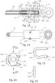
- FIGS. 1 to 8 show a first embodiment of a hydraulic line coupling 1 according to an embodiment of the invention.
- the hydraulic line coupling 1 comprises a housing 30 in which a line nozzle 20 is arranged on the left side and a line nozzle 50 on the right side.
- the two line nozzles are connected to one another in a pressure-tight manner via the pressure chamber 44 within the housing 30 with a pressure chamber housing 40 defining a pressure chamber 44.
- This has the advantage that the housing 30 does not have to be designed to be pressure-tight. It can therefore be manufactured more simply and more cost-effectively. For example, it can have a lower strength.
- materials can also be used for the housing 30 that are not necessarily corrosion-resistant to the hydraulic fluid.
- the line socket 20 has an extension 22 to which a hydraulic line 10 can be attached.
- the line socket 50 has an extension 52 to which a hydraulic line 10 can be attached.
- the hydraulic line coupling 1 connects the two hydraulic lines 10 attached to the extensions 22 and 52 respectively.
- the line connector 20 has a fastening section 23 and the line connector 50 has a fastening section 53, to each of which a sleeve 11 can be fastened to secure the corresponding hydraulic line.
- the sleeve 11 can, for example, have an internal thread that is screwed onto an external thread provided on the fastening section 23 or 53.
- Other fastening options are conceivable, such as pressing, whereby the sleeve or sleeves 11 have an undercut or can be given one by pressing, which engages in a groove on the fastening section 23 or 53.
- the line socket 20 has a passage 21 which extends through the line socket 20 from the extension 22 to the sealing area 26 provided at the opposite end.
- the extension 22 is arranged in the hydraulic line 10 and forms a pressure-tight connection with the hydraulic line 10 there.
- the line socket 20 forms a pressure-tight connection with the pressure chamber 44 at the sealing area 26 with the seal 41, which is enclosed by the pressure chamber housing 40.
- the line nozzle 20 On its outside, the line nozzle 20 has a receptacle 24 for receiving the locking device 70.
- the line socket 50 has a passage 51 that extends through the line socket 50 from the extension 52 to the sealing area 56 provided at the opposite end.
- the extension 52 is arranged in the hydraulic line 10 and forms a pressure-tight connection with the hydraulic line 10 there.
- the line socket 50 forms a pressure-tight connection with the pressure chamber 44 at the sealing area 56 with the seal 42.
- This construction creates a pressure line from the hydraulic line 10, the line socket 20, the pressure chamber 44, the line socket 50 and the hydraulic line 10, which runs inside the housing 30, which itself does not have to be pressure-tight because a pressure chamber housing 40 is provided inside the housing.
- the housing 30 serves to secure the line nozzles 20, 50 in the direction of the line run, ie the line nozzles 20, 50 are secured in the housing 30 against being pulled out.
- the line connector 50 has receptacles 54 into which a locking device 80 is pressed in order to secure the line connector 50 in the housing 30 against being pulled out.
- the housing 30 has corresponding passages 38 into which the locking devices 80 are pressed.
- Alternative fastening options to the press fit are conceivable.
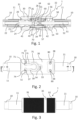
- a locking device 70 is shown.
- the line nozzle 20 has a receptacle 24 for receiving the locking device 70.
- the housing 30 has corresponding passages 37 and a receptacle 39 for the locking device 70.
- the locking device 70 can be used to secure or lock the line connector 20 after it has been inserted into the housing 30.
- the locking device 70 has two legs 71, 72 which can be inserted through passages 37 provided in the housing 30 and arranged in the corresponding receptacles 24 provided on the line connector 20.
- An arcuate receiving section 73 is provided on the leg 71 and an arcuate receiving section 74 is provided on the leg 72 for receiving the line nozzle 20 in the region of the receptacle 24, such that after inserting the legs 71, 72 of the locking device 70 in the passage 37 of the housing 30 and in the receptacle 24 of the line nozzle 20, a positive connection (in the line direction) is formed between the line nozzle 20 and the locking device 70 (receptacle 24 legs 71, 72) and a positive connection (in the line direction) between the housing 30 and the locking device 70 (passage 37 legs 71, 72), which prevents the line nozzle 20 from slipping out or being pulled out of the housing.
- a securing section 75, 76 is provided which, after insertion, engages behind the line nozzle 20 in such a way that the locking device 70 is secured against being pulled out of the receptacle 24 and the passages.
- the line nozzle 20 has a transition region 25 in which the outer diameter of the line nozzle 20 decreases from the edge of the receptacle 24 to the sealing region 26.
- the legs 71, 72 will jump into the receptacle 24 due to the elasticity of the locking device 70 because they have been spread apart by the insertion of the widening transition region 25, such that the line nozzle 20 is secured in the housing 30.
- the locking device 70 has an extension section 77 extending from the leg 71 approximately at right angles along the surface of the housing 30 and an extension section 78 extending from the leg 71 approximately at right angles along the surface of the housing 30, which are connected via a connecting section 79 are connected to one another.
- This design has the advantage that the clamping force of the locking device 70 can be increased by a quasi extension despite the relatively short legs 71, 72, so that a better and more reliable securing of the locking device 70 can be achieved.
- the receptacle 39 is designed and arranged such that the extension sections 77, 78 and the connecting section 79 can be arranged in the receptacle.
- Fig.3 shows a variant of the hydraulic line coupling 1 of Fig.1 , in which the locking device 70 is covered with an optional security device 91, which can be formed, for example, by a seal and/or a protective film and/or an overmolding, in order to detect or indicate manipulation of the locking device 70 if the security device 91 has been damaged.
- a corresponding optional security device 92 can be provided for the two locking devices 80.
- the housing 30 can, as in Fig.1 shown, be formed in one piece. It can have a first housing section 31 in which the line nozzle 20 is arranged, and a second housing section 32 in which the line nozzle 50 is arranged. Since the separate pressure chamber housing 40 is provided within the housing 30, the first housing section 31 and the second housing section 32 do not have to be connected to one another in a pressure-tight or fluid-tight manner, but can also be connected to one another with a screw connection, for example. For this purpose, in the area in which the Fig.1 shown embodiment has a recess 33 in which the inspection opening 34 is provided, a sleeve can be provided which connects a first housing part comprising the housing section 31 with a second housing part comprising the housing section 31.
- the sleeve can be arranged in a groove and screwed onto an external thread on the second housing part.
- the sleeve can be secured with a lock against twisting and thus loosening and can be overmolded after the parts are connected, for example, so that a smooth surface, as in Fig.2 shown is created.
- the hydraulic line coupling 1 can have an inspection opening 34 with which the tightness of the hydraulic line coupling 1 can be checked. Oil leaking from the inspection opening 34 indicates a leak, for example in the seal 41 or 42.
- a compressed air test can be carried out by applying compressed air to the inspection opening 34. A drop in pressure would indicate a leak in one of the two seals 41, 42, which can be caused by a defect or an incorrect position, for example.
- a valve device 60 is provided in the pressure chamber housing 40, which closes the pressure chamber housing 40 or the pressure chamber 44 to the left-hand side when the line nozzle 20 has not yet been inserted.
- the valve device 60 has a closing member 61 and a closing spring 62.
- the line nozzle has a spring holder 57 in which the closing spring 62 is received.
- the closing spring 62 pre-tensions the closing member 61 against the seal 41 arranged in the pressure chamber housing 40, so that the pressure chamber 44 is closed off from the outside in a pressure-tight manner when the line nozzle 20 has not yet been inserted into the housing 30.
- the sealing region 26 is inserted into the seal 41 and pushes the valve closing member 61 in the direction of the line nozzle 50, so that the valve device 60 opens.
- the seal 41 seals the passage 21 of the line nozzle 20 in such a way that a pressure-tight connection to the pressure chamber 44 of the pressure chamber housing 40 is created.
- Overflow channels 65 must be provided so that the hydraulic fluid can flow past the valve closing member 61.
- an engagement can be provided in the receptacle 39 such that the operator can reach under the connecting section 79 or an extension 77 or 78 with a tool or a fingernail in order to pull the locking device 70 upwards and out of the receptacles 24.
- the locking device 70 can be sealed with the safety device 91.
- the pressure chamber housing 40 can, for example, be designed as in the Figures 123 to 126 shown. Please refer to the description of the Figures 123 to 126 is referred to.
- FIGS 9 to 14 show a further embodiment of the invention, which is essentially the same as in the Figures 1 to 8 shown embodiment of the invention.
- the same reference numerals denote the same or corresponding components or features. Reference is made to the description of the other embodiments of the invention. In the following, the focus is on the differences from the other embodiments of the invention.
- the design has a valve chamber housing 140 in which the valve device 60 is arranged.
- the valve chamber housing 140 in this design is not designed as a pressure chamber housing as in the Figures 1 to 8 and 123 to 126 designed so that the hydraulic fluid can also flow past the outside of the valve chamber housing 140 when the valve device 60 is opened.
- the valve chamber housing 140 has a contact area 143 on its side facing the seal 141, with which the seal 141 can be pressed together, such that the seal 141 is pressed against the inner wall of the housing 30 and seals there. When the line nozzle 20 is inserted, the seal 141 is also pressed radially inward onto the sealing area 26, so that the seal 141 seals simultaneously to the outside and inside.
- the valve chamber housing 140 can, for example, be designed as in the Figures 127 to 130 shown. Please refer to the description of the Figures 127 to 130 is referred to.
- valve chamber housing can also be designed as a pressure chamber housing.
- the pipe connector 20 is attached to the hydraulic pipe 10 with a press sleeve 111.
- the pipe connector 20 can also be attached as in the design of Fig.1 be attached to the hydraulic line.
- the pipe socket 50 of the design of Fig.1 or Fig.9 can also be connected to the hydraulic line 10 with a press sleeve 111 corresponding to the line nozzle 20, as shown in Fig.9 shown, attached.
- the valve device 60 comprises a closing member 61 which is spherical.
- a closing member 61 which is spherical.
- overflow channels 145 are provided on the inner wall of the valve chamber housing 140.
- the optional safety device 91 can be designed smaller.
- the line nozzle is axially secured in the housing with only one locking device 80.
- two locking devices 80 or a locking device for fastening or axially securing the line nozzle 50 can be provided, which can be used to lock the locking device 70 of Fig.1 or the locking device 170 of Fig.9 corresponds.
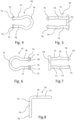
- the Figures 12 to 14 show the locking device 170 of the hydraulic line coupling of Fig.9
- the locking device 170 comprises a leg 171, which at its end comprises a securing section 175, which secures the locking device 170 against accidental withdrawal.
- the other leg 172 of the locking device 170 is straight.
- the two legs 171 and 172 are connected by a connecting section 179.
- the leg 172 of the locking device 170 can also be designed to correspond to the leg 171 and comprise a securing section corresponding to the outwardly bent securing section 175.
- the securing section(s) 175 can also be designed to be bent inwards in accordance with the locking device 70.
- Receptacles 73, 74 designed to correspond to the locking device 70 can be provided on one leg or both legs.
- FIGS 15 to 17 show a further embodiment of the invention, which is essentially the same as in the Figures 1 to 8 or 9 to 14.
- the same reference numerals denote the same or corresponding components or features. Reference is made to the description of the other embodiments of the invention. In the following, the focus is on the differences from the other embodiments of the invention.
- This embodiment has a valve chamber housing 240 which has a phase or flattening 246 on its side opposite the valve device 60.
- a web 247 interrupted in the circumferential direction can be provided in front of the flattening 246, which ensures a free cross section for hydraulic fluid flowing on the outside of the valve chamber housing.
- Overflow channels 245 are provided on the inside. Passages 248 create a connection between the outside and the inside of the valve chamber housing 240.
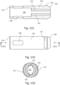
- the valve chamber housing 240 can, for example, be designed as shown in the Figures 131 to 133 shown. Please refer to the description of the Figures 131 to 133 is referred to.
- valve chamber housing can also be designed as a pressure chamber housing.
- the housing 30 is constructed in one piece and comprises a fastening section 35 on which an external thread 36 is provided for fastening the hydraulic line coupling 1 to the housing of a hydraulic component, such as the transmitter of a hydraulic clutch or a hydraulic brake.
- the pressure chamber housing 40 arranged in the housing 30 has a sealing section 43 with which the pressure chamber housing 40 can be arranged against a seal in the housing of the hydraulic component.
- the housing 30 does not have to be designed to be pressure-resistant because the pressure of the system is conducted through the pressure chamber 44 of the pressure chamber housing 40 directly into the line nozzle 20.
- the locking device 70 is different from the design of the Fig.1 rotated by 180 degrees, so that the connecting section 79 is arranged away from the pressure chamber housing or the sensor. Accordingly, the receptacle 39 is arranged to the left of the passages 37.
- the closing member 61 of the valve device 60 is similar to the closing member 61 of the embodiment of Fig.1 Alternatively, the closing element 61 can be designed according to the design of the Fig.9 be designed, wherein the pressure chamber housing 40 should then have corresponding overflow channels 45.
- the locking device 70 could be designed in accordance with the Figures 9 to 14 shown locking device 170.
- FIGS. 18 to 22 show a further embodiment of the invention, which is essentially the same as in the Figures 1 to 8 or 9 to 14 shown embodiments or in particular the embodiments shown in the Figures 15 to 17 shown embodiment of the invention.
- the same reference numerals denote the same or corresponding components or features. Reference is made to the description of the other embodiments of the invention. In the following, the focus is on the differences from the other embodiments of the invention.
- the housing 130 is formed in one piece and has a connection device 132 on the side opposite the line connector 320, which comprises a passage 131 and a ring head 132, which can be attached, for example, in a manner known to those skilled in the art to a receiver of a hydraulic bicycle disc brake with a hollow screw or a fastening screw having external hydraulic channels.
- the other side of the connection device 132 has a receptacle for receiving the valve device 60, which comprises a valve closing member 61 and a valve closing spring 62.
- the line connector 320 essentially corresponds to the line connector 20 of the Fig.1 and has a receptacle 324 for the locking device 170, a transition region 325 for spreading the locking device 170 when inserted into the housing 30 and a sealing region 326 for the seal 341 for sealing with the pressure chamber housing 340.
- the pipe connection 320 is preferably designed in accordance with the Figures 120 to 122 shown and described line socket 320 and has on its side facing the valve closing member 61 recesses 328 and intermediate webs 327 with which the line socket 320 moves the valve closing member 61 from its closed position into contact with the seal 341 in the direction of the connection device 132 when inserted.
- the sealing area 326 comes into contact with the seal 61 so that very quickly after the sealing device 60 is opened the hydraulic system or the hydraulic line coupling 1 is closed again so that as little air as possible can be introduced or hydraulic fluid can escape. Since the actuation during insertion or removal is parallel to the closing direction, very fast actuation and thus a very short time in which the hydraulic system is open can be achieved.
- a sealing section 348 is arranged between the valve chamber 344 and the line socket 320, which defines the position of the seal 341 such that the seal 341 seals between the sealing area 326 of the line socket 320 and the valve chamber housing 340.
- the valve chamber housing 340 and the sealing section 348 can be formed in two parts, with a groove for receiving the seal 341 preferably being provided in all designs.
- valve chamber housing 340 can also be similar to the pressure chamber housing 40 of Fig.1 be designed such that overflow channels are formed on the inner wall and channels for a leak test are arranged on the outside.
- the valve chamber housing can have a phase 346 according to the Figures 131 to 133 shown valve chamber housing 240.
- the locking device 170 is designed in accordance with the Figures 9 to 14 Alternatively, the locking device 170 could be designed according to the locking device shown in the Figures 1 to 8 shown locking device 70.
- FIGS. 23 to 24 show a further embodiment of the invention, which essentially corresponds to the other embodiments of the invention.
- the same reference numerals denote the same or corresponding components or features. Reference is made to the description of the other embodiments of the invention. In the following, the focus is on the differences from the other embodiments of the invention.
- FIG. 23 and 24 The execution of the Figures 23 and 24 is shown without a housing. According to the invention, it can be designed as in the other embodiments, whereby it can be attached to the fastening section 123 of the line connector 120.
- the housing can also be omitted, because the pressure chamber housing 440 is designed in such a way that the seal 441 closes the hydraulic line 10 by the valve closing member 61 when the line connector 120 is not mounted or inserted, and the seal 441 also closes the hydraulic line coupling 1 to the outside when the line connector 120 is inserted and the valve device 60 is open.
- the line connector 120 comprises a passage 121 and a ring head 122, which can be attached, for example, in a manner known to those skilled in the art to a receiver of a hydraulic bicycle disc brake with a hollow screw or a fastening screw having external hydraulic channels.
- the other side of the connection device 122 is designed in accordance with the line connector 20 of the Fig.1 and has a receptacle 124 for the locking device 170, a transition region 125 for spreading the locking device 170 when inserted into the pressure chamber housing 440 and a sealing region 126 for the seal 441 for sealing with the pressure chamber housing 440.
- the pressure chamber housing 440 has an extension with a pressing section 411 to which the hydraulic line 10 is attached.
- FIGS. 25 to 28 show further embodiments of the invention, which essentially correspond to the other embodiments of the invention.
- the same reference numerals denote the same or corresponding components or features. Reference is made to the description of the other embodiments of the invention. In the following, the focus is on the differences from the other embodiments of the invention.
- both pipe connectors 20 are in accordance with the Fig.1 shown left line socket 20 and have an over-all area 25 with which the locking device 170 can be spread open when inserting the line socket 20.
- Both locking devices 170 are designed in accordance with the locking device 170 of the Fig.9 Both locking devices 170 or one of the two locking devices 170 can alternatively also be designed in accordance with the locking device 70 of Fig.1 or one of the other locking devices.
- the Figures 25 to 26 The embodiment shown has a valve device 60 with a spherical closing element 61 corresponding Fig.9 with overflow channels on the pressure chamber housing 140 or as in Fig.9 Webs 27 can be provided on the line nozzle 20.
- the Figures 27 to 28 The embodiment shown has a valve device 60 with a closing member 61 which, according to the embodiment of the Fig.1 is formed, wherein the overflow channels are formed in the closing member 61.
- a closure device 190 is provided on the right-hand line connector 20, which can be designed, for example, as a protective cap that can be removed before the line connector 20 is inserted into the housing.
- the closure device 190 prevents hydraulic fluid from escaping, for example during transport or storage.
- a locking device 191 is provided on the closure device 190 in order to prevent incorrect insertion of the line connector 20 with the closure device 190 attached.
- the locking device 191 can be designed, for example, as a bead whose dimensions or cross-section are so large that it cannot be inserted into the housing 30.
- a receptacle 192 is provided into which, for example, a wire or another tool can be inserted with which the hydraulic line can be guided, for example, through a frame part for laying or assembly.
- FIGS. 29 to 31 show a further embodiment of the invention, which essentially corresponds to the other embodiments of the invention.
- the same reference numerals denote the same or corresponding components or features. Reference is made to the description of the other embodiments of the invention. In the following, the focus is on the differences from the other embodiments of the invention.
- a pressure chamber housing 440 is provided, which is designed according to the design of the Figures 23 and 24 In the recess 54 of the right pipe connection 50, a locking device corresponding to the locking device 80 of Fig.1 arranged and/or a seal 442 according to the design of Fig. 23 be arranged.
- the left hydraulic line (not shown) can be fastened with a press sleeve 111 to the left line socket 820 at the fastening section 823, which is arranged between the sealing section 826 and the extension 822.
- the valve closing member 61 can have passages 611 as shown in order to ensure a hydraulic connection between the two line nozzles 50 and 820 when the valve device 60 is open.
- a housing 30 can be arranged around the pressure chamber housing 440, which can, for example, engage in the recesses provided in the region of the valve device 60 on the pressure housing 440.
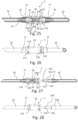
- FIGS. 32 to 35 show a further embodiment of the invention, which essentially corresponds to the other embodiments of the invention.
- the same reference numerals denote the same or corresponding components or features. Reference is made to the description of the other embodiments of the invention. In the following, the focus is on the differences from the other embodiments of the invention.
- the locking device 270 comprises two legs 271 and 272, which are connected to a connecting section 279. At the ends of the legs 271, 272, securing sections 275, 276 are provided, which engage behind the corresponding line connector 20, 50 after insertion so that the locking device is secured against removal.
- the legs 271, 272 have receiving sections 273, 274 in the middle for receiving the line connectors 20, 50 in the area of the receptacles 24, 54, in which the legs 271, 272 are arranged.
- Fig. 32 shows the hydraulic line coupling in a state in which the line nozzle is only partially inserted into the housing 140, such that the valve device 60 is not yet actuated, so that the valve closing member rests against the seal 141.
- FIGS. 36 to 37 show a further embodiment of the invention, which essentially corresponds to the other embodiments of the invention.
- the same reference numerals denote the same or corresponding components or features. Reference is made to the description of the other embodiments of the invention. In the following, the focus is on the differences from the other embodiments of the invention.
- a master device 2 which can be, for example, the master device of a hydraulic bicycle brake.
- the master device 2 comprises a housing 230 in which a pressure chamber housing 40 is arranged, which is sealed to the line connector 220 with a seal 41.
- the pipe connection 220 is provided with a locking device 70 according to the design of Fig.1 secured in a form-fitting manner to the housing 230.
- the line nozzle 220 is constructed in two parts and comprises a part with the extension 222, which is fastened to the line nozzle 220 with a press sleeve 111.
- the line nozzle comprises a fastening section 223 with an internal thread, into which a press sleeve 211 is screwed, which has a corresponding external thread on a fastening section 213.
- the hydraulic line coupling further comprises a locking device 290 with which the line connector 220 can be secured in the housing.
- the locking device 290 can be designed as a rotary lock similar to a bayonet lock, which for example has two extensions that can be rotated under a corresponding clamping device 231 in order to secure or lock the locking device 240 to the housing 230 in order to prevent unintentional release.
- the closure device 290 is arranged and designed such that it simultaneously serves as a support or securing means for the seal 41, for example in that the end of the closure device 290 defines one side of a groove in which the seal 41 is received.
- the closure device 290 is arranged in the housing so as to be rotatable that it can be rotated by approximately 90 degrees into a release position in which the locking device 70 can be removed from the line socket or the line socket 220 can be removed from the housing 230 so that the hydraulic line 10 can be separated from or connected to the housing 230.
- the locking device 290 can be designed in accordance with the Figures 90 to 92 shown closure device 290.
- FIGS. 38 to 41 show a further embodiment of the invention, which essentially corresponds to the other embodiments of the invention.
- the same reference numerals denote the same or corresponding components or features. Reference is made to the description of the other embodiments of the invention. In the following, the focus is on the differences from the other embodiments of the invention.
- the Figures 38 to 41 The design shown has two hydraulic line couplings 1, which correspond to the design of Fig.1 are designed.
- the respective line connectors 20 can be secured relative to the housing 30 by arranging locking devices 70 in the receptacles 24, ie via an indirect positive connection which is designed as described above.
- the respective line connectors 50 can also be secured via locking devices 80 which engage in the receptacles 54.
- the two hydraulic line couplings are arranged in a common housing 30.
- the housing 230 has a clamping device 280 which is secured to the housing with a securing device 281, which can comprise a securing bracket, for example.
- the clamping device 280 has a wedge which can be clamped with a tensioning device 282 in such a way that the housing can be clamped in a pipe with the clamping device.
- the clamping device 280 or the housing 30 with the clamping device 280 can have a dual function if the housing 30 is arranged in a handlebar tube 4 that is to be clamped against a frame tube of the vehicle.
- the clamping device 280 can clamp the handlebar tube 4 against the frame tube and at the same time the housing 30 or the hydraulic line couplings 1 can be clamped against the handlebar tube 4.
- the clamping device 282 can comprise a threaded hole 283 in the housing 30 into which a threaded screw 285 can be screwed for fastening in a handlebar tube 4. When screwing into the threaded hole, the clamping device 280 slides radially outwards due to the wedge-like ramp and clamps the housing 30 in the handlebar shaft tube 4.
- An adjustment device 284 is provided in the housing 30, with which the clamping device 280 can be fixed in the tube in order to be able to adapt the claw function of the clamping device 280 to different diameters of the handlebar shaft tube.
- the clamping device which in the embodiment shown is designed as a wedge, can be adjusted radially outwards or inwards so that it can be adapted to the diameter of the tube in which the housing 30 is clamped.
- the clamping device 282 can be tightened, for example by means of a clamping screw 285 which is inserted into the threaded hole 283.
- valve chamber housing 340 essentially corresponds to the valve chamber housing of Fig. 18 , whereby this can be sealed against the housing 30 by a further seal 341 corresponding to the seal 342.
- FIGS. 42 to 45 show a further embodiment of the invention, which essentially corresponds to the other embodiments of the invention.
- the same reference numerals denote the same or corresponding components or features. Reference is made to the description of the other embodiments of the invention. In the following, the focus is on the differences from the other embodiments of the invention.
- FIGS. 46 to 50 show a further embodiment of the invention, which essentially corresponds to the other embodiments of the invention.
- the same reference numerals denote the same or corresponding components or features. Reference is made to the description of the other embodiments of the invention. In the following, the focus is on the differences from the other embodiments of the invention.
- the execution of the Figures 46 to 50 essentially corresponds to the statements of the Figures 38 to 41 or 42 to 45, but has other locking devices 370.
- the locking devices 370 comprise locking members 372, which can be designed, for example, as balls that are arranged in a rotating cap 371 in such a way that the balls move between radially inward and radially outward positions when the rotating cap 371 is rotated.
- the balls can be brought into a position in which they clamp the line connectors 20 by being inserted into corresponding receptacles.
- the rotating caps 371 can be rotated in the other direction so that the balls are arranged radially further outward so that the corresponding line connector 20 can be removed from the housing 30.
- the locking devices 370 can, for example, be designed according to the Fig. 98 or in Fig. 111 shown locking devices 370.
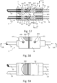
- FIGS. 51 to 52 show a further embodiment of the invention, which essentially corresponds to the other embodiments of the invention.
- the same reference numerals denote the same or corresponding components or features. Reference is made to the description of the other embodiments of the invention. In the following, the focus is on the differences from the other embodiments of the invention.
- the pipe socket 220 of the execution of the Figures 51 to 52 corresponds essentially to the line connector 220 of the embodiment of Figures 365 to 37.
- the housing 30 with two hydraulic line couplings 1 is arranged in the handlebar tube 4.
- the clamping device 280 can be actuated by means of the clamping screw 285 shown in order to clamp the housing 30 against the inner wall of the handlebar shaft 4.
- a passage 6 is provided on the housing 30 through which, for example, cables for signal transmission or for lighting devices can be guided.
- the two pressure chamber housings 440 of the two hydraulic line couplings 1 can, for example, be designed according to the design of the Fig. 29 be trained.
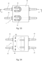
- FIGS. 53 to 56 show a further embodiment of the invention, which essentially corresponds to the other embodiments of the invention.
- the same reference numerals denote the same or corresponding components or features. Reference is made to the description of the other embodiments of the invention. In the following, the focus is on the differences from the other embodiments of the invention.
- the execution of the Figures 53 to 56 has a common housing 30 in which two hydraulic line couplings 1 are provided. These each have a line nozzle 20 which is provided with a locking device 70 according to the Figures 4 to 8 secured in the housing, and a line connector 50 which is secured in the housing with locking devices 80.
- the housing can be wedged in a handlebar tube 4 and has a passage 6 for the laying of electrical cables. Between the line connectors 20 and 50, a pressure chamber 44 is provided which is enclosed by a pressure chamber housing 40.
- the two pressure chamber housings 40 of the two hydraulic line couplings 1 can, for example, be designed according to the design of the Fig.1 be trained.
- the execution of the Figures 57 to 61 essentially corresponds to the statements of the Figures 38 to 41 or 42 to 45, but has other locking devices 470.
- the locking device 470 comprises a pin 471 which simultaneously secures both line connectors 20 of the two hydraulic line couplings 1, which are arranged in a common housing 30.
- the pin 471 is arranged in corresponding receptacles 24 on the line connectors 20 and is also arranged in a passage 37 in the housing 30.
- the two line nozzles 50 of the two hydraulic line couplings 1 are also secured with a corresponding common locking device 470, which comprises a pin 471.
- the pin 471 is arranged in corresponding receptacles 54 on the line nozzles 50 and is also arranged in a passage 37 in the housing 30.
- the two pressure chamber housings 340 of the two hydraulic line couplings 1 can, for example, be designed according to the design of the Fig. 18 be trained.
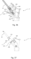
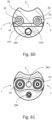
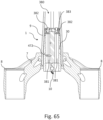
- FIGS. 62 to 65 show a further embodiment of the invention, which essentially corresponds to the other embodiments of the invention.
- the same reference numerals denote the same or corresponding components or features. Reference is made to the description of the other embodiments of the invention. In the following, the focus is on the differences from the other embodiments of the invention.
- no clamping device 280 When executing the Figures 62 to 65 no clamping device 280 is provided.
- the two line nozzles 50 of the two hydraulic line couplings 1, which are provided in a common housing 30, are secured in the housing 30 by a common locking device 470, which comprises a pin 471.
- the two line nozzles 20 can be secured by a locking device that can be arranged in a receptacle 472 that is provided in the housing 30.
- Fig. 65 shows how the hydraulic line coupling of Fig. 62 in a fork bridge 7 that connects two fork legs 8, or in the shaft 9 that extends from the fork bridge 7 in the direction of the handlebars and can be connected to the handlebar shaft 6.
- a clamping device 380 is provided that includes two clamping screws 382 that can tension a spring device 383 against the inner wall of the shaft 9.
- passages 381 are provided in the housing, into which a suitable tool can engage.
- the two pressure chamber housings 340 of the two hydraulic line couplings 1 can, for example, be designed according to the design of the Fig. 18 be trained.
- FIGS. 66 to 68 show a further embodiment of the invention, which essentially corresponds to the other embodiments of the invention.
- the same reference numerals denote the same or corresponding components or features. Reference is made to the description of the other embodiments of the invention. In the following, the focus is on the differences from the other embodiments of the invention.
- the execution of the Figures 66 to 68 essentially corresponds to the execution of the Figures 46 to 50 , which is arranged in a handlebar tube 5.
- the housing 30 is attached to the handlebar tube 5.
- two Hydraulic line couplings 1 are provided in the housing 30, two Hydraulic line couplings 1 are provided. These each have an angled line connector 150 with an angled section 151 that changes the direction of the hydraulic line by approximately 90 degrees, such that the hydraulic line can run in the handlebar tube 5.
- the angled line connector 150 has a line nozzle receptacle 152 at its end, to which a line nozzle can be attached for connection to a hydraulic line 10.
- the two pressure chamber housings 640 of the two hydraulic line couplings 1 can, for example, correspond to the pressure chamber housings 540 of the Fig. 46 be trained.
- the housing 30 has a flange 480 with which it can be flanged to the handlebar tube 5 in a manner known to those skilled in the art.
- the locking devices 370 can, for example, be designed according to the Fig. 98 or in Fig. 111 shown locking devices 370.
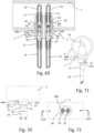
- FIGS. 69 to 72 show a further embodiment of the invention, which essentially corresponds to the other embodiments of the invention.
- the same reference numerals denote the same or corresponding components or features. Reference is made to the description of the other embodiments of the invention. In the following, the focus is on the differences from the other embodiments of the invention.
- the execution of the Figures 69 to 72 essentially corresponds to the execution of the Figures 1 to 8 , wherein 2 hydraulic line couplings 1 are provided in a common housing 30, which is arranged on a handlebar tube 5.
- the hydraulic lines 10 are led into the handlebar tube 5 and can be led out of the handlebar tube 5 on the other side or can be laid in the handlebar tube 5 by bending the hydraulic line.
- the housing 30 has a flange 480 with which it can be supported on the handlebar tube 5.
- the two line nozzles 20 are secured to the housing 30 with a common locking device 470, which comprises a pin 471, which is guided through passages 37 in the housing 30.
- the two line nozzles 50 are arranged in the respective pressure chamber housings 40 with a press fit. Alternatively, they can also be arranged as in the embodiment of Fig.1 each secured with a locking device 80 and/or a common locking device in the housing.
- the two pressure chamber housings 440 of the two hydraulic line couplings 1 can, for example, correspond to the pressure chamber housings 440 of the Fig. 23 be trained.
- the execution of the Figures 73 to 76 essentially corresponds to the execution of the Figures 69 to 72
- the housing 30 is arranged essentially outside the handlebar tube 5.
- a A clamping screw 485 is provided with which the housing 30 can be attached to the handlebar tube.
- the lower lines 10 are attached to the line sockets 20 with press sleeves.
- the hydraulic lines can also be connected to the Figures 69 to 72 with a sleeve that engages a fastening section 23 of the pipe connectors 20.
- the pipe connectors 20 are provided with locking devices 80 corresponding to the design of Fig.1 individually secured in the housing 30.
- the other described variants with the locking devices 70, 170 etc. are also conceivable for securing the line nozzles 20 in the housing 30.
- the two pressure chamber housings 440 of the two hydraulic line couplings 1 can, for example, correspond to the pressure chamber housings 440 of the Fig. 23 or the pressure chamber housing 640 of the Fig. 66 be trained.
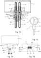
- FIGS 77 to 78 show a further embodiment of the invention, which essentially corresponds to the other embodiments of the invention.
- the same reference numerals denote the same or corresponding components or features. Reference is made to the description of the other embodiments of the invention. In the following, the focus is on the differences from the other embodiments of the invention.
- the two pressure chamber housings 740 are essentially like the pressure chamber housing 440 of the Fig. 23 but is bent by 90 degrees.
- a valve closing spring 62 of the valve device 60 is arranged in the bent section. This design has the advantage of being extremely short.
- the housing 30 has a flange 480 and is attached to the handlebar tube 5 with a clamping screw 485 such that the hydraulic lines 10 are guided into the handlebar stem 3.
- the hydraulic lines 10, which exit in the handlebar stem 3, are fastened with press sleeves 111.
- line nozzles 20 can be provided or designed for these hydraulic lines 10 in accordance with the other designs.
- the execution of the Figures 79 to 81 essentially corresponds to the execution of the Figures 66 to 68
- the housing 30 is made smaller, so that the pressure chamber housing 40 extends outside the housing 30, ie both outside and inside the handlebar tube 5.
- the line nozzles 20 are each secured outside the handlebar tube 5 with locking devices 170 in the pressure chamber housing 40. It would also be conceivable to use the locking devices 70 in accordance with the Figures 4 to 8 , in which case recesses should preferably be provided on the pressure chamber housing 40 for receiving the extensions 77, 78 and the connecting section 79.
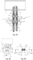
- FIGS. 82 to 84 show a further embodiment of the invention, which essentially corresponds to the other embodiments of the invention.
- the same reference numerals denote the same or corresponding components or features. Reference is made to the description of the other embodiments of the invention. In the following, the focus is on the differences from the other embodiments of the invention.
- the execution of the Figures 82 to 84 comprises two hydraulic line couplings 1, which are designed according to the Fig. 25
- the lines 10 are introduced into a handlebar tube 5 via a common flange 485.
- the two hydraulic line couplings 1 of the two valve chamber housings 140 can, for example, be designed as in the Figures 127 to 130 shown be trained.
- FIGS. 85 to 87 show a further embodiment of the invention, which essentially corresponds to the other embodiments of the invention.
- the same reference numerals denote the same or corresponding components or features. Reference is made to the description of the other embodiments of the invention. In the following, the focus is on the differences from the other embodiments of the invention.
- the execution of the Figures 85 to 87 comprises two hydraulic line couplings 1, which are designed according to the Fig.1 but are arranged in a common housing 30.
- the housing 30 comprises a flange 480 with which it is supported on the handlebar tube.
- the hydraulic lines 10 are in the Figures 85 to 87 not shown and can be changed according to the design of Fig.1 be attached to the pipe sockets 20 or 50.
- the Figures 90 to 92 show a possible design of the closure device 290.
- the closure device 290 comprises a cylindrical region around which the closure device is arranged so as to be rotatable in the transmitter device 2.
- Two passages 293 are provided in the cylindrical region, wherein the locking device 70 is inserted into a passage with one leg 71, 72 in each case when inserted into the locked closure device 290, such that the web lying between them is arranged between the two legs 71, 72 of the locking device 70.
- a stop 294 is provided with which the valve device 60 or the pressure chamber housing 40 can be secured in the transmitter device 2.
- the closure device 290 has a flange 292 which has two opposite extensions 291.
- the pipe connection 320 can be adjusted according to Figures 120 to 122 wherein the line nozzle 320 can have recesses 328 between webs 327 at its tip in order to ensure a secure hydraulic connection between the two line nozzles of the hydraulic line coupling.
- FIGS. 100 to 104 show a further embodiment of the invention, which essentially corresponds to the other embodiments of the invention.
- the same reference numerals denote the same or corresponding components or features. Reference is made to the description of the other embodiments of the invention. In the following, the focus is on the differences from the other embodiments of the invention.
- the execution of the Figures 100 to 104 essentially corresponds to the execution of the Figures 1 to 8 , whereby only one locking device 80 is provided.
- FIGS 105 to 107 show a further embodiment of the invention, which essentially corresponds to the other embodiments of the invention.
- the same reference numerals denote the same or corresponding components or features. Reference is made to the description of the other embodiments of the invention. In the following, the focus is on the differences from the other embodiments of the invention.
- the execution of the Figures 105 to 107 essentially corresponds to the execution of the Figures 23 to 24 , wherein a housing 330 is also shown.
- the housing 330 has two closure sections 331, 332 at which it can be connected to one another, for example via a snap connection and/or a self-locking, non-detachable connection.
- the two hydraulic line couplings 1 of the two valve chamber housings 440 can, for example, be arranged as shown in the Fig. 23 shown.
- the housing 330 can have a projection 570 on its inner side, with which the housing 330 engages in a corresponding recess 124 provided on the connection device 120.
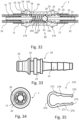
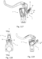
- FIGS. 112 to 119 show a further embodiment of the invention, which essentially corresponds to the other embodiments of the invention.
- the same reference numerals denote the same or corresponding components or features. Reference is made to the description of the other embodiments of the invention. In the following, the focus is on the differences from the other embodiments of the invention.
- the execution of the Figures 112 to 119 essentially corresponds to the execution of the Figures 36 to 37 .
- the pressure chamber housing is not provided as a separate component, but is integrated directly into the transmitter device 2.
- the closure device 290 can secure the valve device 60 in the transmitter device 2.
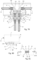
- the Figures 120 to 122 show a possible design of a line nozzle 320, which has recesses 328 between webs 327 at its tip in order to ensure a secure hydraulic connection.
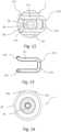
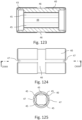
- the Figures 123 to 126 show a possible design of the pressure chamber housing 40.
- the pressure chamber housing 40 has overflow channels on its inside to ensure a secure hydraulic connection. Channels 46, 47 are provided on its outside. These are used to check the tightness or correct positioning of the seals 41 and 42 with a pressure test.
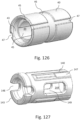
- the Figures 127 to 130 show a possible design of the valve chamber housing 140.
- the valve chamber housing 140 has webs 147 and passages 148, 149 on its outside to ensure a secure hydraulic connection.
- the Figures 131 to 133 show a possible design of the valve chamber housing 240.
- the valve chamber housing 240 has channels 245 on its inside to ensure a secure hydraulic connection.
- the valve chamber housing 240 has webs 247 and passages 248 on its outside to ensure a secure hydraulic connection.
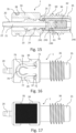
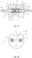
- the Figures 134 to 138 show the process steps for coupling the hydraulic line 10 to a housing 30 as an example of an embodiment which essentially corresponds to the embodiment of the Figures 15 to 17 , wherein additionally a press sleeve 12 is provided and a protective cap 13 is shown.
- the locking device 570 is pressed into the housing 30 in such a way that the line connector 20 is secured in the housing 30.
- the locking device 570 has a press sleeve 571, which engages with an engagement device 572 in a receptacle 24 provided on the line connector 20.
- the press sleeve 571 also has a latching device 573, which, after being pressed in, latches into a corresponding receptacle 304 provided in the housing 30 and secures the press sleeve 570 in the housing 30 via a positive connection.
- the line connector 20 is in turn fixed in the line connector 20 by the positive connection between the engagement device 572 and the receptacle 24.
- the sequence of the arrangement of the hydraulic line 10 with the line nozzle 20 and the press sleeve 571 in the Housing 30 shows that the valve device 60 is closed for a very long time, as in Fig. 135 shown, and is only opened before final pressing, as shown in Fig. 136 shown. Immediately afterwards, the connection to the outside is closed again by the engagement of the line nozzle 20 with the sealing area 26 in the seal 241, so that only very little air can penetrate or very little hydraulic fluid can escape.
Landscapes
- Engineering & Computer Science (AREA)
- General Engineering & Computer Science (AREA)
- Mechanical Engineering (AREA)
- Transportation (AREA)
- Physics & Mathematics (AREA)
- Fluid Mechanics (AREA)
- Quick-Acting Or Multi-Walled Pipe Joints (AREA)
- Hydraulic Clutches, Magnetic Clutches, Fluid Clutches, And Fluid Joints (AREA)
- Transmission Of Braking Force In Braking Systems (AREA)
- Valves And Accessory Devices For Braking Systems (AREA)
Applications Claiming Priority (2)
| Application Number | Priority Date | Filing Date | Title |
|---|---|---|---|
| DE102019208066.9A DE102019208066A1 (de) | 2019-06-03 | 2019-06-03 | Hydraulikleitungskupplung, insbesondere für eine hydraulische Bremse oder Kupplung lenkergeführter Fahrzeuge und hydraulische Bremse eines lenkergeführten Fahrzeuges |
| EP20177708.3A EP3756961B1 (fr) | 2019-06-03 | 2020-06-01 | Accouplement de conduite hydraulique, en particulier pour un frein ou embrayage hydraulique d'un véhicule dirigé par guidon |
Related Parent Applications (1)
| Application Number | Title | Priority Date | Filing Date |
|---|---|---|---|
| EP20177708.3A Division EP3756961B1 (fr) | 2019-06-03 | 2020-06-01 | Accouplement de conduite hydraulique, en particulier pour un frein ou embrayage hydraulique d'un véhicule dirigé par guidon |
Publications (2)
| Publication Number | Publication Date |
|---|---|
| EP4407224A2 true EP4407224A2 (fr) | 2024-07-31 |
| EP4407224A3 EP4407224A3 (fr) | 2024-08-07 |
Family
ID=70975726
Family Applications (2)
| Application Number | Title | Priority Date | Filing Date |
|---|---|---|---|
| EP20177708.3A Active EP3756961B1 (fr) | 2019-06-03 | 2020-06-01 | Accouplement de conduite hydraulique, en particulier pour un frein ou embrayage hydraulique d'un véhicule dirigé par guidon |
| EP23214322.2A Pending EP4407224A3 (fr) | 2019-06-03 | 2020-06-01 | Accouplement de conduite hydraulique, en particulier pour un frein ou embrayage hydraulique d'un véhicule dirigé par guidon |
Family Applications Before (1)
| Application Number | Title | Priority Date | Filing Date |
|---|---|---|---|
| EP20177708.3A Active EP3756961B1 (fr) | 2019-06-03 | 2020-06-01 | Accouplement de conduite hydraulique, en particulier pour un frein ou embrayage hydraulique d'un véhicule dirigé par guidon |
Country Status (4)
| Country | Link |
|---|---|
| US (1) | US11802644B2 (fr) |
| EP (2) | EP3756961B1 (fr) |
| DE (1) | DE102019208066A1 (fr) |
| TW (1) | TWI874404B (fr) |
Families Citing this family (7)
| Publication number | Priority date | Publication date | Assignee | Title |
|---|---|---|---|---|
| EP4182592A4 (fr) * | 2020-07-20 | 2024-06-12 | Norma U.S. Holding LLC | Raccord rapide de conduite de fluide à clapet anti-retour |
| US11821558B2 (en) * | 2021-09-08 | 2023-11-21 | Cooper-Standard Automotive Inc. | Fluid connector with dry break |
| US20230288000A1 (en) * | 2022-03-08 | 2023-09-14 | CoollT Systems, Inc. | Moldable fluid couplers and related fluid connectors, systems and methods |
| CN114636028B (zh) * | 2022-03-21 | 2025-04-11 | 湖北飞歌科技股份有限公司 | 用于水利工程的管道连接与支撑装置 |
| DE102022207379A1 (de) | 2022-07-19 | 2024-01-25 | Gustav Magenwirth Gmbh & Co. Kg | Gebervorrichtung für eine hydraulische Bremse lenkergeführter Fahrzeuge und hydraulische Bremse für ein lenkergeführtes Fahrzeug |
| DE102023201538A1 (de) * | 2022-11-16 | 2024-05-16 | Continental Automotive Technologies GmbH | Verbindungsanordnung zum Anschluss einer hydraulischen Fluidleitung an eine hydraulische Vorrichtung eines Kraftfahrzeugs |
| TWI897498B (zh) * | 2024-06-27 | 2025-09-11 | 富世達股份有限公司 | 按壓式管接頭鎖定結構 |
Citations (4)
| Publication number | Priority date | Publication date | Assignee | Title |
|---|---|---|---|---|
| EP1514758A1 (fr) | 2003-09-12 | 2005-03-16 | Formula S.r.L. | Dispositif de raccordement d' un étrier de frein et une pompe pour des freins hydrauliques |
| CN201330906Y (zh) | 2009-01-08 | 2009-10-21 | 郭黄民 | 快速接头 |
| EP2431647B1 (fr) | 2010-09-16 | 2014-08-27 | Formula S.A.S. di "Formula Group S.R.L." & C. | Montage hydraulique pour tuyaux |
| DE102015106236A1 (de) | 2014-09-19 | 2016-03-24 | Yuan-Hung WEN | Schnell lösbarer Verbinder |
Family Cites Families (9)
| Publication number | Priority date | Publication date | Assignee | Title |
|---|---|---|---|---|
| US3567175A (en) * | 1968-10-08 | 1971-03-02 | Stile Craft Mfg Inc | Quick release coupling |
| DE2617620A1 (de) * | 1976-04-22 | 1977-11-03 | Klein Rectus App | Schnellkupplung, insbesondere selbstabsperrende schnellkupplung |
| US5150880A (en) * | 1991-02-14 | 1992-09-29 | Austin Jr George K | Valve assembly with flow control |
| US5253842A (en) * | 1992-07-30 | 1993-10-19 | Lab Products, Inc. | Quick disconnect water valve assembly |
| DE19715899B4 (de) * | 1997-04-16 | 2004-09-02 | Voss Automotive Gmbh | Steckkupplung mit Auslaufschutz |
| US20080129045A1 (en) * | 2001-12-25 | 2008-06-05 | Mirai Industry Co., Ltd. | Water pipe end structure and connection therefor |
| TWM466864U (zh) | 2013-02-08 | 2013-12-01 | Tektro Technology Corp | 管體快拆接頭結構 |
| US9827968B2 (en) | 2015-01-12 | 2017-11-28 | Sram, Llc | Hydraulic bicycle system |
| DE102017211793A1 (de) * | 2017-07-10 | 2019-01-10 | Gustav Magenwirth Gmbh & Co. Kg | Hydraulikleitungsanschluss für eine hydraulische Bremse lenkergeführter Fahrzeuge, Hydraulikleitungsanschluss- und Hydraulikkomponentenbefestigungsvorrichtung für eine hydraulische Betätigungsvorrichtung lenkergeführter Fahrzeuge, Lenkeranordnung für ein lenkergeführtes Fahrzeug und hydraulische Bremse für ein lenkergeführtes Fahrzeug |
-
2019
- 2019-06-03 DE DE102019208066.9A patent/DE102019208066A1/de not_active Withdrawn
-
2020
- 2020-06-01 EP EP20177708.3A patent/EP3756961B1/fr active Active
- 2020-06-01 EP EP23214322.2A patent/EP4407224A3/fr active Pending
- 2020-06-02 TW TW109118521A patent/TWI874404B/zh active
- 2020-06-03 US US16/891,430 patent/US11802644B2/en active Active
Patent Citations (4)
| Publication number | Priority date | Publication date | Assignee | Title |
|---|---|---|---|---|
| EP1514758A1 (fr) | 2003-09-12 | 2005-03-16 | Formula S.r.L. | Dispositif de raccordement d' un étrier de frein et une pompe pour des freins hydrauliques |
| CN201330906Y (zh) | 2009-01-08 | 2009-10-21 | 郭黄民 | 快速接头 |
| EP2431647B1 (fr) | 2010-09-16 | 2014-08-27 | Formula S.A.S. di "Formula Group S.R.L." & C. | Montage hydraulique pour tuyaux |
| DE102015106236A1 (de) | 2014-09-19 | 2016-03-24 | Yuan-Hung WEN | Schnell lösbarer Verbinder |
Also Published As
| Publication number | Publication date |
|---|---|
| US20200378539A1 (en) | 2020-12-03 |
| EP4407224A3 (fr) | 2024-08-07 |
| EP3756961A3 (fr) | 2021-04-28 |
| US11802644B2 (en) | 2023-10-31 |
| TWI874404B (zh) | 2025-03-01 |
| EP3756961A2 (fr) | 2020-12-30 |
| DE102019208066A1 (de) | 2020-12-03 |
| TW202107000A (zh) | 2021-02-16 |
| EP3756961B1 (fr) | 2023-12-06 |
Similar Documents
| Publication | Publication Date | Title |
|---|---|---|
| EP3756961B1 (fr) | Accouplement de conduite hydraulique, en particulier pour un frein ou embrayage hydraulique d'un véhicule dirigé par guidon | |
| DE69634011T2 (de) | Verbindungsherstellung und herstellungsverfahren | |
| DE4002057C2 (fr) | ||
| DE69611725T2 (de) | Hochdruckschnellkupplung zur verwendung in fahrzeugbremsen | |
| DE112008003080B4 (de) | Schlauchleitungsverbinder sowie Leitungssatz | |
| WO2018069384A1 (fr) | Connecteur, module de connecteur et procédé permettant de produire un connecteur | |
| DE60205641T2 (de) | Zur verbindung zweier röhrenförmiger elemente verwendete kupplung und montageverfahren dafür | |
| EP0545037B1 (fr) | Dispositif d'accouplement de deux conduites, en particulier pour des conduites de carburant | |
| DE3416702C2 (de) | Schlaucharmatur | |
| DE69521428T2 (de) | Rohrverbindung für aussergewöhnliche gebrauchsbedingungen | |
| DE29610385U1 (de) | Steckkupplung für Rohre | |
| DE4035453A1 (de) | Schnellverschlusskupplung fuer hydraulische bremssysteme, insbesondere anhaengerkupplungen | |
| EP3980304A1 (fr) | Dispositif d'accouplement conçu pour un système hydraulique et procédé pour accoupler et relier par écoulement un premier et un deuxième élément d'accouplement du dispositif d'accouplement | |
| EP2199652B1 (fr) | Dispositif de connexion étanche et de fixation d'une conduite de fluide dotée d'un autre composant conduisant du liquide | |
| EP1770320B1 (fr) | Raccord détachable à fiche pour des tuyaux | |
| DE19808315A1 (de) | Nehmerzylinder mit einem Druckstutzen, an den ein Adapter anschließbar ist, der durch eine Öffnung des Kupplungsgehäuses einführbar ist | |
| DE102010010315B4 (de) | Ventilanschlussarmatur, Ventiladapterelement, Einsatzelement und Verfahren zum Einpressen eines Einsatzelements | |
| DE102013223754A1 (de) | Entlüftungseinrichtung für ein hydraulisches System | |
| EP1963169A2 (fr) | Pièce de raccordement et étrier de frein | |
| EP1026432B1 (fr) | Dispositif de raccordement pour tuyaux | |
| DE102008053380A1 (de) | Verbindung | |
| DE102021132893B3 (de) | Verbindungssystem zum Verbinden einer Fluidleitung mit einem Fluidsystem | |
| DE2634721A1 (de) | Hydraulisches dreiwegeventil, insbesondere wasseranschluss fuer mund- und/ oder hautmassage- bzw. hautreinigungsduschen | |
| DE102016223744B4 (de) | Bremssystem mit einem Verbindungselement | |
| EP1493957B1 (fr) | Raccord à vis entre boîte et élément de jonction |
Legal Events
| Date | Code | Title | Description |
|---|---|---|---|
| PUAI | Public reference made under article 153(3) epc to a published international application that has entered the european phase |
Free format text: ORIGINAL CODE: 0009012 |
|
| STAA | Information on the status of an ep patent application or granted ep patent |
Free format text: STATUS: THE APPLICATION HAS BEEN PUBLISHED |
|
| REG | Reference to a national code |
Ref country code: DE Ref legal event code: R079 Free format text: PREVIOUS MAIN CLASS: F16L0037407000 Ipc: B60T0017040000 |
|
| PUAL | Search report despatched |
Free format text: ORIGINAL CODE: 0009013 |
|
| AC | Divisional application: reference to earlier application |
Ref document number: 3756961 Country of ref document: EP Kind code of ref document: P |
|
| AK | Designated contracting states |
Kind code of ref document: A2 Designated state(s): AL AT BE BG CH CY CZ DE DK EE ES FI FR GB GR HR HU IE IS IT LI LT LU LV MC MK MT NL NO PL PT RO RS SE SI SK SM TR |
|
| AK | Designated contracting states |
Kind code of ref document: A3 Designated state(s): AL AT BE BG CH CY CZ DE DK EE ES FI FR GB GR HR HU IE IS IT LI LT LU LV MC MK MT NL NO PL PT RO RS SE SI SK SM TR |
|
| RIC1 | Information provided on ipc code assigned before grant |
Ipc: F16L 37/407 20060101ALI20240701BHEP Ipc: F16L 37/40 20060101ALI20240701BHEP Ipc: B60T 17/04 20060101AFI20240701BHEP |
|
| STAA | Information on the status of an ep patent application or granted ep patent |
Free format text: STATUS: REQUEST FOR EXAMINATION WAS MADE |
|
| 17P | Request for examination filed |
Effective date: 20250130 |