EP4406902A1 - Vorrichtung und verfahren zur steuerung eines fahrtreppensystems oder eines fahrsteigsystems - Google Patents
Vorrichtung und verfahren zur steuerung eines fahrtreppensystems oder eines fahrsteigsystems Download PDFInfo
- Publication number
- EP4406902A1 EP4406902A1 EP24150678.1A EP24150678A EP4406902A1 EP 4406902 A1 EP4406902 A1 EP 4406902A1 EP 24150678 A EP24150678 A EP 24150678A EP 4406902 A1 EP4406902 A1 EP 4406902A1
- Authority
- EP
- European Patent Office
- Prior art keywords
- moving walkway
- determining
- threshold
- value
- load value
- Prior art date
- Legal status (The legal status is an assumption and is not a legal conclusion. Google has not performed a legal analysis and makes no representation as to the accuracy of the status listed.)
- Pending
Links
Images

Classifications
-
- B—PERFORMING OPERATIONS; TRANSPORTING
- B66—HOISTING; LIFTING; HAULING
- B66B—ELEVATORS; ESCALATORS OR MOVING WALKWAYS
- B66B25/00—Control of escalators or moving walkways
- B66B25/003—Methods or algorithms therefor
-
- B—PERFORMING OPERATIONS; TRANSPORTING
- B66—HOISTING; LIFTING; HAULING
- B66B—ELEVATORS; ESCALATORS OR MOVING WALKWAYS
- B66B25/00—Control of escalators or moving walkways
-
- B—PERFORMING OPERATIONS; TRANSPORTING
- B66—HOISTING; LIFTING; HAULING
- B66B—ELEVATORS; ESCALATORS OR MOVING WALKWAYS
- B66B23/00—Component parts of escalators or moving walkways
- B66B23/02—Driving gear
-
- H—ELECTRICITY
- H02—GENERATION; CONVERSION OR DISTRIBUTION OF ELECTRIC POWER
- H02P—CONTROL OR REGULATION OF ELECTRIC MOTORS, ELECTRIC GENERATORS OR DYNAMO-ELECTRIC CONVERTERS; CONTROLLING TRANSFORMERS, REACTORS OR CHOKE COILS
- H02P23/00—Arrangements or methods for the control of AC motors characterised by a control method other than vector control
- H02P23/14—Estimation or adaptation of motor parameters, e.g. rotor time constant, flux, speed, current or voltage
-
- B—PERFORMING OPERATIONS; TRANSPORTING
- B66—HOISTING; LIFTING; HAULING
- B66B—ELEVATORS; ESCALATORS OR MOVING WALKWAYS
- B66B2201/00—Aspects of control systems of elevators
- B66B2201/20—Details of the evaluation method for the allocation of a call to an elevator car
- B66B2201/216—Energy consumption
-
- Y—GENERAL TAGGING OF NEW TECHNOLOGICAL DEVELOPMENTS; GENERAL TAGGING OF CROSS-SECTIONAL TECHNOLOGIES SPANNING OVER SEVERAL SECTIONS OF THE IPC; TECHNICAL SUBJECTS COVERED BY FORMER USPC CROSS-REFERENCE ART COLLECTIONS [XRACs] AND DIGESTS
- Y02—TECHNOLOGIES OR APPLICATIONS FOR MITIGATION OR ADAPTATION AGAINST CLIMATE CHANGE
- Y02B—CLIMATE CHANGE MITIGATION TECHNOLOGIES RELATED TO BUILDINGS, e.g. HOUSING, HOUSE APPLIANCES OR RELATED END-USER APPLICATIONS
- Y02B50/00—Energy efficient technologies in elevators, escalators and moving walkways, e.g. energy saving or recuperation technologies
Definitions
- the present application relates to elevator technology, in particular to a device and method for controlling an escalator system or a moving walkway system, an escalator system or a moving walkway system comprising the device, and computer-readable storage medium on which a computer program for implementing the method is stored.
- a device for controlling an escalator system or a moving walkway system comprising:
- the operation of determining the load value of the escalator system or the moving walkway system comprises:
- the operation of determining the load value of the escalator system or the moving walkway system optionally further comprises: performing a reset operation on the count value based on one of the following conditions: i) if the count value of the photoelectric counting device at the entrance does not change during a set period; ii) if difference between the count values of the photoelectric counting device at the entrance and the photoelectric counting device at the exit exceeds a first set value.
- the operation of determining the load value of the escalator system or the moving walkway system comprises: receiving a pressure signal from a pressure sensor arranged near an entrance and exit of a conveying mechanism of the escalator system or the moving walkway system; determining a load-bearing weight of the escalator system or the moving walkway system based on an integral value of the received pressure signal over time, the load-bearing weight being used to indicate the load value.
- the operation of determining the load value of the escalator system or the moving walkway system further comprises: performing a reset operation on the integral value based on one of the following conditions: i) if difference between the integral values of the pressure signals at the entrance and at the exit over time does not change during a set period; ii) if a cumulative value of the difference exceeds a second set value.
- the first threshold is 0 and the second threshold is set equal to a critical value around which motor efficiency of the three-phase motor in the first operating frequency mode is close to its motor efficiency in the second operating frequency mode.
- the windings of the three-phase motor are wired in a star wiring method.
- the running of the computer program further causes: generating a control command to operate the three-phase motor in the determined current operating mode.
- an escalator system or a moving walkway system comprising:
- a method for controlling an escalator system or a moving walkway system comprising:
- a computer-readable storage medium on which a computer program suitable for running on a processor of a terminal device is stored, the running of the computer program causing the steps of the method as described above to be performed.
- first and second do not indicate the order of the units in terms of time, space, size, etc., but are merely used to distinguish the units.
- escalator system refers to a continuous conveying device used to transport passengers and goods between different heights in an upward or downward inclined direction, which usually includes steps with a circular motion as a conveying mechanism.
- moving walkway system refers to a continuous conveying device used to transport passengers and goods in a horizontal direction or in a direction with a small inclination angle, which usually includes a movable surface with a circular motion as a conveying mechanism.
- a three-phase motor may operate in a variable frequency mode or an operating frequency mode.
- control is achieved by changing the AC frequency supplied to the motor.
- the power supply frequency to the motor is the grid frequency, i.e., the AC power from the grid is used directly to supply the motor.
- the three-phase motor may usually use two wiring methods, namely a star wiring (Y-connection) method and a triangular wiring ( ⁇ -connection) method.
- the star wiring method described here is a wiring method between a three-phase AC power supply and a three-phase electrical appliance, in which ends X, Y, and Z of the three windings of the three-phase power supply are connected together to form a common point O, and three end wires are led from the beginning A, B and C.
- the triangular wiring method connects each phase of the power supply or load in sequence from end to end, and leads each connected point as the three phase lines of the three-phase power.
- the operating mode of the three-phase motor operating in the variable frequency mode is referred to as the VF mode or variable frequency mode.
- the operating mode corresponding to the star wiring method is referred to as the NET-Y mode or first operating frequency mode
- the operating mode corresponding to the triangular wiring method is referred to as the NET- ⁇ mode or second operating frequency mode.
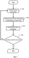
- FIG. 1 is a flowchart of a method for controlling an escalator system or a moving walkway system in accordance with some embodiments of the present application.
- the operating modes of the three-phase motor in the escalator system or the moving walkway system may include a variable frequency mode (VF mode), a first operating frequency mode (NET-Y mode), and a second operating frequency mode (NET- ⁇ mode).
- VF mode variable frequency mode
- NET-Y mode first operating frequency mode
- NET- ⁇ mode second operating frequency mode
- the method described below may be implemented by various devices which include, for example, but are not limited to, control devices within the escalator system, control devices within the moving walkway system, and control devices independent of the systems, which are hereafter referred to collectively as control devices.
- the method shown in FIG. 1 begins at step 101.
- the control device determines a load value LOAD of the escalator system or the moving walkway system.
- the load value described herein is used to measure the actual work load of the escalator system or the moving walkway system, which includes, for example, but is not limited to, the number of occupants of the escalator system or the moving walkway system, and the weight carried by the escalator system or the moving walkway system, etc. Details of the load value are described below.
- step 102 the control device selects a suitable current operating mode for the three-phase motor in the escalator system or the moving walkway system based on the load value LOAD, so that the motor operates in the range with higher motor efficiency as much as possible.
- the current operating mode may be determined based on the following rules:
- a larger percentage value (e.g., 35%-45%) of the maximum allowable load (e.g., maximum number of persons carried or maximum load-bearing weight) of the escalator system or the moving walkway system may be set as the second threshold TH2; furthermore, the first threshold TH1 may be set as a smaller percentage value (e.g., 5%-6%) of the maximum allowable load, in addition to taking a value of 0.
- the maximum allowable load e.g., maximum number of persons carried or maximum load-bearing weight
- step 103 the control device generates a control command to operate the three-phase motor in the determined current operating mode.
- step 104 the control device will determine whether it is necessary to exit the control process for the escalator system or the moving walkway system, and if so, exit the process shown in FIG. 1 , otherwise, return to step 101.
- Trigger conditions for exiting the control process include, for example, but are not limited to, a user's immediate input of shutdown command or the user's preset timed shutdown command, etc.
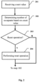
- the load value of the escalator system or the moving walkway system may be determined in the manner shown in FIG. 2 .
- the control device receives a count value from a photoelectric counting device (which comprises, for example, an inductive counter containing paired transmitters and receivers) arranged near an entrance and exit of the escalator system or the moving walkway system.
- a photoelectric counting device which comprises, for example, an inductive counter containing paired transmitters and receivers
- the control device determines the number of occupants of the escalator system or the moving walkway system based on the received count value.
- the count values of the photoelectric counting devices A and B will change when a person or object passes through the entrance and exit, and the difference of the count values at the current moment is obtained by subtracting the count values of the two counting devices at the current moment. And by adding this difference to the difference in the count values of multiple previous moments, the number of occupants at the current moment may be obtained.
- the count values of the photoelectric counting devices A and B may be reset regularly or irregularly.
- the method shown in FIG. 2 proceeds to step 203 after performing step 202.
- the control device determines whether it is necessary to perform a reset operation on the count values of the photoelectric counting devices A and B. If so, it proceeds to step 204 to perform the reset operation, otherwise, it proceeds to step 102. After performing step 204, the process shown in FIG. 2 also proceeds to step 102.
- the reset operation described above is triggered if the count value of the photoelectric counting device A at the entrance does not change within a sufficiently long period of time (optionally, the period of time is equal to the length of time it takes for a step of the escalator system or the moving walkway system to reach the exit from the entrance).
- the above reset operation is triggered when the cumulative value of the difference between the count values of the photoelectric counting devices A and B exceeds a set value THN (e.g., a value significantly greater than the maximum number of persons carried by the escalator system or the moving walkway system).
- a set value THN e.g., a value significantly greater than the maximum number of persons carried by the escalator system or the moving walkway system.
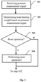
- the load value of the escalator system or the moving walkway system may be determined in the manner shown in FIG. 3 .
- the control device receives a pressure measurement signal from a pressure sensor arranged near an entrance and exit of the escalator system or the moving walkway system. Subsequently proceeding to step 302, the control device determines the load-bearing weight of the escalator system or the moving walkway system based on the received pressure measurement signal.
- the pressure signal is typically in the form of a pulse signal.
- the amplitude of the pressure signal measured by the pressure sensor at the entrance may be integrated over time, and the resulting integrated value may represent the load-bearing weight newly added to the escalator system or the moving walkway system; on the other hand, the amplitude of the pressure signal measured by the pressure sensor at the exit may be integrated over time, and the resulting integrated value may represent the load-bearing weight removed from the escalator system or the moving walkway system.
- pressure measurement signals are generated at pressure sensors C and D.
- a net increment (which may be positive, zero, or negative) in the load-bearing weight of the escalator system or the moving walkway system during the current sampling period may be obtained, and this net increment is added to the cumulative value of the net increment at previous multiple moments to obtain the load-bearing weight of the escalator system or the moving walkway system during the current sampling period.
- the cumulative value of the net increment may be reset regularly or irregularly.
- the method shown in FIG. 3 proceeds to step 303 after performing step 302.
- the control device determines whether it is necessary to perform a reset operation on the cumulative value of the net increment. If so, it proceeds to step 304 to perform the reset operation, otherwise, it proceeds to step 102. After performing step 304, the process shown in FIG. 3 also proceeds to step 102.
- the reset operation described above is triggered if the difference or net increment in the integrated value of the pressure measurement signals of pressure sensors C and D does not change within a sufficiently long period of time (optionally, the period of time is equal to the length of time it takes for a step of the escalator system or the moving walkway system to reach the exit from the entrance).
- the above reset operation is triggered when the cumulative value of the net increment exceeds a set value TW (e.g. significantly exceeds a value of the maximum load-bearing weight of the escalator system or the moving walkway system).
- TW e.g. significantly exceeds a value of the maximum load-bearing weight of the escalator system or the moving walkway system.
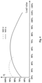
- the second threshold TH2 may be set equal to a critical value around which motor efficiency of the three-phase motor in the first operating frequency mode is close to its motor efficiency in the second operating frequency mode.
- FIG. 4 shows a relationship curve of motor efficiency versus load for the three-phase motor in the first operating frequency mode and the second operating frequency mode.
- the vertical axis represents the motor efficiency ⁇
- the horizontal axis represents the load value of the escalator system or the moving walkway system, which is expressed as a percentage relative to the rated load. As seen in FIG.
- the motor efficiency of the three-phase motor in NET-Y mode (dashed line) is better than that of the three-phase motor in NET- ⁇ mode (solid line) in the lower load range (20%-50% range in FIG. 4 ), but as the load value approaches 50%, the motor efficiency in NET-Y mode continuously decreases while the motor efficiency in NET- ⁇ mode continues to increase and tends to be consistent around 50%.
- a value within a small interval near 50% (such as 50% ⁇ 2%) may be used as the above critical value.
- FIG. 5 is a schematic block diagram of a control device.
- the control device shown in FIG. 5 may be used to implement the methods shown in FIGS. 1-3 for controlling the escalator system or the moving walkway system.
- a control device 500 includes a communication unit 510, a memory 520 (for example, non-volatile memory such as flash memory, ROM, hard disk drive, magnetic disk, optical disc), a controller 530, and a computer program 540.
- the communication unit 510 is configured to establish a communication connection between the control device and external devices (e.g., photoelectric counting device and pressure sensor, etc.) or a network (e.g., the Internet).
- external devices e.g., photoelectric counting device and pressure sensor, etc.
- a network e.g., the Internet
- the memory 520 stores the computer program 540 executable by the controller 530.
- the memory 520 may also store data generated when the controller 530 executes the computer program and data received from the external device via the communication unit 510 (e.g. count values, pressure signals, etc.).
- the controller 530 is configured to run the computer program 540 stored on the memory 520 and to access data on the memory 520 (e.g., to recall data received from the external device and to store in the memory 520 the results of calculations such as the difference of count values and the integral value of pressure signals, etc.).
- the computer program 540 may include computer instructions for implementing the methods described with the aid of FIGS. 1-3 , enabling the corresponding methods to be implemented when the computer program 540 is run on the controller 530.
- FIG. 6 is a schematic block diagram of a typical escalator system or a moving walkway system.
- a system 600 shown in FIG. 6 includes a conveying mechanism 610 (e.g., an escalator), a three-phase motor 620 for driving the conveying mechanism 610, a control device 630, and a measurement unit 640 (e.g., a photoelectric counting device or a pressure sensor, etc., arranged at the entrance and exit of the conveying mechanism).
- a conveying mechanism 610 e.g., an escalator
- a three-phase motor 620 for driving the conveying mechanism 610
- a control device 630 e.g., a control device 630
- a measurement unit 640 e.g., a photoelectric counting device or a pressure sensor, etc., arranged at the entrance and exit of the conveying mechanism.
- the three-phase motor 620 may operate in one of the variable frequency mode VF mode (variable frequency mode), NET-Y mode (first operating frequency mode) and NET- ⁇ mode (second operating frequency mode).
- the control device 630 may have various features of the device shown in FIG. 5 , which may be configured to implement the methods shown in FIGS. 1-3 for controlling the escalator system or the moving walkway system.
- the operating mode switching logic described above can be implemented simply by upgrading the control software running therein, which is advantageous in terms of reducing costs and shortening system development time.
- a computer-readable storage medium on which a computer program is stored which, when executed by a processor, can implement one or more steps contained in the method described above with the aid of FIGS. 1-3 .
- the computer-readable storage medium referred to in the application includes various types of computer storage media, and may be any available medium that may be accessed by a general-purpose or special-purpose computer.
- the computer-readable storage medium may include RAM, ROM, EPROM, E2PROM, registers, hard disks, removable disks, CD-ROM or other optical disk storage, magnetic disk storage or other magnetic storage devices, or any other transitory or non-transitory medium that may be used to carry or store a desired program code unit in the form of instructions or data structures and that may be accessed by a general-purpose or special-purpose computer or a general-purpose or special-purpose processor.
- the above combination should also be included in the protection scope of the computer-readable storage medium.
- An exemplary storage medium is coupled to the processor such that the processor can read and write information from and to the storage medium.
- the storage medium may be integrated into the processor.
- the processor and the storage medium may reside in the ASIC.
- the ASIC may reside in the user terminal.
- the processor and the storage medium may reside as discrete components in the user terminal.
Landscapes
- Engineering & Computer Science (AREA)
- Power Engineering (AREA)
- Escalators And Moving Walkways (AREA)
Applications Claiming Priority (1)
| Application Number | Priority Date | Filing Date | Title |
|---|---|---|---|
| CN202310092341.5A CN118405571A (zh) | 2023-01-30 | 2023-01-30 | 用于控制自动扶梯系统或自动人行道系统的装置和方法 |
Publications (1)
| Publication Number | Publication Date |
|---|---|
| EP4406902A1 true EP4406902A1 (de) | 2024-07-31 |
Family
ID=89535680
Family Applications (1)
| Application Number | Title | Priority Date | Filing Date |
|---|---|---|---|
| EP24150678.1A Pending EP4406902A1 (de) | 2023-01-30 | 2024-01-08 | Vorrichtung und verfahren zur steuerung eines fahrtreppensystems oder eines fahrsteigsystems |
Country Status (3)
| Country | Link |
|---|---|
| US (1) | US20240253951A1 (de) |
| EP (1) | EP4406902A1 (de) |
| CN (1) | CN118405571A (de) |
Citations (4)
| Publication number | Priority date | Publication date | Assignee | Title |
|---|---|---|---|---|
| US20030000801A1 (en) * | 2001-06-15 | 2003-01-02 | Otis Elevator Company | Process for switching between mains supply and a frequency inverter and vice versa |
| JP2007210710A (ja) * | 2006-02-07 | 2007-08-23 | Mitsubishi Electric Corp | 乗客コンベア |
| JP5496285B2 (ja) * | 2012-08-17 | 2014-05-21 | 東芝エレベータ株式会社 | 乗客コンベアの制御装置 |
| EP2743228A1 (de) * | 2012-12-17 | 2014-06-18 | Kone Corporation | Wechselrichter und Rolltreppensteuerungsvorrichtung mit dem Wechselrichter |
Family Cites Families (6)
| Publication number | Priority date | Publication date | Assignee | Title |
|---|---|---|---|---|
| US4738346A (en) * | 1985-10-29 | 1988-04-19 | Mitsubishi Denki Kabushiki Kaisha | Driving unit for passenger conveyor system |
| JP5119025B2 (ja) * | 2008-03-31 | 2013-01-16 | 株式会社日立産機システム | モータ制御装置、空気圧縮機、空気調和機、乗客コンベアの制御装置及びコンベアの制御装置 |
| CN103863932B (zh) * | 2012-12-17 | 2017-09-05 | 通力股份公司 | 变频器和具有变频器的扶梯控制装置 |
| WO2015094232A1 (en) * | 2013-12-18 | 2015-06-25 | Otis Elevator Company | Control strategies for multilevel line regenerative drive |
| US10926978B2 (en) * | 2017-06-08 | 2021-02-23 | Mitsubishi Electric Corporation | Man conveyor apparatus and controller for man conveyor apparatus |
| TWI913350B (zh) * | 2020-11-16 | 2026-02-01 | 瑞士商伊文修股份有限公司 | 用於乘客運輸系統的控制裝置 |
-
2023
- 2023-01-30 CN CN202310092341.5A patent/CN118405571A/zh active Pending
- 2023-11-15 US US18/510,097 patent/US20240253951A1/en active Pending
-
2024
- 2024-01-08 EP EP24150678.1A patent/EP4406902A1/de active Pending
Patent Citations (4)
| Publication number | Priority date | Publication date | Assignee | Title |
|---|---|---|---|---|
| US20030000801A1 (en) * | 2001-06-15 | 2003-01-02 | Otis Elevator Company | Process for switching between mains supply and a frequency inverter and vice versa |
| JP2007210710A (ja) * | 2006-02-07 | 2007-08-23 | Mitsubishi Electric Corp | 乗客コンベア |
| JP5496285B2 (ja) * | 2012-08-17 | 2014-05-21 | 東芝エレベータ株式会社 | 乗客コンベアの制御装置 |
| EP2743228A1 (de) * | 2012-12-17 | 2014-06-18 | Kone Corporation | Wechselrichter und Rolltreppensteuerungsvorrichtung mit dem Wechselrichter |
Also Published As
| Publication number | Publication date |
|---|---|
| CN118405571A (zh) | 2024-07-30 |
| US20240253951A1 (en) | 2024-08-01 |
Similar Documents
| Publication | Publication Date | Title |
|---|---|---|
| US7931128B2 (en) | Elevator device | |
| CN103030042B (zh) | 电梯设备 | |
| Hasan et al. | Performance evaluation of energy efficient intelligent elevator controllers | |
| US8348020B2 (en) | Elevator control device with carrier frequency switch circuit | |
| US8794388B2 (en) | Elevator group control apparatus | |
| CN102910505B (zh) | 具有多种工作模式的电梯节能装置及其控制方法 | |
| CN107187966A (zh) | 一种基于人数检测结果的多部电梯控制方法及系统 | |
| US7882937B2 (en) | Elevating machine control apparatus | |
| CN102701077A (zh) | 起重机吊钩位置的控制系统、控制方法及起重机 | |
| CN115724350A (zh) | 起重系统及其控制方法、装置、电子设备和存储介质 | |
| CN104854009A (zh) | 升降机速度控制 | |
| US20240253951A1 (en) | Apparatus and method for controlling an escalator system or an automated walkway system | |
| JP5489873B2 (ja) | 電気チェーンブロック及びその制御方法 | |
| CN104310190A (zh) | 扶梯控制系统及扶梯运行控制方法 | |
| CN103896145B (zh) | 扶梯自动调速方法 | |
| KR101261763B1 (ko) | 엘리베이터의 제어장치 | |
| CN103253565B (zh) | 电梯及其运行速度设置的方法和装置 | |
| CN102633170B (zh) | 电梯节能装置及其控制方法 | |
| JP5901166B2 (ja) | 荷役時間を短縮する港湾荷役機器の制御方法と港湾荷役機器 | |
| JP2010143692A (ja) | エレベータ装置 | |
| US10926978B2 (en) | Man conveyor apparatus and controller for man conveyor apparatus | |
| CN207536952U (zh) | 一种电梯运行速度检测装置及电梯 | |
| JP2014172668A (ja) | エレベータシステム | |
| JP6294802B2 (ja) | エレベータ装置およびエレベータ装置の振動検出方法 | |
| CN103708307B (zh) | 一种电梯控制方法及电梯控制系统 |
Legal Events
| Date | Code | Title | Description |
|---|---|---|---|
| PUAI | Public reference made under article 153(3) epc to a published international application that has entered the european phase |
Free format text: ORIGINAL CODE: 0009012 |
|
| STAA | Information on the status of an ep patent application or granted ep patent |
Free format text: STATUS: THE APPLICATION HAS BEEN PUBLISHED |
|
| AK | Designated contracting states |
Kind code of ref document: A1 Designated state(s): AL AT BE BG CH CY CZ DE DK EE ES FI FR GB GR HR HU IE IS IT LI LT LU LV MC ME MK MT NL NO PL PT RO RS SE SI SK SM TR |
|
| STAA | Information on the status of an ep patent application or granted ep patent |
Free format text: STATUS: REQUEST FOR EXAMINATION WAS MADE |
|
| 17P | Request for examination filed |
Effective date: 20250113 |
|
| STAA | Information on the status of an ep patent application or granted ep patent |
Free format text: STATUS: EXAMINATION IS IN PROGRESS |
|
| 17Q | First examination report despatched |
Effective date: 20250605 |