EP4403778A2 - Zentrifugalgebläsesystem und brennstoffzelle damit - Google Patents
Zentrifugalgebläsesystem und brennstoffzelle damit Download PDFInfo
- Publication number
- EP4403778A2 EP4403778A2 EP24181641.2A EP24181641A EP4403778A2 EP 4403778 A2 EP4403778 A2 EP 4403778A2 EP 24181641 A EP24181641 A EP 24181641A EP 4403778 A2 EP4403778 A2 EP 4403778A2
- Authority
- EP
- European Patent Office
- Prior art keywords
- blower
- series
- blower unit
- outlet
- gas
- Prior art date
- Legal status (The legal status is an assumption and is not a legal conclusion. Google has not performed a legal analysis and makes no representation as to the accuracy of the status listed.)
- Pending
Links
Images


Classifications
-
- F—MECHANICAL ENGINEERING; LIGHTING; HEATING; WEAPONS; BLASTING
- F04—POSITIVE - DISPLACEMENT MACHINES FOR LIQUIDS; PUMPS FOR LIQUIDS OR ELASTIC FLUIDS
- F04D—NON-POSITIVE-DISPLACEMENT PUMPS
- F04D17/00—Radial-flow pumps, e.g. centrifugal pumps; Helico-centrifugal pumps
- F04D17/08—Centrifugal pumps
- F04D17/10—Centrifugal pumps for compressing or evacuating
- F04D17/12—Multi-stage pumps
-
- F—MECHANICAL ENGINEERING; LIGHTING; HEATING; WEAPONS; BLASTING
- F04—POSITIVE - DISPLACEMENT MACHINES FOR LIQUIDS; PUMPS FOR LIQUIDS OR ELASTIC FLUIDS
- F04D—NON-POSITIVE-DISPLACEMENT PUMPS
- F04D25/00—Pumping installations or systems
- F04D25/16—Combinations of two or more pumps ; Producing two or more separate gas flows
- F04D25/166—Combinations of two or more pumps ; Producing two or more separate gas flows using fans
-
- B—PERFORMING OPERATIONS; TRANSPORTING
- B60—VEHICLES IN GENERAL
- B60L—PROPULSION OF ELECTRICALLY-PROPELLED VEHICLES; SUPPLYING ELECTRIC POWER FOR AUXILIARY EQUIPMENT OF ELECTRICALLY-PROPELLED VEHICLES; ELECTRODYNAMIC BRAKE SYSTEMS FOR VEHICLES IN GENERAL; MAGNETIC SUSPENSION OR LEVITATION FOR VEHICLES; MONITORING OPERATING VARIABLES OF ELECTRICALLY-PROPELLED VEHICLES; ELECTRIC SAFETY DEVICES FOR ELECTRICALLY-PROPELLED VEHICLES
- B60L50/00—Electric propulsion with power supplied within the vehicle
- B60L50/50—Electric propulsion with power supplied within the vehicle using propulsion power supplied by batteries or fuel cells
-
- F—MECHANICAL ENGINEERING; LIGHTING; HEATING; WEAPONS; BLASTING
- F04—POSITIVE - DISPLACEMENT MACHINES FOR LIQUIDS; PUMPS FOR LIQUIDS OR ELASTIC FLUIDS
- F04D—NON-POSITIVE-DISPLACEMENT PUMPS
- F04D17/00—Radial-flow pumps, e.g. centrifugal pumps; Helico-centrifugal pumps
- F04D17/08—Centrifugal pumps
- F04D17/16—Centrifugal pumps for displacing without appreciable compression
-
- F—MECHANICAL ENGINEERING; LIGHTING; HEATING; WEAPONS; BLASTING
- F04—POSITIVE - DISPLACEMENT MACHINES FOR LIQUIDS; PUMPS FOR LIQUIDS OR ELASTIC FLUIDS
- F04D—NON-POSITIVE-DISPLACEMENT PUMPS
- F04D29/00—Details, component parts, or accessories
- F04D29/26—Rotors specially for elastic fluids
- F04D29/28—Rotors specially for elastic fluids for centrifugal or helico-centrifugal pumps for radial-flow or helico-centrifugal pumps
- F04D29/281—Rotors specially for elastic fluids for centrifugal or helico-centrifugal pumps for radial-flow or helico-centrifugal pumps for fans or blowers
-
- H—ELECTRICITY
- H01—ELECTRIC ELEMENTS
- H01M—PROCESSES OR MEANS, e.g. BATTERIES, FOR THE DIRECT CONVERSION OF CHEMICAL ENERGY INTO ELECTRICAL ENERGY
- H01M8/00—Fuel cells; Manufacture thereof
- H01M8/002—Shape, form of a fuel cell
- H01M8/004—Cylindrical, tubular or wound
-
- H—ELECTRICITY
- H01—ELECTRIC ELEMENTS
- H01M—PROCESSES OR MEANS, e.g. BATTERIES, FOR THE DIRECT CONVERSION OF CHEMICAL ENERGY INTO ELECTRICAL ENERGY
- H01M8/00—Fuel cells; Manufacture thereof
- H01M8/04—Auxiliary arrangements, e.g. for control of pressure or for circulation of fluids
-
- H—ELECTRICITY
- H01—ELECTRIC ELEMENTS
- H01M—PROCESSES OR MEANS, e.g. BATTERIES, FOR THE DIRECT CONVERSION OF CHEMICAL ENERGY INTO ELECTRICAL ENERGY
- H01M8/00—Fuel cells; Manufacture thereof
- H01M8/04—Auxiliary arrangements, e.g. for control of pressure or for circulation of fluids
- H01M8/04082—Arrangements for control of reactant parameters, e.g. pressure or concentration
- H01M8/04089—Arrangements for control of reactant parameters, e.g. pressure or concentration of gaseous reactants
-
- H—ELECTRICITY
- H01—ELECTRIC ELEMENTS
- H01M—PROCESSES OR MEANS, e.g. BATTERIES, FOR THE DIRECT CONVERSION OF CHEMICAL ENERGY INTO ELECTRICAL ENERGY
- H01M8/00—Fuel cells; Manufacture thereof
- H01M8/04—Auxiliary arrangements, e.g. for control of pressure or for circulation of fluids
- H01M8/04298—Processes for controlling fuel cells or fuel cell systems
- H01M8/04694—Processes for controlling fuel cells or fuel cell systems characterised by variables to be controlled
- H01M8/04746—Pressure; Flow
- H01M8/04776—Pressure; Flow at auxiliary devices, e.g. reformer, compressor, burner
-
- H—ELECTRICITY
- H01—ELECTRIC ELEMENTS
- H01M—PROCESSES OR MEANS, e.g. BATTERIES, FOR THE DIRECT CONVERSION OF CHEMICAL ENERGY INTO ELECTRICAL ENERGY
- H01M8/00—Fuel cells; Manufacture thereof
- H01M8/10—Fuel cells with solid electrolytes
- H01M8/12—Fuel cells with solid electrolytes operating at high temperature, e.g. with stabilised ZrO2 electrolyte
-
- H—ELECTRICITY
- H01—ELECTRIC ELEMENTS
- H01M—PROCESSES OR MEANS, e.g. BATTERIES, FOR THE DIRECT CONVERSION OF CHEMICAL ENERGY INTO ELECTRICAL ENERGY
- H01M8/00—Fuel cells; Manufacture thereof
- H01M8/24—Grouping of fuel cells, e.g. stacking of fuel cells
- H01M8/241—Grouping of fuel cells, e.g. stacking of fuel cells with solid or matrix-supported electrolytes
- H01M8/2425—High-temperature cells with solid electrolytes
- H01M8/243—Grouping of unit cells of tubular or cylindrical configuration
-
- H—ELECTRICITY
- H01—ELECTRIC ELEMENTS
- H01M—PROCESSES OR MEANS, e.g. BATTERIES, FOR THE DIRECT CONVERSION OF CHEMICAL ENERGY INTO ELECTRICAL ENERGY
- H01M8/00—Fuel cells; Manufacture thereof
- H01M8/10—Fuel cells with solid electrolytes
- H01M8/12—Fuel cells with solid electrolytes operating at high temperature, e.g. with stabilised ZrO2 electrolyte
- H01M2008/1293—Fuel cells with solid oxide electrolytes
-
- H—ELECTRICITY
- H01—ELECTRIC ELEMENTS
- H01M—PROCESSES OR MEANS, e.g. BATTERIES, FOR THE DIRECT CONVERSION OF CHEMICAL ENERGY INTO ELECTRICAL ENERGY
- H01M2300/00—Electrolytes
- H01M2300/0017—Non-aqueous electrolytes
- H01M2300/0065—Solid electrolytes
- H01M2300/0068—Solid electrolytes inorganic
- H01M2300/0071—Oxides
-
- Y—GENERAL TAGGING OF NEW TECHNOLOGICAL DEVELOPMENTS; GENERAL TAGGING OF CROSS-SECTIONAL TECHNOLOGIES SPANNING OVER SEVERAL SECTIONS OF THE IPC; TECHNICAL SUBJECTS COVERED BY FORMER USPC CROSS-REFERENCE ART COLLECTIONS [XRACs] AND DIGESTS
- Y02—TECHNOLOGIES OR APPLICATIONS FOR MITIGATION OR ADAPTATION AGAINST CLIMATE CHANGE
- Y02E—REDUCTION OF GREENHOUSE GAS [GHG] EMISSIONS, RELATED TO ENERGY GENERATION, TRANSMISSION OR DISTRIBUTION
- Y02E60/00—Enabling technologies; Technologies with a potential or indirect contribution to GHG emissions mitigation
- Y02E60/30—Hydrogen technology
- Y02E60/50—Fuel cells
-
- Y—GENERAL TAGGING OF NEW TECHNOLOGICAL DEVELOPMENTS; GENERAL TAGGING OF CROSS-SECTIONAL TECHNOLOGIES SPANNING OVER SEVERAL SECTIONS OF THE IPC; TECHNICAL SUBJECTS COVERED BY FORMER USPC CROSS-REFERENCE ART COLLECTIONS [XRACs] AND DIGESTS
- Y02—TECHNOLOGIES OR APPLICATIONS FOR MITIGATION OR ADAPTATION AGAINST CLIMATE CHANGE
- Y02T—CLIMATE CHANGE MITIGATION TECHNOLOGIES RELATED TO TRANSPORTATION
- Y02T10/00—Road transport of goods or passengers
- Y02T10/60—Other road transportation technologies with climate change mitigation effect
- Y02T10/70—Energy storage systems for electromobility, e.g. batteries
Definitions
- This invention relates to centrifugal blowers and to fuel cells incorporating same.
- Centrifugal blowers or centrifugal fans, are a well known type of device for providing a flow or movement of a gaseous medium.
- a common type of centrifugal blower includes a housing having an axially directed gas inlet and a radially directed gas outlet, an impeller disposed within the housing for drawing gas at a first pressure into the inlet and expelling gas at a second higher pressure through the outlet and a motor for driving, i.e., spinning, the impeller.
- Variations of this general type of centrifugal blower are disclosed in, e.g., U.S. Patent Nos.
- Centrifugal blowers in single unit and multiple independent unit configurations have been disclosed as components of cooling systems for computers, servers and other heat-generating electrical and electronic devices and equipment. See, e.g., U.S. Patent Nos. 6,525,935 ; 7,184,265 ; 7,744,341 ; 7,802,617 ; 7,864,525 ; 7,885,068 ; 7,948,750 ; 7,902,617 ; and, 7,885,068 , the entire contents of which are incorporated by reference herein.
- Centrifugal blowers of the general type referred to above have been disclosed as components of fuel cells, of both the polyelectrolyte membrane (PEM) and solid oxide fuel cell (SOFC) types, where they function in one or more capacities, e.g., providing a flow of an oxidizer-containing gas such as air to the cathode elements of the fuel cell assembly and/or a flow of gaseous or vaporized fuel to its anode elements, recycling unspent fuel to the anode elements of the fuel cell assembly, providing a stream of cool air for cooling the fuel cell assembly or providing a stream of hot gas for vaporizing a liquid fuel prior to the external or internal reforming of the fuel to provide hydrogen for the operation of the fuel cell assembly.
- PEM polyelectrolyte membrane
- SOFC solid oxide fuel cell
- Fuel cell-blower assemblies featuring one or more centrifugal blowers are described in, e.g., U.S. Patent Nos. 6,497,971 ; 6,830,842 ; 7,314,679 and 7,943,260 , the entire contents of which are incorporated by reference herein.
- a fuel cell comprising:
- the multiple centrifugal blower system herein offers several advantages over a single centrifugal blower, particularly when incorporated in a fuel cell for managing the flow of gaseous media therein.
- Single centrifugal blowers require suitable control of the full range of motor rpm in order to meet fluctuating gas flow demands.
- optimum performance of the blower may be achieved by employing an impeller of relatively small size driven at relatively high rpm, e.g., 20,000 rpm and above, or an impeller of relatively large size driven at relatively low rpm, e.g., below 20,000 and more commonly, below 10,000.
- the first arrangement i.e., the use of a relatively small impeller driven at relatively high rpm, requires a more powerful and specialized motor which of necessity will draw a correspondingly greater amount of power for its operation.
- the second arrangement i.e., use of a relatively large impeller driven at relatively low rpm, makes control and fine tuning of the blower output more difficult due to the greater inertia of a large impeller.
- a blower employing a relatively high inertia impeller In order to prevent overshoot of the target pressure and gas flow, a blower employing a relatively high inertia impeller must be overdamped when tuning the blower for its expected range of gas pressure and flow capability. The effect of this overdamping to compensate for the relatively high inertia of the impeller is to cause the blower to be slow in responding to changing, and often rapidly changing, gas flow requirements. This characteristically slow response of a single centrifugal blower possessing a relatively high inertia impeller requires a more complicated control system for quickly responding to fluctuations in gas flow demand.
- Utilizing the multiple blower system of this invention for meeting the gas flow requirements of a fuel cell enables the system to benefit from both low inertia impellers for control as well as low drive motor rpm and power draw to provide required gas flow and pressure.
- Controlling one or more blower units in the system to provide a major portion of the target gas pressure and gas flow, e.g., 60-90% of the target gas pressure and gas flow, enables the remainder of the target gas pressure and gas flow to be provided by one or more other blower units in the system.
- the centrifugal blower system herein provides improved response times and control over a broad range of gas pressure and gas flow requirements than that of a single centrifugal blower unit.
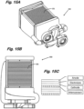
- dual centrifugal blower system 10 includes a first centrifugal blower unit 11 connected to a second centrifugal blower unit 12 through duct 13.
- First blower unit 11 includes a casing 14 having an axial inlet 15 and a radial outlet 16, an impeller 17 disposed within casing 14 for drawing a gaseous medium at a first pressure into axial inlet 15 and expelling gaseous medium at a second higher pressure through radial outlet 16 and an electric motor 18 for driving impeller 17.
- Second blower unit 12 includes a casing 19 and, as shown by the cutaway section of duct 13 in Fig. 1A , an impeller 20 disposed within casing 19 and driven by electrical motor 21 and an axial inlet 22 for receiving gas medium discharged from outlet 16 of first blower unit 11.
- Second blower unit further includes a radial outlet 23 and outlet gas stream housing 24.
- Figs. 1A and 1B indicate the general direction of the gas stream through the radial outlet of each blower unit in the series of blowers constituting the blower system.
- the trajectory of the gas stream expelled through outlet 16 of first blower unit 11 and the trajectory of the gas stream expelled through outlet 23 of second blower unit 12 are not parallel to their respective outlets but are at some angle thereto.
- interior, or guiding, surfaces of duct 13 and interior, or guiding, surfaces of gas stream housing 24 can be pitched at an angle ⁇ of from 12° to 20°, and preferably from 14° to 18°, relative to outlets 16 and 21.
- the embodiments of the dual blower systems of Figs. 2A, 2B , 3A, 3B, 4A and 4B are similar in structure to the dual blower system illustrated in Figs. 1A and 1B except for the orientation of the outlet of second blower unit 12 relative to the outlet of first blower unit 11.
- the angle of orientation is about 0°.
- this angle is about 90°
- the angle is about 180°
- in the blower system of Figs. 4A and 4B the angle is about 270°. All orientation angles are, of course, contemplated with the optimum angle of orientation for a given centrifugal blower system being made to depend upon the specific use to which the blower system is to be put.
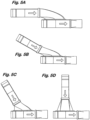
- Another angle of significance in the centrifugal blower system of the invention is the angle of pitch of the outlet of the first blower relative to the inlet of the second blower.
- the approximate angle is 0° in Fig. 5A , 30° in Fig. 5B , 60° in Fig. 5C and 90° in Fig. 5D .
- these blower pitch angles can assume values throughout the entire range of 0°-180°, again, with the optimum pitch value of a given blower system depending on specific application requirements.
- dual centrifugal blower systems have been disclosed with the output of the first blower being introduced into the inlet of the second blower and with each of the blowers having about the same range of gas pressure and gas flow output capability.
- the basic configuration of dual blower systems can be represented as "1 into 2" meaning that gas discharged from the first blower is introduced into the inlet of the second blower.
- numerous other arrangements are within the scope of this invention.
- centrifugal blower system herein include those with three, four and even a greater number of blower units, those in which the discharge from two or more blowers is introduced into the inlet of a single blower and those in which the discharge of a single blower is introduced into the inlets of two or more blowers.
- Blower systems of the foregoing kind can be designated, e.g., "1 into 2 into 3", etc., where the gas discharge stream of a preceding blower unit is ducted into the inlet of the following blower unit in the series, "1 and 2 into 3", etc., where the discharged streams of first and second blower units are commonly ducted into the inlet of a third blower unit and "1 into 2 and 3" where the discharge stream of a first blower unit is ducted into second and third blower units.
- valving may be provided to regulate the various gas flows in these systems.
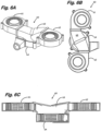
- centrifugal blower system 60 illustrated in Figs. 6A, 6B and 6C , the gas discharged from each of blower units 61 and 62 is introduced via duct 63 into the inlet of blower unit 64.
- Centrifugal blower system 60 is therefore an example of the " 1 and 2 into 3" configuration referred to above. This configuration enables control to be achieved whereby the gas flow capability of a single relatively large blower is obtained with the quick response characteristics of several smaller blowers.
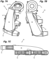
- Figs. 7, 7B and 7C show centrifugal blower system 70 with the output of single blower unit 70 being introduced into blower units 72 and 73 via common duct 74, an example of a "1 into 2 and 3" arrangement of blower units.
- This configuration of blower units enables use of a single primary gas pressure and gas flow supply blower with individual blowers downstream to provide more accurate control of two separate gas discharge streams.
- the discharge stream from first blower unit 81 of triple blower system 80 is introduced via duct 82 into second blower unit 83 with the discharge stream of blower unit 82 being introduced via duct 84 into third blower 85, such illustrating the " 1 into 2 into 3" configuration referred to above.
- This successive arrangement of three blowers permits blowers 83 and 85 to quickly and accurately respond to target gas pressure and gas flow requirements the greater part of which are provided by blower unit 81.
- Dual centrifugal gas blower system 90 possesses a first blower unit 91 of relatively large gas pressure and gas flow capability with the gas stream expelled therefrom being introduced via duct 92 into smaller blower unit 93.
- This arrangement of blowers of differing size enables fine adjustment of higher gas flow rates. Where gas flow requirements exceed that which can be achieved with a blower system in which the blower units are of approximately the same capability, the larger capacity blower unit can be supplemented by the lower capacity unit. This permits a greater range of gas flow while still realizing the quicker and more accurate flow control characteristics of the centrifugal blower system of this invention.
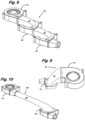
- the individual blower units, their interconnecting duct(s) aside, need not be in direct contact with each other but can be separated by a distance. Placing one or more blowers in the blower system of the invention at a separate location can be of advantage when optimal packaging considerations for a particular application favor such an arrangement.
- An embodiment of a blower of this type is shown in Fig. 10 where, in dual centrifugal blower system 100, first blower 101 is separated from second blower 102 by nearly the length of tubular duct 103.
- blower unit utilized in the centrifugal blower system of the invention can vary widely depending on gas pressure and gas flow requirements and end-use application.
- the following table lists some typical characteristics for a range of useful blower units: Size (mm) Rating Voltage (VDC) Power Current (AMP) Power Consumption (WATTS) Speed (RPM) Air Flow (CFM) Static Pressure (Inch-Water) Noise (dBA) Weight (g) 35x35x7 12 0.065 0.8 6300 0.9 0.27 22.2 8 45x45x20 12 0.04 0.48 3500 4.6 0.22 21 22.64 50x50x15 12 0.17 2.2 6000 4.7 0.97 42.2 30 50x50x15 12 0.1 1.2 5000 4.0 0.67 39.8 30 50x50x15 12 0.06 0.7 4000 3.0 0.40 33.4 30 50x50x15 12 0.044 0.5 3000 2.3 0.16 27 30 50x50x20 12 0.
- blower units possessing the forgoing characteristics can utilize any centrifugal blower unit having lesser or greater dimensions, voltage and power requirements, impeller rpm, gas pressure and gas flow capabilities, etc., than those listed in the table.
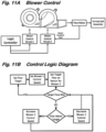
- Figs. 10A and 11B illustrate, respectively, a blower control system of a centrifugal blower system of the invention and a diagrammatic representation of its control logic. As those skilled in the art will recognize, these blower control operations can be carried out by a suitably programmed microprocessor.
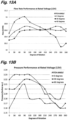
- Fig. 12 compares the typical flow rate performance of independently controlled first and second blowers in a dual centrifugal blower system such as that shown in Figs. 1A and 1B with a conventional larger single centrifugal blower of approximately equivalent gas flow capability. As the data plots show, the overdamping of the single blower which is required to avoid or suppress overshooting target gas flows resulted in a longer period of time to reach both low target flow and high target flow in contrast to the considerably faster times for achieving these target flow levels employing the multiple interconnected centrifugal blower system of the invention.
- Figs. 13A and 13B are graphical presentations of, respectively, gas flow rate and gas pressure performance characteristics for dual blower system configurations of the invention in which the pitch angles of the blower units are 0°, 30° and 60° (as shown in Figs. 5A, 5B and 5C ).
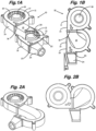
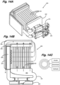
- Figs. 14A, 14B , 15A and 15B illustrate the use of the blower system of the invention to provide and mediate gas flows in an SOFC assembly of the tubular type ( Figs. 14A and 14B ) and planar type ( Figs. 15A and 15B ).
- first blower system 141 provides a gaseous fuel, e.g., hydrogen, to manifold 142 for distribution to the interior array 143 of tubular SOFC elements.
- a gaseous fuel e.g., hydrogen
- manifold 142 for distribution to the interior array 143 of tubular SOFC elements.
- Each tube in array 143 can be of known or conventional construction and, as shown in Fig. 14C , possesses an innermost fuel-contacting anode layer, intermediate electrolyte layer and outer cathode layer.
- Second blower system 144 distributes air, initially at ambient temperature, to manifold 145 from which it is released to provide a source of oxygen for the cathode component of each tubular SOFC element.
- the air entering manifold 145 grains heat from the hot combustion gases exiting tail burner 146 into heat exchanger 147.
- the dotted lines show the flow path of the heated air existing the outlets of manifold 145, passing through the SOFC array 143 and into tail burner 146 where it provides oxygen to support combustion of unspent fuel present in the exhaust gas emerging from the tubular SOFC elements into exhaust manifold 148 and from there into the tail burner.
- the hot combustion gases enter heat exchanger 147 where they serve to preheat incoming air provided by first blower system 141 as previously indicated.
- each planar SOFC element in array 151 includes anode, electrolyte, cathode and interconnect components.
Landscapes
- Engineering & Computer Science (AREA)
- Sustainable Energy (AREA)
- Life Sciences & Earth Sciences (AREA)
- Sustainable Development (AREA)
- Chemical Kinetics & Catalysis (AREA)
- Chemical & Material Sciences (AREA)
- Manufacturing & Machinery (AREA)
- Electrochemistry (AREA)
- General Chemical & Material Sciences (AREA)
- Mechanical Engineering (AREA)
- General Engineering & Computer Science (AREA)
- Power Engineering (AREA)
- Transportation (AREA)
- Fuel Cell (AREA)
- Structures Of Non-Positive Displacement Pumps (AREA)
Applications Claiming Priority (3)
| Application Number | Priority Date | Filing Date | Title |
|---|---|---|---|
| US13/168,280 US9017893B2 (en) | 2011-06-24 | 2011-06-24 | Fuel cell system with centrifugal blower system for providing a flow of gaseous medium thereto |
| PCT/US2012/042569 WO2012177494A1 (en) | 2011-06-24 | 2012-06-15 | Centrifugal blower system and fuel cell incorporating same |
| EP12730332.9A EP2724029B1 (de) | 2011-06-24 | 2012-06-15 | Zentrifugalgebläsesystem und brennstoffzelle damit |
Related Parent Applications (2)
| Application Number | Title | Priority Date | Filing Date |
|---|---|---|---|
| EP12730332.9A Division-Into EP2724029B1 (de) | 2011-06-24 | 2012-06-15 | Zentrifugalgebläsesystem und brennstoffzelle damit |
| EP12730332.9A Division EP2724029B1 (de) | 2011-06-24 | 2012-06-15 | Zentrifugalgebläsesystem und brennstoffzelle damit |
Publications (2)
| Publication Number | Publication Date |
|---|---|
| EP4403778A2 true EP4403778A2 (de) | 2024-07-24 |
| EP4403778A3 EP4403778A3 (de) | 2024-09-11 |
Family
ID=46395729
Family Applications (2)
| Application Number | Title | Priority Date | Filing Date |
|---|---|---|---|
| EP12730332.9A Active EP2724029B1 (de) | 2011-06-24 | 2012-06-15 | Zentrifugalgebläsesystem und brennstoffzelle damit |
| EP24181641.2A Pending EP4403778A3 (de) | 2011-06-24 | 2012-06-15 | Zentrifugalgebläsesystem und brennstoffzelle damit |
Family Applications Before (1)
| Application Number | Title | Priority Date | Filing Date |
|---|---|---|---|
| EP12730332.9A Active EP2724029B1 (de) | 2011-06-24 | 2012-06-15 | Zentrifugalgebläsesystem und brennstoffzelle damit |
Country Status (12)
| Country | Link |
|---|---|
| US (4) | US9017893B2 (de) |
| EP (2) | EP2724029B1 (de) |
| JP (2) | JP6109823B2 (de) |
| KR (1) | KR20140036314A (de) |
| CN (1) | CN103732924B (de) |
| AU (1) | AU2012273238B2 (de) |
| BR (1) | BR112013032691A2 (de) |
| CA (2) | CA2838961C (de) |
| MX (1) | MX344414B (de) |
| RU (1) | RU2567485C2 (de) |
| WO (1) | WO2012177494A1 (de) |
| ZA (1) | ZA201309343B (de) |
Families Citing this family (34)
| Publication number | Priority date | Publication date | Assignee | Title |
|---|---|---|---|---|
| US9017893B2 (en) * | 2011-06-24 | 2015-04-28 | Watt Fuel Cell Corp. | Fuel cell system with centrifugal blower system for providing a flow of gaseous medium thereto |
| US9074524B2 (en) * | 2011-12-09 | 2015-07-07 | Eaton Corporation | Air supply system with two-stage roots blower |
| US9464805B2 (en) * | 2013-01-16 | 2016-10-11 | Lochinvar, Llc | Modulating burner |
| WO2014126595A1 (en) | 2013-02-18 | 2014-08-21 | Parker-Hannifin Corporation | Modular fuel cell system |
| US9831510B2 (en) * | 2013-04-29 | 2017-11-28 | Audi Ag | Fuel cell system blower configuration |
| JP6253795B2 (ja) | 2013-11-06 | 2017-12-27 | ワット・フューエル・セル・コーポレイションWatt Fuel Cell Corp. | ガス状燃料cpox改質器及びcpox改質の方法 |
| EP3065854A2 (de) | 2013-11-06 | 2016-09-14 | Watt Fuel Cell Corp. | Reformer mit perowskit als struktureller komponente |
| EP3065855B1 (de) | 2013-11-06 | 2022-06-29 | Watt Fuel Cell Corp. | Flüssigbrennstoff-cpox-reformer und brennstoffzellensysteme sowie stromerzeugungsverfahren |
| JP6549601B2 (ja) | 2013-11-06 | 2019-07-24 | ワット・フューエル・セル・コーポレイションWatt Fuel Cell Corp. | ガス状燃料cpox改質器と燃料セルの統合システム、及び電気を生成する方法 |
| CN105705226B (zh) | 2013-11-06 | 2018-03-27 | 瓦特燃料电池公司 | 液体燃料催化部分氧化重整器和催化部分氧化重整方法 |
| EP3065861A2 (de) | 2013-11-06 | 2016-09-14 | Watt Fuel Cell Corp. | Chemischer reaktor mit verteiler zur verwaltung eines zustroms eines gasförmigen reaktionsmediums |
| CA2958748C (en) * | 2014-08-19 | 2023-04-04 | WATT Fuel Cell Corp | Multi-reformable fuel delivery systems and methods for fuel cells |
| WO2016044945A1 (en) * | 2014-09-25 | 2016-03-31 | Nuhn Industries Ltd. | Fluid pump with multiple pump heads |
| US10391464B2 (en) * | 2015-03-16 | 2019-08-27 | Watt Fuel Cell Corp. | Centrifugal blower system with internal gas mixing and gas phase chemical reactor incorporating same |
| JP2018087494A (ja) * | 2015-03-30 | 2018-06-07 | 株式会社デンソー | 送風装置 |
| US9969569B2 (en) * | 2015-09-22 | 2018-05-15 | Deere & Company | Agricultural vehicle pneumatic distribution system |
| CN105597208B (zh) * | 2016-01-26 | 2019-01-04 | 北京怡和嘉业医疗科技股份有限公司 | 一种呼吸机 |
| CN106917777B (zh) * | 2016-11-14 | 2019-09-06 | 奇鋐科技股份有限公司 | 风扇框体结构及具有该风扇框体的风扇 |
| CN106870425B (zh) * | 2016-11-14 | 2020-02-11 | 奇鋐科技股份有限公司 | 串联风扇倾斜结构 |
| US20180156234A1 (en) * | 2016-12-05 | 2018-06-07 | Asia Vital Components Co., Ltd. | Fan frame body structure and fan with the fan frame body |
| CN106482195A (zh) * | 2016-12-29 | 2017-03-08 | 宁波方太厨具有限公司 | 串联双风机降噪型吸油烟机 |
| DE102017107601B4 (de) * | 2017-04-10 | 2019-11-07 | Gardner Denver Deutschland Gmbh | Verfahren zur Steuerung eines Schraubenverdichters |
| JP7300184B2 (ja) * | 2017-09-13 | 2023-06-29 | ワット・フューエル・セル・コーポレイション | 遠心ブロワシステム用空気取り入れアセンブリ及びこれを内蔵する燃料電池 |
| US10847823B2 (en) * | 2017-10-04 | 2020-11-24 | Fuelcell Energy, Inc. | Fuel cell stack inlet flow control |
| DE102017220855A1 (de) * | 2017-11-22 | 2019-05-23 | Robert Bosch Gmbh | Turbokompressor, insbesondere für ein Brennstoffzellensystem |
| JP2019143903A (ja) * | 2018-02-22 | 2019-08-29 | パナソニックIpマネジメント株式会社 | 送風装置 |
| US11754092B2 (en) * | 2018-05-22 | 2023-09-12 | Micronel Ag | Radial turbomachine |
| US11236762B2 (en) * | 2019-04-26 | 2022-02-01 | Johnson Controls Technology Company | Variable geometry of a housing for a blower assembly |
| CN112377462B (zh) * | 2020-10-13 | 2021-12-10 | 宁波方太厨具有限公司 | 一种导流装置、应用有该导流装置的离心风机及吸油烟机 |
| KR20230034529A (ko) * | 2021-09-03 | 2023-03-10 | 현대자동차주식회사 | 플랫형 연료 전지 장치 |
| EP4505076A1 (de) | 2022-05-11 | 2025-02-12 | Watt Fuel Cell Corp. | Gebläse- und luftfilteranordnung |
| AU2023269821A1 (en) | 2022-05-11 | 2024-10-31 | Watt Fuel Cell Corp. | Blower filter assembly |
| CN115224422B (zh) * | 2022-07-21 | 2024-05-31 | 深圳供电局有限公司 | 隔离装置及电动汽车 |
| CN120225780A (zh) * | 2023-02-03 | 2025-06-27 | 瓦特燃料电池公司 | 倒置离心式鼓风机系统及包括该系统的燃料电池 |
Citations (20)
| Publication number | Priority date | Publication date | Assignee | Title |
|---|---|---|---|---|
| US4917572A (en) | 1988-05-23 | 1990-04-17 | Airflow Research And Manufacturing Corporation | Centrifugal blower with axial clearance |
| US5839879A (en) | 1995-12-05 | 1998-11-24 | Denso Corporation | Centrifugal blower |
| US6497971B1 (en) | 1999-03-08 | 2002-12-24 | Utc Fuel Cells, Llc | Method and apparatus for improved delivery of input reactants to a fuel cell assembly |
| US6525935B2 (en) | 2001-03-12 | 2003-02-25 | Appro International, Inc. | Low profile highly accessible computer enclosure with plenum for cooling high power processors |
| US6830842B2 (en) | 2001-10-24 | 2004-12-14 | General Motors Corporation | Hydrogen purged motor for anode re-circulation blower |
| US6877954B2 (en) | 2003-04-08 | 2005-04-12 | Shueei-Muh Lin | Eccentric heat dispensing fans |
| US20060051203A1 (en) | 2004-09-09 | 2006-03-09 | Sen-Yung Lee | High volume fan device for removing heat from heat sources |
| US7061758B2 (en) | 2003-11-20 | 2006-06-13 | Asia Vital Components Co., Ltd. | Heat-dissipating fan device |
| US7184265B2 (en) | 2003-05-29 | 2007-02-27 | Lg Electronics Inc. | Cooling system for a portable computer |
| US7314679B2 (en) | 2003-07-15 | 2008-01-01 | Honda Motor Co., Ltd. | Air supply apparatus for a fuel cell |
| US7351031B2 (en) | 2004-11-01 | 2008-04-01 | Sunonwealth Electric Machine Industry Co., Ltd. | Centrifugal blower |
| US7744341B2 (en) | 2006-12-22 | 2010-06-29 | Fu Zhun Precision Industry (Shen Zhen) Co., Ltd. | Thermal module with centrifugal blower and electronic assembly incorporating the same |
| US7802617B2 (en) | 2006-07-14 | 2010-09-28 | Fu Zhun Precision Industry (Shen Zhen) Co., Ltd. | Heat dissipation apparatus |
| US7864525B2 (en) | 2008-06-04 | 2011-01-04 | Furui Precise Component (Kunshan) Co. Ltd. | Portable electronic device incorporating centrifugal blower |
| US7885068B2 (en) | 2006-06-05 | 2011-02-08 | Zalman Tech Co., Ltd. | Coolor for notebook computer |
| US7887290B2 (en) | 2005-01-27 | 2011-02-15 | Delta Electronics Inc. | Blower |
| US7891942B2 (en) | 2007-03-27 | 2011-02-22 | Coretronic Corporation | Centrifugal blower |
| US7902617B2 (en) | 2005-12-07 | 2011-03-08 | Intel Corporation | Forming a thin film electric cooler and structures formed thereby |
| US7943260B2 (en) | 2007-07-31 | 2011-05-17 | Ford Motor Company | System and method for recirculating unused fuel in fuel cell application |
| US7948750B2 (en) | 2009-03-21 | 2011-05-24 | Foxconn Technology Co., Ltd. | Portable electronic device incorporating extendable thermal module |
Family Cites Families (29)
| Publication number | Priority date | Publication date | Assignee | Title |
|---|---|---|---|---|
| DE1802281U (de) | 1957-04-12 | 1959-12-17 | Bosch Gmbh Robert | Magnetische antriebsvorrichtung fuer foerderpumpen, insbesondere kraftfahrzeuge od. dgl. |
| DE1802811U (de) | 1959-07-13 | 1959-12-24 | Metallgesellschaft Ag | Vierfach-geblaesekombination. |
| FR1261548A (fr) | 1960-06-21 | 1961-05-19 | Neu Sa | Perfectionnement apportés aux ventilateurs et compresseurs centrifuges à deux étages |
| US3332611A (en) * | 1964-05-13 | 1967-07-25 | Wahl Clipper Corp | Motor-fan assembly for electric hair dryer |
| US3387769A (en) | 1966-10-03 | 1968-06-11 | Worthington Corp | Multistage turbomachine |
| US3830041A (en) * | 1971-10-20 | 1974-08-20 | Environeering | Foam breaker |
| DE3025598A1 (de) | 1980-07-05 | 1982-02-04 | Werner Dr. 8972 Sonthofen Röhrs | Druck- und mengenregulierbares verbundgeblaese |
| JPS6125996A (ja) * | 1984-07-13 | 1986-02-05 | Nippon Kikai Gijutsu Kk | 送風装置 |
| US4854822A (en) | 1988-08-24 | 1989-08-08 | Apollo Sprayers International, Inc. | Series impeller air pump for liquid sprayer |
| DE29504886U1 (de) | 1995-03-27 | 1995-07-27 | air-control international (Deutschland) GmbH, 91522 Ansbach | Entlüftungsgerät |
| JPH09209994A (ja) * | 1996-01-31 | 1997-08-12 | Daikin Ind Ltd | 遠心型多翼送風機およびこれを用いた換気装置 |
| FI101564B (fi) | 1997-01-17 | 1998-07-15 | Flaekt Woods Ab | Korkeapainepuhallin |
| GB9711498D0 (en) | 1997-06-05 | 1997-07-30 | Bright Ideas Limited | A fan system |
| JP2001052727A (ja) * | 1999-08-04 | 2001-02-23 | Mitsubishi Heavy Ind Ltd | 燃料電池発電システム |
| BE1012944A3 (nl) * | 1999-10-26 | 2001-06-05 | Atlas Copco Airpower Nv | Meertraps-compressoreenheid en werkwijze voor het regelen van een der gelijke meertraps-compressoreenheid. |
| RU2196254C2 (ru) * | 2001-02-14 | 2003-01-10 | Открытое акционерное общество "Борец" | Центробежный насос |
| DE60239114D1 (de) * | 2001-12-10 | 2011-03-17 | Resmed Ltd | Gebläsevorrichtung der CPAP/NIPPV-Art |
| US8517012B2 (en) * | 2001-12-10 | 2013-08-27 | Resmed Limited | Multiple stage blowers and volutes therefor |
| DE102004042720A1 (de) | 2004-03-02 | 2005-11-24 | Braun, Alfons | Mehrstufiges Sauggebläse mit mindestens zwei Radialgebläsen, insbesondere zum Einsatz in einem Saugbagger |
| CN100354530C (zh) * | 2004-12-21 | 2007-12-12 | 英业达股份有限公司 | 一种串行风扇组及其转速匹配曲线产生方法 |
| EP1926914A2 (de) * | 2005-09-19 | 2008-06-04 | Ingersoll-Rand Company | Mehrstufiges komprimierungssystem mit motoren mit verstellbarer drehzahl |
| JP4804186B2 (ja) * | 2006-03-28 | 2011-11-02 | キヤノン株式会社 | シート給送装置及び画像形成装置 |
| WO2007133771A2 (en) * | 2006-05-15 | 2007-11-22 | Island Sky Corporation | Multipurpose adiabatic potable water production apparatus and methods |
| TWI353682B (en) * | 2007-06-21 | 2011-12-01 | Young Green Energy Co | Fuel cell apparatus |
| RU2380575C2 (ru) * | 2008-03-12 | 2010-01-27 | Федеральное государственное унитарное предприятие "Государственный космический научно-производственный центр имени М.В.Хруничева" (ФГУП "ГКНПЦ им.М.В.Хруничева") | Шнекоцентробежный насос |
| DE102008030399B4 (de) * | 2008-06-26 | 2019-03-21 | Airbus Operations Gmbh | Luftkanal zur Umgebungsluftzufuhr in einem Flugzeug |
| DE102008051742B4 (de) * | 2008-10-15 | 2022-02-24 | Purem GmbH | Brennstoffzelle und Brennstoffzellensystem |
| US8376718B2 (en) * | 2009-06-24 | 2013-02-19 | Praxair Technology, Inc. | Multistage compressor installation |
| US9017893B2 (en) * | 2011-06-24 | 2015-04-28 | Watt Fuel Cell Corp. | Fuel cell system with centrifugal blower system for providing a flow of gaseous medium thereto |
-
2011
- 2011-06-24 US US13/168,280 patent/US9017893B2/en active Active
-
2012
- 2012-06-15 BR BR112013032691A patent/BR112013032691A2/pt not_active IP Right Cessation
- 2012-06-15 KR KR1020147001744A patent/KR20140036314A/ko not_active Ceased
- 2012-06-15 WO PCT/US2012/042569 patent/WO2012177494A1/en not_active Ceased
- 2012-06-15 RU RU2014102233/06A patent/RU2567485C2/ru active
- 2012-06-15 CA CA2838961A patent/CA2838961C/en active Active
- 2012-06-15 MX MX2013015118A patent/MX344414B/es active IP Right Grant
- 2012-06-15 EP EP12730332.9A patent/EP2724029B1/de active Active
- 2012-06-15 CN CN201280030634.0A patent/CN103732924B/zh active Active
- 2012-06-15 CA CA2923400A patent/CA2923400C/en active Active
- 2012-06-15 EP EP24181641.2A patent/EP4403778A3/de active Pending
- 2012-06-15 JP JP2014517037A patent/JP6109823B2/ja active Active
- 2012-06-15 AU AU2012273238A patent/AU2012273238B2/en active Active
-
2013
- 2013-12-11 ZA ZA2013/09343A patent/ZA201309343B/en unknown
-
2015
- 2015-03-24 US US14/667,033 patent/US9512846B2/en active Active
- 2015-03-24 US US14/666,993 patent/US10273961B2/en active Active
- 2015-03-24 US US14/667,015 patent/US9593686B2/en active Active
- 2015-10-07 JP JP2015199086A patent/JP6138210B2/ja active Active
Patent Citations (20)
| Publication number | Priority date | Publication date | Assignee | Title |
|---|---|---|---|---|
| US4917572A (en) | 1988-05-23 | 1990-04-17 | Airflow Research And Manufacturing Corporation | Centrifugal blower with axial clearance |
| US5839879A (en) | 1995-12-05 | 1998-11-24 | Denso Corporation | Centrifugal blower |
| US6497971B1 (en) | 1999-03-08 | 2002-12-24 | Utc Fuel Cells, Llc | Method and apparatus for improved delivery of input reactants to a fuel cell assembly |
| US6525935B2 (en) | 2001-03-12 | 2003-02-25 | Appro International, Inc. | Low profile highly accessible computer enclosure with plenum for cooling high power processors |
| US6830842B2 (en) | 2001-10-24 | 2004-12-14 | General Motors Corporation | Hydrogen purged motor for anode re-circulation blower |
| US6877954B2 (en) | 2003-04-08 | 2005-04-12 | Shueei-Muh Lin | Eccentric heat dispensing fans |
| US7184265B2 (en) | 2003-05-29 | 2007-02-27 | Lg Electronics Inc. | Cooling system for a portable computer |
| US7314679B2 (en) | 2003-07-15 | 2008-01-01 | Honda Motor Co., Ltd. | Air supply apparatus for a fuel cell |
| US7061758B2 (en) | 2003-11-20 | 2006-06-13 | Asia Vital Components Co., Ltd. | Heat-dissipating fan device |
| US20060051203A1 (en) | 2004-09-09 | 2006-03-09 | Sen-Yung Lee | High volume fan device for removing heat from heat sources |
| US7351031B2 (en) | 2004-11-01 | 2008-04-01 | Sunonwealth Electric Machine Industry Co., Ltd. | Centrifugal blower |
| US7887290B2 (en) | 2005-01-27 | 2011-02-15 | Delta Electronics Inc. | Blower |
| US7902617B2 (en) | 2005-12-07 | 2011-03-08 | Intel Corporation | Forming a thin film electric cooler and structures formed thereby |
| US7885068B2 (en) | 2006-06-05 | 2011-02-08 | Zalman Tech Co., Ltd. | Coolor for notebook computer |
| US7802617B2 (en) | 2006-07-14 | 2010-09-28 | Fu Zhun Precision Industry (Shen Zhen) Co., Ltd. | Heat dissipation apparatus |
| US7744341B2 (en) | 2006-12-22 | 2010-06-29 | Fu Zhun Precision Industry (Shen Zhen) Co., Ltd. | Thermal module with centrifugal blower and electronic assembly incorporating the same |
| US7891942B2 (en) | 2007-03-27 | 2011-02-22 | Coretronic Corporation | Centrifugal blower |
| US7943260B2 (en) | 2007-07-31 | 2011-05-17 | Ford Motor Company | System and method for recirculating unused fuel in fuel cell application |
| US7864525B2 (en) | 2008-06-04 | 2011-01-04 | Furui Precise Component (Kunshan) Co. Ltd. | Portable electronic device incorporating centrifugal blower |
| US7948750B2 (en) | 2009-03-21 | 2011-05-24 | Foxconn Technology Co., Ltd. | Portable electronic device incorporating extendable thermal module |
Also Published As
| Publication number | Publication date |
|---|---|
| US20150192134A1 (en) | 2015-07-09 |
| KR20140036314A (ko) | 2014-03-25 |
| EP2724029B1 (de) | 2025-08-06 |
| JP6109823B2 (ja) | 2017-04-05 |
| CN103732924B (zh) | 2017-03-29 |
| US20150192138A1 (en) | 2015-07-09 |
| RU2014102233A (ru) | 2015-07-27 |
| EP4403778A3 (de) | 2024-09-11 |
| US9593686B2 (en) | 2017-03-14 |
| CA2923400A1 (en) | 2012-12-27 |
| ZA201309343B (en) | 2017-08-30 |
| US10273961B2 (en) | 2019-04-30 |
| EP2724029A1 (de) | 2014-04-30 |
| CA2923400C (en) | 2018-12-04 |
| AU2012273238A1 (en) | 2014-01-16 |
| BR112013032691A2 (pt) | 2017-01-24 |
| JP2016042472A (ja) | 2016-03-31 |
| US20150194683A1 (en) | 2015-07-09 |
| JP6138210B2 (ja) | 2017-05-31 |
| AU2012273238B2 (en) | 2015-10-22 |
| JP2014523503A (ja) | 2014-09-11 |
| US9512846B2 (en) | 2016-12-06 |
| MX344414B (es) | 2016-12-15 |
| MX2013015118A (es) | 2014-02-27 |
| US9017893B2 (en) | 2015-04-28 |
| CA2838961A1 (en) | 2012-12-27 |
| CA2838961C (en) | 2016-05-24 |
| WO2012177494A1 (en) | 2012-12-27 |
| RU2567485C2 (ru) | 2015-11-10 |
| CN103732924A (zh) | 2014-04-16 |
| US20120328969A1 (en) | 2012-12-27 |
Similar Documents
| Publication | Publication Date | Title |
|---|---|---|
| EP4403778A2 (de) | Zentrifugalgebläsesystem und brennstoffzelle damit | |
| JP5361798B2 (ja) | 直列に接続されたセルスタックモジュールアッセンブリー | |
| US11976670B2 (en) | Centrifugal blower with integrated motor and blower volute which functions as a heat sink for the motor | |
| CA2437536C (en) | Fuel cell and method of operating the same | |
| US10923743B2 (en) | Gas supply, conditioning, and discharge systems and methods | |
| US6582843B1 (en) | Fuel cell system | |
| JP2019021545A (ja) | 燃料電池システム | |
| US20250329767A1 (en) | Curved (involute) fuel cell stack placement design | |
| TWI921519B (zh) | 具有整合式馬達及作為該馬達之散熱器之鼓風機蝸殼的離心鼓風機及包含其之燃料電池系統 | |
| US8771884B1 (en) | Reactant conditioning scheme for fuel cell systems | |
| KR20250141716A (ko) | 반전형 원심 블로워 시스템 및 이를 포함하는 연료 전지 | |
| JP2024516063A (ja) | 燃料電池における空気流を制御するシステムおよび方法 | |
| WO2018126045A1 (en) | External mixer-eductor-oxidizer and module connections thereof | |
| JPS6276264A (ja) | 積層形燃料電池 |
Legal Events
| Date | Code | Title | Description |
|---|---|---|---|
| PUAI | Public reference made under article 153(3) epc to a published international application that has entered the european phase |
Free format text: ORIGINAL CODE: 0009012 |
|
| STAA | Information on the status of an ep patent application or granted ep patent |
Free format text: STATUS: THE APPLICATION HAS BEEN PUBLISHED |
|
| AC | Divisional application: reference to earlier application |
Ref document number: 2724029 Country of ref document: EP Kind code of ref document: P |
|
| AK | Designated contracting states |
Kind code of ref document: A2 Designated state(s): AL AT BE BG CH CY CZ DE DK EE ES FI FR GB GR HR HU IE IS IT LI LT LU LV MC MK MT NL NO PL PT RO RS SE SI SK SM TR |
|
| REG | Reference to a national code |
Ref country code: DE Ref legal event code: R079 Free format text: PREVIOUS MAIN CLASS: F04D0025160000 Ipc: F04D0017160000 |
|
| PUAL | Search report despatched |
Free format text: ORIGINAL CODE: 0009013 |
|
| AK | Designated contracting states |
Kind code of ref document: A3 Designated state(s): AL AT BE BG CH CY CZ DE DK EE ES FI FR GB GR HR HU IE IS IT LI LT LU LV MC MK MT NL NO PL PT RO RS SE SI SK SM TR |
|
| RIC1 | Information provided on ipc code assigned before grant |
Ipc: H01M 8/12 20160101ALI20240806BHEP Ipc: H01M 8/243 20160101ALI20240806BHEP Ipc: H01M 8/04089 20160101ALI20240806BHEP Ipc: F04D 25/16 20060101ALI20240806BHEP Ipc: F04D 17/16 20060101AFI20240806BHEP |
|
| STAA | Information on the status of an ep patent application or granted ep patent |
Free format text: STATUS: REQUEST FOR EXAMINATION WAS MADE |
|
| 17P | Request for examination filed |
Effective date: 20250306 |
|
| STAA | Information on the status of an ep patent application or granted ep patent |
Free format text: STATUS: EXAMINATION IS IN PROGRESS |
|
| 17Q | First examination report despatched |
Effective date: 20260317 |