EP4403738A1 - Doppelschieber für rolladenpanzer und verbindungsprofil für einen schieber - Google Patents
Doppelschieber für rolladenpanzer und verbindungsprofil für einen schieber Download PDFInfo
- Publication number
- EP4403738A1 EP4403738A1 EP23207062.3A EP23207062A EP4403738A1 EP 4403738 A1 EP4403738 A1 EP 4403738A1 EP 23207062 A EP23207062 A EP 23207062A EP 4403738 A1 EP4403738 A1 EP 4403738A1
- Authority
- EP
- European Patent Office
- Prior art keywords
- wing
- fixing
- intermediate junction
- plane
- angle
- Prior art date
- Legal status (The legal status is an assumption and is not a legal conclusion. Google has not performed a legal analysis and makes no representation as to the accuracy of the status listed.)
- Granted
Links
Images

Classifications
-
- E—FIXED CONSTRUCTIONS
- E06—DOORS, WINDOWS, SHUTTERS, OR ROLLER BLINDS IN GENERAL; LADDERS
- E06B—FIXED OR MOVABLE CLOSURES FOR OPENINGS IN BUILDINGS, VEHICLES, FENCES OR LIKE ENCLOSURES IN GENERAL, e.g. DOORS, WINDOWS, BLINDS, GATES
- E06B9/00—Screening or protective devices for wall or similar openings, with or without operating or securing mechanisms; Closures of similar construction
- E06B9/56—Operating, guiding or securing devices or arrangements for roll-type closures; Spring drums; Tape drums; Counterweighting arrangements therefor
- E06B9/58—Guiding devices
-
- E—FIXED CONSTRUCTIONS
- E06—DOORS, WINDOWS, SHUTTERS, OR ROLLER BLINDS IN GENERAL; LADDERS
- E06B—FIXED OR MOVABLE CLOSURES FOR OPENINGS IN BUILDINGS, VEHICLES, FENCES OR LIKE ENCLOSURES IN GENERAL, e.g. DOORS, WINDOWS, BLINDS, GATES
- E06B9/00—Screening or protective devices for wall or similar openings, with or without operating or securing mechanisms; Closures of similar construction
- E06B9/02—Shutters, movable grilles, or other safety closing devices, e.g. against burglary
- E06B9/08—Roll-type closures
- E06B9/11—Roller shutters
-
- E—FIXED CONSTRUCTIONS
- E06—DOORS, WINDOWS, SHUTTERS, OR ROLLER BLINDS IN GENERAL; LADDERS
- E06B—FIXED OR MOVABLE CLOSURES FOR OPENINGS IN BUILDINGS, VEHICLES, FENCES OR LIKE ENCLOSURES IN GENERAL, e.g. DOORS, WINDOWS, BLINDS, GATES
- E06B9/00—Screening or protective devices for wall or similar openings, with or without operating or securing mechanisms; Closures of similar construction
- E06B9/56—Operating, guiding or securing devices or arrangements for roll-type closures; Spring drums; Tape drums; Counterweighting arrangements therefor
- E06B9/58—Guiding devices
- E06B2009/587—Mounting of guiding devices to supporting structure
Definitions
- the present invention relates to a double slide device for roller shutter aprons and a junction profile for slides.
- It relates to the field of rolling shutters and, more particularly, to double slides for joining two juxtaposed rolling shutter aprons.
- This deformation can further cause the slats to move apart from each other in the middle part of the apron, placing strong stress on the joints that connect them.
- a solution to limit this risk may consist of increasing the coefficient of inertia to deformation of these blades of a rolling shutter apron. But to achieve this result, it is necessarily necessary to increase the thickness of the slats resulting in a larger section of the apron once rolled up. The consequence is a more imposing roller shutter box, which can pose an aesthetic problem, or even the integration of such a box in a construction.
- the slides of these roller shutters located at the lateral ends of the opening receiving such a bay can always be attached to the panels bordering this opening.
- behind the scenes of these same roller shutters at their adjacent lateral sides extend in front of this bay window. If it is in one piece and not cut into several panels adjoining each other through an intermediate upright, these slides cannot be attached to such intermediate uprights and necessarily extend into the void between the shutter box. rolling or the lintel of the opening and the threshold of the opening.
- This double slide must, again, be fixed, using tabs, at its upper end to a lintel, as the case may be, to the lower face of at least one of the roller shutter boxes and, at its lower end, on the threshold of the opening closed by said bay windows.
- EP 2 216 479 describes an end piece for a roller shutter slide, in particular adaptable to a double slide.
- the present invention also aims to make such attachment of a double slide profile or two assembled single slides more aesthetic and almost invisible, under the underside of a roller shutter box, under a lintel or on a threshold .
- the invention relates to a double slide device for roller shutter aprons, comprising two U-shaped grooves extending back to back in the same first plane or in planes forming an angle between them, on either side. other of a plane of symmetry, said double slide device comprising at each of its ends female interlocking means for receiving male interlocking means of a fixing tab.
- this device comprises two U-shaped profiles in the form of a slide defining, respectively, one of the U-shaped grooves and extending in the first plane, depending on the case in the planes forming an angle between them, these two U-shaped profiles being attached back to back on an intermediate junction profile of tubular or rail-shaped section and defining at its ends said female interlocking means (23).
- the intermediate junction profile comprises on its front and/or rear edge a covering wing giving said intermediate profile a T shape.
- the fixing tab comes from a blade folded in two on itself along a fold line so as to define two parallel blade branches, these blade branches having their end parts opposite the line folded perpendicularly in opposite directions so as to define fixing wings.
- a first advantage resulting from the invention consists in that through a standard U-shaped slide it is easily possible to design a double slide.
- This figure 1 illustrates a bay window 2 of large widths integrating into an opening 3 adapted in a construction.
- two juxtaposed roller shutters 4, 5 each comprise a box 6, which can extend to the interior side of the building where, as illustrated in the figure 1 , on the exterior side, in the upper part 7 of the opening 3.
- slides 10, 11 At the lateral ends 8, 9 of these rolling shutters 4, 5 extend, under their box 6, slides 10, 11 for guiding the slats 12 of the aprons 13 , 14 of its rolling shutters 4, 5, These slides 10, 11 are attached to the lateral sides 15, 16 of the opening 3.
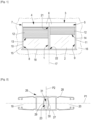
- the double slide device 1 At the height of the junction plane 17 of these rolling shutters 4, 5 and under the boxes 6 extends, from the latter and the threshold 18, the double slide device 1 according to an exemplary embodiment of the invention.
- the double slide device 1 has two U-shaped grooves 18; 19 defining slides for guiding apron slats, in the non-limiting example illustrated in the figure 1 , blades 12 of apron 13; 14.
- These two U-shaped grooves 18; 19 extend back to back, as the case may be, in the same first plane P1 (as visible in the figure 2 to 6 ), or in planes P1';P1" forming, between them, an angle ⁇ (as represented in the figure 8 ) on either side of a plane of symmetry P2.
- This double slide device of general shape of a longitudinal profile, comprises at each of its ends 21; 22, in other words from the ends of this profile, female interlocking means 23 for receiving male interlocking means 24 of a fixing tab 25.
- this double slide device 1 is defined by a profile 26 comprising a front wall 27 and a rear wall 28 extending in substantially parallel planes and between which are positioned bracing walls 29, 30 to delimit the two grooves in U 19; 20 and at least one intermediate tubular chamber 31 defining, at the ends 21; 22 of the profile 26, said female fitting means 23.
- this double slide device 1 comprises two U-shaped profiles 32; 33 extending in the first plane P1 and defining, respectively, a U-shaped groove 19; 20 and therefore a slide for guiding apron slats, in the non-limiting example illustrated in the figure 1 , blades 12 of apron 13; 14.
- These two U-shaped profiles 32, 33 are attached back to back on an intermediate junction profile 34, of tubular section or in the form of a rail as illustrated.
- This intermediate junction profile 34 extends in the plane of symmetry P2, here perpendicular to the first P1, and its ends 35 design said female interlocking means 23 at the ends 21, 22 of this double slide device 1.
- the intermediate junction profile 34 comprises on its front edge 37 and/or rear 38 a covering wing 39 giving said intermediate junction profile 34 a T-shaped section.
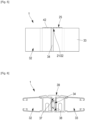
- the double slide device 1 comprises two U-shaped profiles 32; 33 extending in planes in planes P1';P1" distinct, forming an angle ⁇ , of the order of 90° in the example illustrated, knowing that this angle ⁇ between these planes P1' and P1 "can be between 0 and approximately 160°.
- These two U 32 profiles; 33 again define, respectively, a U-shaped groove 19; 20 and therefore a guide slide for apron slats.
- These two U-shaped profiles 32, 33 are attached back to back on an intermediate junction profile 34', of tubular section.
- This intermediate junction profile 34' in the form of a corner profile, extends in the plane of symmetry P2 and its ends 35 design said female interlocking means 23 at the ends 21, 22 of this double slide device 1.
- this intermediate junction profile 34' comprises on its interior longitudinal side at angle ⁇ 37' and/or exterior 38' a covering wing 39' substantially defined by two wing sections 39a and 39b giving said intermediate profile junction 34' a section in the form of an angle, these wing sections 39a and 39b forming between them an angle ⁇ identical to that between the planes P1' and P1".
- the double slide device 1 can be made from two simple, standard slides, designing U-shaped grooves 19, 20.
- the U-shaped profiles 32, 33 can be easily fixed, by screwing, riveting or gluing on the intermediate junction profile 34; 34'. Thanks to the covering wing 39; 39', the joint planes between the slides can be made perfectly invisible from the exterior and/or interior side of the construction.
- the U-shaped profiles 32, 33 designed by these standard slides are perfectly maintained.
- the T-shaped configuration depending on the case, in the form of an angle of the intermediate junction profile 34; 34' has the advantage of stiffening the double slide device 1.
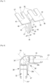
- a fixing bracket 25 comprises a first wing 40 extending in the plane of symmetry P2 and/or in a plane perpendicular to one of the planes P1', P1". It substantially defines said means of male socket 24 designed to be engaged in the female socket means 23.
- This first wing 40 is extended at one 41 of its ends by at least one fixing wing 42 extending in a plane perpendicular to the first wing 40 .
- the width 43 and the thickness 44 of the first wing 40 are designed to be able to engage in the end of the intermediate junction profile 34; 34' according to the second or third embodiment or in the intermediate tubular chamber 31 corresponding to the first embodiment.
- the width 45 of the fixing wing(s) 42 it is defined preferentially, but not imperatively, at most equal to the thickness 46 of a profile 26; 32, 33 of a double slide device 1.
- Such an advantageous design makes it possible to make invisible this or these fixing wings 42 at the ends 21; 22 of this device 1.
- the fixing bracket 25, in particular represented in the Figure 7 comes from a blade 45 folded in two on itself, along a fold line 46 so as to define two parallel blade branches 47, 48.
- These blade branches 47, 48 have their upper end parts 49 , 50, opposite the fold line 46, folded perpendicularly in opposite directions so as to define fixing wings 42.
- the lower end part 51, 52 of at least one of these blade branches 47, 48 designing the first wing 40 of the fixing bracket 25 it can be provided with anchoring means 53 in the profile junction intermediate 34; 34' according to the second or third embodiment or in the intermediate tubular chamber 31 corresponding to the first embodiment.
- Such anchoring means can take different embodiments. Thus, they can be in the form of a boss 54 or a step preventing the fixing tab 25 from coming off unexpectedly, particularly during assembly, from the double slide device 1.
- the fixing wing(s) 42 comprise at least one opening 55 for the passage of a fixing member such as a screw or a rivet.
- a fixing member such as a screw or a rivet.
- at least one opening 55 is defined in the form of a cutout in the front edge 56 and/or rear 57 of such a fixing wing 42, front edge 56 and rear 57.
- Such a design makes it possible to attach, depending on the case at the level of the underside of a box 6 of a rolling shutter 4, 5 or a lintel or even at the level of a threshold 18 one or more fixing members, such as as screws on which the cutouts of the fixing wing(s) 42 can be engaged by interlocking in a direction perpendicular to the plane P1, depending on the case P1' or P1", or even in the direction of the plane of symmetry P2.
Landscapes
- Engineering & Computer Science (AREA)
- Structural Engineering (AREA)
- Architecture (AREA)
- Civil Engineering (AREA)
- Operating, Guiding And Securing Of Roll- Type Closing Members (AREA)
- Curtains And Furnishings For Windows Or Doors (AREA)
Applications Claiming Priority (1)
| Application Number | Priority Date | Filing Date | Title |
|---|---|---|---|
| FR2300447A FR3145010B1 (fr) | 2023-01-18 | 2023-01-18 | Dispositif de coulisse double pour tabliers de volets roulants et profil de jonction pour coulisse |
Publications (2)
| Publication Number | Publication Date |
|---|---|
| EP4403738A1 true EP4403738A1 (de) | 2024-07-24 |
| EP4403738B1 EP4403738B1 (de) | 2026-01-14 |
Family
ID=85727069
Family Applications (1)
| Application Number | Title | Priority Date | Filing Date |
|---|---|---|---|
| EP23207062.3A Active EP4403738B1 (de) | 2023-01-18 | 2023-10-31 | Doppelschieber für rolladenpanzer und verbindungsprofil für einen schieber |
Country Status (2)
| Country | Link |
|---|---|
| EP (1) | EP4403738B1 (de) |
| FR (1) | FR3145010B1 (de) |
Citations (3)
| Publication number | Priority date | Publication date | Assignee | Title |
|---|---|---|---|---|
| EP2216479A2 (de) | 2009-02-09 | 2010-08-11 | profine GmbH | Endkappe für eine Rollladenlaufschiene |
| US20140262084A1 (en) * | 2013-03-15 | 2014-09-18 | Jacob Fleischman | Retractable wall system |
| EP3995664A1 (de) | 2020-11-09 | 2022-05-11 | Renson Sunprotection Screens NV | Zusammenbau einer schirmvorrichtung und eines befestigungsprofils zur befestigung eines schirmkasten dieser schirmvorrichtung |
-
2023
- 2023-01-18 FR FR2300447A patent/FR3145010B1/fr active Active
- 2023-10-31 EP EP23207062.3A patent/EP4403738B1/de active Active
Patent Citations (3)
| Publication number | Priority date | Publication date | Assignee | Title |
|---|---|---|---|---|
| EP2216479A2 (de) | 2009-02-09 | 2010-08-11 | profine GmbH | Endkappe für eine Rollladenlaufschiene |
| US20140262084A1 (en) * | 2013-03-15 | 2014-09-18 | Jacob Fleischman | Retractable wall system |
| EP3995664A1 (de) | 2020-11-09 | 2022-05-11 | Renson Sunprotection Screens NV | Zusammenbau einer schirmvorrichtung und eines befestigungsprofils zur befestigung eines schirmkasten dieser schirmvorrichtung |
Also Published As
| Publication number | Publication date |
|---|---|
| FR3145010A1 (fr) | 2024-07-19 |
| FR3145010B1 (fr) | 2025-03-14 |
| EP4403738B1 (de) | 2026-01-14 |
Similar Documents
| Publication | Publication Date | Title |
|---|---|---|
| FR2663671A1 (fr) | Systeme d'articulation de panneaux et application aux portes sectionnelles. | |
| EP3492675B1 (de) | Vorrichtung zum befestigen von lamellen an einem starren gitterpaneel, lamellenbefestigungskit an einem starren gitterpaneel und sichtschutzzaun, der mit diesem kit ausgestattet ist | |
| EP4403738B1 (de) | Doppelschieber für rolladenpanzer und verbindungsprofil für einen schieber | |
| EP2206869B1 (de) | Vorrichtung für die Motorisierung eines Fensters oder des Öffnungselements eines Schiebefensters | |
| EP3263826B1 (de) | Rollladen mit verstellbaren lamellen | |
| FR2981115A1 (fr) | Element de coffrage pour un volet roulant, destine a etre pose au niveau de la traverse haute d'un dormant rapporte au sein d'une baie de batiment | |
| EP1022427B1 (de) | Tür- oder Fenster- und Rolladenbaueinheit oder dergleichen | |
| EP1998000B1 (de) | Vorrichtung zur Befestigung einer Halteplatte einer ausklappbaren Struktur auf einer Befestigungslasche | |
| FR3077324A1 (fr) | Coffre pour une menuiserie destinee a equiper une baie de batiment, avec joues laterales | |
| EP2652232A1 (de) | Rotationsmechanismus für rollladenlatten | |
| FR2998608A1 (fr) | Volets roulants | |
| BE1019663A4 (fr) | Ensemble chambranle contre-chambranle. | |
| FR2956151A1 (fr) | Cale de reglage pour la fin de course d'enroulement d'un volet roulant, et installation de volet roulant comportant de telles cales de reglage | |
| FR2873400A1 (fr) | Ensemble de lames articulees, tablier de volet roulant et volet roulant ainsi forme | |
| EP3069637A1 (de) | Haltevorrichtung für stangen, die auf der vorderseite von jalousiekästen angepasst werden kann | |
| EP3660244A1 (de) | Verdunkelungsvorrichtung insbesondere für die herstellung von zäunen sowie montageverfahren einer solchen vorrichtung | |
| FR3099199A1 (fr) | Ouvrant pour une menuiserie destinée à équiper une baie de bâtiment | |
| EP1972750B1 (de) | Führungsschiene eines Rollladens | |
| FR2956692A1 (fr) | Dispositif d'occultation. | |
| FR3043120A1 (fr) | Cadre destine a porter le dormant d'un ouvrant | |
| FR2824102A1 (fr) | Volet a persiennes en profiles | |
| FR3132115A3 (fr) | Système de clôture, comprenant au moins un panneau treillis et au moins une lame occultante | |
| FR2755466A1 (fr) | Dispositif de montage d'un panneau coulissant | |
| EP1146197B1 (de) | Rollladenkasten | |
| EP1505247A1 (de) | Anbauteil für einen Rolladenkasten zur Aufnahme einer zusätzlichen Verdunkelungs- oder Schutzeinrichtung |
Legal Events
| Date | Code | Title | Description |
|---|---|---|---|
| PUAI | Public reference made under article 153(3) epc to a published international application that has entered the european phase |
Free format text: ORIGINAL CODE: 0009012 |
|
| STAA | Information on the status of an ep patent application or granted ep patent |
Free format text: STATUS: THE APPLICATION HAS BEEN PUBLISHED |
|
| AK | Designated contracting states |
Kind code of ref document: A1 Designated state(s): AL AT BE BG CH CY CZ DE DK EE ES FI FR GB GR HR HU IE IS IT LI LT LU LV MC ME MK MT NL NO PL PT RO RS SE SI SK SM TR |
|
| STAA | Information on the status of an ep patent application or granted ep patent |
Free format text: STATUS: REQUEST FOR EXAMINATION WAS MADE |
|
| 17P | Request for examination filed |
Effective date: 20241128 |
|
| RAP3 | Party data changed (applicant data changed or rights of an application transferred) |
Owner name: BHG |
|
| RBV | Designated contracting states (corrected) |
Designated state(s): AL AT BE BG CH CY CZ DE DK EE ES FI FR GB GR HR HU IE IS IT LI LT LU LV MC ME MK MT NL NO PL PT RO RS SE SI SK SM TR |
|
| RIC1 | Information provided on ipc code assigned before grant |
Ipc: E06B 9/58 20060101ALI20250602BHEP Ipc: E06B 9/11 20060101AFI20250602BHEP |
|
| GRAP | Despatch of communication of intention to grant a patent |
Free format text: ORIGINAL CODE: EPIDOSNIGR1 |
|
| STAA | Information on the status of an ep patent application or granted ep patent |
Free format text: STATUS: GRANT OF PATENT IS INTENDED |
|
| INTG | Intention to grant announced |
Effective date: 20251009 |
|
| GRAS | Grant fee paid |
Free format text: ORIGINAL CODE: EPIDOSNIGR3 |
|
| GRAA | (expected) grant |
Free format text: ORIGINAL CODE: 0009210 |
|
| STAA | Information on the status of an ep patent application or granted ep patent |
Free format text: STATUS: THE PATENT HAS BEEN GRANTED |
|
| AK | Designated contracting states |
Kind code of ref document: B1 Designated state(s): AL AT BE BG CH CY CZ DE DK EE ES FI FR GB GR HR HU IE IS IT LI LT LU LV MC ME MK MT NL NO PL PT RO RS SE SI SK SM TR |
|
| REG | Reference to a national code |
Ref country code: CH Ref legal event code: F10 Free format text: ST27 STATUS EVENT CODE: U-0-0-F10-F00 (AS PROVIDED BY THE NATIONAL OFFICE) Effective date: 20260114 Ref country code: GB Ref legal event code: FG4D Free format text: NOT ENGLISH |
|
| REG | Reference to a national code |
Ref country code: DE Ref legal event code: R096 Ref document number: 602023010696 Country of ref document: DE |
|
| REG | Reference to a national code |
Ref country code: IE Ref legal event code: FG4D Free format text: LANGUAGE OF EP DOCUMENT: FRENCH |