EP4403281A1 - Herstellungsverfahren für feine metallpartikel - Google Patents
Herstellungsverfahren für feine metallpartikel Download PDFInfo
- Publication number
- EP4403281A1 EP4403281A1 EP22886501.0A EP22886501A EP4403281A1 EP 4403281 A1 EP4403281 A1 EP 4403281A1 EP 22886501 A EP22886501 A EP 22886501A EP 4403281 A1 EP4403281 A1 EP 4403281A1
- Authority
- EP
- European Patent Office
- Prior art keywords
- metal particles
- iron
- catalyst
- carbon
- reaction
- Prior art date
- Legal status (The legal status is an assumption and is not a legal conclusion. Google has not performed a legal analysis and makes no representation as to the accuracy of the status listed.)
- Pending
Links
Images








Classifications
-
- B—PERFORMING OPERATIONS; TRANSPORTING
- B22—CASTING; POWDER METALLURGY
- B22F—WORKING METALLIC POWDER; MANUFACTURE OF ARTICLES FROM METALLIC POWDER; MAKING METALLIC POWDER; APPARATUS OR DEVICES SPECIALLY ADAPTED FOR METALLIC POWDER
- B22F1/00—Metallic powder; Treatment of metallic powder, e.g. to facilitate working or to improve properties
- B22F1/05—Metallic powder characterised by the size or surface area of the particles
-
- B—PERFORMING OPERATIONS; TRANSPORTING
- B01—PHYSICAL OR CHEMICAL PROCESSES OR APPARATUS IN GENERAL
- B01J—CHEMICAL OR PHYSICAL PROCESSES, e.g. CATALYSIS OR COLLOID CHEMISTRY; THEIR RELEVANT APPARATUS
- B01J23/00—Catalysts comprising metals or metal oxides or hydroxides, not provided for in group B01J21/00
- B01J23/70—Catalysts comprising metals or metal oxides or hydroxides, not provided for in group B01J21/00 of the iron group metals or copper
- B01J23/74—Iron group metals
- B01J23/745—Iron
-
- B—PERFORMING OPERATIONS; TRANSPORTING
- B22—CASTING; POWDER METALLURGY
- B22F—WORKING METALLIC POWDER; MANUFACTURE OF ARTICLES FROM METALLIC POWDER; MAKING METALLIC POWDER; APPARATUS OR DEVICES SPECIALLY ADAPTED FOR METALLIC POWDER
- B22F1/00—Metallic powder; Treatment of metallic powder, e.g. to facilitate working or to improve properties
- B22F1/05—Metallic powder characterised by the size or surface area of the particles
- B22F1/052—Metallic powder characterised by the size or surface area of the particles characterised by a mixture of particles of different sizes or by the particle size distribution
-
- B—PERFORMING OPERATIONS; TRANSPORTING
- B22—CASTING; POWDER METALLURGY
- B22F—WORKING METALLIC POWDER; MANUFACTURE OF ARTICLES FROM METALLIC POWDER; MAKING METALLIC POWDER; APPARATUS OR DEVICES SPECIALLY ADAPTED FOR METALLIC POWDER
- B22F1/00—Metallic powder; Treatment of metallic powder, e.g. to facilitate working or to improve properties
- B22F1/14—Treatment of metallic powder
- B22F1/142—Thermal or thermo-mechanical treatment
-
- B—PERFORMING OPERATIONS; TRANSPORTING
- B22—CASTING; POWDER METALLURGY
- B22F—WORKING METALLIC POWDER; MANUFACTURE OF ARTICLES FROM METALLIC POWDER; MAKING METALLIC POWDER; APPARATUS OR DEVICES SPECIALLY ADAPTED FOR METALLIC POWDER
- B22F1/00—Metallic powder; Treatment of metallic powder, e.g. to facilitate working or to improve properties
- B22F1/14—Treatment of metallic powder
- B22F1/145—Chemical treatment, e.g. passivation or decarburisation
-
- B—PERFORMING OPERATIONS; TRANSPORTING
- B22—CASTING; POWDER METALLURGY
- B22F—WORKING METALLIC POWDER; MANUFACTURE OF ARTICLES FROM METALLIC POWDER; MAKING METALLIC POWDER; APPARATUS OR DEVICES SPECIALLY ADAPTED FOR METALLIC POWDER
- B22F1/00—Metallic powder; Treatment of metallic powder, e.g. to facilitate working or to improve properties
- B22F1/16—Metallic particles coated with a non-metal
-
- B—PERFORMING OPERATIONS; TRANSPORTING
- B22—CASTING; POWDER METALLURGY
- B22F—WORKING METALLIC POWDER; MANUFACTURE OF ARTICLES FROM METALLIC POWDER; MAKING METALLIC POWDER; APPARATUS OR DEVICES SPECIALLY ADAPTED FOR METALLIC POWDER
- B22F9/00—Making metallic powder or suspensions thereof
- B22F9/02—Making metallic powder or suspensions thereof using physical processes
- B22F9/04—Making metallic powder or suspensions thereof using physical processes starting from solid material, e.g. by crushing, grinding or milling
-
- C—CHEMISTRY; METALLURGY
- C01—INORGANIC CHEMISTRY
- C01B—NON-METALLIC ELEMENTS; COMPOUNDS THEREOF; METALLOIDS OR COMPOUNDS THEREOF NOT COVERED BY SUBCLASS C01C
- C01B3/00—Hydrogen; Gaseous mixtures containing hydrogen; Separation of hydrogen from mixtures containing it; Purification of hydrogen; Reversible storage of hydrogen
- C01B3/02—Production of hydrogen; Production of gaseous mixtures containing hydrogen
- C01B3/22—Production of hydrogen; Production of gaseous mixtures containing hydrogen by decomposition of gaseous or liquid organic compounds
- C01B3/24—Production of hydrogen; Production of gaseous mixtures containing hydrogen by decomposition of gaseous or liquid organic compounds of hydrocarbons
- C01B3/26—Production of hydrogen; Production of gaseous mixtures containing hydrogen by decomposition of gaseous or liquid organic compounds of hydrocarbons using catalysts
-
- C—CHEMISTRY; METALLURGY
- C01—INORGANIC CHEMISTRY
- C01B—NON-METALLIC ELEMENTS; COMPOUNDS THEREOF; METALLOIDS OR COMPOUNDS THEREOF NOT COVERED BY SUBCLASS C01C
- C01B3/00—Hydrogen; Gaseous mixtures containing hydrogen; Separation of hydrogen from mixtures containing it; Purification of hydrogen; Reversible storage of hydrogen
- C01B3/02—Production of hydrogen; Production of gaseous mixtures containing hydrogen
- C01B3/22—Production of hydrogen; Production of gaseous mixtures containing hydrogen by decomposition of gaseous or liquid organic compounds
- C01B3/24—Production of hydrogen; Production of gaseous mixtures containing hydrogen by decomposition of gaseous or liquid organic compounds of hydrocarbons
- C01B3/28—Production of hydrogen; Production of gaseous mixtures containing hydrogen by decomposition of gaseous or liquid organic compounds of hydrocarbons using moving solid particles, e.g. fluidised bed technique
-
- B—PERFORMING OPERATIONS; TRANSPORTING
- B01—PHYSICAL OR CHEMICAL PROCESSES OR APPARATUS IN GENERAL
- B01J—CHEMICAL OR PHYSICAL PROCESSES, e.g. CATALYSIS OR COLLOID CHEMISTRY; THEIR RELEVANT APPARATUS
- B01J2235/00—Indexing scheme associated with group B01J35/00, related to the analysis techniques used to determine the catalysts form or properties
- B01J2235/15—X-ray diffraction
-
- B—PERFORMING OPERATIONS; TRANSPORTING
- B01—PHYSICAL OR CHEMICAL PROCESSES OR APPARATUS IN GENERAL
- B01J—CHEMICAL OR PHYSICAL PROCESSES, e.g. CATALYSIS OR COLLOID CHEMISTRY; THEIR RELEVANT APPARATUS
- B01J2235/00—Indexing scheme associated with group B01J35/00, related to the analysis techniques used to determine the catalysts form or properties
- B01J2235/30—Scanning electron microscopy; Transmission electron microscopy
-
- B—PERFORMING OPERATIONS; TRANSPORTING
- B22—CASTING; POWDER METALLURGY
- B22F—WORKING METALLIC POWDER; MANUFACTURE OF ARTICLES FROM METALLIC POWDER; MAKING METALLIC POWDER; APPARATUS OR DEVICES SPECIALLY ADAPTED FOR METALLIC POWDER
- B22F2301/00—Metallic composition of the powder or its coating
- B22F2301/15—Nickel or cobalt
-
- B—PERFORMING OPERATIONS; TRANSPORTING
- B22—CASTING; POWDER METALLURGY
- B22F—WORKING METALLIC POWDER; MANUFACTURE OF ARTICLES FROM METALLIC POWDER; MAKING METALLIC POWDER; APPARATUS OR DEVICES SPECIALLY ADAPTED FOR METALLIC POWDER
- B22F2301/00—Metallic composition of the powder or its coating
- B22F2301/35—Iron
-
- C—CHEMISTRY; METALLURGY
- C01—INORGANIC CHEMISTRY
- C01B—NON-METALLIC ELEMENTS; COMPOUNDS THEREOF; METALLOIDS OR COMPOUNDS THEREOF NOT COVERED BY SUBCLASS C01C
- C01B2203/00—Integrated processes for the production of hydrogen or synthesis gas
- C01B2203/02—Processes for making hydrogen or synthesis gas
- C01B2203/0266—Processes for making hydrogen or synthesis gas containing a decomposition step
- C01B2203/0277—Processes for making hydrogen or synthesis gas containing a decomposition step containing a catalytic decomposition step
-
- C—CHEMISTRY; METALLURGY
- C01—INORGANIC CHEMISTRY
- C01B—NON-METALLIC ELEMENTS; COMPOUNDS THEREOF; METALLOIDS OR COMPOUNDS THEREOF NOT COVERED BY SUBCLASS C01C
- C01B2203/00—Integrated processes for the production of hydrogen or synthesis gas
- C01B2203/04—Integrated processes for the production of hydrogen or synthesis gas containing a purification step for the hydrogen or the synthesis gas
-
- C—CHEMISTRY; METALLURGY
- C01—INORGANIC CHEMISTRY
- C01B—NON-METALLIC ELEMENTS; COMPOUNDS THEREOF; METALLOIDS OR COMPOUNDS THEREOF NOT COVERED BY SUBCLASS C01C
- C01B2203/00—Integrated processes for the production of hydrogen or synthesis gas
- C01B2203/04—Integrated processes for the production of hydrogen or synthesis gas containing a purification step for the hydrogen or the synthesis gas
- C01B2203/042—Purification by adsorption on solids
- C01B2203/043—Regenerative adsorption process in two or more beds, one for adsorption, the other for regeneration
-
- C—CHEMISTRY; METALLURGY
- C01—INORGANIC CHEMISTRY
- C01B—NON-METALLIC ELEMENTS; COMPOUNDS THEREOF; METALLOIDS OR COMPOUNDS THEREOF NOT COVERED BY SUBCLASS C01C
- C01B2203/00—Integrated processes for the production of hydrogen or synthesis gas
- C01B2203/10—Catalysts for performing the hydrogen forming reactions
- C01B2203/1041—Composition of the catalyst
- C01B2203/1047—Group VIII metal catalysts
-
- C—CHEMISTRY; METALLURGY
- C01—INORGANIC CHEMISTRY
- C01B—NON-METALLIC ELEMENTS; COMPOUNDS THEREOF; METALLOIDS OR COMPOUNDS THEREOF NOT COVERED BY SUBCLASS C01C
- C01B2203/00—Integrated processes for the production of hydrogen or synthesis gas
- C01B2203/10—Catalysts for performing the hydrogen forming reactions
- C01B2203/1041—Composition of the catalyst
- C01B2203/1047—Group VIII metal catalysts
- C01B2203/1052—Nickel or cobalt catalysts
-
- C—CHEMISTRY; METALLURGY
- C01—INORGANIC CHEMISTRY
- C01B—NON-METALLIC ELEMENTS; COMPOUNDS THEREOF; METALLOIDS OR COMPOUNDS THEREOF NOT COVERED BY SUBCLASS C01C
- C01B2203/00—Integrated processes for the production of hydrogen or synthesis gas
- C01B2203/12—Feeding the process for making hydrogen or synthesis gas
- C01B2203/1205—Composition of the feed
- C01B2203/1211—Organic compounds or organic mixtures used in the process for making hydrogen or synthesis gas
- C01B2203/1235—Hydrocarbons
- C01B2203/1241—Natural gas or methane
Definitions
- the present disclosure relates to a production method for fine metal particles.
- Techniques for micronizing a metal include pulverization of a solid metal and an atomization method in which a molten metal is sprayed and cooled (e.g., see Patent Document 1).
- Patent Document 1 JP 2018-141223 A (paragraph 0031)
- micronization techniques for micronizing a metal to a particle size on the order of micrometer, and are not suitable for micronizing a metal to a particle size on the order of submicron.
- an object of at least one embodiment of the present disclosure is to provide a production method for fine metal particles by which a metal can be micronized to a particle size on the order of submicron.
- a production method for fine metal particles includes a step of preparing metal particles and a step of supplying a feed gas containing a hydrocarbon to the metal particles, and in the production method, the contact between the feed gas and the metal particles is carried out at a temperature of 600°C to 900°C.
- the metal particles function as a catalyst for a reaction of directly decomposing hydrocarbon into carbon and hydrogen.
- grain boundaries are generated in the metal particles due to hydrogen attack by the generated hydrogen, and microparticles move from the metal particles by migration starting from the grain boundaries and react with the generated carbon to form metal carbides.
- Conversion to metal carbides proceeds in association with the hydrogen attack, and the metal is divided into microparticles having a particle size on the order of submicron. In this way, the metal can be micronized to a particle size on the order of submicron.
- a device 1 for performing a production method for fine metal particles includes a reactor 3 in which metal particles 2 to be micronized are accommodated.
- the reactor 3 is provided with a heater 4 (for example, a jacket through which steam flows) for increasing the temperature inside the reactor 3, in particular, the temperature of the metal particles 2.
- the reactor 3 is connected to a feedstock supply line 5 for supplying a feed gas containing a hydrocarbon to the reactor 3 and an effluent gas flow line 6 through which an effluent gas flowing out of the reactor 3 flows.
- the effluent gas flow line 6 may be provided with a solid-gas separator 7 such as a bag filter or a cyclone.
- the effluent gas contains hydrogen
- a hydrogen refiner 11 for refining hydrogen in the effluent gas that is, for increasing a hydrogen concentration may be provided at the effluent gas flow line 6.
- the configuration of the hydrogen refiner 11 is not particularly limited and, for example, a pressure swing adsorption (PSA) device can be used.
- PSA pressure swing adsorption
- the device 1 may be provided with a carbon remover 8 for removing the carbon from the fine metal particles.
- the carbon remover 8 may be configured to communicate with the reactor 3 via a supply line 9 for supplying the metal particles 2 and the fine metal particles from the reactor 3 to the carbon remover 8 and a return line 10 for returning the metal particles 2 and the fine metal particles from the carbon remover 8 to the reactor 3.
- the configuration of the carbon remover 8 is not particularly limited and, for example, a rotary pipe (kiln) that can rub the metal particles 2 and the fine metal particles against each other by stirring the metal particles 2 and the fine metal particles may be used.
- a rotary pipe that can rub the metal particles 2 and the fine metal particles against each other by stirring the metal particles 2 and the fine metal particles
- a configuration in which carbon is converted into methane, carbon monoxide, or carbon dioxide by hydrogen, water vapor, and oxygen so as to remove the carbon from the metal particles 2 and the fine metal particles may be used.
- the carbon remover 8 need not be provided at the device 1.
- each particle of the metal particles 2 may be in a stationary state, or may be in a fluidized bed state in which particles are suspended and floated in the feed gas by injecting the feed gas upward.
- the metal particles 2 form a fluidized bed
- the metal particles 2 and the fine metal particles rub against each other so that the carbon adhering to the metal particles 2 and the fine metal particles is physically removed from these particles.
- a fluidized bed forming device for forming a fluidized bed of the metal particles 2 (a plate 12 that supports the catalyst in the reactor 3 and has a plurality of holes through which the feed gas passes) may be used as the carbon remover 8.
- the metal forming the metal particles 2 is iron, nickel, or cobalt, or an alloy of at least two thereof.
- the particle size of the metal particles 2 is preferably in a range of 2 ⁇ m to 3 mm.
- the feed gas may contain only hydrogen water, or may contain inert gas (nitrogen or rare gas) in addition to hydrocarbon.
- the metal particles 2 to be micronized are accommodated in the reactor 3. Subsequently, the feed gas is supplied into the reactor 3 through the feedstock supply line 5 so as to be brought into contact with the metal particles 2 in the reactor 3. At this time, hydrocarbon in the feed gas is directly decomposed into hydrogen and carbon by the catalysis of the metal particles 2.
- a reaction represented by the following reaction formula (1) occurs in the reactor 3. CH 4 ⁇ 2H 2 + C... (1)
- the temperature of the metal particles 2 is preferably maintained in a range of 600°C to 900°C by the heater 4. The technical significance of this temperature range will be described below.
- the metal forming the metal particles is micronized in the course of the catalysis of the decomposition reaction so as to produce fine metal particles.
- the carbon produced by the decomposition reaction adheres to the metal particles 2 and the fine metal particles, and the hydrogen produced by the decomposition reaction flows out of the reactor 3 together with unreacted hydrocarbon as an effluent gas and the effluent gas flows through the effluent gas flow line 6.
- the hydrogen is recovered by recovering the effluent gas flowing through the effluent gas flow line 6.
- the metal particles 2 and the fine metal particles can be recovered from the reactor 3. Since not all the metal particles 2 become fine metal particles having a desired particle size, if necessary, the recovered metal particles 2 and the recovered fine metal particles may be classified according to particle size by a known method. In addition, if necessary, the metal particles 2 and the fine metal particles may be supplied from the reactor 3 to the carbon remover 8 via the supply line 9 so as to remove the carbon adhering to the metal particles 2 and the fine metal particles. In the case where the metal is further micronized after the removal of the carbon, the metal particles 2 and the fine metal particles are returned from the carbon remover 8 to the reactor 3 via the return line 10 so that the above-described operation can be performed again.
- Example 1 in which the metal particles 2 are used as a catalyst with Comparative Examples 1 and 2 in which a supported catalyst is used.
- the metal particles used in Example 1 are iron powder (particle size of 43 ⁇ m or less) available from The Nilaco Corporation.
- a catalyst used in Comparative Example 1 is a supported catalyst in which iron and molybdenum as active components are supported on a carrier made of MgO. The iron content is 2.7 mass%, the molybdenum content is 0.3 mass% and the particle size of the carrier is about 1 mm.
- a catalyst used in Comparative Example 2 is obtained by changing the iron content of the catalyst of Comparative Example 1 to 16 mass%.
- FIG. 2 illustrates a configuration of an experimental apparatus for comparing Example 1 with Comparative Examples 1 and 2.
- An experimental apparatus 20 includes a reactor 23 which is made of quartz, has an inside diameter of 16 mm, and accommodates a catalyst 22 of each of Example 1 and Comparative Examples 1 and 2.
- the reactor 23 can be heated by an electric furnace 24.
- the reactor 23 is connected to a feedstock supply line 25 for supplying each of methane and argon and an effluent gas flow line 26 through which an effluent gas containing a hydrogen generated by a direct decomposition reaction of the methane flows after flowing out from the reactor 23.
- Example 1 and Comparative Examples 1 and 2 the feed gas supplied to the reactor 23 is a mixed gas of methane and argon or a gas of only methane.
- the effluent gas flow line 26 is connected to a gas chromatography 27 for measuring the composition of the effluent gas.
- Table 1 The respective experimental conditions for Example 1 and Comparative Examples 1 and 2 are summarized in Table 1 below.
- Example/Comparative Example Example 1 Comparative Example 1 Comparative Example 2 Reaction temperature (°C) 900 900 800 Amount of catalyst (cc) 2 19 10 Height of catalyst layer (cm) 1.0 5 5 Flow rate of feed gas (cc/min) 100 100 1000 Space velocity (h -1 ) 6000 6000 Composition of feed gas Methane: 20 vol%, Argon: 80 vol%
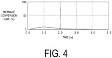
- FIGS. 3 to 5 show the experimental results of Example 1 and Comparative Examples 1 and 2 , respectively.
- FIG. 3 shows the change over time of the concentrations of methane and hydrogen in an effluent gas and the change over time of a methane conversion rate.
- FIGS. 4 and 5 each show the change over time of a methane conversion rate.
- the methane conversion rate is defined by the following equation (2).
- Comparative Example 1 the methane conversion rate rapidly increased immediately after the start of the experiment, and then decreased from around 1 hour after the start of the experiment.
- Comparative Example 2 the methane conversion rate was substantially constant until 1 hour after the start of the experiment, and then the methane conversion rate decreased.
- Example 1 Although it took about 7 hours for the methane conversion rate to increase to the maximum value, after that, the methane conversion rate was substantially constant until 14 hours after the start of the experiment.
- 14 hours after the start of the experiment the supply of argon was stopped, the supply amount of methane was increased, and the flow rate of the feed gas was maintained at 100 cc/min such that the composition of the feed gas was changed to 100% methane. Then, the experiment was terminated at a timing of 20 hours after the start of the experiment.
- FIG. 6A and FIG. 6B show the photographs of the catalyst before the start of the experiment and after the end of the experiment in Example 1, respectively. While the height of a catalyst layer before the start of the experiment was 1.0 cm, the height of the catalyst layer after the end of the experiment increased to about 10.5 cm. This is because carbon as a product of the reaction represented by the reaction formula (1) adhered to the catalyst to increase the volume of the catalyst, and it was confirmed that the carbon was also produced in an amount corresponding to the amount of hydrogen produced.
- the inventors of the present disclosure consider that the catalyst in Example 1 functions by a mechanism different from the mechanism of the conventional supported catalyst used in Comparative Examples 1 and 2. That is, it is considered that when a conventional supported catalyst is used, the catalysis starts working immediately after the start of the experiment, but produced carbon covers active sites of the catalyst so that methane cannot reach the active sites, resulting in a decrease in the activity at an early stage. On the other hand, when a catalyst made of iron powder as in Example 1 is used, it is considered that even when produced carbon adheres to the surface of the iron powder as in Comparative Examples 1 and 2, the activity is maintained because new active sites are developed.
- the mechanism of the catalysis in Example 1 will be described in detail.
- the activity of the catalyst is very low, and thus the reaction rate of the reaction represented by the reaction formula (1) is very low. Then, this reaction gradually begins to occur to produce hydrogen and carbon.
- a grain boundary 31 is generated at the catalyst particle 30 by hydrogen attack. Starting from the grain boundary 31, microparticles of iron move from the catalyst particle 30 by migration and react with the produced carbon to form an iron carbide 32.
- the iron carbide 32 serves as an active site of the catalyst. As the number of such active sites at the catalyst particle 30 gradually increases, the activity of the reaction represented by the reaction formula (1) increases.
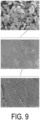
- FIGS. 8 and 9 photographs of the surfaces of the catalyst particle 30 taken in the first stage and the second stages are shown in FIGS. 8 and 9 , respectively.
- the first stage as shown in FIG. 8 , no microparticle of iron is not confirmed at a particle of the catalyst, and a smooth surface peculiar to austenite is observed.
- the second stage as shown in FIG. 9 , a stripe pattern on the order of submicron can be confirmed at a particle of the catalyst. From this, it is considered that conversion of the iron into iron carbides proceeds in association with the hydrogen attack, the iron is divided into iron microparticles on the order of submicron, and precursors of active sites are formed.
- FIG. 10 photographs of the surface of the catalyst particle 30 taken in the fourth stage are shown in FIG. 10 .
- the iron microparticles on the order of submicron are considered to be iron carbides (cementite (Fe 3 C)/martensite (Fe 1.88 C 0.12 )) as active sites. It is considered that the carbon present around the iron carbides has a function as a carrier of an active site and contributes to stabilization of active sites and enhancement of performance.
- FIG. 11A and FIG. 11B An X-ray diffraction pattern of the catalyst particle 30 in a state of the first stage and an X-ray diffraction pattern of the catalyst particle 30 in a state of the fourth stage are shown in FIG. 11A and FIG. 11B , respectively. While only peaks of ⁇ -Fe (ferrite) of the single iron forming the catalyst particle 30 are observed in the state of the first stage, in the state of the fourth stage, not only peaks of ⁇ -Fe (ferrite), but also respective peaks of graphite and martensite (Fe 1.88 C 0.12 ) can be confirmed. This result also confirms the presence of iron carbides and supports that active sites are iron microparticles (iron carbides) on the order of submicron.
- the fifth stage does not necessarily occur after the fourth stage, in the fifth stage, the carbon 33 is peeled off from the catalyst particle 30 naturally or by the action of a physical force. Then, the iron carbide 32 as an active site disappears from the catalyst particle 30, but since the iron carbide 32 continuously appears from the catalyst particle 30, active sites do not rapidly decrease.
- Such a mechanism from the first stage to the fourth stage can sufficiently explain the characteristics of the experimental result of Example 1, that is, a fact that the activity of the reaction slowly increased until 5 hours after the start of the experiment and, thereafter, the activity of the reaction was stable for a long time. It is confirmed that, by this reaction, the iron powder having a particle size of 43 ⁇ m or less was micronized to produce fine iron particles on the order of submicron.
- Example 2 3 4 Reaction temperature (°C) 900 800 750 Amount of catalyst (cc) 0.2 0.2 0.2 Height of catalyst layer (cm) 0.1 0.1 0.1 Flow rate of feed gas (cc/min) 20 20 20 Space velocity (h -1 ) 6000 6000 6000 Composition of feed gas Methane: 100 vol%
- FIG. 12 shows the changes over time of methane conversion rates. According to a magnitude relationship between the methane conversion rates of Examples 2 to 4, it can be said that the higher the reaction temperature is, the higher the peak value of the methane conversion rate is and the shorter the time until the peak value is reached is.
- Example 4 the methane conversion rate reached the maximum values within 20 hours after the start of the experiment and then started to decrease.
- the methane conversion rate increased very gradually until 40 hours after the start of the experiment and then decreased very gradually.
- Example 1 As described above, it was found that the activity of the reaction represented by the reaction formula (1) was maintained for a considerably long time in Examples 2 to 4 as in Example 1. From this, it is considered that in a reaction temperature range of 750°C to 900°C, the iron powder which is the metal particles used as the catalyst was micronized to produce fine iron particles on the order of submicron as in Example 1.
- Example 3 to evaluate a behavior of producing fine iron particles on the order of submicron, a surface image of the iron powder was captured by a scanning electron microscope (SEM) before the start of the experiment, 5 hours after the start of the experiment (corresponding to the second stage of the reaction), 10 hours after the start of the experiment (corresponding to the third stage of the reaction), and 30 hours after the start of the experiment (corresponding to the fourth stage of the reaction). The photographs thereof are shown in FIGS. 13 to 16 .
- SEM scanning electron microscope
- a particle size distribution of the iron powder was obtained before the start of the experiment, 5 hours after the start of the experiment (corresponding to the second stage of the reaction), 10 hours after the start of the experiment (corresponding to the third stage of the reaction), and 30 hours after the start of the experiment (corresponding to the fourth stage of the reaction), and the results thereof were evaluated.
- the particle size distribution was obtained by image analysis of the captured SEM photographs ( FIGS. 13 to 16 ) in accordance with the steps (A) to (E) below.
- the change over time of the methane conversion rate in each of Examples 2 to 4 transitions so as to increase while decreasing the content ratio of the metal in the catalyst or while increasing the content ratio of the carbon in the catalyst and decrease after reaching a peak.
- the metal exhibits catalytic activity in a state of being complexed with carbon, and it is considered that this state contributes to improvement of the catalytic activity.
- Examples 2 to 4 the methane conversion rate exhibited a behavior of increasing after the start of the experiment and decreasing after the methane conversion rate reached a peak. Although the change over time of the methane conversion rates of Examples 5 to 7 are not shown, Examples 5 to 7 also exhibited the same behavior. That is, a peak value of the methane conversion rate was present in each of Examples 2 to 7.
- FIG. 18 shows a relationship between reaction temperature and peak value of the methane conversion rate in Examples 2 to 7.
- FIG. 19 illustrates a metallographic phase diagram of a carbon steel in an equilibrium state (reference source: https://www.monotaro.com/s/pages/readingseries/kikaibuhinhyomensyori_0105 /).
- an iron phase changes to ⁇ -Fe (austenite) at 727°C or higher. Therefore, it is considered that during the reaction represented by the reaction formula (1), iron in the catalyst is in an austenite state, and thus the iron reacts with methane in a feed gas to form iron carbides, and the iron carbides serve as active sites to develop new active sites.
- the reaction temperature is 727°C or higher, the iron powder is micronized to produce fine iron particles on the order of submicron.
- Examples 8 to 11 were performed by using the experimental apparatus 20 illustrated in FIG. 2 .
- the respective experimental conditions for Examples 8 to 11 are summarized in Table 6 below.
- the reaction temperature, the amount of catalyst, the height of catalyst layer, the flow rate of feed gas, and the space velocity for Examples 8 to 11 are the same as those for Examples 2 to 4, and the catalyst used in Examples 8 to 11 is the same as the catalyst used in Examples 1 to 7.
- Example 8 9 10 11 Partial pressure of methane (MPa) 0.025 0.05 0.075 0.1 Composition of feed gas (a) 25 vol% (a) 50 vol% (a) 75 vol% (a) 100 vol% (a) Methane (b) 75 vol% (b) 50 vol% (b) 25 vol% (b) 0 vol% (b) Argon
- FIG. 20 shows a relationship between partial pressure of methane and peak value of methane conversion rate in Examples 8 to 11. According to FIG. 20 , it was found that, at a partial pressure of methane of 0.025 MPa to 0.1 MPa, a peak value of the methane conversion rate gradually decreases as the partial pressure of methane increases.
- the peak value of the methane conversion rate is a little less than 60% when the partial pressure of methane is 0.025 MPa and the peak value of the methane conversion rate is a little less than 50% when the partial pressure of methane is 0.1 MPa, it can be said that the influence of the partial pressure of methane on the peak value of the methane conversion rate is small when the partial pressure of methane is within the above-described range. Since it was found from Examples 1 to 4 that when iron powder is used as a catalyst, the activity of the reaction represented by the reaction formula (1) is maintained for a considerably long time, the activity of the reaction represented by the reaction formula (1) is supposed to be maintained for a long time also in Examples 8 to 11.
- the iron powder used as a catalyst of the reaction is micronized to produce fine iron particles on the order of submicron. Therefore, it is considered that a reaction of decomposing methane into hydrogen and carbon is caused by bringing the methane into contact with the iron powder at a temperature of 600°C to 900°C when the partial pressure of methane is from 0.025 MPa to 0.1 MPa, and the iron powder is micronized by the reaction to produce fine iron particles on the order of submicron.
- the catalyst for Example 12 is iron powder available from Kojundo Chemical Laboratory Co., Ltd., and the iron powder having a particle size in the range of 0.04 to 0.15 mm was selected by a sieve and used.
- the catalyst for Example 13 is iron particles available from Kojundo Chemical Laboratory Co., Ltd., and the iron particles having a particle size in the range of 2 to 3 mm was selected by a sieve and used.
- the respective catalysts for Examples 14 and 15 are carbonyl iron powders available from Kojundo Chemical Laboratory Co., Ltd.
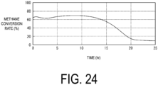
- Example 12 The experimental results of Examples 12 to 15 are shown in FIG. 21 to 24 , respectively.
- the maximum value of the methane conversion rate did not reach substantially 90% unlike Example 1, and the methane conversion rate exhibited a behavior of gradually increasing, reaching the maximum value, and then gradually decreasing although the timing was different between respective Examples.
- the methane conversion rate reached the maximum value about 18 hours after the start of the experiment, and as shown in FIG. 22 , in Example 13, the methane conversion rate reached the maximum value about 51 hours after the start of the experiment.
- the methane conversion rate reached the maximum value about 1 hour after the start of the experiment as shown in FIGS. 23 and 24 , respectively.
- Example 16 using nickel particles as a catalyst was performed by using the experimental apparatus 20 illustrated in FIG. 2 .
- the experimental conditions for Example 16 are the same as the experimental conditions for Example 3.
- the nickel particles are available from The Nilaco Corporation and the particle size thereof is in the range of 2 to 40 ⁇ m.
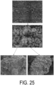
- FIG. 25 shows photographs of surface images of the nickel particles taken by a scanning electron microscope before the start of the experiment
- FIG. 26 shows photographs of surface images of the nickel particles taken by a scanning electron microscope 50 hours after the start of the experiment. While the particle size of the nickel particles before the start of the experiment was at a level of several ⁇ m, the particle size of the nickel particles became several nm to several tens of nm 50 hours after the start of the experiment. Thus, it was found that the method of the present disclosure can be applied to not only iron but also nickel to micronize nickel.
- iron and nickel can be micronized by applying the method of the present disclosure
- the inventors of the present disclosure consider that cobalt can also be micronized by applying the method of the present disclosure for the reason below, although no experiment for this has been performed.
- metals are classified from the viewpoint of catalysis on the thermal decomposition of hydrocarbon compounds, it is known that, for example, titanium, zirconium, and tantalum belong to a group forming stable carbides, copper, silver, gold, platinum, and palladium belong to a group having no activity because a stable carbon-metal bond cannot be expected, and iron, nickel, and cobalt belong to a group having high activity.
- the inventors of the present disclosure consider that the method of the present disclosure can also be applied to cobalt to micronize the cobalt.
- the inventors of the present disclosure consider that not only iron, nickel, and cobalt as a single component, but also an alloy of at least two of iron, nickel, or cobalt can be micronized by applying the method of the present disclosure.
- Example 17 using iron particles subjected to hydrogen treatment
- Comparative Example 3 using iron particles not subjected to hydrogen treatment
- the iron particles used in Example 17 and Comparative Example 3 are electrolytic iron that is available from The Nilaco Corporation and has an iron purity of 99 mass% and an average particle size of 45 ⁇ m.
- the hydrogen treatment in Example 17 was performed by supplying a gas of 20 vol% hydrogen and 80 vol% argon at 800°C to the iron particles at a space velocity of 6000 (h -1 ) for 2 hours.
- the conditions for the subsequent experiment are the same as the conditions for Example 3.
- FIG. 27 shows the respective experimental results of Example 17 and Comparative Example 3, that is, the transitions of the methane conversion rates thereof.
- the methane conversion rate in Example 17 using the iron particles subjected to the hydrogen treatment is higher than the methane conversion rate in Comparative Example 3 using the iron particles not subjected to the hydrogen treatment. From this, it is expected that the hydrogen treatment promotes the micronization of iron, that is, the micronization of metal.
- the inventors of the present disclosure consider that when hydrogen is supplied to metal particles, grain boundaries are generated in the metal particles due to hydrogen attack, and microparticles of iron move from catalyst particles by migration starting from the grain boundaries, whereby the progress of the micronization of metal is promoted.
- Examples 18 and 19 using iron particles subjected to carbon monoxide treatment and an experiment of Comparative Example 4 using iron particles not subjected to carbon monoxide treatment were performed by using the experimental apparatus 20 illustrated in FIG. 2 .
- the iron particles used in Examples 18 and 19 and Comparative Example 4 are electrolytic iron that is available from The Nilaco Corporation and has an iron purity of 99 mass% and an average particle size of 36 ⁇ m.
- hydrogen treatment was also performed after the carbon monoxide treatment.
- Example 19 only the carbon monoxide treatment was performed.
- the conditions for the carbon monoxide treatment for Examples 18 and 19, the conditions for the hydrogen treatment for Example 18, and the conditions for micronization experiments for Examples 18 and 19 and Comparative Example 4 are summarized in Table 8 below.
- FIG. 28 shows the respective experimental results of Examples 18 and 19 and Comparative Example 4, that is, the transitions of the methane conversion rates thereof. It was found that in each of Examples 18 and 19, the degree of increase in the methane conversion rate after the start of the experiment was larger than that in Comparative Example 4. It was also found that the methane conversion rate of Example 18 was higher than that of Comparative Example 4 until about 12 hours after the start of the experiment, and the methane conversion rate of Example 19 was higher than that of Comparative Example 4 until about 15 hours after the start of the experiment. From this, it is expected that the carbon monoxide treatment promotes the micronization of iron, that is, the micronization of metal. The inventors of the present disclosure consider that when carbon monoxide is supplied to metal particles, carbon is deposited by a reaction of converting the carbon monoxide into carbon and carbon dioxide on the surfaces of the metal particles, whereby the progress of the micronization of metal is promoted.
Landscapes
- Chemical & Material Sciences (AREA)
- Organic Chemistry (AREA)
- Engineering & Computer Science (AREA)
- Chemical Kinetics & Catalysis (AREA)
- Materials Engineering (AREA)
- Thermal Sciences (AREA)
- Inorganic Chemistry (AREA)
- Physics & Mathematics (AREA)
- Health & Medical Sciences (AREA)
- Combustion & Propulsion (AREA)
- General Health & Medical Sciences (AREA)
- General Chemical & Material Sciences (AREA)
- Catalysts (AREA)
- Manufacture Of Metal Powder And Suspensions Thereof (AREA)
- Powder Metallurgy (AREA)
- Organic Low-Molecular-Weight Compounds And Preparation Thereof (AREA)
Applications Claiming Priority (2)
| Application Number | Priority Date | Filing Date | Title |
|---|---|---|---|
| JP2021177811A JP7291191B2 (ja) | 2021-10-29 | 2021-10-29 | 微細金属粒子の製造方法 |
| PCT/JP2022/034370 WO2023074167A1 (ja) | 2021-10-29 | 2022-09-14 | 微細金属粒子の製造方法 |
Publications (2)
| Publication Number | Publication Date |
|---|---|
| EP4403281A1 true EP4403281A1 (de) | 2024-07-24 |
| EP4403281A4 EP4403281A4 (de) | 2025-01-22 |
Family
ID=86157829
Family Applications (1)
| Application Number | Title | Priority Date | Filing Date |
|---|---|---|---|
| EP22886501.0A Pending EP4403281A4 (de) | 2021-10-29 | 2022-09-14 | Herstellungsverfahren für feine metallpartikel |
Country Status (8)
| Country | Link |
|---|---|
| US (1) | US20240416415A1 (de) |
| EP (1) | EP4403281A4 (de) |
| JP (1) | JP7291191B2 (de) |
| KR (1) | KR20240063944A (de) |
| CN (1) | CN118139706A (de) |
| AU (1) | AU2022379089B2 (de) |
| TW (1) | TWI814581B (de) |
| WO (1) | WO2023074167A1 (de) |
Citations (1)
| Publication number | Priority date | Publication date | Assignee | Title |
|---|---|---|---|---|
| US20050123467A1 (en) | 2003-12-03 | 2005-06-09 | Avetik Harutyunyan | Systems and methods for production of carbon nanostructures |
Family Cites Families (10)
| Publication number | Priority date | Publication date | Assignee | Title |
|---|---|---|---|---|
| JP3822022B2 (ja) * | 2000-05-17 | 2006-09-13 | 株式会社日本製鋼所 | 炭化水素分解材料および炭化水素分解装置 |
| CA2545879C (en) * | 2003-11-21 | 2011-09-20 | Statoil Asa | Method for conversion of hydrocarbons |
| ITRM20040502A1 (it) * | 2004-10-13 | 2005-01-13 | Univ Roma Tor Vergata | Produzione simultanea di nanotubi di carbonio ed idrogeneo molecolare. |
| JP4697941B2 (ja) * | 2005-05-11 | 2011-06-08 | 株式会社日本製鋼所 | 低級炭化水素の直接分解による機能性ナノ炭素及び水素の製造方法 |
| JP5409345B2 (ja) * | 2007-03-14 | 2014-02-05 | 公立大学法人大阪府立大学 | ブラシ状カーボンナノ構造物製造用触媒体、その製造方法及びブラシ状カーボンナノ構造物製造方法 |
| JP4819083B2 (ja) * | 2008-04-11 | 2011-11-16 | 株式会社日本製鋼所 | 無担持炭化水素直接分解触媒 |
| KR101917103B1 (ko) * | 2017-02-10 | 2018-11-09 | 한국과학기술연구원 | 다공성 니켈-알루미늄 합금 분말, 이를 이용한 촉매 및 그 제조 방법 |
| JP6871600B2 (ja) | 2017-02-28 | 2021-05-12 | 学校法人立命館 | 金属材料の製造方法、及び、金属材料 |
| JP2021138562A (ja) * | 2020-03-03 | 2021-09-16 | 国立大学法人京都大学 | 水素の製造方法 |
| JP7390661B2 (ja) | 2020-05-11 | 2023-12-04 | 株式会社丸山製作所 | シャワーノズル及び液体流通構造 |
-
2021
- 2021-10-29 JP JP2021177811A patent/JP7291191B2/ja active Active
-
2022
- 2022-09-14 WO PCT/JP2022/034370 patent/WO2023074167A1/ja not_active Ceased
- 2022-09-14 US US18/703,904 patent/US20240416415A1/en active Pending
- 2022-09-14 CN CN202280069502.2A patent/CN118139706A/zh active Pending
- 2022-09-14 KR KR1020247011504A patent/KR20240063944A/ko active Pending
- 2022-09-14 EP EP22886501.0A patent/EP4403281A4/de active Pending
- 2022-09-14 AU AU2022379089A patent/AU2022379089B2/en active Active
- 2022-09-19 TW TW111135349A patent/TWI814581B/zh active
Patent Citations (1)
| Publication number | Priority date | Publication date | Assignee | Title |
|---|---|---|---|---|
| US20050123467A1 (en) | 2003-12-03 | 2005-06-09 | Avetik Harutyunyan | Systems and methods for production of carbon nanostructures |
Also Published As
| Publication number | Publication date |
|---|---|
| EP4403281A4 (de) | 2025-01-22 |
| US20240416415A1 (en) | 2024-12-19 |
| AU2022379089B2 (en) | 2025-07-03 |
| JP7291191B2 (ja) | 2023-06-14 |
| CN118139706A (zh) | 2024-06-04 |
| KR20240063944A (ko) | 2024-05-10 |
| TWI814581B (zh) | 2023-09-01 |
| TW202328463A (zh) | 2023-07-16 |
| JP2023066934A (ja) | 2023-05-16 |
| AU2022379089A1 (en) | 2024-05-02 |
| WO2023074167A1 (ja) | 2023-05-04 |
Similar Documents
| Publication | Publication Date | Title |
|---|---|---|
| JP7089235B1 (ja) | 炭化水素の直接分解装置及び直接分解方法 | |
| JP4257690B2 (ja) | 粉末冶金用途のための焼結活性金属粉末及び合金粉末、それらの製造方法並びにそれらの使用 | |
| JP3721014B2 (ja) | スッパタリング用タングステンターゲットの製造方法 | |
| CA2470945A1 (en) | Regeneration of catalysts for carbon monoxide hydrogenation | |
| CN115382541A (zh) | 一种调控铑基催化剂中Rh物种存在形式的方法 | |
| CA2472607A1 (en) | Catalyst enhancement | |
| JPH07116517A (ja) | メタノール改質用触媒およびその製造方法並びにメタノールの改質法 | |
| CN1167615C (zh) | 通过气相渗碳制造碳化钨的方法 | |
| JP2003524069A (ja) | 金属または金属酸化物を形成するための金属含有化合物の迅速な変換 | |
| CN114082438B (zh) | 一种负载型氮掺杂金属基介孔分子筛催化剂及其制备方法和应用 | |
| CA2419766A1 (en) | Fischer-tropsch process | |
| EP3351509B1 (de) | Intermetallische laves-phasen-verbindung, katalysator mit der intermetallischen verbindung und verfahren zur herstellung von ammoniak | |
| EP3766835A1 (de) | Elektronen- oder hydridionenabsorbierendes/-desorbierendes material, elektronen- oder hydridionenabsorbierende/-desorbierende zusammensetzung, übergangsmetallträger und katalysator und deren verwendung | |
| US20240416415A1 (en) | Production method for fine metal particles | |
| JP2000203825A (ja) | 純粋な炭化タングステン粉末を製造するための気体浸炭方法 | |
| CN1289391C (zh) | 碳化钨、其制备方法和由其制得的硬质材料 | |
| JP3336948B2 (ja) | 金属微粉末の製造方法 | |
| TWI859757B (zh) | 微細金屬粒子之製造方法 | |
| CA2417591A1 (en) | Carbon monoxide hydrogenation | |
| CA2420963A1 (en) | Carbon monoxide hydrogenation process | |
| EP4480907A1 (de) | Verfahren und vorrichtung zur rückgewinnung von kohlenstoff aus kohlenstoffhaltigem gas | |
| Fukushima et al. | Thermal Stability and CO Oxidation Property of Non-Equilibrium Pd–Ru Alloy Catalyst | |
| CN115282969B (zh) | 一种磁性NiFe2O4纳米球的制备方法及应用 | |
| CN120460721A (zh) | 一种铁钴镍基高熵合金纳米颗粒、制备方法及应用 | |
| JP2025144499A (ja) | セメンタイトの製造方法 |
Legal Events
| Date | Code | Title | Description |
|---|---|---|---|
| STAA | Information on the status of an ep patent application or granted ep patent |
Free format text: STATUS: THE INTERNATIONAL PUBLICATION HAS BEEN MADE |
|
| PUAI | Public reference made under article 153(3) epc to a published international application that has entered the european phase |
Free format text: ORIGINAL CODE: 0009012 |
|
| STAA | Information on the status of an ep patent application or granted ep patent |
Free format text: STATUS: REQUEST FOR EXAMINATION WAS MADE |
|
| 17P | Request for examination filed |
Effective date: 20240416 |
|
| AK | Designated contracting states |
Kind code of ref document: A1 Designated state(s): AL AT BE BG CH CY CZ DE DK EE ES FI FR GB GR HR HU IE IS IT LI LT LU LV MC MK MT NL NO PL PT RO RS SE SI SK SM TR |
|
| RAP3 | Party data changed (applicant data changed or rights of an application transferred) |
Owner name: MITSUBISHI HEAVY INDUSTRIES, LTD. |
|
| A4 | Supplementary search report drawn up and despatched |
Effective date: 20250102 |
|
| RIC1 | Information provided on ipc code assigned before grant |
Ipc: B22F 1/052 20220101ALN20241218BHEP Ipc: C01B 3/30 20060101ALI20241218BHEP Ipc: C01B 3/26 20060101ALI20241218BHEP Ipc: B01J 23/745 20060101ALI20241218BHEP Ipc: B22F 1/16 20220101ALI20241218BHEP Ipc: B22F 1/145 20220101ALI20241218BHEP Ipc: B22F 1/142 20220101ALI20241218BHEP Ipc: B22F 9/04 20060101AFI20241218BHEP |
|
| DAV | Request for validation of the european patent (deleted) | ||
| DAX | Request for extension of the european patent (deleted) | ||
| STAA | Information on the status of an ep patent application or granted ep patent |
Free format text: STATUS: EXAMINATION IS IN PROGRESS |
|
| 17Q | First examination report despatched |
Effective date: 20251202 |
|
| TPAC | Observations filed by third parties |
Free format text: ORIGINAL CODE: EPIDOSNTIPA |