EP4480907A1 - Verfahren und vorrichtung zur rückgewinnung von kohlenstoff aus kohlenstoffhaltigem gas - Google Patents
Verfahren und vorrichtung zur rückgewinnung von kohlenstoff aus kohlenstoffhaltigem gas Download PDFInfo
- Publication number
- EP4480907A1 EP4480907A1 EP23766644.1A EP23766644A EP4480907A1 EP 4480907 A1 EP4480907 A1 EP 4480907A1 EP 23766644 A EP23766644 A EP 23766644A EP 4480907 A1 EP4480907 A1 EP 4480907A1
- Authority
- EP
- European Patent Office
- Prior art keywords
- carbon
- gas
- containing gas
- porous material
- recovering
- Prior art date
- Legal status (The legal status is an assumption and is not a legal conclusion. Google has not performed a legal analysis and makes no representation as to the accuracy of the status listed.)
- Pending
Links
Images


Classifications
-
- B—PERFORMING OPERATIONS; TRANSPORTING
- B01—PHYSICAL OR CHEMICAL PROCESSES OR APPARATUS IN GENERAL
- B01J—CHEMICAL OR PHYSICAL PROCESSES, e.g. CATALYSIS OR COLLOID CHEMISTRY; THEIR RELEVANT APPARATUS
- B01J23/00—Catalysts comprising metals or metal oxides or hydroxides, not provided for in group B01J21/00
- B01J23/70—Catalysts comprising metals or metal oxides or hydroxides, not provided for in group B01J21/00 of the iron group metals or copper
- B01J23/74—Iron group metals
- B01J23/745—Iron
-
- C—CHEMISTRY; METALLURGY
- C01—INORGANIC CHEMISTRY
- C01B—NON-METALLIC ELEMENTS; COMPOUNDS THEREOF; METALLOIDS OR COMPOUNDS THEREOF NOT COVERED BY SUBCLASS C01C
- C01B32/00—Carbon; Compounds thereof
- C01B32/05—Preparation or purification of carbon not covered by groups C01B32/15, C01B32/20, C01B32/25, C01B32/30
-
- C—CHEMISTRY; METALLURGY
- C01—INORGANIC CHEMISTRY
- C01B—NON-METALLIC ELEMENTS; COMPOUNDS THEREOF; METALLOIDS OR COMPOUNDS THEREOF NOT COVERED BY SUBCLASS C01C
- C01B32/00—Carbon; Compounds thereof
- C01B32/40—Carbon monoxide
-
- C—CHEMISTRY; METALLURGY
- C01—INORGANIC CHEMISTRY
- C01B—NON-METALLIC ELEMENTS; COMPOUNDS THEREOF; METALLOIDS OR COMPOUNDS THEREOF NOT COVERED BY SUBCLASS C01C
- C01B32/00—Carbon; Compounds thereof
- C01B32/90—Carbides
- C01B32/914—Carbides of single elements
-
- B—PERFORMING OPERATIONS; TRANSPORTING
- B01—PHYSICAL OR CHEMICAL PROCESSES OR APPARATUS IN GENERAL
- B01D—SEPARATION
- B01D2251/00—Reactants
- B01D2251/20—Reductants
- B01D2251/202—Hydrogen
-
- B—PERFORMING OPERATIONS; TRANSPORTING
- B01—PHYSICAL OR CHEMICAL PROCESSES OR APPARATUS IN GENERAL
- B01D—SEPARATION
- B01D2255/00—Catalysts
- B01D2255/20—Metals or compounds thereof
- B01D2255/207—Transition metals
- B01D2255/20738—Iron
-
- B—PERFORMING OPERATIONS; TRANSPORTING
- B01—PHYSICAL OR CHEMICAL PROCESSES OR APPARATUS IN GENERAL
- B01D—SEPARATION
- B01D2257/00—Components to be removed
- B01D2257/50—Carbon oxides
- B01D2257/502—Carbon monoxide
Definitions
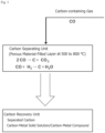
- the present invention relates to a method and an apparatus for recovering carbon from a carbon-containing gas containing carbon monoxide.
- the present invention relates to a method and an apparatus for recovering, from a carbon-containing gas containing carbon monoxide included in a blast furnace gas, an exhaust gas, or the like discharged in various industries, carbon from the carbon-containing gas.
- Examples of a method for reducing carbon dioxide contained in an exhaust gas include either one of a method of replacing an industrial process that generates carbon dioxide with a process that does not involve the use of carbon, or a method of removing carbon from an exhaust gas containing carbon dioxide.
- a method of removing from an exhaust gas carbon dioxide as is or as a carbon compound (e.g., hydrocarbon) other than carbon dioxide has been the mainstream.
- Patent Literature 1 discloses a method for producing a carbonate ester using a catalytic structure for producing a carbonate ester, and discloses the production of a carbonate ester by a reaction between a monohydric alcohol and carbon dioxide in the presence of the catalytic structure and a hydration agent.
- Patent Literature 2 discloses a method for separating carbon dioxide as is from a target gas to be treated by bringing the gas into direct contact with an adsorbent in a reaction vessel that is supplied with water and discharges water.
- the method for separating carbon dioxide from a target gas to be treated described in Patent Literature 2 includes washing the adsorbent, which has its carbon dioxide adsorption capacity decreased by poisoning, with water, thereby washing away a poisoning component (e.g., an acid or a metal salt) attached to the adsorbent so that the adsorbent surface can thus be exposed. This allows the carbon dioxide adsorption capacity of the adsorbent to be recovered.
- a poisoning component e.g., an acid or a metal salt
- Non Patent Literature 1 Materials Transactions, Vol. 58, No. 12 (2017), pp. 1742 to 1748 "Development of Manufacturing Principle of Porous Iron by Carbothermic Reduction of Composite of Hematite and Biomass Char "
- the technology for reducing carbon dioxide such as the technology for producing a carbonate ester disclosed in each of Patent Literatures 1 and 2
- the technology for reducing carbon dioxide is intended to separate and remove carbon dioxide as is, or as a carbon compound, but cannot recover carbon itself contained in the carbon dioxide.
- a carbon dioxide gas can be reformed into carbon monoxide through a water-gas shift reaction. Therefore, if there is any method that can recover carbon from carbon monoxide, it will be possible to recover carbon from carbon dioxide by combining the reaction with a water-gas shift reaction.
- there has been proposed no method that can recover carbon from carbon monoxide which is problematic.
- the present invention has been made in view of the above circumstances and aims to provide a method and an apparatus for recovering carbon from a carbon-containing gas that can recover carbon contained in a carbon monoxide gas and thus recycle the carbon.
- a method for recovering carbon from a carbon-containing gas according to the present invention that advantageously solves the above problems includes a step of bringing a carbon-containing gas, which contains carbon monoxide and satisfies Expression (1), into contact with a porous material to cause carbon to be separated from the carbon monoxide, and a step of recovering the carbon.
- Expression 1 H 2 O / H 2 O + H 2 ⁇ 0.1 , where [H 2 O] represents a water concentration (volume%) in a reformed mixed gas, and [H 2 ] represents a hydrogen concentration (volume%) in the reformed mixed gas.
- an apparatus for recovering carbon from a carbon-containing gas includes: (j) a carbon separating unit that brings a carbon-containing gas containing carbon monoxide into contact with a porous material to cause carbon to be separated from the carbon monoxide, and a carbon recovery unit that recovers the carbon.
- the present invention it is possible to recover carbon that forms carbon monoxide contained in a carbon-containing gas, and thus recycle the carbon. Further, according to the present invention, it is possible to recover carbon from carbon dioxide by using a gas obtained by reforming carbon dioxide contained in an exhaust gas, a blast furnace gas, or the like into carbon monoxide through a reaction combined with a water-gas shift reaction.
- the method for recovering carbon from a carbon-containing gas according to a first embodiment includes a step of bringing a carbon-containing gas containing carbon monoxide into contact with a porous material to cause carbon to be separated from the carbon monoxide, and a step of recovering the carbon.
- Fig. 1 is a schematic view of an example of a process of a carbon recovery method for recovering solid-state carbon from a carbon-containing gas according to the present embodiment. It is acceptable as long as the carbon-containing gas contains carbon monoxide as a raw material of carbon to be recovered, and the carbon-containing gas may also contain carbon dioxide, hydrogen, water, and so on in addition to the carbon monoxide. It should be noted that the water and hydrogen contained in the carbon-containing gas need to satisfy the following Expression (1).
- the carbon-containing gas used for the carbon recovery method for recovering solid-state carbon from a carbon-containing gas of the present embodiment may be an exhaust gas or a gas generated in the existing production process, such as a blast furnace gas.
- the carbon-containing gas contains carbon monoxide, carbon dioxide, hydrogen, and water in many cases.
- the carbon monoxide contained in the carbon-containing gas becomes a raw material of carbon to be recovered.
- the carbon that forms the carbon monoxide contained in the carbon-containing gas is separated from the carbon monoxide by a bimolecular decomposition reaction (I) that occurs with the decomposition of two carbon monoxide molecules represented by the following Chemical Equation (I), or by a monomolecular decomposition reaction (II) that occurs with a reaction between one carbon monoxide molecule and hydrogen represented by the following Chemical Equation (II).
- CO/(CO + CO 2 ) is preferably 0.5 or more, and is more preferably 0.7 or more. Accordingly, solid-state carbon can be efficiently recovered from the carbon monoxide.
- the carbon-containing gas may be prepared by supplying gas components, such as carbon monoxide, carbon dioxide, and hydrogen, from vessels filled with the respective gas components so that they attain their predetermined volume percent.
- the carbon-containing gas may be a blast furnace gas discharged from an iron-making blast furnace, or an exhaust gas discharged from an automobile, a gas turbine, an incinerator, a thermal power plant, or a factory as long as the carbon-containing gas contains a predetermined amount of carbon monoxide.
- the carbon-containing gas may be a gas obtained by using a blast furnace gas or an exhaust gas as a raw material, and adding thereto deficient gas components to adjust the amounts of carbon monoxide and carbon dioxide so that they attain the above volume percent.
- the carbon-containing gas may be a gas obtained by using a blast furnace gas or an exhaust gas as a raw material, and chemically treating the gas to adjust the amounts of carbon monoxide and carbon dioxide so that they attain the above volume percent.
- a blast furnace gas contains 21 to 23 volume% carbon monoxide, 19 to 22 volume% carbon dioxide, 2 to 3 volume% hydrogen, and 53 to 56 volume% nitrogen and can be directly used as the carbon-containing gas.
- a blast furnace gas is generated as coke, heavy oil, and pulverized coal, which have been fed into a blast furnace, are partially combusted with air to produce a reducing gas that is composed mainly of carbon monoxide and nitrogen, and then iron ores are reduced with the reducing gas. Therefore, by appropriately setting the combustion conditions for coke and so on in the blast furnace, the volume percent of each gas component in the blast furnace gas can be adjusted. In addition, by appropriately setting the combustion conditions for a fuel as a raw material of the exhaust gas, the volume percent of each gas component in the exhaust gas can be adjusted.
- Bringing the carbon-containing gas into contact with the porous material and separating carbon from the carbon monoxide contained in the carbon-containing gas are performed within a carbon separating unit of a carbon recovery apparatus adopted to implement the method for recovering carbon according to the present embodiment.
- a filled layer filled with the porous material is provided in the carbon separating unit.
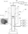
- Fig. 2 is a schematic view showing an overview of a carbon separating unit provided in a carbon recovery apparatus adopted to implement the method for recovering carbon according to the present embodiment.
- a reaction tower 101 provided in a carbon separating unit 100 in the carbon recovery apparatus is filled with a porous material 102.
- the porous material 102 is held by a sample holder 101a provided within the reaction tower 101.
- the configuration of the porous material 102 is not limited to a particular one as long as it allows a decomposition reaction of the carbon monoxide contained in the carbon-containing gas to proceed as the carbon-containing gas passes through the porous material 102.
- the configuration of the porous material 102 may be a porous material formed into a tablet shape as shown in Fig.
- a carbon-containing gas containing carbon monoxide is supplied from a lower portion of the reaction tower 101 provided in the carbon separating unit 100.
- the carbon-containing gas supplied to the reaction tower 101 comes into contact with the porous material 102 provided within the reaction tower 101 as it passes through the porous material 102.
- the contact between the carbon monoxide contained in the carbon-containing gas and the porous material 102 is preferably effected under an atmosphere of a predetermined temperature and a predetermined pressure in the carbon separating unit 100. Therefore, the carbon separating unit 100 may include a temperature control device, such as a heater, for setting the internal space of the carbon separating unit 100 to be in a predetermined temperature range.
- the carbon-containing gas containing carbon monoxide is supplied from a supply pipe 104 disposed in the lower portion of the reaction tower 101.
- An off-gas resulting from the contact between the carbon-containing gas containing carbon monoxide and the porous material 102 is discharged through an exhaust gas pipe 105.
- the contact between the carbon-containing gas and the porous material 102 is preferably effected under an atmosphere in the temperature range of 500 to 800°C.
- the temperature at which the carbon-containing gas is brought into contact with the porous material 102 is 500°C or higher, a decomposition reaction of the carbon monoxide is promoted, which is preferable, while when the temperature is 800°C or lower, the thermal energy generated by a decomposition reaction of the carbon monoxide can be effectively utilized, which is preferable.
- the range of the temperature at which the carbon-containing gas is brought into contact with the porous material 102 includes 500 to 800°C that corresponds to the temperature condition adopted for direct-reduction ironmaking performed by using iron as the porous material 102, for example.
- the contact between the carbon-containing gas and the porous material 102 is preferably effected under an atmosphere at 1.0 to 10 atm.
- the pressure of 1.0 atm or more at which the carbon-containing gas is brought into contact with the porous material 102 corresponds to the pressurization condition, and allows the chemical equilibriums of the decomposition reactions of the carbon monoxide represented by Chemical Equations (I) and (II) to shift in the direction in which carbon is separated, thus promoting the decomposition reactions of the carbon monoxide, which is preferable.
- the pressure of 10 atm or less at which the carbon-containing gas is brought into contact with the porous material 102 can ensure the safety when the carbon separating unit 100 is operated in terms of the legal restraints, which is preferable.
- the porous material 102 with which the carbon-containing gas containing carbon monoxide is brought into contact, preferably has an open porosity of 50% to 99%, more preferably 80% or more.
- the open porosity is measured by the Archimedes method.
- the carbon-containing gas containing carbon monoxide passes through the pores of the porous material 102, and a decomposition reaction of the carbon monoxide is promoted, and thus, carbon can be separated from the carbon monoxide, which is preferable.
- the carbon separated from the carbon monoxide is adsorbed in the pores of the porous material 102.
- the porous material 102 with which the carbon-containing gas containing carbon monoxide is brought into contact preferably contains at least one element selected from the group consisting of iron, platinum, nickel, cobalt, rhodium, and palladium. That is, the porous material 102 may contain one metal element selected from the group consisting of iron, platinum, nickel, cobalt, rhodium, and palladium, or a combination of two or more of such metal elements. Further, the porous material 102 may be a metal compound containing one metal element selected from the group consisting of iron, platinum, nickel, cobalt, rhodium, and palladium as carbide, oxide, carbonate, sulfate, oxalate, or the like.
- iron, platinum, and nickel are preferable.
- the platinum or nickel functions as a decomposition reaction catalyst for the carbon monoxide, and the decomposition reaction catalyst would undergo little deterioration, which is preferable.
- solid-state carbon is precipitated as graphite alone by a decomposition reaction of the carbon monoxide, which is preferable.
- the porous material 102 with which the carbon-containing gas containing carbon monoxide is brought into contact is more preferably iron.
- the use of iron as the porous material 102 causes the porous material 102 to be carburized by carbon generated by the decomposition reaction of the carbon monoxide to thus obtain austenite (i.e., ⁇ iron) with the carbon being dissolved as a solid-solution, which is preferable.
- the use of iron as the porous material 102 also causes the porous material 102 to be carburized by carbon separated from the carbon monoxide by the decomposition reaction of the carbon monoxide and to be reacted with the iron, obtaining cementite (iron carbide) which is preferable.
- Austenite and cementite resulting from the carburizing of the porous material 102, which is iron, by carbon separated from the carbon monoxide by the decomposition reaction of carbon monoxide have almost the same hardness as quenching steel and thus can be directly used as iron-making raw materials.
- the porous material 102 with which the carbon-containing gas is brought into contact is preferably one or two types of iron selected from the group consisting of iron oxide and reduced iron.
- the porous material 102 with which the carbon-containing gas containing carbon monoxide is brought into contact is particularly preferably an iron whisker.
- An iron whisker is a metallic crystal that grows on the surface of a crystal in an outward direction like a beard and is formed such that, when compression stress is generated around the surface of a crystal, a new crystal is grown on the original crystal in an outward direction in an attempt to relax the stress. Since such an iron whisker has a small start point of crystal growth and tends to keep growing continuously, it is formed as a single crystal in the shape of an extremely long and thin beard and has a length of 10 ⁇ m or more relative to a diameter of about 1 ⁇ m.
- an iron whisker is adopted as the porous material 102 with which the carbon-containing gas containing carbon monoxide is brought into contact, it is possible to allow the iron whisker to be carburized by the carbon separated from the carbon monoxide by a decomposition reaction of the carbon monoxide, thereby obtaining an iron whisker formed of austenite (i.e., ⁇ iron) or an iron whisker formed of cementite (i.e., iron carbide).
- the iron whisker as the porous material 102 with which the carbon-containing gas containing carbon monoxide is brought into contact can be produced by a method of producing an iron whisker described in Non Patent Literature 1, for example. According to the method of producing an iron whisker, it is possible to obtain an iron whisker as the porous material 102 with an open porosity of 90% or more and a pore diameter of 10 ⁇ m or more.
- the iron whisker obtained by the method of producing an iron whisker also has a high open porosity and thus can be preferably used as the porous material 102 used for the method for recovering carbon from a carbon-containing gas of the present embodiment. It should be noted that even when a metal other than iron, such as platinum, is used as the metal for forming the porous material 102 with which the carbon-containing gas is brought into contact, the porous material 102 can be produced in the same manner.
- the carbon obtained by a decomposition reaction of the carbon monoxide contained in the carbon-containing gas is precipitated on the surface of the porous material 102 or on the inner surfaces of the pores of the porous material 102.
- the carbon obtained by a decomposition reaction of the carbon monoxide contained in the carbon-containing gas also causes carburizing within the porous material 102 and reacts with the metal element forming the porous material 102, thereby forming a carbon solid solution or a metal carbide compound. Further, the carbon obtained by a decomposition reaction of the carbon monoxide contained in the carbon-containing gas is precipitated on the surface of the carbon solid solution or the metal carbide compound.
- the step of recovering carbon can be performed using the carbon recovery unit of the carbon recovery apparatus adopted to implement the method for recovering carbon according to the present embodiment.
- the carbon recovery unit recovers carbon separated from the carbon monoxide and precipitated on the surface of the porous material 102.
- the carbon recovery unit may include, for example, a sieve mesh for separating the separated solid-state carbon from the porous material 102.
- the method for recovering carbon from a carbon-containing gas according to the present embodiment bringing a carbon-containing gas containing carbon monoxide into contact with the porous material 102 can promote a decomposition reaction of the carbon monoxide to separate carbon, and recover the carbon as separated solid-state carbon, or as a carbon-metal solid solution or a metal carbide compound containing the carbon.
- the carbon recovery apparatus used for the method for recovering carbon from a carbon-containing gas according to the present embodiment includes the carbon separating unit 100 and the carbon recovery unit, it is possible to recover carbon as solid-state carbon separated from carbon monoxide, or as a carbon solid solution or a metal carbide compound containing the carbon.
- the carbon recovered by the method for recovering carbon from a carbon-containing gas according to the present embodiment can be utilized as, for example, a source of energy for power generation and so on, an auxiliary material fed into a converter for thermal compensation for molten iron, or an iron-making raw material before quenching is performed. That is, the method for recovering carbon from a carbon-containing gas according to the present embodiment allows, by using carbon recovered from a carbon-containing gas containing carbon monoxide, the carbon to be effectively utilized as a recycled resource.
- a method for recovering carbon from a carbon-containing gas according to a second embodiment will be described.
- the method for recovering carbon from a carbon-containing gas according to the present embodiment is characterized in that, in the method for recovering carbon according to the above embodiment, the carbon-containing gas contains carbon monoxide generated by a reforming reaction of a source gas containing carbon dioxide that is effected by heating a mixed gas obtained by supplying hydrogen to the source gas to 800 to 1200°C. That is, each step included in the method for recovering carbon from a carbon-containing gas according to the present embodiment is identical to each step included in the method for recovering carbon according to the first embodiment, except that a carbon-containing gas containing carbon monoxide is prepared from a mixed gas that includes as a raw material a source gas containing carbon dioxide.
- Fig. 3 is a schematic view showing an example of a process of the method for recovering carbon from a carbon-containing gas according to the present embodiment.
- a carbon-containing gas containing carbon monoxide is produced by reforming a mixed gas, which has been obtained by using a source gas such as a blast furnace gas and an exhaust gas and adding a hydrogen gas to the source gas as well as carbon dioxide and water vapor as an off-gas generated in the carbon separating unit 100, by a water-gas shift reaction, and then removing the water contained in the reformed gas.
- the carbon recovery apparatus for performing the method for recovering carbon from a carbon-containing gas according to the present embodiment may include a source gas storage unit, a gas reforming unit, a hydrogen supply unit, and a water removal unit, for example, in addition to the above carbon recovery apparatus.
- the source gas containing carbon dioxide and carbon monoxide is passed through the gas reforming unit such as a gas reforming furnace. Note that the source gas is stored in the source gas storage unit. Examples of the source gas containing carbon dioxide and carbon monoxide include a blast furnace gas and an exhaust gas.
- the source gas storage unit stores the source gas, such as a blast furnace gas or an exhaust gas, supplied thereto from the outside.
- the source gas is a blast furnace gas discharged from an iron-making blast furnace, or an exhaust gas discharged from an automobile, gas turbine, incinerator, thermal power plant, or factory, and contains hydrogen, water, nitrogen oxide, and sulfur oxide, for example, in addition to carbon monoxide and carbon dioxide. Therefore, the source gas storage unit is preferably a vessel that is made of a material capable of storing the source gas and is excellent in heat resistance and pressure resistance.
- the source gas storage unit is connected to the gas reforming unit by a source gas supply pipe. The source gas is supplied to the gas reforming unit through the source gas supply pipe.
- a hydrogen gas supplied from the hydrogen supply unit is added to the gas reforming unit to produce a mixed gas.
- the mixed gas may contain a part of or the entirety of an off-gas that results from the contact between the carbon-containing gas and the porous material 102 in the method for recovering carbon from a carbon-containing gas according to the first embodiment.
- the off-gas is an exhaust gas resulting from the contact between the carbon-containing gas containing carbon monoxide and the porous material 102. Since the off-gas contains carbon dioxide, including the off-gas in the mixed gas can increase the amount of carbon dioxide contained in the mixed gas.
- an internal space of the gas reforming unit filled with the mixed gas is heated to 800 to 1200°C.
- a water-gas shift reaction between carbon dioxide and hydrogen is reversible. In a region where the reaction temperature is over 500°C, the chemical equilibrium of the water-gas shift reaction shifts in the direction in which carbon monoxide is generated.
- setting the temperature in the gas reforming unit to 800 to 1200°C can efficiently convert carbon dioxide into carbon monoxide, and thus can produce carbon monoxide in a larger amount as a raw material of carbon to be separated. That is, in the method for separating carbon from a carbon-containing gas of the present embodiment, setting the temperature in the gas reforming unit to 800 to 1200°C can efficiently reform carbon dioxide into carbon monoxide.
- a water-gas shift reaction that proceeds in the gas reforming unit is a reaction between a carbon monoxide gas in the mixed gas, which contains the source gas and the hydrogen gas supplied from the hydrogen supply unit, and hydrogen.
- the hydrogen concentration in the mixed gas is 58 volume% or more, it is possible to increase the proportion of a carbon monoxide gas in a water-gas shift reaction and also to recover carbon separated from carbon monoxide in the following step of separating carbon from carbon monoxide, which is preferable.
- the condition of the hydrogen concentration of 58 volume% or more in the mixed gas corresponds to the condition under which the amount of carbon monoxide would increase by a water-gas shift reaction in the temperature range of 800 to 1200°C. Such a condition is derived from the relationship between the temperature of the water-gas shift reaction and an equilibrium constant.
- the upper limit of the hydrogen concentration in the mixed gas may be less than 100 volume% and may be determined in accordance with the carbon dioxide concentration.
- the amount of the hydrogen gas supplied from the hydrogen supply unit can be set by taking into consideration the amount of hydrogen contained in the source gas, such as a blast furnace gas or an exhaust gas.
- the gas reforming unit is preferably a vessel with a size, heat resistance, and pressure resistance that are sufficient to allow a water-gas shift reaction of the foregoing mixed gas to occur.
- the hydrogen supply unit is able to supply a hydrogen gas to the gas reforming unit under a predetermined condition.
- the hydrogen supply unit supplies hydrogen using a method of storing hydrogen in a gas state at high pressure
- the hydrogen supply unit is formed of special stainless steel, an aluminum alloy, or a polymer composite material, for example.
- the hydrogen supply unit supplies hydrogen using a method of storing hydrogen in a liquid state
- the hydrogen supply unit is preferably a vessel having a double-wall structure including a vacuum area.
- the hydrogen supply unit supplies hydrogen using a method of storing hydrogen in a metal, it is preferable to use a hydrogen-storing alloy.
- the mixed gas is reformed into a reformed gas by a water-gas shift reaction.
- the reformed gas is supplied to the water removal unit.
- the reformed gas contains water contained in the source gas and water produced by the reforming reaction. Therefore, the water contained in the reformed gas resulting from the water-gas shift reaction is removed while passing through the water removal unit.
- the removal of the water herein can be effected by a method of passing the mixed gas through a layer filled with an adsorbent provided in the water removal unit, or a method of passing the mixed gas through a separating film, for example.
- the water contained in the source gas and the water generated by the reforming reaction need to be removed therefrom so as to satisfy the following Expression (1).
- a carbon-containing gas containing carbon monoxide is prepared by using a source gas, such as a blast furnace gas or an exhaust gas, as a raw material, supplying hydrogen to the source gas to convert carbon dioxide into carbon monoxide by a reaction combined with a water-gas shift reaction, and further removing water from the gas.
- a source gas such as a blast furnace gas or an exhaust gas
- a carbon-containing gas containing carbon monoxide is brought into contact with a porous material so that a decomposition reaction of the carbon monoxide is allowed to proceed, and thus, carbon can be separated from the carbon monoxide, and can be recovered as separated solid-state carbon, or as a carbon solid solution or a metal carbide compound containing the carbon.
- each of the source gas, the mixed gas, and the dehumidified gas of the second embodiment contains carbon monoxide.
- such a gas is a carbon-containing gas containing carbon monoxide.
- the method for recovering carbon from a carbon-containing gas according to the second embodiment it is possible to use a gas obtained by reforming carbon dioxide contained in a source gas, such as a blast furnace gas or an exhaust gas, into carbon monoxide through a reaction combined with a water-gas shift reaction, and recover carbon from the carbon dioxide contained in the source gas.
- a source gas such as a blast furnace gas or an exhaust gas
- the method for recovering carbon from a carbon-containing gas according to the present embodiment can use as the source gas not only a blast furnace gas discharged from an iron-making blast furnace but also an exhaust gas discharged from an automobile, a gas turbine, an incinerator, a thermal power plant, or a factory.
- the method for recovering carbon has quite a wide range of applications, and the technical value of the method is also high from the perspective of reducing carbon dioxide.
- Mixed gases to be subjected to water-gas shift reactions were prepared by supplying different concentrations of hydrogen from outside the gas reforming furnace in which the exhaust gas was present.
- concentrations of hydrogen supplied to the exhaust gas from the outside of the gas reforming furnace were set to 25 volume%, 50 volume%, 75 volume%, and 100 volume%.
- the mixed gas was heated to 800°C to be reformed through a water-gas shift reaction.
- the water-gas shift reaction of the mixed gas is represented by the following Chemical Equation (III).
- water generated in the gas reforming furnace after the water-gas shift reaction of the mixed gas was removed.
- the water generated in the gas reforming furnace was removed using an adsorbent or a hydrogen separating film.
- the water generated in the gas reforming furnace after the water-gas shift reaction is water vapor.
- the water vapor generated in the gas reforming furnace is conveyed to the water removal unit together with carbon monoxide, carbon dioxide, and hydrogen that are present in the gas reforming furnace.
- the water vapor conveyed to the water removal unit is cooled to a liquid state in the water removal unit.
- Fig. 4 shows the ingredient composition of the dehumidified gas with the water removed therefrom after the water-gas shift reaction of the mixed gas.
- Fig. 4 also shows that even when the concentration of hydrogen supplied to the gas reforming furnace is increased, the concentration of carbon monoxide present in the gas reforming unit does not change and is almost constant. That is, according to Fig. 4 , it is understood that when hydrogen is supplied to the gas reforming unit, the concentration of carbon monoxide hardly changes, but the concentration of carbon dioxide decreases. Meanwhile, when hydrogen is supplied to the gas reforming unit, the total amount of the gas present in the gas reforming unit is increased. Thus, it has been clarified that the reforming of carbon dioxide into carbon monoxide by a conversion reaction has proceeded favorably.
- the dehumidified gas was passed through the porous material to separate carbon from the carbon monoxide contained in the dehumidified gas, so that the carbon forming the carbon monoxide was thus precipitated.
- the carbon separating unit used in the Example includes a tubular reaction tower in which the carbonization reaction of the carbon monoxide contained in the carbon-containing gas occurs, a supply pipe for supplying the carbon-containing gas from a lower portion of the reaction tower, a layer of the porous material provided in the reaction tower, and a supply pipe for discharging the gas generated after the carbonization reaction.
- the inside diameter of the tubular reaction tower was set to 53 mm.
- As the porous material in the carbonization facility a plurality of porous materials each obtained by forming iron whiskers having a mass of 9.3 g and an open porosity of 97.7% in tablet form were used. The porous material is placed on a layer of granular alumina balls (with a particle size of 10 mm). Note that the porous material was produced in accordance with the method of producing an iron whisker described in Non Patent Literature 1.
- the carbon-containing gas containing nitrogen, carbon monoxide, and hydrogen was supplied from the lower portion of the reaction tower in the carbon separating unit through the supply pipe. Carbon was separated from the carbon monoxide by supplying a predetermined gas while controlling the temperature in the carbonization facility.
- the temperature in the carbon separating unit was heated to 750°C, and then, (1) nitrogen and 10 volume% of hydrogen were supplied for 60 minutes. Further, (2) nitrogen was supplied for 10 minutes to replace the gas in the carbon separating unit with an inert atmosphere. After that, (3) nitrogen and 32 volume% of carbon monoxide were supplied for 300 minutes. After nitrogen and 32 volume% of carbon monoxide were supplied, nitrogen was supplied for 10 minutes to replace the gas in the carbon separating unit with an inert atmosphere. Then, the temperature in the carbonization facility was lowered from 750°C to room temperature. Note that pressure in the carbon separating unit was held at 3.0 atm.
- the carbon separated from the carbon monoxide was recovered as the carbon-containing gas was passed through the porous material.
- the recovered carbon corresponds to solid-state carbon in powder form precipitated on the surface of the porous material formed in tablet form, and a carbon solid solution or a metal carbide compound formed in the porous material. Therefore, it is possible to, by comparing the mass of the porous material before the carbon-containing gas is passed therethrough with the mass of the porous material after the carbon-containing gas is passed therethrough, evaluate the mass increase rate ⁇ W (mass%) of the porous material before and after the carbon-containing gas is passed therethrough as the recovery rate of carbon separated from the carbon monoxide contained in the exhaust gas or the like.
- Fig. 6 is a graph showing the relationship between the time (min) for which the carbon-containing gas is passed through the porous material and the mass increase rate ⁇ W (mass%) of the porous material.
- the mass increase rate ⁇ W (mass%) of the porous material increases with the time (min) for which the carbon-containing gas is passed through the porous material. That is, it has been found that a decomposition reaction of carbon monoxide proceeds with the passage of time (min) for which the carbon-containing gas is passed through the porous material, and thus, carbon separated from the carbon monoxide is precipitated, or a carbon-metal solid solution or a metal carbide compound is formed, and thus that the mass of the porous material has increased.
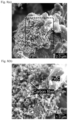
- Figs. 7 are photographs of the state of iron whiskers.
- Fig. 7(a) shows the state of iron whiskers formed in tablet form before a carbon-containing gas was passed therethrough
- Fig. 7(b) shows the state of iron whiskers formed in tablet form after the carbon-containing gas was passed therethrough.
- the configuration of the iron whiskers formed in tablet form before the carbon-containing gas was passed therethrough could not be maintained after the carbon-containing gas was passed therethrough.
- qualitative analysis of the iron whiskers was conducted after the carbon-containing gas had been passed therethrough. Consequently, the surfaces of the iron whiskers were covered with solid-state carbon separated from carbon monoxide after the carbon-containing gas had been passed therethrough.
- Fig. 8(a) is an enlarged photograph of the state of the iron whisker taken with a scanning electron microscope (SEM) after the carbon-containing gas was passed therethrough.
- Fig. 8(b) is an enlarged photograph of a portion surrounded by a broken line indicated in Fig. 8(a) .
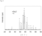
- Fig. 9 shows an XRD profile of the iron whiskers after the carbon-containing gas was passed therethrough. According to Figs.
- the resulting iron whiskers contained solid-state carbon separated from carbon monoxide contained in the carbon-containing gas through a decomposition reaction of the carbon monoxide and thus precipitated on the surfaces of the iron whiskers, and also contained cementite (i.e., iron carbide) formed through the carburization of the iron whiskers with the carbon.
- cementite i.e., iron carbide
- the method for recovering carbon from a carbon-containing gas according to the present invention it is possible to recover carbon separated from carbon monoxide contained in a carbon-containing gas derived from a source gas, such as an exhaust gas, by a decomposition reaction of the carbon monoxide. Further, by using the method for recovering carbon from a carbon-containing gas according to the present invention, it is possible to recover as the separated carbon a carbon solid solution or a metal carbide compound formed by the carburization of the porous material and further by a reaction between the carbon and the porous material.
- the method for recovering carbon from a carbon-containing gas uses a gas obtained by reforming carbon dioxide contained in a source gas, such as an exhaust gas, into carbon monoxide, thereby allowing carbon to be recovered from the carbon dioxide contained in the source gas, such as the exhaust gas.
- a source gas such as an exhaust gas
- the present invention is industrially quite advantageous in, for example, the steel industry in which carbon dioxide is discharged, energy-related industries, such as coal-fired power generation, the chemical industry, the pulp and papermaking industry, and the food processing industry.
Landscapes
- Chemical & Material Sciences (AREA)
- Organic Chemistry (AREA)
- Inorganic Chemistry (AREA)
- Engineering & Computer Science (AREA)
- Materials Engineering (AREA)
- Chemical Kinetics & Catalysis (AREA)
- Carbon And Carbon Compounds (AREA)
- Hydrogen, Water And Hydrids (AREA)
Applications Claiming Priority (2)
| Application Number | Priority Date | Filing Date | Title |
|---|---|---|---|
| JP2022034548 | 2022-03-07 | ||
| PCT/JP2023/007386 WO2023171466A1 (ja) | 2022-03-07 | 2023-02-28 | 炭素含有ガスからの炭素回収方法および炭素回収装置 |
Publications (2)
| Publication Number | Publication Date |
|---|---|
| EP4480907A1 true EP4480907A1 (de) | 2024-12-25 |
| EP4480907A4 EP4480907A4 (de) | 2025-07-09 |
Family
ID=87935229
Family Applications (1)
| Application Number | Title | Priority Date | Filing Date |
|---|---|---|---|
| EP23766644.1A Pending EP4480907A4 (de) | 2022-03-07 | 2023-02-28 | Verfahren und vorrichtung zur rückgewinnung von kohlenstoff aus kohlenstoffhaltigem gas |
Country Status (9)
| Country | Link |
|---|---|
| US (1) | US20250187921A1 (de) |
| EP (1) | EP4480907A4 (de) |
| JP (1) | JP7634692B2 (de) |
| KR (1) | KR20240158291A (de) |
| CN (1) | CN118843601A (de) |
| AU (1) | AU2023231849A1 (de) |
| CA (1) | CA3245472A1 (de) |
| TW (1) | TWI857511B (de) |
| WO (1) | WO2023171466A1 (de) |
Families Citing this family (1)
| Publication number | Priority date | Publication date | Assignee | Title |
|---|---|---|---|---|
| JP2025177714A (ja) * | 2024-05-24 | 2025-12-05 | Jfeスチール株式会社 | 炭材内装鉱の製造方法 |
Family Cites Families (10)
| Publication number | Priority date | Publication date | Assignee | Title |
|---|---|---|---|---|
| JP2002284513A (ja) | 2001-03-28 | 2002-10-03 | Shimadzu Corp | 炭素製造法 |
| EA028873B1 (ru) * | 2009-04-17 | 2018-01-31 | СИРСТОУН ЭлЭлСи | Способ производства твердого углерода путем восстановления оксидов углерода |
| MX354526B (es) * | 2012-04-16 | 2018-03-07 | Seerstone Llc | Metodos y sistemas para capturar y secuestrar carbono y para reducir la masa de oxidos de carbono en una corriente de gas de desechos. |
| JP6379085B2 (ja) | 2012-04-16 | 2018-08-22 | シーアストーン リミテッド ライアビリティ カンパニー | 炭素酸化物を含有するオフガスを処理するための方法 |
| JP2015514669A (ja) | 2012-04-16 | 2015-05-21 | シーアストーン リミテッド ライアビリティ カンパニー | 二酸化炭素を還元することによって固体炭素を生成するための方法 |
| JP5979670B2 (ja) | 2012-11-30 | 2016-08-24 | 一般財団法人電力中央研究所 | 炭素析出の評価方法及び炭素析出の判断方法 |
| CN106457139B (zh) * | 2014-06-04 | 2019-11-05 | 株式会社东芝 | 二氧化碳回收装置及排气的处理方法 |
| US20200016536A1 (en) | 2017-03-31 | 2020-01-16 | Hitachi Chemical Company, Ltd. | Carbon dioxide removal device and method for recovering carbon dioxide adsorption capacity of adsorbent |
| EP3822251A4 (de) | 2018-07-10 | 2021-10-13 | Nippon Steel Corporation | Verfahren zur herstellung von kohlensäureestern und katalytische struktur zur herstellung von kohlensäureestern |
| JP7779543B2 (ja) * | 2020-05-19 | 2025-12-03 | 国立大学法人静岡大学 | 反応システム、固体炭素を捕集する方法、水素を含むガスを製造する方法、触媒セット、及び固体炭素捕集用触媒 |
-
2023
- 2023-02-28 AU AU2023231849A patent/AU2023231849A1/en active Pending
- 2023-02-28 EP EP23766644.1A patent/EP4480907A4/de active Pending
- 2023-02-28 KR KR1020247032426A patent/KR20240158291A/ko active Pending
- 2023-02-28 CA CA3245472A patent/CA3245472A1/en active Pending
- 2023-02-28 CN CN202380024837.7A patent/CN118843601A/zh active Pending
- 2023-02-28 JP JP2023543386A patent/JP7634692B2/ja active Active
- 2023-02-28 US US18/844,171 patent/US20250187921A1/en active Pending
- 2023-02-28 WO PCT/JP2023/007386 patent/WO2023171466A1/ja not_active Ceased
- 2023-03-07 TW TW112108167A patent/TWI857511B/zh active
Also Published As
| Publication number | Publication date |
|---|---|
| US20250187921A1 (en) | 2025-06-12 |
| JP7634692B2 (ja) | 2025-02-21 |
| TWI857511B (zh) | 2024-10-01 |
| CA3245472A1 (en) | 2025-06-13 |
| WO2023171466A1 (ja) | 2023-09-14 |
| AU2023231849A1 (en) | 2024-10-03 |
| KR20240158291A (ko) | 2024-11-04 |
| EP4480907A4 (de) | 2025-07-09 |
| CN118843601A (zh) | 2024-10-25 |
| JPWO2023171466A1 (de) | 2023-09-14 |
| TW202400300A (zh) | 2024-01-01 |
Similar Documents
| Publication | Publication Date | Title |
|---|---|---|
| US20070253886A1 (en) | Carbon sequestration and dry reforming process and catalysts to produce same | |
| US20050220695A1 (en) | Carbon sequestration and dry reforming process and catalysts to produce same | |
| US20170036913A1 (en) | Methods for treating an offgas containing carbon oxides | |
| US20120058030A1 (en) | Catalyst for reforming tar-containing gas, method for preparing catalyst for reforming tar containing gas, method for reforming tar-containing gas using catalyst for reforming tar-containing gas, and method for regenerating catalyst for reforming tar-containing gas | |
| EP2838842A1 (de) | Verfahren und reaktoren zur herstellung von festen kohlenstoffnanoröhrchen, festen kohlenstoffclustern und wäldern | |
| Liu et al. | Performance of potassium-modified Fe2O3/Al2O3 oxygen Carrier in coal-direct chemical looping hydrogen generation | |
| EP2838841A1 (de) | Verfahren zur verwendung von metallkatalysatoren in katalytischen kohlenoxidwandlern | |
| EP2838837A1 (de) | Verfahren und strukturen zur reduzierung von kohlenstoffoxiden mit eisenlosen katalysatoren | |
| EP4464799A1 (de) | Verfahren zur herstellung von heissem metall | |
| EP4480907A1 (de) | Verfahren und vorrichtung zur rückgewinnung von kohlenstoff aus kohlenstoffhaltigem gas | |
| JP5821119B2 (ja) | バイオマスガス化用触媒 | |
| US20240132361A1 (en) | Thermal treatment of coke produced from carbon oxides | |
| Zhang et al. | Chemical looping reforming with water splitting (CLRWS) for syngas and hydrogen coproduction using the ternary metal-oxides (Ca-Fe-Cu–O) as oxygen carriers | |
| Chen et al. | Effect of carbon deposition on the chemical looping hydrogen generation with iron-based oxygen carriers | |
| JP2004261771A (ja) | 無担持炭化水素直接分解触媒およびその製造方法ならびに炭化水素直接分解による水素と炭素の製造方法 | |
| Wang et al. | Reactivity and stability of different pyrites as sulfur carriers for chemical looping decomposition of H2S into H2 and S | |
| Khovavko et al. | Carbon Nanostructured Materials: Synthesis, Characterization, and Industrial Applications | |
| EP4566989A1 (de) | Verfahren zur herstellung von kohlenstoffhaltigem stück | |
| Zong et al. | In-situ formed interface with Fe0 and Gaδ+-Ov in garnets boosting H2 production in chemical looping H2O splitting | |
| JP2025144499A (ja) | セメンタイトの製造方法 | |
| WO2026008712A1 (en) | Process for the valorization of hydrocarbon mixtures and of secondary streams of industrial processes through partial oxidation reaction and co2 separation technologies | |
| Wei et al. | Effect of Gaseous O2 Addition on Carbon Deposition in Chemical-Looping Hydrogen Production |
Legal Events
| Date | Code | Title | Description |
|---|---|---|---|
| STAA | Information on the status of an ep patent application or granted ep patent |
Free format text: STATUS: THE INTERNATIONAL PUBLICATION HAS BEEN MADE |
|
| PUAI | Public reference made under article 153(3) epc to a published international application that has entered the european phase |
Free format text: ORIGINAL CODE: 0009012 |
|
| STAA | Information on the status of an ep patent application or granted ep patent |
Free format text: STATUS: REQUEST FOR EXAMINATION WAS MADE |
|
| 17P | Request for examination filed |
Effective date: 20240918 |
|
| AK | Designated contracting states |
Kind code of ref document: A1 Designated state(s): AL AT BE BG CH CY CZ DE DK EE ES FI FR GB GR HR HU IE IS IT LI LT LU LV MC ME MK MT NL NO PL PT RO RS SE SI SK SM TR |
|
| DAV | Request for validation of the european patent (deleted) | ||
| DAX | Request for extension of the european patent (deleted) | ||
| A4 | Supplementary search report drawn up and despatched |
Effective date: 20250605 |
|
| RIC1 | Information provided on ipc code assigned before grant |
Ipc: B01J 23/745 20060101ALI20250530BHEP Ipc: C01B 32/40 20170101ALI20250530BHEP Ipc: C01B 32/05 20170101AFI20250530BHEP |
|
| STAA | Information on the status of an ep patent application or granted ep patent |
Free format text: STATUS: EXAMINATION IS IN PROGRESS |