EP4401984B1 - Kammerrakeldichtungsanordnung, rakelkammerdichtung und verfahren dafür - Google Patents
Kammerrakeldichtungsanordnung, rakelkammerdichtung und verfahren dafür Download PDFInfo
- Publication number
- EP4401984B1 EP4401984B1 EP23761050.6A EP23761050A EP4401984B1 EP 4401984 B1 EP4401984 B1 EP 4401984B1 EP 23761050 A EP23761050 A EP 23761050A EP 4401984 B1 EP4401984 B1 EP 4401984B1
- Authority
- EP
- European Patent Office
- Prior art keywords
- chamber
- doctor blade
- seal
- doctor
- blade end
- Prior art date
- Legal status (The legal status is an assumption and is not a legal conclusion. Google has not performed a legal analysis and makes no representation as to the accuracy of the status listed.)
- Active
Links
Images


Classifications
-
- B—PERFORMING OPERATIONS; TRANSPORTING
- B41—PRINTING; LINING MACHINES; TYPEWRITERS; STAMPS
- B41F—PRINTING MACHINES OR PRESSES
- B41F5/00—Rotary letterpress machines
- B41F5/24—Rotary letterpress machines for flexographic printing
-
- B—PERFORMING OPERATIONS; TRANSPORTING
- B41—PRINTING; LINING MACHINES; TYPEWRITERS; STAMPS
- B41F—PRINTING MACHINES OR PRESSES
- B41F9/00—Rotary intaglio printing presses
- B41F9/06—Details
- B41F9/08—Wiping mechanisms
- B41F9/10—Doctors, scrapers, or like devices
- B41F9/1063—Seals between blades and cylinder
-
- B—PERFORMING OPERATIONS; TRANSPORTING
- B41—PRINTING; LINING MACHINES; TYPEWRITERS; STAMPS
- B41F—PRINTING MACHINES OR PRESSES
- B41F9/00—Rotary intaglio printing presses
- B41F9/06—Details
- B41F9/08—Wiping mechanisms
- B41F9/10—Doctors, scrapers, or like devices
- B41F9/1081—Doctors, scrapers, or like devices using two or more blades
-
- B—PERFORMING OPERATIONS; TRANSPORTING
- B41—PRINTING; LINING MACHINES; TYPEWRITERS; STAMPS
- B41F—PRINTING MACHINES OR PRESSES
- B41F31/00—Inking arrangements or devices
- B41F31/02—Ducts, containers, supply or metering devices
- B41F31/027—Ink rail devices for inking ink rollers
-
- B—PERFORMING OPERATIONS; TRANSPORTING
- B41—PRINTING; LINING MACHINES; TYPEWRITERS; STAMPS
- B41F—PRINTING MACHINES OR PRESSES
- B41F31/00—Inking arrangements or devices
- B41F31/02—Ducts, containers, supply or metering devices
- B41F31/06—Troughs or like reservoirs with immersed or partly immersed, rollers or cylinders
-
- B—PERFORMING OPERATIONS; TRANSPORTING
- B41—PRINTING; LINING MACHINES; TYPEWRITERS; STAMPS
- B41F—PRINTING MACHINES OR PRESSES
- B41F9/00—Rotary intaglio printing presses
- B41F9/06—Details
- B41F9/061—Inking devices
Definitions
- the invention relates to a chamber doctor blade seal arrangement for a chamber doctor blade system for supplying printing ink to a printing system with anilox roller, in particular for flexographic printing and coating processes, with a doctor blade chamber which extends longitudinally over the printing width and which, with a chamber base and two opposite side webs, forms a cavity filled with the printing ink and has doctor blades on the side webs, and with doctor blade chamber seals which seal the cavity to the anilox roller above it on both end faces of the doctor blade chamber which extends longitudinally over the printing width, the doctor blade chamber seal being formed from an elastic sealing body whose shape corresponds to the free cross section on the end face of the doctor blade chamber.
- the invention further relates to a doctor blade chamber seal for this chamber doctor blade seal arrangement and a method for inserting this doctor blade chamber seal.
- Chambered doctor blade systems are known for dosing the amount of ink for printing systems, particularly for flexographic printing but also for coatings.
- the ink is fed into the printing system via a doctor blade chamber, whereby the doctor blade chamber extends over the entire working width of the printing unit and rests against an anilox roller, which thus takes ink from the doctor blade chamber when it rotates, whereby excess ink is scraped off the anilox roller via the doctor blade.
- Doctor blade chamber seals are used on the short end faces of the elongated doctor blade chambers, which seal the cavity to the open end face and the anilox roller above it.
- the chamber doctor blade seal arrangement mentioned above and the doctor blade chamber seal for it are from the US 9 085 131 B1 known, whereby the doctor blade chamber seal described therein is intended to provide pressure relief in the area where the seal, anilox roller and doctor blade meet. This is intended to give the doctor blade chamber seals a longer service life. However, the doctor blades still have to be removed to change the doctor blade chamber seals.
- US 2009/000499 A1 a chamber doctor blade seal arrangement in which drainage channels are provided in the doctor blade chamber end seals for draining printing ink which passes through the inner seals of the doctor blade chamber end seals and is collected in the doctor blade chamber.
- the self-lubricating doctor chamber seals according to US 8 925 455 B2 to hold a lubricant in a receiving volume between two flanks of a seal in order to improve the service life and reliability of the seal on the anilox roller.
- the WO 2013/104366 A1 a printing unit with a doctor chamber and an anilox roller rotating therein or a doctor chamber seal suitable for this purpose is known.
- the doctor chamber seal has a sealing surface that faces the chamber floor of the doctor chamber, with the sealing body extending over the front surface of the doctor chamber.
- the seal according to the WO 2013/104366 A1 has a two-legged cross-section and has a first leg, which forms an inclined surface to the interior (cavity) of the doctor chamber that is exposed to ink. The preferred angle between this inclined surface and the lower sealing surface to the chamber floor should be 40° to 60°.
- the seal also has a stiffer support rail at its upper end, which forms the seal with an elastomer edge via a concave shape to the anilox roller.
- the DE 196 31 301 A1 describes an ink chamber doctor blade for a printing machine, with particular attention being paid to sealing the front ends of the ink chamber doctor blade against unwanted ink leakage.
- a two-part design made of an inner, flexible material and an outer, solid material is specified, with the assembly again comprising fastening and clamping screws.
- the DE 20 2009 013 643 U1 describes a two-part sealing element for sealing the front of doctor blade chambers, particularly on flexographic printing machines, which also provides for a design with two different materials, namely a soft material that lies against the ink roller and a firmer material underneath (i.e. radially away from the roller).
- the softer piece of material with the concavely shaped inner part is equipped with a web that fixes this softer piece of material in the firmer material so that it cannot slip.
- a groove is provided in the firmer material into which the web of the softer piece of material engages. No statements are made about the fastening of this two-part sealing element, particularly the firmer piece of material to the front of the doctor blade chamber.
- the tongue and groove connection ensures that the seal is securely fixed in place when the elastic doctor blade chamber seal is inserted into the doctor blade chamber. Because only one groove needs to be provided in the chamber floor of a doctor blade chamber, the ability of the doctor blade chamber to be cleaned is hardly impaired.
- the groove at the front end is arranged parallel to the plane of the doctor blade chamber spanned by the front side and is therefore not directly exposed to ink.
- the linear support of the doctor blade chamber seal via the spring provided on it via the groove arranged essentially perpendicular to the longitudinal extension of the doctor blade chamber not only prevents displacement but also unwanted rotation of the doctor blade chamber seal.
- No tools are required for the assembly or disassembly of the doctor chamber seal in/out of the doctor chamber. Assembly can be done manually, as the doctor chamber seal is inserted into the cavity between the two opposing doctor blades, rotated by 90° and then moved outwards towards the front side and pivoted into its intended position, whereby the spring of the The doctor blade chamber seal engages in the groove in the chamber floor. When dismantling, proceed in exactly the reverse order.
- the spring on the doctor chamber seal is made up of two or more spring sections, the support of the doctor chamber seal in the groove in the chamber floor of the doctor chamber can be distributed over two or more separate spring sections. This ensures that the doctor chamber seal remains correctly positioned and cannot twist.
- the groove in the chamber floor can preferably be formed from two or more groove sections.
- the separately arranged spring sections then engage in correspondingly assigned groove sections in the chamber floor of the doctor chamber.
- the doctor chamber seal is formed in two parts from the elastic sealing body and a seal holder part made of a stiffer material, wherein the seal holder part has the spring and/or spring sections and connecting means for coupling to the sealing body, the supporting effect of the doctor chamber seal engaging in the groove can be increased to the extent that the material used for the seal holder part is stiffer than the more elastic material for the sealing body.
- the connecting means on the flat seal holder part are orthogonally protruding pins which can be inserted into precisely fitting holes in the seal body.
- the doctor chamber seal has a cup shape with a closed cup bottom, a cup opening spanned by a cup wall and a sealing edge surrounding the cup opening, whereby when the doctor chamber seal is inserted into the doctor chamber as intended, the cup opening leads to the ink-filled cavity, the formability and adaptability of the doctor chamber seal and in particular of its circumferential sealing edge is increased, so that undesirable ink leaking out of the front surface of the doctor chamber is largely avoided.
- inserting and removing the doctor chamber seal into the doctor chamber is easier when it is designed in the shape of a cup.
- ink from the doctor chamber entering the cup opening under slight overpressure increases the sealing effect, since the slight overpressure presses the cup migration and in particular the sealing edge against the doctor chamber or against the anilox roller, thus supporting the snuggling of the circumferential sealing edge against the chamber floor, the side webs, the doctor blades and the anilox roller.
- the cup wall has a wall thickness that decreases from the cup base to the sealing edge. This further improves the conformability of the doctor chamber seal to the doctor chamber or to the anilox roller, thus ensuring a very reliable seal.
- the doctor chamber seal becomes more dimensionally stable thanks to the stiffening part, while at the same time the high sealing effect described above is maintained on the surrounding sealing edge. It is also particularly easy to manually grasp the doctor chamber seal at the stiffening part and insert it into the doctor chamber.
- doctor blade chamber seal for this arrangement is also the subject of the utility model.
- the doctor blade chamber seal is preferably made of an elastic and dimensionally stable rubber or plastic. Stiffer materials provide a high level of tightness while at the same time being sufficiently stable to be able to extend the replacement intervals.
- the contact area of the doctor blade chamber seal with the rapidly rotating anilox roller during printing is coated with Teflon.
- the working method for inserting this doctor chamber seal is characterized by the following steps: feeding the doctor chamber seal to the elongated doctor chamber in the desired installation orientation, but rotated by 90° about an axis orthogonal to the chamber floor, into the cavity between the two opposing doctor blades; rotating the doctor chamber seal back about the orthogonal axis by 90° and in the process tilting the doctor chamber seal by 20° to 60° from the plane of the front side inwards towards the cavity in the direction of the chamber floor; moving the doctor chamber seal oriented in this way to align its protruding spring with the groove arranged on the relevant front side in the chamber floor; and tilting the doctor chamber seal back by 20° to 60° from the plane of the front side outwards in relation to the cavity in an orientation perpendicular to the chamber floor, parallel to the plane of the front side, whereby the protruding spring slides into the groove arranged in the chamber floor and the doctor chamber seal is anchored in the doctor chamber to seal the cavity.
- doctor chamber seal is very easy to insert and, of course, remove (in the reverse order of the process steps) from the doctor chamber without the use of tools or even dismantling the doctor blades.
- the elastic doctor chamber seal slides almost automatically into the groove provided in the chamber floor with its spring when tilted back into the installation position and ensures precise and sealed positioning of the doctor chamber seal.
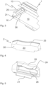
- FIG. 1 A chamber doctor seal arrangement with an inserted doctor chamber seal 2 is shown in three-dimensional view.
- the doctor chamber 1 is designed here as an elongated extruded profile and has a chamber base 10, a first and second side web 11, 12, doctor blades 13 inserted on the side webs 11 and 12 and a front side 15 at each end.
- Fig. 1 only one end of the doctor chamber 1 is shown.
- the other end face 15 is also closed with a doctor chamber seal 2.
- Fig. 1 A chamber doctor seal arrangement with an inserted doctor chamber seal 2 is shown in three-dimensional view.
- the doctor chamber 1 is designed here as an elongated extruded profile and has a chamber base 10, a first and second side web 11, 12, doctor blades 13 inserted on the side webs 11 and 12 and a front side 15 at each end.
- Fig. 1 only one end of the doctor chamber 1 is shown.
- the other end face 15 is also closed with a doctor chamber seal 2.
- an anilox roller belonging to the printing system runs above the doctor chamber 1 and closes off a cavity 14 formed by the chamber floor 10, the two side webs 11, 12 with the doctor blades 13 and the doctor chamber seals 2 inserted in the front sides 15, whereby the anilox roller is guided in contact along the doctor blades 13 and the concave shape of the doctor chamber seals 2.
- the anilox roller is not shown here for the sake of clarity.
- FIG. 2 The longitudinal section shown shows the anchoring of the doctor chamber seal 2 in the doctor chamber 1.
- a groove 16 is formed in the chamber floor 10 of the doctor chamber 1, into which a spring 21 formed on the doctor chamber seal 2 engages.
- the sealing body 20 consists of elastic material, onto which the spring 21 is formed.
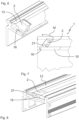
- Fig. 3 shown in a spatial, partly sectioned view, with details to be provided later.
- Fig. 4 and 5 is the doctor chamber seal 2 according to the first embodiment, which is also in the Figures 1 to 3 is used, shown in detail.
- Fig. 4 shows a spatial view of the doctor chamber seal 2 when properly inserted into the Doctor chamber 1 facing outwards.
- the doctor chamber seal 2 is shown from the inside.
- the doctor chamber seal 2 has a cup shape, with the closed cup bottom 23 in Fig. 4 is visible.
- the cup-shaped doctor chamber seal 2 can be seen from the cup opening 24.
- the cup wall running around the cup opening 24 forms the sealing edge 25 at the opening, which, when the doctor chamber seal 2 is inserted into the doctor chamber 1 as intended, is oriented in Fig.
- a stiffening part 26 protruding into the interior (cup opening 24) is formed from the cup bottom 23 within the cup opening 24, as can also be seen in the sectional view of the Fig. 2 and Fig. 3 is evident.
- Fig. 6 the process of inserting the doctor chamber seal 2 into the doctor chamber 1 is shown. Due to the cup shape, the sealing edge 25 can also be pushed slightly inwards when inserting the doctor chamber seal 2, if necessary, so that the doctor chamber seal 2 can be inserted first 90 ° for the intended positioning in the doctor chamber 1 between the doctor blades 13 and then rotated into the desired orientation essentially parallel to the front side 15, but still inclined, as in Fig. 6 and especially in the longitudinal section Fig. 7 , then lock it in place by sliding and unfolding the doctor chamber seal 2 in the direction of arrow M and thus inserting the spring 21 into the groove 16 in the chamber base 10. No tools are required for this work. No tools are required to remove the doctor chamber seal 2 from the doctor chamber 1 either. Disassembly is carried out in the reverse order to that already described for assembly.
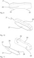
- Fig. 8 shown in a three-dimensional view. It can be clearly seen that the doctor chamber seal 2 between the two doctor blades 13 protruding from the side webs 11, 12 is grasped by the fitter and can be inserted into the groove 16 arranged parallel to the front side 15 with its molded spring 21 or can be removed in the reverse order. It is also not necessary to remove the doctor blades 13 for this purpose.
- the doctor chamber seal 2' has a two-part spring 21 in the form of two spring sections 22, which, as in Fig. 6 or 8 shown, can be inserted into the groove 16 of the doctor chamber 1.
- the groove 16 in the doctor chamber 1 can also be formed from two groove sections corresponding to the spring sections 22 of the associated doctor chamber seal 2'.
- the two spring sections 22 could also be very short in the form of protruding pins which engage in corresponding holes as very short groove sections in the chamber floor 10.
- the doctor chamber seal 2" is formed from a sealing body 20 made of elastic rubber or plastic, wherein a separate seal holder part 27 made of a stiffer material is provided, which can be connected via connecting means, here two pins 28 projecting orthogonally from the flat seal holder part 27, which can be inserted into associated, matching bores 29 in the sealing body 20 (see Fig. 10 and 11 ).
- the spring 21 is formed on the seal holder part 27 and can engage in the groove 16 in the doctor chamber 1.
- Fig. 12 shown in a longitudinal section.
- the doctor chamber seal 2" is inserted or removed without tools, since the doctor chamber seal 2" is also inserted into the doctor chamber 1 between the
- the sealing body 20 can be inserted so as to reach through the doctor blades 13, rotated by 90° and then pre-positioned at an angle to the position on the front side 15 close to the groove 16 and then pivoted into the correct position according to the assembly arrow M. Due to the elasticity of the sealing body 20, an approximately cuboid-shaped component can also be moved into the correct position below the doctor blades 13, positioned and secured by pivoting the spring 21 arranged on the sealing holder part 27 into the groove 16 in the doctor chamber 1. Due to the stiffer sealing holder part 27, which secures the elastic sealing body 20 over its surface by inserting it into the groove 16, a high sealing effect can also be achieved in this design with easy assembly/dismantling.
Landscapes
- Engineering & Computer Science (AREA)
- Mechanical Engineering (AREA)
- Inking, Control Or Cleaning Of Printing Machines (AREA)
Applications Claiming Priority (2)
| Application Number | Priority Date | Filing Date | Title |
|---|---|---|---|
| DE202022104909.2U DE202022104909U1 (de) | 2022-08-31 | 2022-08-31 | Kammerrakeldichtungsanordnung und Rakelkammerdichtung dafür |
| PCT/DE2023/100582 WO2024046526A1 (de) | 2022-08-31 | 2023-08-08 | Kammerrakeldichtungsanordnung, rakelkammerdichtung und verfahren dafür |
Publications (3)
| Publication Number | Publication Date |
|---|---|
| EP4401984A1 EP4401984A1 (de) | 2024-07-24 |
| EP4401984C0 EP4401984C0 (de) | 2024-10-23 |
| EP4401984B1 true EP4401984B1 (de) | 2024-10-23 |
Family
ID=87801117
Family Applications (1)
| Application Number | Title | Priority Date | Filing Date |
|---|---|---|---|
| EP23761050.6A Active EP4401984B1 (de) | 2022-08-31 | 2023-08-08 | Kammerrakeldichtungsanordnung, rakelkammerdichtung und verfahren dafür |
Country Status (5)
| Country | Link |
|---|---|
| EP (1) | EP4401984B1 (pl) |
| DE (1) | DE202022104909U1 (pl) |
| ES (1) | ES2995875T3 (pl) |
| PL (1) | PL4401984T3 (pl) |
| WO (1) | WO2024046526A1 (pl) |
Family Cites Families (7)
| Publication number | Priority date | Publication date | Assignee | Title |
|---|---|---|---|---|
| DE4414681A1 (de) * | 1993-05-27 | 1994-12-01 | Roland Man Druckmasch | Kammerrakel |
| DE19631301A1 (de) * | 1996-08-02 | 1998-02-05 | Gorter Cornelis | Farbkammerrakel für eine Druckmaschine |
| SE527080C2 (sv) * | 2004-05-05 | 2005-12-20 | Akeboose Internat Ab | Anordning och förfarande för kammarrakel |
| DE202009013643U1 (de) * | 2009-10-26 | 2011-03-17 | Zeljko, Kitic | Dichtelement |
| EP2425972B1 (en) * | 2010-09-01 | 2016-01-13 | Anthony Foley | Self-lubricating seal for enclosed doctor blade assembly |
| DK201270014A (da) | 2012-01-10 | 2013-07-11 | Tresu As | Pakning til kammerrakel |
| US9085131B1 (en) * | 2012-06-08 | 2015-07-21 | Valley Holdings, Llc | End seal for an ink chamber of a printing machine |
-
2022
- 2022-08-31 DE DE202022104909.2U patent/DE202022104909U1/de active Active
-
2023
- 2023-08-08 ES ES23761050T patent/ES2995875T3/es active Active
- 2023-08-08 WO PCT/DE2023/100582 patent/WO2024046526A1/de not_active Ceased
- 2023-08-08 PL PL23761050.6T patent/PL4401984T3/pl unknown
- 2023-08-08 EP EP23761050.6A patent/EP4401984B1/de active Active
Also Published As
| Publication number | Publication date |
|---|---|
| EP4401984C0 (de) | 2024-10-23 |
| WO2024046526A1 (de) | 2024-03-07 |
| ES2995875T3 (en) | 2025-02-11 |
| EP4401984A1 (de) | 2024-07-24 |
| PL4401984T3 (pl) | 2025-02-24 |
| DE202022104909U1 (de) | 2023-12-01 |
Similar Documents
| Publication | Publication Date | Title |
|---|---|---|
| EP0374092B1 (de) | Farbwerk für Druckmaschine | |
| DE69702952T2 (de) | Farbwerk für Druckmaschine und Verfahren | |
| DE68922302T2 (de) | Vorrichtung zum Einfärben eines Druckzylinders. | |
| EP1485209A1 (de) | Rakel-dosiersystem | |
| EP3539776A1 (de) | Dichtungselement | |
| DE10045515B4 (de) | Rakel-Dosiersystem | |
| EP4401984B1 (de) | Kammerrakeldichtungsanordnung, rakelkammerdichtung und verfahren dafür | |
| DE3119605A1 (de) | Raeumvorrichtung | |
| WO2004096545A2 (de) | Farbtransport am siebdruckzylinder | |
| DE3884939T3 (de) | Spannungsloser Plattenverschluss. | |
| EP2821228B1 (de) | Dichtung für Rakeleinrichtungen | |
| EP4476072A1 (de) | Endabdichtung | |
| EP0113669A2 (de) | Zylinder für Tiefdruckmaschinen | |
| DE19625375A1 (de) | Befestigungselement vom Klammertyp | |
| DE2121211C3 (de) | Vorrichtung zum Abdichten der Berührungsstellen zweier, relativ gegeneinander bewegbarer Maschinenelemente | |
| DE102016104334B4 (de) | Mischwerkzeugherstellungsverfahren | |
| EP0849080B1 (de) | Kanalabdeckung bei einem Druckzylinder einer Offsetdruckmaschine | |
| DE102007009881B4 (de) | Rakelfarbkasten | |
| EP4585315A1 (de) | Endabdichtung | |
| DE10302288B4 (de) | Dichtschild | |
| WO2008083766A1 (de) | Abgedichtete kette mit spritzgegossenen dichtungen | |
| DE10127133A1 (de) | Zylinder mit einer Klemmeinrichtung in einer Druckmaschine | |
| DE102005040929B4 (de) | Farbkammerrakel | |
| DE3421392A1 (de) | Dichtungsanordnung fuer eine walzen-dosiereinrichtung fuer fluessigkeiten | |
| DE10244945A1 (de) | Vorrichtung zum Befestigen einer flexiblen Bespannung auf Druckzylinder |
Legal Events
| Date | Code | Title | Description |
|---|---|---|---|
| STAA | Information on the status of an ep patent application or granted ep patent |
Free format text: STATUS: UNKNOWN |
|
| STAA | Information on the status of an ep patent application or granted ep patent |
Free format text: STATUS: THE INTERNATIONAL PUBLICATION HAS BEEN MADE |
|
| GRAP | Despatch of communication of intention to grant a patent |
Free format text: ORIGINAL CODE: EPIDOSNIGR1 |
|
| STAA | Information on the status of an ep patent application or granted ep patent |
Free format text: STATUS: GRANT OF PATENT IS INTENDED |
|
| PUAI | Public reference made under article 153(3) epc to a published international application that has entered the european phase |
Free format text: ORIGINAL CODE: 0009012 |
|
| 17P | Request for examination filed |
Effective date: 20240418 |
|
| AK | Designated contracting states |
Kind code of ref document: A1 Designated state(s): AL AT BE BG CH CY CZ DE DK EE ES FI FR GB GR HR HU IE IS IT LI LT LU LV MC ME MK MT NL NO PL PT RO RS SE SI SK SM TR |
|
| GRAS | Grant fee paid |
Free format text: ORIGINAL CODE: EPIDOSNIGR3 |
|
| GRAA | (expected) grant |
Free format text: ORIGINAL CODE: 0009210 |
|
| STAA | Information on the status of an ep patent application or granted ep patent |
Free format text: STATUS: THE PATENT HAS BEEN GRANTED |
|
| AK | Designated contracting states |
Kind code of ref document: B1 Designated state(s): AL AT BE BG CH CY CZ DE DK EE ES FI FR GB GR HR HU IE IS IT LI LT LU LV MC ME MK MT NL NO PL PT RO RS SE SI SK SM TR |
|
| DAV | Request for validation of the european patent (deleted) | ||
| DAX | Request for extension of the european patent (deleted) | ||
| REG | Reference to a national code |
Ref country code: GB Ref legal event code: FG4D Free format text: NOT ENGLISH |
|
| REG | Reference to a national code |
Ref country code: CH Ref legal event code: EP |
|
| REG | Reference to a national code |
Ref country code: DE Ref legal event code: R096 Ref document number: 502023000233 Country of ref document: DE |
|
| REG | Reference to a national code |
Ref country code: IE Ref legal event code: FG4D Free format text: LANGUAGE OF EP DOCUMENT: GERMAN |
|
| U01 | Request for unitary effect filed |
Effective date: 20241023 |
|
| U07 | Unitary effect registered |
Designated state(s): AT BE BG DE DK EE FI FR IT LT LU LV MT NL PT RO SE SI Effective date: 20241029 |
|
| REG | Reference to a national code |
Ref country code: ES Ref legal event code: FG2A Ref document number: 2995875 Country of ref document: ES Kind code of ref document: T3 Effective date: 20250211 |
|
| PG25 | Lapsed in a contracting state [announced via postgrant information from national office to epo] |
Ref country code: HR Free format text: LAPSE BECAUSE OF FAILURE TO SUBMIT A TRANSLATION OF THE DESCRIPTION OR TO PAY THE FEE WITHIN THE PRESCRIBED TIME-LIMIT Effective date: 20241023 Ref country code: IS Free format text: LAPSE BECAUSE OF FAILURE TO SUBMIT A TRANSLATION OF THE DESCRIPTION OR TO PAY THE FEE WITHIN THE PRESCRIBED TIME-LIMIT Effective date: 20250223 |
|
| PG25 | Lapsed in a contracting state [announced via postgrant information from national office to epo] |
Ref country code: NO Free format text: LAPSE BECAUSE OF FAILURE TO SUBMIT A TRANSLATION OF THE DESCRIPTION OR TO PAY THE FEE WITHIN THE PRESCRIBED TIME-LIMIT Effective date: 20250123 |
|
| PG25 | Lapsed in a contracting state [announced via postgrant information from national office to epo] |
Ref country code: GR Free format text: LAPSE BECAUSE OF FAILURE TO SUBMIT A TRANSLATION OF THE DESCRIPTION OR TO PAY THE FEE WITHIN THE PRESCRIBED TIME-LIMIT Effective date: 20250124 |
|
| PG25 | Lapsed in a contracting state [announced via postgrant information from national office to epo] |
Ref country code: RS Free format text: LAPSE BECAUSE OF FAILURE TO SUBMIT A TRANSLATION OF THE DESCRIPTION OR TO PAY THE FEE WITHIN THE PRESCRIBED TIME-LIMIT Effective date: 20250123 |
|
| PG25 | Lapsed in a contracting state [announced via postgrant information from national office to epo] |
Ref country code: SM Free format text: LAPSE BECAUSE OF FAILURE TO SUBMIT A TRANSLATION OF THE DESCRIPTION OR TO PAY THE FEE WITHIN THE PRESCRIBED TIME-LIMIT Effective date: 20241023 |
|
| PG25 | Lapsed in a contracting state [announced via postgrant information from national office to epo] |
Ref country code: SK Free format text: LAPSE BECAUSE OF FAILURE TO SUBMIT A TRANSLATION OF THE DESCRIPTION OR TO PAY THE FEE WITHIN THE PRESCRIBED TIME-LIMIT Effective date: 20241023 |
|
| PG25 | Lapsed in a contracting state [announced via postgrant information from national office to epo] |
Ref country code: CZ Free format text: LAPSE BECAUSE OF FAILURE TO SUBMIT A TRANSLATION OF THE DESCRIPTION OR TO PAY THE FEE WITHIN THE PRESCRIBED TIME-LIMIT Effective date: 20241023 |
|
| PLBE | No opposition filed within time limit |
Free format text: ORIGINAL CODE: 0009261 |
|
| STAA | Information on the status of an ep patent application or granted ep patent |
Free format text: STATUS: NO OPPOSITION FILED WITHIN TIME LIMIT |
|
| 26N | No opposition filed |
Effective date: 20250724 |
|
| U20 | Renewal fee for the european patent with unitary effect paid |
Year of fee payment: 3 Effective date: 20250826 |
|
| PGFP | Annual fee paid to national office [announced via postgrant information from national office to epo] |
Ref country code: ES Payment date: 20250917 Year of fee payment: 3 |
|
| PGFP | Annual fee paid to national office [announced via postgrant information from national office to epo] |
Ref country code: PL Payment date: 20250725 Year of fee payment: 3 |